EP2131011A2 - Particle resistant in-wall cooling passage inlet - Google Patents
Particle resistant in-wall cooling passage inlet Download PDFInfo
- Publication number
- EP2131011A2 EP2131011A2 EP09250803A EP09250803A EP2131011A2 EP 2131011 A2 EP2131011 A2 EP 2131011A2 EP 09250803 A EP09250803 A EP 09250803A EP 09250803 A EP09250803 A EP 09250803A EP 2131011 A2 EP2131011 A2 EP 2131011A2
- Authority
- EP
- European Patent Office
- Prior art keywords
- cooling passage
- wall
- turbine engine
- engine component
- cooling
- Prior art date
- Legal status (The legal status is an assumption and is not a legal conclusion. Google has not performed a legal analysis and makes no representation as to the accuracy of the status listed.)
- Granted
Links
Images
Classifications
-
- F—MECHANICAL ENGINEERING; LIGHTING; HEATING; WEAPONS; BLASTING
- F01—MACHINES OR ENGINES IN GENERAL; ENGINE PLANTS IN GENERAL; STEAM ENGINES
- F01D—NON-POSITIVE DISPLACEMENT MACHINES OR ENGINES, e.g. STEAM TURBINES
- F01D5/00—Blades; Blade-carrying members; Heating, heat-insulating, cooling or antivibration means on the blades or the members
- F01D5/12—Blades
- F01D5/14—Form or construction
- F01D5/18—Hollow blades, i.e. blades with cooling or heating channels or cavities; Heating, heat-insulating or cooling means on blades
- F01D5/187—Convection cooling
-
- F—MECHANICAL ENGINEERING; LIGHTING; HEATING; WEAPONS; BLASTING
- F01—MACHINES OR ENGINES IN GENERAL; ENGINE PLANTS IN GENERAL; STEAM ENGINES
- F01D—NON-POSITIVE DISPLACEMENT MACHINES OR ENGINES, e.g. STEAM TURBINES
- F01D25/00—Component parts, details, or accessories, not provided for in, or of interest apart from, other groups
- F01D25/32—Collecting of condensation water; Drainage ; Removing solid particles
-
- F—MECHANICAL ENGINEERING; LIGHTING; HEATING; WEAPONS; BLASTING
- F05—INDEXING SCHEMES RELATING TO ENGINES OR PUMPS IN VARIOUS SUBCLASSES OF CLASSES F01-F04
- F05D—INDEXING SCHEME FOR ASPECTS RELATING TO NON-POSITIVE-DISPLACEMENT MACHINES OR ENGINES, GAS-TURBINES OR JET-PROPULSION PLANTS
- F05D2260/00—Function
- F05D2260/20—Heat transfer, e.g. cooling
- F05D2260/204—Heat transfer, e.g. cooling by the use of microcircuits
Definitions
- the present disclosure relates to a cooling passage inlet for an in-wall cooling passage for a turbine airfoil which discourages particles from entering the cooling passage.
- High performance turbine airfoil cooling schemes require small cooling passages in the airfoil walls. These passages can be susceptible to blockage from particles of foreign materials present in the cooling air supply to the airfoil. Blockage of a cooling passage can result in reduced local cooling.
- in-wall cooling passages using a variety of means, including refractory metal core casting.
- the inlet holes for these passages may be formed with small tabs extending from a main portion of an RMC core into the ceramic core of the airfoil. These holes have been axially oriented and have no special features to prevent particles from entering the cooling passage.
- a small in-wall cooling passage for a turbine engine component which broadly comprises a first cooling passage and said first cooling passage has at least one inlet means for preventing particles from entering said cooling passage and for dislodging particles which become lodged in the inlet means.
- a turbine engine component which broadly comprises an airfoil portion having a tip, at least one cooling passage within the wall of the airfoil portion, and each airfoil wall cooling passage having at least one inlet means for preventing particles from entering the cooling passage and for dislodging particles which may become lodged in the at least one inlet means.
- the present disclosure relates to a change in the geometry of cooling passages inlets to prevent particles from entering the cooling passages and at least partially blocking flow of the cooling fluid within the cooling passages.
- the inlets are skewed in a radially outward direction.
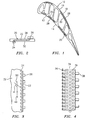
- FIG. 1 is a sectional view of an airfoil portion 10 of a turbine engine component such as a blade or vane.
- the airfoil portion has a wall 12 which form a pressure side surface 14 and a wall 16 which form a suction side surface 18.
- Each of the walls 12 and 16 has an outer wall 28 and the inner wall 30.
- Embedded within each of the walls 12 and 16 is one or more cooling passages 22 for example microcircuits.
- each cooling passage 22 has one or more cooling passage inlets 24 for allowing a cooling fluid to enter the cooling passage 22 and one or more cooling passage exits 26 for allowing cooling fluid to exit the cooling passage 22 and flow over the airfoil skin outer wall 28.
- the cooling passages 22 may be used solely to perform in-wall cooling without having fluid flow over the outer wall.
- the cooling passage 22 is located between the airfoil skin outer wall 28 and the airfoil skin inner wall 30.
- each inlet 24 is radially skewed in an outward direction.
- the term "outward direction” refers to the direction towards the tip of the airfoil portion.
- a particle 48 flowing in the cooling supply passageway 32 tends to bypass the inlets 24.
- Each inlet 24 may be at an angle ⁇ of at least 100 degrees with respect to the flow direction 50 of the cooling fluid in the cooling supply passageway 32. In a particularly useful embodiment, the angle ⁇ may be in the range of from 120 degrees to 160 degrees with respect to the flow direction 50.
- the passage 22 with the radially skewed inlets 24 may be formed using a refractory metal core 34 (see FIG. 4 ) having appropriately angled tabs 36 for forming the inlets 24 and tabs 38 for forming the outlets 26.
- the refractory metal core 34 may have a plurality of holes 39 which may be used to form a plurality of flow metering features (not shown) in the passage 22.
- cooling passage inlets discourages particles from entering cooling passages, particularly small cooling passages in the airfoil walls. This is because the particles would have to make a significant change in direction and fight the centrifugal force from a rotating blade in order to enter the passage inlets. Part durability should be increased due to a reduced potential for plugging the cooling passage.
- smaller flow metering features can be used, allowing for reduced component cooling flow and increased engine performance.
- the radially skewed inlets also will tend to throw out any particle which does become lodged.
Landscapes
- Engineering & Computer Science (AREA)
- Mechanical Engineering (AREA)
- General Engineering & Computer Science (AREA)
- Turbine Rotor Nozzle Sealing (AREA)
Abstract
Description
- The present disclosure relates to a cooling passage inlet for an in-wall cooling passage for a turbine airfoil which discourages particles from entering the cooling passage.
- High performance turbine airfoil cooling schemes require small cooling passages in the airfoil walls. These passages can be susceptible to blockage from particles of foreign materials present in the cooling air supply to the airfoil. Blockage of a cooling passage can result in reduced local cooling.
- It is known to manufacture in-wall cooling passages using a variety of means, including refractory metal core casting. The inlet holes for these passages may be formed with small tabs extending from a main portion of an RMC core into the ceramic core of the airfoil. These holes have been axially oriented and have no special features to prevent particles from entering the cooling passage.
- In accordance with the instant disclosure, there is described a small in-wall cooling passage for a turbine engine component which broadly comprises a first cooling passage and said first cooling passage has at least one inlet means for preventing particles from entering said cooling passage and for dislodging particles which become lodged in the inlet means.
- Further in accordance with the instant disclosure there is described a turbine engine component which broadly comprises an airfoil portion having a tip, at least one cooling passage within the wall of the airfoil portion, and each airfoil wall cooling passage having at least one inlet means for preventing particles from entering the cooling passage and for dislodging particles which may become lodged in the at least one inlet means.
- Other details of the particle resistant in-wall cooling passage inlet are set forth in the following detailed description and the accompanying drawings wherein like reference numerals depict like elements.
-
-
FIG. 1 is a sectional view of an airfoil portion of a turbine engine component. -
FIG. 2 is a sectional view of a cooling passage within said airfoil portion. -
FIG. 3 is a schematic representation of the cooling passage inlet relative to a flow of cooling fluid within a cooling supply passageway. -
FIG. 4 is a schematic representation of a refractory metal core for forming an in-wall cooling passage having angled inlets. - The present disclosure relates to a change in the geometry of cooling passages inlets to prevent particles from entering the cooling passages and at least partially blocking flow of the cooling fluid within the cooling passages. In accordance with the present disclosure, the inlets are skewed in a radially outward direction.
-
FIG. 1 is a sectional view of anairfoil portion 10 of a turbine engine component such as a blade or vane. The airfoil portion has awall 12 which form apressure side surface 14 and awall 16 which form asuction side surface 18. Each of thewalls outer wall 28 and theinner wall 30. Embedded within each of thewalls more cooling passages 22 for example microcircuits. - As shown in
FIG. 2 , eachcooling passage 22 has one or morecooling passage inlets 24 for allowing a cooling fluid to enter thecooling passage 22 and one or morecooling passage exits 26 for allowing cooling fluid to exit thecooling passage 22 and flow over the airfoil skinouter wall 28. If desired, thecooling passages 22 may be used solely to perform in-wall cooling without having fluid flow over the outer wall. As can be seen fromFIG. 2 , thecooling passage 22 is located between the airfoil skinouter wall 28 and the airfoil skininner wall 30. - Referring now to
FIG. 3 , there is shown acooling passage 22 having a plurality ofinlets 24. Eachinlet 24 is radially skewed in an outward direction. As used herein, the term "outward direction" refers to the direction towards the tip of the airfoil portion. As a result, aparticle 48 flowing in thecooling supply passageway 32 tends to bypass theinlets 24. Eachinlet 24 may be at an angle α of at least 100 degrees with respect to theflow direction 50 of the cooling fluid in thecooling supply passageway 32. In a particularly useful embodiment, the angle α may be in the range of from 120 degrees to 160 degrees with respect to theflow direction 50. - The
passage 22 with the radiallyskewed inlets 24 may be formed using a refractory metal core 34 (seeFIG. 4 ) having appropriately angledtabs 36 for forming theinlets 24 andtabs 38 for forming theoutlets 26. Therefractory metal core 34 may have a plurality ofholes 39 which may be used to form a plurality of flow metering features (not shown) in thepassage 22. - One of the benefits of the cooling passage inlets described herein is that it discourages particles from entering cooling passages, particularly small cooling passages in the airfoil walls. This is because the particles would have to make a significant change in direction and fight the centrifugal force from a rotating blade in order to enter the passage inlets. Part durability should be increased due to a reduced potential for plugging the cooling passage. In addition, smaller flow metering features can be used, allowing for reduced component cooling flow and increased engine performance. The radially skewed inlets also will tend to throw out any particle which does become lodged.
- It is apparent that there has been provided a description of a particle resistant in-wall cooling passage inlet. While the particle resistant in-wall cooling passage inlet has been described in the context of specific embodiments thereof, other unforeseeable modifications, variations, and alternatives may become apparent to those skilled in the art having read the foregoing description. Accordingly, it is intended to embrace those modifications, variations, and alternatives which fall within the broad scope of the appended claims.
Claims (13)
- An in-wall cooling passage (22) for a turbine engine component (10) comprising:a cooling passage (22); andsaid cooling passage (22) having at least one inlet means (24) for preventing particles from entering said cooling passage (22) and for dislodging particles which become lodged in the at least one inlet means (24).
- The in-wall cooling passage of claim 1, wherein each said inlet means (24) is oriented in a radially outward direction.
- The in-wall cooling passage of claim 2, wherein said inlet means (24) comprises a plurality of inlets (24) oriented in said radially outward direction.
- A turbine engine component (10) comprising:an airfoil portion (10) having a tip;at least one in-wall cooling passage (22) within said airfoil portion (10); andeach said in-wall cooling passage (22) having at least one inlet means (24) for preventing particles from entering said cooling passage (22) and for dislodging particles which become lodged in the at least one inlet means (24).
- The turbine engine component of claim 4, wherein each said inlet means (24) is oriented in a radially outward direction toward the tip.
- The turbine engine component of claim 5, wherein said inlet means (24) comprises a plurality of inlets (24) oriented in said radially outward direction.
- The turbine engine component according to claim 4, 5 or 6, wherein each said in-wall cooling passage (24) has at least one exit (26) for allowing cooling fluid to flow from the in-wall passage (22) outside the airfoil portion (10).
- The turbine engine component according to claim 4, wherein each said in-wall cooling passage (24) comprises a cooling microcircuit which has a plurality of exits (26) for allowing cooling fluid to flow over an exterior portion of said airfoil portion (10).
- The turbine engine component according to any of claims 4 to 8, wherein said airfoil portion (10) has a wall (12) having an exterior surface forming a pressure side surface (18) and said at least one cooling passage (22) is embedded within said wall (12).
- The turbine engine component according to claim 4, wherein said airfoil portion has a wall having an exterior surface forming a suction side surface and said at least one cooling passage being embedded within said wall.
- The turbine engine component according to any of claims 4 to 10, wherein each inlet means (24) is angled at an angle of at least 100 degrees with respect to a direction of flow (50) of cooling fluid in a cooling supply passageway (32).
- The turbine engine component according to claim 11, wherein said angle is in the range of from 120 degrees to 160 degrees.
- A turbine engine component comprising:an airfoil portion (10) having a tip;at least one in-wall cooling passage (22) within said airfoil portion (10); andeach said in-wall cooling passage (22) having at least one inlet (24) which is orientated in a radially outward direction toward the tip.
Applications Claiming Priority (1)
| Application Number | Priority Date | Filing Date | Title |
|---|---|---|---|
| US12/133,558 US8105033B2 (en) | 2008-06-05 | 2008-06-05 | Particle resistant in-wall cooling passage inlet |
Publications (3)
| Publication Number | Publication Date |
|---|---|
| EP2131011A2 true EP2131011A2 (en) | 2009-12-09 |
| EP2131011A3 EP2131011A3 (en) | 2012-08-29 |
| EP2131011B1 EP2131011B1 (en) | 2016-05-04 |
Family
ID=40594687
Family Applications (1)
| Application Number | Title | Priority Date | Filing Date |
|---|---|---|---|
| EP09250803.5A Active EP2131011B1 (en) | 2008-06-05 | 2009-03-23 | Particle resistant in-wall cooling passage inlet of a gas turbine blade |
Country Status (2)
| Country | Link |
|---|---|
| US (1) | US8105033B2 (en) |
| EP (1) | EP2131011B1 (en) |
Cited By (2)
| Publication number | Priority date | Publication date | Assignee | Title |
|---|---|---|---|---|
| EP2469034A3 (en) * | 2010-12-22 | 2014-01-01 | United Technologies Corporation | Turbine stator vane having a platform with a cooling circuit and corresponding manufacturing method |
| EP2565383A3 (en) * | 2011-08-31 | 2016-09-07 | United Technologies Corporation | Airfoil with nonlinear cooling passage |
Families Citing this family (6)
| Publication number | Priority date | Publication date | Assignee | Title |
|---|---|---|---|---|
| US8210814B2 (en) * | 2008-06-18 | 2012-07-03 | General Electric Company | Crossflow turbine airfoil |
| US9121290B2 (en) * | 2010-05-06 | 2015-09-01 | United Technologies Corporation | Turbine airfoil with body microcircuits terminating in platform |
| US10323524B2 (en) * | 2015-05-08 | 2019-06-18 | United Technologies Corporation | Axial skin core cooling passage for a turbine engine component |
| US10502066B2 (en) | 2015-05-08 | 2019-12-10 | United Technologies Corporation | Turbine engine component including an axially aligned skin core passage interrupted by a pedestal |
| US10174620B2 (en) | 2015-10-15 | 2019-01-08 | General Electric Company | Turbine blade |
| US10753210B2 (en) * | 2018-05-02 | 2020-08-25 | Raytheon Technologies Corporation | Airfoil having improved cooling scheme |
Family Cites Families (13)
| Publication number | Priority date | Publication date | Assignee | Title |
|---|---|---|---|---|
| DE68906594T2 (en) * | 1988-04-25 | 1993-08-26 | United Technologies Corp | DUST SEPARATOR FOR AN AIR COOLED SHOVEL. |
| US5340278A (en) * | 1992-11-24 | 1994-08-23 | United Technologies Corporation | Rotor blade with integral platform and a fillet cooling passage |
| US5271715A (en) * | 1992-12-21 | 1993-12-21 | United Technologies Corporation | Cooled turbine blade |
| US5498133A (en) * | 1995-06-06 | 1996-03-12 | General Electric Company | Pressure regulated film cooling |
| US6287075B1 (en) * | 1997-10-22 | 2001-09-11 | General Electric Company | Spanwise fan diffusion hole airfoil |
| GB9901218D0 (en) * | 1999-01-21 | 1999-03-10 | Rolls Royce Plc | Cooled aerofoil for a gas turbine engine |
| EP1173657B1 (en) * | 1999-03-09 | 2003-08-20 | Siemens Aktiengesellschaft | Turbine blade and method for producing a turbine blade |
| GB0114503D0 (en) * | 2001-06-14 | 2001-08-08 | Rolls Royce Plc | Air cooled aerofoil |
| WO2003080998A1 (en) * | 2002-03-25 | 2003-10-02 | Alstom Technology Ltd | Cooled turbine blade |
| US7364405B2 (en) * | 2005-11-23 | 2008-04-29 | United Technologies Corporation | Microcircuit cooling for vanes |
| US7607890B2 (en) * | 2006-06-07 | 2009-10-27 | United Technologies Corporation | Robust microcircuits for turbine airfoils |
| US7712316B2 (en) * | 2007-01-09 | 2010-05-11 | United Technologies Corporation | Turbine blade with reverse cooling air film hole direction |
| US7845906B2 (en) * | 2007-01-24 | 2010-12-07 | United Technologies Corporation | Dual cut-back trailing edge for airfoils |
-
2008
- 2008-06-05 US US12/133,558 patent/US8105033B2/en active Active
-
2009
- 2009-03-23 EP EP09250803.5A patent/EP2131011B1/en active Active
Cited By (3)
| Publication number | Priority date | Publication date | Assignee | Title |
|---|---|---|---|---|
| EP2469034A3 (en) * | 2010-12-22 | 2014-01-01 | United Technologies Corporation | Turbine stator vane having a platform with a cooling circuit and corresponding manufacturing method |
| US8714909B2 (en) | 2010-12-22 | 2014-05-06 | United Technologies Corporation | Platform with cooling circuit |
| EP2565383A3 (en) * | 2011-08-31 | 2016-09-07 | United Technologies Corporation | Airfoil with nonlinear cooling passage |
Also Published As
| Publication number | Publication date |
|---|---|
| US20090324425A1 (en) | 2009-12-31 |
| EP2131011B1 (en) | 2016-05-04 |
| US8105033B2 (en) | 2012-01-31 |
| EP2131011A3 (en) | 2012-08-29 |
Similar Documents
| Publication | Publication Date | Title |
|---|---|---|
| EP2131011A2 (en) | Particle resistant in-wall cooling passage inlet | |
| CN101563526B (en) | Diffuser and exhaust system for turbine | |
| US8864444B2 (en) | Turbine vane with dusting hole at the base of the blade | |
| US9163642B2 (en) | Impeller and rotary machine | |
| EP1553261B1 (en) | Turbine airfoil with trailing edge teardrop array | |
| US8568097B1 (en) | Turbine blade with core print-out hole | |
| US7980819B2 (en) | Cast features for a turbine engine airfoil | |
| CN102834588B (en) | Blades or blades for turbines | |
| US9016067B2 (en) | Gas-turbine combustion chamber with a cooling-air supply device | |
| EP2282013A2 (en) | Moisture removal provisions for steam turbine | |
| CN101680305A (en) | Diffuser arrangement | |
| EP2103781A2 (en) | Full coverage trailing edge microcircuit with alternating converging exits | |
| JP2009133267A (en) | Impeller of compressor | |
| EP2211020A1 (en) | Turbine Blade or Vane with Improved Cooling | |
| JP6030992B2 (en) | Turbocharger | |
| KR102511426B1 (en) | Diffuser for a radial compressor | |
| US10746027B2 (en) | Blade airfoil for an internally cooled turbine rotor blade, and method for producing the same | |
| KR102569738B1 (en) | Diffusers for radial compressors | |
| CN104126054A (en) | Turbine guide vanes with throttling elements | |
| KR102243462B1 (en) | Steam turbine | |
| US20100040458A1 (en) | Axial fan casing design with circumferentially spaced wedges | |
| CN102165141A (en) | Blade row for the final stage of a steam turbine | |
| CN103967531A (en) | Film-cooled turbine blade for fluid machinery | |
| CN100402801C (en) | Guide vanes for turbines and turbines incorporating such guide vanes | |
| CN105723096A (en) | Impeller and centrifugal compressor |
Legal Events
| Date | Code | Title | Description |
|---|---|---|---|
| PUAI | Public reference made under article 153(3) epc to a published international application that has entered the european phase |
Free format text: ORIGINAL CODE: 0009012 |
|
| AK | Designated contracting states |
Kind code of ref document: A2 Designated state(s): AT BE BG CH CY CZ DE DK EE ES FI FR GB GR HR HU IE IS IT LI LT LU LV MC MK MT NL NO PL PT RO SE SI SK TR |
|
| AX | Request for extension of the european patent |
Extension state: AL BA RS |
|
| PUAL | Search report despatched |
Free format text: ORIGINAL CODE: 0009013 |
|
| AK | Designated contracting states |
Kind code of ref document: A3 Designated state(s): AT BE BG CH CY CZ DE DK EE ES FI FR GB GR HR HU IE IS IT LI LT LU LV MC MK MT NL NO PL PT RO SE SI SK TR |
|
| AX | Request for extension of the european patent |
Extension state: AL BA RS |
|
| RIC1 | Information provided on ipc code assigned before grant |
Ipc: F01D 25/32 20060101ALI20120723BHEP Ipc: F01D 5/18 20060101AFI20120723BHEP |
|
| 17P | Request for examination filed |
Effective date: 20130227 |
|
| AKX | Designation fees paid |
Designated state(s): DE GB |
|
| 17Q | First examination report despatched |
Effective date: 20130529 |
|
| GRAP | Despatch of communication of intention to grant a patent |
Free format text: ORIGINAL CODE: EPIDOSNIGR1 |
|
| INTG | Intention to grant announced |
Effective date: 20151029 |
|
| GRAS | Grant fee paid |
Free format text: ORIGINAL CODE: EPIDOSNIGR3 |
|
| GRAA | (expected) grant |
Free format text: ORIGINAL CODE: 0009210 |
|
| AK | Designated contracting states |
Kind code of ref document: B1 Designated state(s): DE GB |
|
| REG | Reference to a national code |
Ref country code: GB Ref legal event code: FG4D |
|
| REG | Reference to a national code |
Ref country code: DE Ref legal event code: R096 Ref document number: 602009038341 Country of ref document: DE |
|
| RAP2 | Party data changed (patent owner data changed or rights of a patent transferred) |
Owner name: UNITED TECHNOLOGIES CORPORATION |
|
| REG | Reference to a national code |
Ref country code: DE Ref legal event code: R097 Ref document number: 602009038341 Country of ref document: DE |
|
| PLBE | No opposition filed within time limit |
Free format text: ORIGINAL CODE: 0009261 |
|
| STAA | Information on the status of an ep patent application or granted ep patent |
Free format text: STATUS: NO OPPOSITION FILED WITHIN TIME LIMIT |
|
| 26N | No opposition filed |
Effective date: 20170207 |
|
| REG | Reference to a national code |
Ref country code: DE Ref legal event code: R082 Ref document number: 602009038341 Country of ref document: DE Representative=s name: SCHMITT-NILSON SCHRAUD WAIBEL WOHLFROM PATENTA, DE |
|
| REG | Reference to a national code |
Ref country code: DE Ref legal event code: R082 Ref document number: 602009038341 Country of ref document: DE Representative=s name: SCHMITT-NILSON SCHRAUD WAIBEL WOHLFROM PATENTA, DE Ref country code: DE Ref legal event code: R081 Ref document number: 602009038341 Country of ref document: DE Owner name: UNITED TECHNOLOGIES CORP. (N.D.GES.D. STAATES , US Free format text: FORMER OWNER: UNITED TECHNOLOGIES CORPORATION, HARTFORD, CONN., US |
|
| REG | Reference to a national code |
Ref country code: DE Ref legal event code: R081 Ref document number: 602009038341 Country of ref document: DE Owner name: RAYTHEON TECHNOLOGIES CORPORATION (N.D.GES.D.S, US Free format text: FORMER OWNER: UNITED TECHNOLOGIES CORP. (N.D.GES.D. STAATES DELAWARE), FARMINGTON, CONN., US Ref country code: DE Ref legal event code: R081 Ref document number: 602009038341 Country of ref document: DE Owner name: RTX CORPORATION (N.D.GES.D. STAATES DELAWARE),, US Free format text: FORMER OWNER: UNITED TECHNOLOGIES CORP. (N.D.GES.D. STAATES DELAWARE), FARMINGTON, CONN., US |
|
| P01 | Opt-out of the competence of the unified patent court (upc) registered |
Effective date: 20230519 |
|
| REG | Reference to a national code |
Ref country code: DE Ref legal event code: R081 Ref document number: 602009038341 Country of ref document: DE Owner name: RTX CORPORATION (N.D.GES.D. STAATES DELAWARE),, US Free format text: FORMER OWNER: RAYTHEON TECHNOLOGIES CORPORATION (N.D.GES.D.STAATES DELAWARE), ARLINGTON, VA, US |
|
| PGFP | Annual fee paid to national office [announced via postgrant information from national office to epo] |
Ref country code: GB Payment date: 20260220 Year of fee payment: 18 |
|
| PGFP | Annual fee paid to national office [announced via postgrant information from national office to epo] |
Ref country code: DE Payment date: 20260219 Year of fee payment: 18 |