EP2130634A2 - Insert - Google Patents
Insert Download PDFInfo
- Publication number
- EP2130634A2 EP2130634A2 EP09171082A EP09171082A EP2130634A2 EP 2130634 A2 EP2130634 A2 EP 2130634A2 EP 09171082 A EP09171082 A EP 09171082A EP 09171082 A EP09171082 A EP 09171082A EP 2130634 A2 EP2130634 A2 EP 2130634A2
- Authority
- EP
- European Patent Office
- Prior art keywords
- tool body
- insert
- cutting edge
- tool
- attachment seat
- Prior art date
- Legal status (The legal status is an assumption and is not a legal conclusion. Google has not performed a legal analysis and makes no representation as to the accuracy of the status listed.)
- Granted
Links
Images




Classifications
-
- B—PERFORMING OPERATIONS; TRANSPORTING
- B23—MACHINE TOOLS; METAL-WORKING NOT OTHERWISE PROVIDED FOR
- B23D—PLANING; SLOTTING; SHEARING; BROACHING; SAWING; FILING; SCRAPING; LIKE OPERATIONS FOR WORKING METAL BY REMOVING MATERIAL, NOT OTHERWISE PROVIDED FOR
- B23D77/00—Reaming tools
-
- B—PERFORMING OPERATIONS; TRANSPORTING
- B23—MACHINE TOOLS; METAL-WORKING NOT OTHERWISE PROVIDED FOR
- B23D—PLANING; SLOTTING; SHEARING; BROACHING; SAWING; FILING; SCRAPING; LIKE OPERATIONS FOR WORKING METAL BY REMOVING MATERIAL, NOT OTHERWISE PROVIDED FOR
- B23D77/00—Reaming tools
- B23D77/02—Reamers with inserted cutting edges
- B23D77/04—Reamers with inserted cutting edges with cutting edges adjustable to different diameters along the whole cutting length
- B23D77/044—Reamers with inserted cutting edges with cutting edges adjustable to different diameters along the whole cutting length by means of screws
-
- B—PERFORMING OPERATIONS; TRANSPORTING
- B23—MACHINE TOOLS; METAL-WORKING NOT OTHERWISE PROVIDED FOR
- B23D—PLANING; SLOTTING; SHEARING; BROACHING; SAWING; FILING; SCRAPING; LIKE OPERATIONS FOR WORKING METAL BY REMOVING MATERIAL, NOT OTHERWISE PROVIDED FOR
- B23D77/00—Reaming tools
- B23D77/02—Reamers with inserted cutting edges
-
- B—PERFORMING OPERATIONS; TRANSPORTING
- B23—MACHINE TOOLS; METAL-WORKING NOT OTHERWISE PROVIDED FOR
- B23D—PLANING; SLOTTING; SHEARING; BROACHING; SAWING; FILING; SCRAPING; LIKE OPERATIONS FOR WORKING METAL BY REMOVING MATERIAL, NOT OTHERWISE PROVIDED FOR
- B23D2277/00—Reaming tools
- B23D2277/08—Adjustment mechanisms
- B23D2277/081—Adjustment mechanisms for axial adjustment of the cutting edge, cutting insert or cutting bit
-
- Y—GENERAL TAGGING OF NEW TECHNOLOGICAL DEVELOPMENTS; GENERAL TAGGING OF CROSS-SECTIONAL TECHNOLOGIES SPANNING OVER SEVERAL SECTIONS OF THE IPC; TECHNICAL SUBJECTS COVERED BY FORMER USPC CROSS-REFERENCE ART COLLECTIONS [XRACs] AND DIGESTS
- Y10—TECHNICAL SUBJECTS COVERED BY FORMER USPC
- Y10S—TECHNICAL SUBJECTS COVERED BY FORMER USPC CROSS-REFERENCE ART COLLECTIONS [XRACs] AND DIGESTS
- Y10S408/00—Cutting by use of rotating axially moving tool
- Y10S408/705—Drilling deep holes
-
- Y—GENERAL TAGGING OF NEW TECHNOLOGICAL DEVELOPMENTS; GENERAL TAGGING OF CROSS-SECTIONAL TECHNOLOGIES SPANNING OVER SEVERAL SECTIONS OF THE IPC; TECHNICAL SUBJECTS COVERED BY FORMER USPC CROSS-REFERENCE ART COLLECTIONS [XRACs] AND DIGESTS
- Y10—TECHNICAL SUBJECTS COVERED BY FORMER USPC
- Y10T—TECHNICAL SUBJECTS COVERED BY FORMER US CLASSIFICATION
- Y10T407/00—Cutters, for shaping
- Y10T407/19—Rotary cutting tool
- Y10T407/1906—Rotary cutting tool including holder [i.e., head] having seat for inserted tool
- Y10T407/1908—Face or end mill
- Y10T407/1912—Tool adjustable relative to holder
- Y10T407/1914—Radially
-
- Y—GENERAL TAGGING OF NEW TECHNOLOGICAL DEVELOPMENTS; GENERAL TAGGING OF CROSS-SECTIONAL TECHNOLOGIES SPANNING OVER SEVERAL SECTIONS OF THE IPC; TECHNICAL SUBJECTS COVERED BY FORMER USPC CROSS-REFERENCE ART COLLECTIONS [XRACs] AND DIGESTS
- Y10—TECHNICAL SUBJECTS COVERED BY FORMER USPC
- Y10T—TECHNICAL SUBJECTS COVERED BY FORMER US CLASSIFICATION
- Y10T407/00—Cutters, for shaping
- Y10T407/19—Rotary cutting tool
- Y10T407/1906—Rotary cutting tool including holder [i.e., head] having seat for inserted tool
- Y10T407/1928—Tool adjustable relative to holder
- Y10T407/193—Radially
-
- Y—GENERAL TAGGING OF NEW TECHNOLOGICAL DEVELOPMENTS; GENERAL TAGGING OF CROSS-SECTIONAL TECHNOLOGIES SPANNING OVER SEVERAL SECTIONS OF THE IPC; TECHNICAL SUBJECTS COVERED BY FORMER USPC CROSS-REFERENCE ART COLLECTIONS [XRACs] AND DIGESTS
- Y10—TECHNICAL SUBJECTS COVERED BY FORMER USPC
- Y10T—TECHNICAL SUBJECTS COVERED BY FORMER US CLASSIFICATION
- Y10T408/00—Cutting by use of rotating axially moving tool
- Y10T408/81—Tool having crystalline cutting edge
-
- Y—GENERAL TAGGING OF NEW TECHNOLOGICAL DEVELOPMENTS; GENERAL TAGGING OF CROSS-SECTIONAL TECHNOLOGIES SPANNING OVER SEVERAL SECTIONS OF THE IPC; TECHNICAL SUBJECTS COVERED BY FORMER USPC CROSS-REFERENCE ART COLLECTIONS [XRACs] AND DIGESTS
- Y10—TECHNICAL SUBJECTS COVERED BY FORMER USPC
- Y10T—TECHNICAL SUBJECTS COVERED BY FORMER US CLASSIFICATION
- Y10T408/00—Cutting by use of rotating axially moving tool
- Y10T408/83—Tool-support with means to move Tool relative to tool-support
- Y10T408/85—Tool-support with means to move Tool relative to tool-support to move radially
- Y10T408/858—Moving means including wedge, screw or cam
-
- Y—GENERAL TAGGING OF NEW TECHNOLOGICAL DEVELOPMENTS; GENERAL TAGGING OF CROSS-SECTIONAL TECHNOLOGIES SPANNING OVER SEVERAL SECTIONS OF THE IPC; TECHNICAL SUBJECTS COVERED BY FORMER USPC CROSS-REFERENCE ART COLLECTIONS [XRACs] AND DIGESTS
- Y10—TECHNICAL SUBJECTS COVERED BY FORMER USPC
- Y10T—TECHNICAL SUBJECTS COVERED BY FORMER US CLASSIFICATION
- Y10T408/00—Cutting by use of rotating axially moving tool
- Y10T408/83—Tool-support with means to move Tool relative to tool-support
- Y10T408/85—Tool-support with means to move Tool relative to tool-support to move radially
- Y10T408/858—Moving means including wedge, screw or cam
- Y10T408/8598—Screw extending perpendicular to tool-axis
-
- Y—GENERAL TAGGING OF NEW TECHNOLOGICAL DEVELOPMENTS; GENERAL TAGGING OF CROSS-SECTIONAL TECHNOLOGIES SPANNING OVER SEVERAL SECTIONS OF THE IPC; TECHNICAL SUBJECTS COVERED BY FORMER USPC CROSS-REFERENCE ART COLLECTIONS [XRACs] AND DIGESTS
- Y10—TECHNICAL SUBJECTS COVERED BY FORMER USPC
- Y10T—TECHNICAL SUBJECTS COVERED BY FORMER US CLASSIFICATION
- Y10T408/00—Cutting by use of rotating axially moving tool
- Y10T408/89—Tool or Tool with support
- Y10T408/909—Having peripherally spaced cutting edges
Definitions
- the present invention relates to an insert attached to a hole machining tool which is inserted into a pilot hole formed in advance in a workpiece to cut the inner surface of the pilot hole.
- a reamer in which an edge portion having a cutting edge is soldered to a front end of a tool body rotating about an axis line and having a longitudinal cylindrical shape is known.
- the reamer rotates about the axis line, is fed in the axial direction, is inserted into a pilot hole formed in advance in a workpiece to cut the inner surface of the pilot hole with the cutting edge formed in the edge portion, thereby forming a machined hole having a predetermined inner diameter.
- an insert type reamer in which an insert having a cutting edge is detachably attached to the front end of the tool body and a positioning mechanism for adjusting a position of the cutting edge of the insert in the diameter direction of the tool body is provided.
- Figs. 7 and 8 show an example of the known insert type reamer having the positioning mechanism.
- the reamer 1 shown in Figs. 7 and 8 has a tool body 2 rotating about an axis line O and having a longitudinal cylindrical shape.
- a recessed portion 3 opened to the front end of the tool body 2 and the outside in the diameter direction of the tool body 2 is formed in a front outer periphery of the tool body 2 and an attachment seat 4 is formed on the rear side of the recessed portion 3 in the tool rotation direction T.
- a plurality of guide pads 5 is disposed on the outer periphery of the tool body 2 with a constant gap in the circumferential direction.
- a portion of the guide pads 5 interfering with the recessed portion 3 and the attachment seat 4 extend from the recessed portion 3 and the attachment seat 4 to the rear end of the tool body 2 and the other portion of the guide pads 5 extend to the front end of the tool body 2.
- a panel-shaped insert 6 having a cutting edge 6A is attached to the attachment seat 4 in a state that the thickness direction thereof is matched with the tool rotation direction T, and is fixed thereto with a clamp screw 7.
- the cutting edge 6A of the insert 6 is directed to the outside in the diameter direction of the tool body 2 and the front end of the tool body 2 and two adjustment screws 8 and 9, as an adjustment mechanism for adjusting the position of the insert 6 in the diameter direction, are disposed in the inside of the insert 6 in the diameter direction of the tool body 2 so as to be arranged in the axial direction O.
- the adjustment screw located on the rear end of the tool body 2 is a first adjustment screw 8 and the adjustment screw located on the front end of the tool body 2 is a second adjustment screw 9.
- the front end surfaces of the first and second adjustment screws 8 and 9 abut a surface of the insert 6 facing the inside in the diameter direction of the tool body 2.
- a receiving hole 10 open to the outside in the diameter direction of the tool body 2 is formed on the side of the attachment seat 4 close to the rear end of the tool body 2 and an adjustment wedge 11 for adjusting the position of the insert 6 in the axial direction O is inserted into the receiving hole 10.
- the reamer 1 having the above-mentioned configuration is fitted to a primary shaft end of a machining tool, is fed to the front end in the axial direction O with the rotation about the axis line O, is inserted into a pilot hole formed in advance in a workpiece to cut the inner surface of the pilot hole with the cutting edge 6A of the insert 6, thereby forming a machined hole having a predetermined inner diameter.
- the guide pads 5 slide on the inner surface of the machined hole and thus prevent the fluctuation of the axis line O of the reamer 1, thereby enhancing the dimensional precision.
- the inclination angle (back taper) of the cutting edge 6A formed in the insert 6 about the axis line O and the position of the cutting edge 6A in the diameter direction of the tool body 2 can be adjusted using the first adjustment screw 8 and the second adjustment screw 9, thereby forming the machined hole having a predetermined inner diameter with excellent dimensional precision.
- By appropriately attaching the back taper it is possible to prevent unnecessary contact between the inner surface of the machined hole and the insert 6, thereby reducing cutting resistance.
- the recessed amount of the portion recessed to the inside in the diameter direction of the tool body 2 from a section of the recessed portion 3 perpendicular to the axis line O is about 2/5 of the outer diameter of the tool body 2 (4/5 of the radius of the tool body 2) and the circumferential size of the recessed portion 3 is in the range of 1/5 to 1/4 of the circumference of the tool body 2.
- the recessed portion 3 occupies a large portion of the tool body 2, the weight balance is poor in the section perpendicular to the axis line O and the movement at the time of rotating the tool body 2 about the axis line O at a high speed is not balanced. Accordingly, the position of the axis line O is disturbed, whereby a machined hole having a high circularity with excellent dimensional precision is not formed.
- a plurality of guide pads 5 extend to the rear end of the tool body 2 from the recessed portion 3 and the guide pads 5 do not slide on the machined hole with good balance on the front end of the tool body 2, thereby disturbing the axis line O of the reamer 1.
- the guide pads 5 are shortened, thereby increasing the disturbance of the axis line O.
- the clamp screw hole 12 into which a clamp screw 7 is screwed, adjustment screw holes 13 and 13 for receiving two adjustment screws 8 and 9, and the receiving hole 10 for receiving the adjustment wedge 11 in the front end portion of the tool body 2 and portions of the tool body 2 to be cut out increase, thereby reducing the rigidity of the tool body 2. Accordingly, at the time of rotating the tool body 2 at a high speed, vibration may occur. Specifically, when the reamer 1 has a small diameter, there is no space for forming the recessed portion 3, the clamp screw hole 12, the adjustment screw holes 13, and the receiving hole 10, thereby not providing the insert type reamer having the above-mentioned adjustment mechanism.
- the adjustment mechanism for adjusting the back taper and the adjustment mechanism for adjusting the position in the diameter direction of the tool body 2 are embodied by the first and second adjustment screws 8 and 9. Accordingly, for example, when the back taper is first adjusted and then the position in the diameter direction of the tool body 2, the previously adjusted back taper varies and the back taper should be adjusted again. Therefore, a great deal of time and labor is required for adjusting the insert 6 and thus the positioning of the insert 6 could not be performed simply and precisely.
- An object of the invention is to provide an insert which is attached to a tool body of a hole machining tool, which can enhance movement balance and rigidity of the tool body by reducing the portions cut out from the tool body, and which can simply adjust the position of the insert with high precision.
- an insert attached to a hole machining tool having a tool body rotating about an axis line, in which a recessed portion which is open to the front end of the tool body and the outside in a diameter direction of the tool body is formed, an attachment seat is formed on the rear side of the recessed portion in a tool rotation direction, and a pressing member for pressing a pressed surface of the insert to adjust a position of a peripheral cutting edge in the diameter direction of the tool body is disposed on the rear side of the attachment seat in the tool rotation direction, wherein one surface in the thickness direction of the insert having a panel shape becomes a seating surface which is seated on a wall surface of the attachment seat, facing the outside in the diameter direction, disposed in the tool body and the other surface in the thickness direction becomes a peripheral flank surface facing the outside in the diameter direction of the tool body, wherein a surface of the insert facing the rear side in the tool rotation direction becomes the pressed surface in a state that the
- the insert having the above-mentioned configuration, it is possible to adjust the position of the peripheral cutting edge of the insert disposed on the outside in the diameter direction of the tool body by moving the insert to the front side in the tool rotation direction by the use of the pressing member disposed on the rear side in the tool rotation direction. That is, the pressed surface of the insert intersects the seating surface at an obtuse angle and gradually protrudes to the rear side in the tool rotation direction as it goes to the outside of the diameter direction of the tool body. Accordingly, by pressing the pressed surface, the insert moves to the front side in the tool rotation direction along the wall surface of the attachment seat facing the outside in the diameter direction of the tool body.
- a so-called longitudinal insert having a panel shape in which the thickness direction thereof is matched with the diameter direction of the tool body, the surface thereof facing the front side in the tool rotation direction becomes the inclined surface, and the peripheral cutting edge is formed in the ridge portion of the inclined surface on the outside in the diameter direction of the tool body, is attached as the insert, it is possible to seat the insert in a state where the thickness direction thereof is approximately matched with the diameter direction of the tool body, to reduce the portions cut out from the tool body so as to form the attachment seat, and to reduce the size of the recessed portion located on the front side of the attachment seat in the tool rotation direction.
- the pressing member can be disposed on the rear side of the attachment seat in the tool rotation direction, it is possible to reduce the portions cut out from the tool body. Therefore, it is possible to enhance the movement balance and the rigidity of the tool body and to prevent the vibration of the tool body, thereby forming a machined hole with high precision. Even with a hole machining tool for forming a machined hole with a small diameter, it is possible to construct a hole machining tool with an insert of which the diameter can be adjusted.
- the portions for forming the recessed portion and the attachment seat can be reduced in size. Accordingly, for example, when the guide pads are disposed on the outer periphery of the tool body, the portions interfering with the recessed portion and the attachment seat are reduced and the guide pads can be disposed to the vicinity of the front end of the tool body with good balance. In addition, the disturbance of the axis line of the tool body can be satisfactorily prevented by means of sliding between the machined hole and the guide pads, thereby forming a machined hole having a high circularity.
- the re-grinding is performed along the inclined surface, thereby greatly reducing the variation in position in the axial direction of the bevel cutting edge. Therefore, it is possible to simply adjust the position of the bevel cutting edge in the axial direction after the re-grinding.
- an insert which is attached to a tool body of a hole machining tool, which can enhance movement balance and rigidity of the tool body by reducing portions cut out from the tool body, and which can simply adjust the position of the insert with high precision.
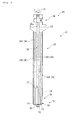
- FIG. 1 A reamer as the hole machining tool according to the exemplary embodiment of the invention is shown in Figs. 1 to 3 .
- the reamer 20, according to this embodiment, has a tool body 21 having a multi-stepped cylindrical shape about an axis line O.
- the front end (lower end in Fig. 1 ) of the tool body 21 becomes a machining section 22 having an approximately cylindrical shape and a guard section 23, having a diameter larger than the machining section 22, is formed on the rear end (upper side in Fig. 1 ) of the tool body 21.
- An attachment section 24 to which a tool holder (not shown) for fitting the reamer 20 to a primary shaft end of a machining tool is formed on the further rear end of the guard section 23.
- a pilot 25 having a diameter smaller than that of the machining section 22 is disposed on the front end surface of the tool body 21.
- a coolant supply hole 26 extending from the attachment section 24 along the axis line O and reaching a portion retreating by about 1/5 of the entire length of the machining section 22 from the front end surface of the tool body 21 is formed in the tool body 21 and a coolant ejecting hole 27 extending from the coolant supply hole 26 to the outside in the diameter direction of the tool body 21 and being open from the outer peripheral surface of the tool body 21 is formed in the tool body 21.
- a recessed portion 30 opened to the front end of the tool body 21 and the outside in the diameter direction is formed on the front end of the tool body 21 (machining section 22).
- a wall surface 30A of the recessed portion 30 close to the rear end of the tool body 21 forms a concave-curved surface shape which is recessed to the inside in the diameter direction of the tool body 21 and the rear end of the tool body 21.
- a coolant discharging hole 28 extending from the coolant ejecting hole 27 to the front end in the diameter direction of the tool body 21 and the rear side in a tool rotation direction T opens in the wall surface 30A.
- the recessed portion 30 in the section perpendicular to the axis line O, the recessed portion 30 forms a concave-curved line shape which is recessed to the inside in the diameter direction of the tool body 21 and extends in parallel to the axis line O to the rear end of the tool body 21.
- the amount of the bottom 30B (portion most recessed to the inside in the diameter direction) of the concave-curved line recessed from the outer peripheral surface of the tool body 21 is about 1/3 of the outer diameter of the tool body 21 (2/3 of the radius of the tool body 21) and the size of the recessed portion 30 in the circumferential direction is about 1/8 of the outer circumference of the tool body 21.
- the length of the recessed portion 30 in the direction of the axis line O is about 1/20 of the entire length of the machining section 22, as shown in Fig. 1 .
- An attachment seat 31 for detachably seating an insert 50, to be described later, is formed on the rear side of the recessed portion 30 in the tool rotation direction T.
- the attachment seat 31 has a wall surface 31A facing the outside in the diameter direction of the tool body 21 and the wall surface 31A is connected to one end (the rear end in the tool rotation direction T) of the concave-curved line forming the recessed portion 30, as shown in Fig. 3 .
- the wall surface 31A of the attachment seat 31 facing the outside in the diameter direction of the tool body 21 is formed so that the distance in the diameter direction from the axis line O increases as it goes to the front side from the rear side in the tool rotation direction T, as shown in Fig. 3 , in the section perpendicular to the axis line O and so that the wall surface 31A extends parallel to the axis line O, as shown in Fig. 2 , in the side view of the tool body 21.
- a clamp screw hole 32 extending in the direction perpendicular to the axis line O is formed in the wall surface 31A.
- a pin hole 33 which opens in the wall surface of the attachment seat 31 facing the front side in the tool rotation direction T and which extends in a direction substantially perpendicular to the direction in which the wall surface 31A facing the outside in the diameter direction of the tool body 21 is formed on the rear side of the attachment seat 31 in the tool rotation direction T.
- a pressing screw hole 34 extending coaxially with the pin hole 33 is formed on the opposite side of the pin hole 33 of the attachment seat 31.
- the pressing screw hole 34 has a diameter larger by one step than that of the pin hole 33 and a female screw is formed on the inner peripheral surface.
- a large-diameter hole 35 which communicates with the pressing screw hole 34 and is opened in the outer peripheral surface of the tool body 21 is formed in the tool body 21.
- a pressing pin 40 having an approximately cylindrical shape is inserted into the pin hole 33 and a pressing surface 40A protruding to the attachment seat 31 toward the front side in the tool rotation direction T is formed at the front end of the pressing pin 40.
- the pressing surface 40A is inclined about the axis line of the pressing pin 40 so as to gradually go to the inside of the pressing pin 40 as it goes to the front end of the pressing pin 40.
- a pressing screw 41 having an approximately cylindrical shape and having a male screw formed on the outer peripheral surface is screwed into the pressing screw hole 34 and the front end surface of the pressing screw 41 abuts the rear end surface of the pressing pin 40.
- An engagement hole (not shown), to engage with a working tool such as a wrench, is formed in the rear end surface of the pressing screw 41 and the engagement hole opens toward the outer peripheral surface of the tool body 21 through the large-diameter hole 35.
- a notch 36 opened toward the outside in the diameter direction of the tool body 21 is formed on the side of the recessed portion 30 close to the rear end of the tool body 21 and a screw through hole 37 extending to the attachment seat 31 is formed in the surface of the notch 36 facing the rear end of the tool body 21.
- An adjustment screw 42 having an approximately cylindrical shape and having a male screw formed on the outer peripheral surface thereof is screwed into the screw through hole 37.
- a plurality of guide pads 38 which is formed of a hard material of which an outer shape is an approximately elliptical panel shape is disposed on the outer periphery of the machining section 22 of the tool body 21 so as to extend parallel to the axis line O and six guide pads 38 are disposed with a constant pitch in the circumferential direction as shown in Fig. 3 in this embodiment. As shown in Fig.
- the guide pad 38A disposed in a portion interfering with the recessed portion 30, the attachment seat 31, and the notch 36 extends to the rear end of the tool body 21 of the notch 36 and the guide pad 38B, disposed in a portion interfering with the large-diameter hole 35, is divided into two portions at the front end and the rear end of the tool body 21 with the large-diameter hole 35 therebetween.
- the other guide pads 38C extend to the front end surface of the tool body 21.
- the insert 50 which is detachably attached to the attachment seat 31 of the tool body 21 will be described.
- the insert 50 has an approximately rectangular plane shape as shown in Figs. 2 and 3 and has two faces facing the thickness direction thereof and four side faces.
- One face facing the thickness direction of the insert 50 becomes a seating surface 51 which is seated on the wall surface 31A of the attachment seat 31 facing the outside in the diameter direction of the tool body 21 toward the inside in the diameter direction of the tool body 21.
- the other face facing the thickness direction becomes a peripheral flank surface 52 toward the outside in the diameter direction of the tool body 21.
- An insertion hole 53 penetrating the insert 50 in the thickness direction is formed in one face (seating surface 51) and the other face (peripheral flank surface 52).
- One side face of the insert 50 becomes the inclined surface 54 toward the front side in the tool rotation direction T and a panel-shaped cutting edge portion 55 formed of a diamond-sintered body is disposed on one end (front end of the tool body 21) of the side face forming the inclined surface 54.
- a peripheral cutting edge 56 is formed at an intersection ridge portion between the cutting edge portion 55 and the other face (peripheral flank surface 52) facing the thickness direction, thereby forming a longitudinal-edge insert 50.
- the inclined surface 54 is disposed so as to intersect the seating surface 51 at an obtuse angle as shown in Fig. 3 .
- a chamfered portion 58 is formed at the intersection between the side face opposed to the front end of the tool body 21 and the other face as the peripheral flank surface 52 and a bevel cutting edge 59 is formed at the intersection ridge portion between the chamfered portion 58 and the cutting edge portion 55. That is, as shown in Fig. 2 , as viewed from the side opposite to the inclined surface 54, the bevel cutting edge 59 inclined to retreat to the inside in the diameter direction of the tool body 21 as it goes to the front end of the tool body 21 is connected to the side of the peripheral cutting edge 56 close to the front end of the tool body 21.
- the side face opposite to the side face as the inclined surface 54 that is, the side face facing the rear side in the tool rotation direction T, becomes a pressed surface 61 abutting the pressing surface of the pressing pin.
- the pressed surface 61 is formed so as to intersect the seating surface 51 at an obtuse angle and so as to protrude to the rear side in the tool rotation direction T as it goes to the outside in the diameter direction of the tool body 21. Accordingly, the section of the insert 50 perpendicular to the axis line O has an approximately trapezoid shape when being attached to the attachment seat 31, as shown in Fig. 3 .
- the peripheral flank surface 52 facing the outside in the diameter direction of the tool body 21 is inclined about the axis line O so as to be directed to the inside in the diameter direction of the tool body 21 as it goes toward the rear end of the tool body 21, as shown in Fig. 2 , as viewed from the side opposite to the inclined surface 54 and the back taper is attached to the peripheral cutting edge 56 formed at the intersection ridge portion between the peripheral flank surface 52 and the cutting edge portion 55 so as to be directed to the inside in the diameter direction of the tool body 21 as it goes to the rear end of the tool body 21.
- the amount of back taper is set in the range of 40 ⁇ m/15 mm to 80 ⁇ m/15 mm and more specifically 60 ⁇ m/15 mm.
- the insert 50 having the above-mentioned configuration is attached to the attachment seat 31 of the tool body 21 as follows.
- the insert 50 is seated on the attachment seat 31 so that the inclined surface side face 54 is directed to the front side in the tool rotation direction T and the one face (seating surface 51) in the thickness direction of the insert 50 abuts the wall surface 31A of the attachment seat 31 facing the outside in the diameter direction of the tool body 21.
- the pressed surface 61 of the insert 50 abuts the pressing surface 40A of the pressing pin 40 and the side face of the insert 50 facing the rear end of the tool body 21 abuts the front end of the adjustment screw 42.
- the insert 50 is attached to the attachment seat 31.
- the reamer 20 constructed by attaching the insert 50 to the attachment seat 31 of the tool body 21 in this way is fitted to the primary shaft end of a machining tool through a tool holder mounted on the attachment section 24, is fed to the front end in the direction of the axis line O with the rotation about the axis line O, is inserted into the pilot hole formed in advance in a workpiece, to cut the inner surface of the pilot hole by the use of the bevel cutting edge 59 and the peripheral cutting edge 56, thereby forming a machined hole having a predetermined inner diameter.
- the coolant supplied from the machining tool is ejected toward the inner surface of the machined hole from the coolant ejecting hole 27 through the coolant supply hole 26 so as to smoothen the sliding between the guide pads 38 and the inner surface of the machined hole and the coolant is discharged toward the insert 50 from the coolant discharging hole 28 to cool the peripheral cutting edge 56 and the bevel cutting edge 59, thereby satisfactorily performing the cutting process.
- the positioning of the insert 50 in the reamer 20 is performed as follows. A working tool is allowed to engage with the engagement hole exposed from the outer peripheral surface of the tool body 21 through the large-diameter hole 35, the pressing screw 41 is inserted thereto, and then the pressing pin 40 is allowed to move to the attachment seat 31.
- the pressing surface 40A presses the pressed surface 61 and thus the insert 50 moves to the front side in the tool rotation direction T along the wall surface 31A of the attachment seat 31 facing the outside in the diameter direction of the tool body 21.
- the wall surface 31A of the attachment seat 31 facing the outside in the diameter direction of the tool body 21 is disposed so that the distance from the axis line O in the diameter direction gradually increases as it goes to the front side from the rear side in the tool rotation direction T, as shown in Fig.
- the insert 50 protrudes to the outside in the diameter direction of the tool body 21. Accordingly, by adjusting the pressing force of the pressing pin 40 on the insert 50 by the use of the pressing screw 41, it is possible to adjust the position of the peripheral cutting edge 56 in the diameter direction of the tool body 21.
- the peripheral flank surface 52 of the insert 50 retreats to the inside in the diameter direction of the tool body 21 as it goes to the rear end of the tool body 21, the back taper is attached to the peripheral cutting edge 56 already, and the amount of back taper does not vary even when the insert 50 moves to the front side in the tool rotation direction T. Accordingly, it is not necessary to adjust the back taper of the peripheral cutting edge 56.
- the reamer 20 according to this embodiment since it is necessary to adjust the position of the peripheral cutting edge 56 in only the diameter direction by operating the pressing screw 41, it is possible to simply and precisely adjust the position of the insert 50.
- the so-called longitudinal-edge insert 50 is attached as the insert 50 having a quadrangular tabular shape, in which the one face in the thickness direction is used as the seating surface 51 facing the inside in the diameter direction of the tool body 21, the other face in the thickness direction is used as the peripheral flank surface 52 facing the outside in the diameter direction of the tool body 21, the side face facing the front side in the tool rotation direction T is used as the inclined surface 54, and the peripheral cutting edge 56 is formed at the intersection ridge portion between the inclined surface 54 and the peripheral flank surface 52.
- the insert 50 can be attached to the tool body 21 in the state where the thickness direction of the insert 50 is approximately matched with the diameter direction of the tool body 21, thereby reducing the portions cut out from the tool body 21 so as to form the attachment seat 31 and reducing the recessed portion 30 located on the front side in the tool rotation direction T of the attachment seat 31. Accordingly, the movement balance and the rigidity of the tool body 21 can be enhanced, thereby preventing the vibration of the tool body 21 and forming a machined hole with high dimensional precision. It is possible to construct an insert type hole machining tool capable of adjusting the diameter thereof in a reamer for forming a machined hole having a small diameter.
- the amount of the bottom 30A (the portion most recessed to the inside in the diameter direction) of the concave-curved line formed by the section of the recessed portion 30 perpendicular to the axis line O recessed from the outer peripheral surface of the tool body 21 is about 1/3 of the outer diameter of the tool body 21 (2/3 of the radius of the tool body 21) and is small relative to the tool body 21.
- two guide pads 38A out of the six guide pads 38 formed on the periphery of the machining section 22 can be formed to extend to the rear end of the tool body 21 from the recessed portion 30 and the attachment seat 31, the guide pad 38B disposed in the portion in which the large-diameter hole 35 is formed can be divided into two portions by the large-diameter hole 35 and can extend to the front end of the tool body 21, and the other three guide pads 35C can be formed to extend to the front end surface of the tool body 21.
- the guide pad 38A disposed from the recessed portion 30 and the attachment seat 31 to the rear end of the tool body 21 can extend to the vicinity of the tool body 21.
- the guide pads 38 can be disposed in this way, the machined hole and the guide pads 38 can be allowed to slide with good balance in the vicinity of the insert 50 for performing the cutting process and the disturbance of the axis line O of the reamer 20 can be surely prevented, thereby forming the machined hole having a high circularity with high dimensional precision. Since a machined hole having a high circularity can be formed, the reamer 20 can be used to machine a machined hole (for example, a cam hole of an engine) which requires a high dimensional tolerance which could not be machined with the known reamer 20, thereby efficiently forming the machined hole.
- a machined hole for example, a cam hole of an engine
- a notch 36 is formed in the portion of the attachment seat 31 close to the rear end of the tool body 21 and the adjustment screw 42 screwed into the screw through hole 37 formed in the surface of the notch 36 facing the rear end of the tool body 21 abuts the side face of the insert 50 facing the rear end of the tool body 21, it is possible to adjust the protrusion amount (advance amount) of the bevel cutting edge 59 of the insert 50 protruding from the front end surface of the tool body 21 toward the front end of the tool body 21.
- the cutting edge portion 55 formed of a diamond-sintered body is formed in the insert 50 and the peripheral cutting edge 56 and the bevel cutting edge 59 are formed in the cutting edge portion 55, it is possible to improve the wear resistance of both the peripheral cutting edge 56 and the bevel cutting edge 59, thereby extending the lifetime of the insert 50.
- a cutting edge portion 55 formed of a diamond-sintered body has approximately a panel shape and the cutting edge portion 55 is stacked on a chamfered portion 58 extending from the bevel cutting edge 59 of the insert 50.
- the re-grinding is performed along the inclined surface 54, thereby reducing the variation in position of the bevel cutting edge 59 in the axial direction. Therefore, by slightly pressing the insert 50, by the use of the adjustment screw 42, after the re-grinding, it is possible to adjust the position of the bevel cutting edge 59 in the axial direction.
- the amount of the cutting edge portion 55, formed of a diamond-sintered body, to be re-ground is small. It is known that the surface roughness of the diamond-sintered body not ground is three times better.
- the insert and the hole machining tool having the insert attached thereto have been described, the invention is not limited to the embodiments, but may be modified in various forms without departing from the technical spirit of the invention.
- the reamer in which the guard section and the attachment section are provided on the rear end of the tool body has been described, the present invention is not limited to this reamer configuration, but may have a reamer configuration in which the tool body has a substantially constant outer diameter over the entire length without the guard section and the rear end portion of the tool body is inserted into a fitting hole formed in a cutting tool.
- the present invention is not limited to it, but the arrangement and number of the guide pads may be appropriately selected in consideration of the cutting condition, etc.
- the pressing pin is provided as the pressing member
- the present invention is not limited to it, but another pressing member such as a wedge member may be provided.
- the adjustment screw is provided as the adjustment member for adjusting the protrusion amount (advance amount) of the bevel cutting edge protruding from the front end surface of the tool body, the present invention is not limited to it, but another adjustment member such as a wedge member may be provided or the adjustment member may not be provided.
- the amount of the back taper provided in the peripheral cutting edge facing the outside in the diameter direction of the tool body is in the range of 40 ⁇ m/15 mm to 80 ⁇ m/15 mm and more specifically 60 ⁇ m/15 mm
- the present invention is not limited to it, but the amount of the back taper may be appropriately set in consideration of the cutting condition, etc.
- the insert has the cutting edge portion formed of a diamond-sintered body
- the insert may have a cutting edge portion integrally formed of cemented carbide or formed of a cBN-sintered body.
Landscapes
- Engineering & Computer Science (AREA)
- Mechanical Engineering (AREA)
- Milling, Broaching, Filing, Reaming, And Others (AREA)
- Drilling And Boring (AREA)
- Crystals, And After-Treatments Of Crystals (AREA)
- Polishing Bodies And Polishing Tools (AREA)
- Drilling Tools (AREA)
Abstract
Description
- The present invention relates to an insert attached to a hole machining tool which is inserted into a pilot hole formed in advance in a workpiece to cut the inner surface of the pilot hole.
- As such a type of hole machining tool, a reamer in which an edge portion having a cutting edge is soldered to a front end of a tool body rotating about an axis line and having a longitudinal cylindrical shape is known. The reamer rotates about the axis line, is fed in the axial direction, is inserted into a pilot hole formed in advance in a workpiece to cut the inner surface of the pilot hole with the cutting edge formed in the edge portion, thereby forming a machined hole having a predetermined inner diameter.
- In such a hole machining tool in which the edge portion is soldered to the tool body, the position of the cutting edge in the diameter direction cannot be adjusted and thus the position of the cutting edge is determined by means of soldering precision. Accordingly, it is not possible to cope with the machining of a hole having a very small dimensional tolerance.
- Therefore, for example, as described in
JP-A-2002-160124 Figs. 7 and8 show an example of the known insert type reamer having the positioning mechanism. - The reamer 1 shown in
Figs. 7 and8 has a tool body 2 rotating about an axis line O and having a longitudinal cylindrical shape. A recessed portion 3 opened to the front end of the tool body 2 and the outside in the diameter direction of the tool body 2 is formed in a front outer periphery of the tool body 2 and anattachment seat 4 is formed on the rear side of the recessed portion 3 in the tool rotation direction T. As shown inFig. 8 , a plurality ofguide pads 5 is disposed on the outer periphery of the tool body 2 with a constant gap in the circumferential direction. A portion of theguide pads 5 interfering with the recessed portion 3 and theattachment seat 4 extend from the recessed portion 3 and theattachment seat 4 to the rear end of the tool body 2 and the other portion of theguide pads 5 extend to the front end of the tool body 2.
A panel-shaped insert 6 having acutting edge 6A is attached to theattachment seat 4 in a state that the thickness direction thereof is matched with the tool rotation direction T, and is fixed thereto with aclamp screw 7. - The
cutting edge 6A of theinsert 6 is directed to the outside in the diameter direction of the tool body 2 and the front end of the tool body 2 and twoadjustment screws insert 6 in the diameter direction, are disposed in the inside of theinsert 6 in the diameter direction of the tool body 2 so as to be arranged in the axial direction O. The adjustment screw located on the rear end of the tool body 2 is afirst adjustment screw 8 and the adjustment screw located on the front end of the tool body 2 is asecond adjustment screw 9. The front end surfaces of the first and second adjustment screws 8 and 9 abut a surface of theinsert 6 facing the inside in the diameter direction of the tool body 2. A receivinghole 10 open to the outside in the diameter direction of the tool body 2 is formed on the side of theattachment seat 4 close to the rear end of the tool body 2 and anadjustment wedge 11 for adjusting the position of theinsert 6 in the axial direction O is inserted into thereceiving hole 10. - The reamer 1 having the above-mentioned configuration is fitted to a primary shaft end of a machining tool, is fed to the front end in the axial direction O with the rotation about the axis line O, is inserted into a pilot hole formed in advance in a workpiece to cut the inner surface of the pilot hole with the
cutting edge 6A of theinsert 6, thereby forming a machined hole having a predetermined inner diameter.
At the time of performing the cutting, the guide pads 5 slide on the inner surface of the machined hole and thus prevent the fluctuation of the axis line O of the reamer 1, thereby enhancing the dimensional precision. - In the reamer 1 having the above-mentioned configuration, the inclination angle (back taper) of the
cutting edge 6A formed in theinsert 6 about the axis line O and the position of thecutting edge 6A in the diameter direction of the tool body 2 can be adjusted using thefirst adjustment screw 8 and thesecond adjustment screw 9, thereby forming the machined hole having a predetermined inner diameter with excellent dimensional precision. In addition, it is possible to cope with a very small dimensional tolerance of a machined hole. By appropriately attaching the back taper, it is possible to prevent unnecessary contact between the inner surface of the machined hole and theinsert 6, thereby reducing cutting resistance. - However, in the reamer 1, since the panel-
shaped insert 6 is attached in a state where the thickness direction thereof is matched with the tool rotation direction, it is necessary to open the large recessed portion 3 located on the front side of theattachment seat 4 in the tool rotation direction T. For example, in the reamer 1 shown inFig. 8 , the recessed amount of the portion recessed to the inside in the diameter direction of the tool body 2 from a section of the recessed portion 3 perpendicular to the axis line O is about 2/5 of the outer diameter of the tool body 2 (4/5 of the radius of the tool body 2) and the circumferential size of the recessed portion 3 is in the range of 1/5 to 1/4 of the circumference of the tool body 2. Since the recessed portion 3 occupies a large portion of the tool body 2, the weight balance is poor in the section perpendicular to the axis line O and the movement at the time of rotating the tool body 2 about the axis line O at a high speed is not balanced. Accordingly, the position of the axis line O is disturbed, whereby a machined hole having a high circularity with excellent dimensional precision is not formed. - In order to form the large recessed portion 3 and the
attachment seat 4, a plurality ofguide pads 5 extend to the rear end of the tool body 2 from the recessed portion 3 and theguide pads 5 do not slide on the machined hole with good balance on the front end of the tool body 2, thereby disturbing the axis line O of the reamer 1. When the recessed portion 3 is large along the axis line O direction, theguide pads 5 are shortened, thereby increasing the disturbance of the axis line O. - It is necessary to form the recessed portion 3, the
clamp screw hole 12 into which aclamp screw 7 is screwed,adjustment screw holes adjustment screws hole 10 for receiving theadjustment wedge 11 in the front end portion of the tool body 2 and portions of the tool body 2 to be cut out increase, thereby reducing the rigidity of the tool body 2. Accordingly, at the time of rotating the tool body 2 at a high speed, vibration may occur. Specifically, when the reamer 1 has a small diameter, there is no space for forming the recessed portion 3, theclamp screw hole 12, theadjustment screw holes 13, and the receivinghole 10, thereby not providing the insert type reamer having the above-mentioned adjustment mechanism. - The adjustment mechanism for adjusting the back taper and the adjustment mechanism for adjusting the position in the diameter direction of the tool body 2 are embodied by the first and
second adjustment screws insert 6 and thus the positioning of theinsert 6 could not be performed simply and precisely. - The invention is contrived to solve the above-mentioned problems. An object of the invention is to provide an insert which is attached to a tool body of a hole machining tool, which can enhance movement balance and rigidity of the tool body by reducing the portions cut out from the tool body, and which can simply adjust the position of the insert with high precision.
- In order to achieve the above-mentioned object, according to an aspect of the invention, there is provided an insert attached to a hole machining tool having a tool body rotating about an axis line, in which a recessed portion which is open to the front end of the tool body and the outside in a diameter direction of the tool body is formed, an attachment seat is formed on the rear side of the recessed portion in a tool rotation direction, and a pressing member for pressing a pressed surface of the insert to adjust a position of a peripheral cutting edge in the diameter direction of the tool body is disposed on the rear side of the attachment seat in the tool rotation direction, wherein one surface in the thickness direction of the insert having a panel shape becomes a seating surface which is seated on a wall surface of the attachment seat, facing the outside in the diameter direction, disposed in the tool body and the other surface in the thickness direction becomes a peripheral flank surface facing the outside in the diameter direction of the tool body, wherein a surface of the insert facing the rear side in the tool rotation direction becomes the pressed surface in a state that the insert attached to the attachment seat, a side surface of the insert facing the front side in the tool rotation direction becomes an inclined surface, and a peripheral cutting edge is formed at a ridge portion of the inclined surface on the outside in the diameter direction of the tool body, and wherein the pressed surface intersects the seating surface at an obtuse angle.
- In the insert having the above-mentioned configuration, it is possible to adjust the position of the peripheral cutting edge of the insert disposed on the outside in the diameter direction of the tool body by moving the insert to the front side in the tool rotation direction by the use of the pressing member disposed on the rear side in the tool rotation direction. That is, the pressed surface of the insert intersects the seating surface at an obtuse angle and gradually protrudes to the rear side in the tool rotation direction as it goes to the outside of the diameter direction of the tool body. Accordingly, by pressing the pressed surface, the insert moves to the front side in the tool rotation direction along the wall surface of the attachment seat facing the outside in the diameter direction of the tool body.
- Since a so-called longitudinal insert having a panel shape, in which the thickness direction thereof is matched with the diameter direction of the tool body, the surface thereof facing the front side in the tool rotation direction becomes the inclined surface, and the peripheral cutting edge is formed in the ridge portion of the inclined surface on the outside in the diameter direction of the tool body, is attached as the insert, it is possible to seat the insert in a state where the thickness direction thereof is approximately matched with the diameter direction of the tool body, to reduce the portions cut out from the tool body so as to form the attachment seat, and to reduce the size of the recessed portion located on the front side of the attachment seat in the tool rotation direction.
- Since the pressing member can be disposed on the rear side of the attachment seat in the tool rotation direction, it is possible to reduce the portions cut out from the tool body. Therefore, it is possible to enhance the movement balance and the rigidity of the tool body and to prevent the vibration of the tool body, thereby forming a machined hole with high precision. Even with a hole machining tool for forming a machined hole with a small diameter, it is possible to construct a hole machining tool with an insert of which the diameter can be adjusted.
- The portions for forming the recessed portion and the attachment seat can be reduced in size. Accordingly, for example, when the guide pads are disposed on the outer periphery of the tool body, the portions interfering with the recessed portion and the attachment seat are reduced and the guide pads can be disposed to the vicinity of the front end of the tool body with good balance. In addition, the disturbance of the axis line of the tool body can be satisfactorily prevented by means of sliding between the machined hole and the guide pads, thereby forming a machined hole having a high circularity.
- By using an insert having a cutting edge portion formed of a diamond-sintered body and having the peripheral cutting edge formed in the cutting edge portion as the above-mentioned insert, it is possible to enhance the wear resistance of the cutting edge, thereby extending the lifetime of the insert.
- By forming the cutting edge portion in a panel shape and disposing the thickness direction thereof toward the flank surface extending from the bevel cutting edge, the re-grinding is performed along the inclined surface, thereby greatly reducing the variation in position in the axial direction of the bevel cutting edge. Therefore, it is possible to simply adjust the position of the bevel cutting edge in the axial direction after the re-grinding.
- By fitting the back taper to the peripheral cutting edge so that it gradually retreats to the inside in the diameter direction of the tool body as it goes to the rear end of the tool body, it is not necessary to adjust the back taper of the peripheral cutting edge. Therefore, since only the position of the peripheral cutting edge in the diameter direction can be adjusted by operating the pressing member, it is possible to simply adjust the position of the insert with high precision.
- According to the invention, it is possible to provide an insert which is attached to a tool body of a hole machining tool, which can enhance movement balance and rigidity of the tool body by reducing portions cut out from the tool body, and which can simply adjust the position of the insert with high precision.
- Hereinafter, an insert and a hole machining tool having the insert attached thereto according to a first embodiment of the invention will be described with reference to the accompanying drawings. A reamer as the hole machining tool according to the exemplary embodiment of the invention is shown in
Figs. 1 to 3 .
Thereamer 20, according to this embodiment, has atool body 21 having a multi-stepped cylindrical shape about an axis line O. The front end (lower end inFig. 1 ) of thetool body 21 becomes amachining section 22 having an approximately cylindrical shape and aguard section 23, having a diameter larger than themachining section 22, is formed on the rear end (upper side inFig. 1 ) of thetool body 21. Anattachment section 24 to which a tool holder (not shown) for fitting thereamer 20 to a primary shaft end of a machining tool is formed on the further rear end of theguard section 23. - A
pilot 25 having a diameter smaller than that of themachining section 22 is disposed on the front end surface of thetool body 21.
Acoolant supply hole 26 extending from theattachment section 24 along the axis line O and reaching a portion retreating by about 1/5 of the entire length of themachining section 22 from the front end surface of thetool body 21 is formed in thetool body 21 and acoolant ejecting hole 27 extending from thecoolant supply hole 26 to the outside in the diameter direction of thetool body 21 and being open from the outer peripheral surface of thetool body 21 is formed in thetool body 21. - A
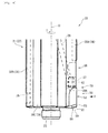
recessed portion 30 opened to the front end of thetool body 21 and the outside in the diameter direction is formed on the front end of the tool body 21 (machining section 22). As shown inFig. 2 , awall surface 30A of therecessed portion 30 close to the rear end of thetool body 21 forms a concave-curved surface shape which is recessed to the inside in the diameter direction of thetool body 21 and the rear end of thetool body 21. Acoolant discharging hole 28 extending from thecoolant ejecting hole 27 to the front end in the diameter direction of thetool body 21 and the rear side in a tool rotation direction T opens in thewall surface 30A. - In this embodiment, as shown in
Fig. 3 , in the section perpendicular to the axis line O, the recessedportion 30 forms a concave-curved line shape which is recessed to the inside in the diameter direction of thetool body 21 and extends in parallel to the axis line O to the rear end of thetool body 21. The amount of the bottom 30B (portion most recessed to the inside in the diameter direction) of the concave-curved line recessed from the outer peripheral surface of thetool body 21 is about 1/3 of the outer diameter of the tool body 21 (2/3 of the radius of the tool body 21) and the size of the recessedportion 30 in the circumferential direction is about 1/8 of the outer circumference of thetool body 21. The length of the recessedportion 30 in the direction of the axis line O is about 1/20 of the entire length of themachining section 22, as shown inFig. 1 . - An
attachment seat 31 for detachably seating aninsert 50, to be described later, is formed on the rear side of the recessedportion 30 in the tool rotation direction T. Theattachment seat 31 has awall surface 31A facing the outside in the diameter direction of thetool body 21 and thewall surface 31A is connected to one end (the rear end in the tool rotation direction T) of the concave-curved line forming the recessedportion 30, as shown inFig. 3 . - The
wall surface 31A of theattachment seat 31 facing the outside in the diameter direction of thetool body 21 is formed so that the distance in the diameter direction from the axis line O increases as it goes to the front side from the rear side in the tool rotation direction T, as shown inFig. 3 , in the section perpendicular to the axis line O and so that thewall surface 31A extends parallel to the axis line O, as shown inFig. 2 , in the side view of thetool body 21. Aclamp screw hole 32 extending in the direction perpendicular to the axis line O is formed in thewall surface 31A. - A pin hole 33 which opens in the wall surface of the
attachment seat 31 facing the front side in the tool rotation direction T and which extends in a direction substantially perpendicular to the direction in which thewall surface 31A facing the outside in the diameter direction of thetool body 21 is formed on the rear side of theattachment seat 31 in the tool rotation direction T. Apressing screw hole 34 extending coaxially with the pin hole 33 is formed on the opposite side of the pin hole 33 of theattachment seat 31. Thepressing screw hole 34 has a diameter larger by one step than that of the pin hole 33 and a female screw is formed on the inner peripheral surface. A large-diameter hole 35 which communicates with thepressing screw hole 34 and is opened in the outer peripheral surface of thetool body 21 is formed in thetool body 21. - A
pressing pin 40 having an approximately cylindrical shape is inserted into the pin hole 33 and apressing surface 40A protruding to theattachment seat 31 toward the front side in the tool rotation direction T is formed at the front end of thepressing pin 40. Thepressing surface 40A is inclined about the axis line of thepressing pin 40 so as to gradually go to the inside of thepressing pin 40 as it goes to the front end of thepressing pin 40.
Apressing screw 41 having an approximately cylindrical shape and having a male screw formed on the outer peripheral surface is screwed into thepressing screw hole 34 and the front end surface of thepressing screw 41 abuts the rear end surface of thepressing pin 40. An engagement hole (not shown), to engage with a working tool such as a wrench, is formed in the rear end surface of thepressing screw 41 and the engagement hole opens toward the outer peripheral surface of thetool body 21 through the large-diameter hole 35. - A
notch 36 opened toward the outside in the diameter direction of thetool body 21 is formed on the side of the recessedportion 30 close to the rear end of thetool body 21 and a screw throughhole 37 extending to theattachment seat 31 is formed in the surface of thenotch 36 facing the rear end of thetool body 21. Anadjustment screw 42 having an approximately cylindrical shape and having a male screw formed on the outer peripheral surface thereof is screwed into the screw throughhole 37. - A plurality of
guide pads 38 which is formed of a hard material of which an outer shape is an approximately elliptical panel shape is disposed on the outer periphery of themachining section 22 of thetool body 21 so as to extend parallel to the axis line O and sixguide pads 38 are disposed with a constant pitch in the circumferential direction as shown inFig. 3 in this embodiment. As shown inFig. 1 , theguide pad 38A disposed in a portion interfering with the recessedportion 30, theattachment seat 31, and thenotch 36 extends to the rear end of thetool body 21 of thenotch 36 and theguide pad 38B, disposed in a portion interfering with the large-diameter hole 35, is divided into two portions at the front end and the rear end of thetool body 21 with the large-diameter hole 35 therebetween. Theother guide pads 38C extend to the front end surface of thetool body 21. - Next, the
insert 50 which is detachably attached to theattachment seat 31 of thetool body 21 will be described.
Theinsert 50 has an approximately rectangular plane shape as shown inFigs. 2 and3 and has two faces facing the thickness direction thereof and four side faces. One face facing the thickness direction of theinsert 50 becomes aseating surface 51 which is seated on thewall surface 31A of theattachment seat 31 facing the outside in the diameter direction of thetool body 21 toward the inside in the diameter direction of thetool body 21. The other face facing the thickness direction becomes aperipheral flank surface 52 toward the outside in the diameter direction of thetool body 21.
Aninsertion hole 53 penetrating theinsert 50 in the thickness direction is formed in one face (seating surface 51) and the other face (peripheral flank surface 52). - One side face of the
insert 50 becomes theinclined surface 54 toward the front side in the tool rotation direction T and a panel-shapedcutting edge portion 55 formed of a diamond-sintered body is disposed on one end (front end of the tool body 21) of the side face forming theinclined surface 54. Aperipheral cutting edge 56 is formed at an intersection ridge portion between the cuttingedge portion 55 and the other face (peripheral flank surface 52) facing the thickness direction, thereby forming a longitudinal-edge insert 50. Theinclined surface 54 is disposed so as to intersect theseating surface 51 at an obtuse angle as shown inFig. 3 . - In the state that the insert is attached to the
attachment seat 31, a chamferedportion 58 is formed at the intersection between the side face opposed to the front end of thetool body 21 and the other face as theperipheral flank surface 52 and abevel cutting edge 59 is formed at the intersection ridge portion between the chamferedportion 58 and thecutting edge portion 55.
That is, as shown inFig. 2 , as viewed from the side opposite to theinclined surface 54, thebevel cutting edge 59 inclined to retreat to the inside in the diameter direction of thetool body 21 as it goes to the front end of thetool body 21 is connected to the side of theperipheral cutting edge 56 close to the front end of thetool body 21. - The side face opposite to the side face as the
inclined surface 54, that is, the side face facing the rear side in the tool rotation direction T, becomes apressed surface 61 abutting the pressing surface of the pressing pin. The pressedsurface 61 is formed so as to intersect theseating surface 51 at an obtuse angle and so as to protrude to the rear side in the tool rotation direction T as it goes to the outside in the diameter direction of thetool body 21. Accordingly, the section of theinsert 50 perpendicular to the axis line O has an approximately trapezoid shape when being attached to theattachment seat 31, as shown inFig. 3 . - The
peripheral flank surface 52 facing the outside in the diameter direction of thetool body 21 is inclined about the axis line O so as to be directed to the inside in the diameter direction of thetool body 21 as it goes toward the rear end of thetool body 21, as shown inFig. 2 , as viewed from the side opposite to theinclined surface 54 and the back taper is attached to theperipheral cutting edge 56 formed at the intersection ridge portion between theperipheral flank surface 52 and thecutting edge portion 55 so as to be directed to the inside in the diameter direction of thetool body 21 as it goes to the rear end of thetool body 21. In this embodiment, the amount of back taper is set in the range of 40 µm/15 mm to 80 µm/15 mm and more specifically 60 µm/15 mm. - The
insert 50 having the above-mentioned configuration is attached to theattachment seat 31 of thetool body 21 as follows. Theinsert 50 is seated on theattachment seat 31 so that the inclined surface side face 54 is directed to the front side in the tool rotation direction T and the one face (seating surface 51) in the thickness direction of theinsert 50 abuts thewall surface 31A of theattachment seat 31 facing the outside in the diameter direction of thetool body 21. Here, the pressedsurface 61 of theinsert 50 abuts thepressing surface 40A of thepressing pin 40 and the side face of theinsert 50 facing the rear end of thetool body 21 abuts the front end of theadjustment screw 42. In this state, by screwing theclamp screw 70 inserted into theinsertion hole 53 into theclamp screw hole 32 opened in thewall surface 31A of theattachment seat 31 facing the outside in the diameter direction of thetool body 21, theinsert 50 is attached to theattachment seat 31. - The
reamer 20 constructed by attaching theinsert 50 to theattachment seat 31 of thetool body 21 in this way is fitted to the primary shaft end of a machining tool through a tool holder mounted on theattachment section 24, is fed to the front end in the direction of the axis line O with the rotation about the axis line O, is inserted into the pilot hole formed in advance in a workpiece, to cut the inner surface of the pilot hole by the use of thebevel cutting edge 59 and theperipheral cutting edge 56, thereby forming a machined hole having a predetermined inner diameter. - At the time of performing the cutting process, the coolant supplied from the machining tool is ejected toward the inner surface of the machined hole from the
coolant ejecting hole 27 through thecoolant supply hole 26 so as to smoothen the sliding between theguide pads 38 and the inner surface of the machined hole and the coolant is discharged toward theinsert 50 from thecoolant discharging hole 28 to cool theperipheral cutting edge 56 and thebevel cutting edge 59, thereby satisfactorily performing the cutting process. - Here, the positioning of the
insert 50 in thereamer 20 is performed as follows. A working tool is allowed to engage with the engagement hole exposed from the outer peripheral surface of thetool body 21 through the large-diameter hole 35, thepressing screw 41 is inserted thereto, and then thepressing pin 40 is allowed to move to theattachment seat 31. Then, since the pressedsurface 61 of theinsert 50 protrudes to the rear side in the tool rotation direction T as it goes to the outside in the diameter direction of thetool body 21 so as to intersect theseating surface 51 abutting thewall surface 31A at an obtuse angle, thepressing surface 40A presses the pressedsurface 61 and thus theinsert 50 moves to the front side in the tool rotation direction T along thewall surface 31A of theattachment seat 31 facing the outside in the diameter direction of thetool body 21. Here, since thewall surface 31A of theattachment seat 31 facing the outside in the diameter direction of thetool body 21 is disposed so that the distance from the axis line O in the diameter direction gradually increases as it goes to the front side from the rear side in the tool rotation direction T, as shown inFig. 3 , in the section perpendicular to the axis line O, theinsert 50 protrudes to the outside in the diameter direction of thetool body 21.
Accordingly, by adjusting the pressing force of thepressing pin 40 on theinsert 50 by the use of thepressing screw 41, it is possible to adjust the position of theperipheral cutting edge 56 in the diameter direction of thetool body 21. - The
peripheral flank surface 52 of theinsert 50 retreats to the inside in the diameter direction of thetool body 21 as it goes to the rear end of thetool body 21, the back taper is attached to theperipheral cutting edge 56 already, and the amount of back taper does not vary even when theinsert 50 moves to the front side in the tool rotation direction T. Accordingly, it is not necessary to adjust the back taper of theperipheral cutting edge 56.
In this way, in thereamer 20 according to this embodiment, since it is necessary to adjust the position of theperipheral cutting edge 56 in only the diameter direction by operating thepressing screw 41, it is possible to simply and precisely adjust the position of theinsert 50. - The so-called longitudinal-
edge insert 50 is attached as theinsert 50 having a quadrangular tabular shape, in which the one face in the thickness direction is used as theseating surface 51 facing the inside in the diameter direction of thetool body 21, the other face in the thickness direction is used as theperipheral flank surface 52 facing the outside in the diameter direction of thetool body 21, the side face facing the front side in the tool rotation direction T is used as theinclined surface 54, and theperipheral cutting edge 56 is formed at the intersection ridge portion between theinclined surface 54 and theperipheral flank surface 52. Accordingly, theinsert 50 can be attached to thetool body 21 in the state where the thickness direction of theinsert 50 is approximately matched with the diameter direction of thetool body 21, thereby reducing the portions cut out from thetool body 21 so as to form theattachment seat 31 and reducing the recessedportion 30 located on the front side in the tool rotation direction T of theattachment seat 31. Accordingly, the movement balance and the rigidity of thetool body 21 can be enhanced, thereby preventing the vibration of thetool body 21 and forming a machined hole with high dimensional precision. It is possible to construct an insert type hole machining tool capable of adjusting the diameter thereof in a reamer for forming a machined hole having a small diameter. - Here, in this embodiment, the amount of the bottom 30A (the portion most recessed to the inside in the diameter direction) of the concave-curved line formed by the section of the recessed
portion 30 perpendicular to the axis line O recessed from the outer peripheral surface of thetool body 21 is about 1/3 of the outer diameter of the tool body 21 (2/3 of the radius of the tool body 21) and is small relative to thetool body 21. Accordingly, twoguide pads 38A out of the sixguide pads 38 formed on the periphery of themachining section 22 can be formed to extend to the rear end of thetool body 21 from the recessedportion 30 and theattachment seat 31, theguide pad 38B disposed in the portion in which the large-diameter hole 35 is formed can be divided into two portions by the large-diameter hole 35 and can extend to the front end of thetool body 21, and the other three guide pads 35C can be formed to extend to the front end surface of thetool body 21.
Since the length of the recessedportion 30 in the direction of the axis line O is 1/20 of the entire length of themachining section 22, theguide pad 38A disposed from the recessedportion 30 and theattachment seat 31 to the rear end of thetool body 21 can extend to the vicinity of thetool body 21. - Since the
guide pads 38 can be disposed in this way, the machined hole and theguide pads 38 can be allowed to slide with good balance in the vicinity of theinsert 50 for performing the cutting process and the disturbance of the axis line O of thereamer 20 can be surely prevented, thereby forming the machined hole having a high circularity with high dimensional precision. Since a machined hole having a high circularity can be formed, thereamer 20 can be used to machine a machined hole (for example, a cam hole of an engine) which requires a high dimensional tolerance which could not be machined with the knownreamer 20, thereby efficiently forming the machined hole. - Since a
notch 36 is formed in the portion of theattachment seat 31 close to the rear end of thetool body 21 and theadjustment screw 42 screwed into the screw throughhole 37 formed in the surface of thenotch 36 facing the rear end of thetool body 21 abuts the side face of theinsert 50 facing the rear end of thetool body 21, it is possible to adjust the protrusion amount (advance amount) of thebevel cutting edge 59 of theinsert 50 protruding from the front end surface of thetool body 21 toward the front end of thetool body 21. - Since the
cutting edge portion 55 formed of a diamond-sintered body is formed in theinsert 50 and theperipheral cutting edge 56 and thebevel cutting edge 59 are formed in thecutting edge portion 55, it is possible to improve the wear resistance of both theperipheral cutting edge 56 and thebevel cutting edge 59, thereby extending the lifetime of theinsert 50. - An insert and a hole machining tool having the insert attached thereto according to a second embodiment of the invention will be described now with reference to
Figs. 4 to 6 . The same elements as in the first embodiment are referenced by the same reference numerals or signs and detailed description thereof will be omitted. - As shown in
Figs. 4 and6 , in aninsert 50 according to the second embodiment, acutting edge portion 55 formed of a diamond-sintered body has approximately a panel shape and thecutting edge portion 55 is stacked on a chamferedportion 58 extending from thebevel cutting edge 59 of theinsert 50. - In the hole machining tool having this configuration, when the
bevel cutting edge 59 and theperipheral cutting edge 56 are worn and need be to re-ground, the re-grinding is performed along theinclined surface 54, thereby reducing the variation in position of thebevel cutting edge 59 in the axial direction. Therefore, by slightly pressing theinsert 50, by the use of theadjustment screw 42, after the re-grinding, it is possible to adjust the position of thebevel cutting edge 59 in the axial direction. The amount of thecutting edge portion 55, formed of a diamond-sintered body, to be re-ground is small.
It is known that the surface roughness of the diamond-sintered body not ground is three times better. In this embodiment, since a portion of thecutting edge portion 55 having good surface roughness is disposed in the flank surface extending from thebevel cutting edge 59 and thus the frictional resistance is reduced, the wear of thecutting edge portion 55 is suppressed, thereby extending the lifetime of theinsert 50. - Although the insert and the hole machining tool having the insert attached thereto according to the embodiments of the invention have been described, the invention is not limited to the embodiments, but may be modified in various forms without departing from the technical spirit of the invention.
For example, although the reamer in which the guard section and the attachment section are provided on the rear end of the tool body has been described, the present invention is not limited to this reamer configuration, but may have a reamer configuration in which the tool body has a substantially constant outer diameter over the entire length without the guard section and the rear end portion of the tool body is inserted into a fitting hole formed in a cutting tool. - Although it has been described that 6 guide pads are disposed with a constant pitch in the circumferential direction, the present invention is not limited to it, but the arrangement and number of the guide pads may be appropriately selected in consideration of the cutting condition, etc.
Although it has been described that the pressing pin is provided as the pressing member, the present invention is not limited to it, but another pressing member such as a wedge member may be provided.
Although it has been described that the adjustment screw is provided as the adjustment member for adjusting the protrusion amount (advance amount) of the bevel cutting edge protruding from the front end surface of the tool body, the present invention is not limited to it, but another adjustment member such as a wedge member may be provided or the adjustment member may not be provided. - Although it has been described that the amount of the back taper provided in the peripheral cutting edge facing the outside in the diameter direction of the tool body is in the range of 40 µm/15 mm to 80 µm/15 mm and more specifically 60 µm/15 mm, the present invention is not limited to it, but the amount of the back taper may be appropriately set in consideration of the cutting condition, etc. However, it is preferable that, by setting the amount of back taper in the above-mentioned range, since it is possible to satisfactorily prevent the inner surface of the machined hole and the rear end portion of the peripheral cutting edge from sliding and thus to smoothly finish the inner surface of the machined hole.
- Although it has been described that the insert has the cutting edge portion formed of a diamond-sintered body, the insert may have a cutting edge portion integrally formed of cemented carbide or formed of a cBN-sintered body.
-
- [
Fig. 1] Fig. 1 is a side view of an insert according to a first embodiment of the invention and a reamer having the insert attached thereto. - [
Fig. 2] Fig. 2 is an enlarged partial sectional view of a front end portion of the reamer shown inFig. 1 . - [
Fig. 3] Fig. 3 is a sectional view of the reamer shown inFig. 1 . - [
Fig. 4] Fig. 4 is an enlarged partial sectional view of an insert according to a second embodiment of the invention and a front end portion of a reamer having the insert attached thereto. - [
Fig. 5] Fig. 5 is a sectional view of the reamer shown inFig. 4 . - [
Fig. 6] Fig. 6 is a view as viewed in a direction of arrow Y inFig. 4 . - [
Fig. 7] Fig. 7 is an enlarged partial sectional view of a front end portion of a known reamer. - [
Fig. 8] Fig. 8 is a sectional view taken along line z-z ofFig. 7 . -
- 20: REAMER (HOLE MACHINING TOOL)
- 21: TOOL BODY
- 30: RECESSED PORTION
- 31: ATTACHMENT SEAT
- 31B: WALL SURFACE FACING OUTSIDE IN DIAMETER DIRECTION OF TOOL BODY
- 32: CLAMP SCREW HOLE
- 36: NOTCH
- 40: PRESSING PIN (PRESSING MEMBER)
- 40A: PRESSING SURFACE
- 41: PRESSING SCREW
- 42: ADJUSTMENT SCREW (ADJSUTMENT MEMBER)
- 50: INSERT
- 51: SEATING SURFACE
- 54: INCLINED SURFACE
- 55: CUTTING EDGE PORTION
- 56: PERIPHERAL CUTTING EDGE
- 59: BEVEL CUTTING EDGE
- 61: PRESSED SURFACE
- 70: CLAMP SCREW
Claims (5)
- An insert attached to a hole machining tool having a tool body rotating about an axis line, in which a recessed portion which is open to the front end of the tool body and the outside in a diameter direction of the tool body is formed, an attachment seat is formed on the rear side of the recessed portion in a tool rotation direction, and a pressing member for pressing a pressed surface of the insert to adjust a position of a peripheral cutting edge in the diameter direction of the tool body is disposed on the rear side of the attachment seat in the tool rotation direction,
wherein one surface in the thickness direction of the insert having a panel shape becomes a seating surface which is seated on a wall surface of the attachment seat, facing the outside in the diameter direction, disposed in the tool body and the other surface in the thickness direction becomes a peripheral flank surface facing the outside in the diameter direction of the tool body,
wherein a surface of the insert facing the rear side in the tool rotation direction becomes the pressed surface in a state that the insert is attached to the attachment seat, a side surface of the insert facing the front side in the tool rotation direction becomes an inclined surface, and a peripheral cutting edge is formed at a ridge portion of the inclined surface on the outside in the diameter direction of the tool body, and
wherein the pressed surface intersects the seating surface at an obtuse angle. - The insert according to Claim 1, wherein one end of the inclined surface is provided with a cutting edge portion formed of a diamond-sintered body and the peripheral cutting edge is formed in the cutting edge portion.
- The insert according to Claim 2, wherein a bevel cutting edge is formed at the ridge portion of the inclined surface close to the front end of the tool body and the peripheral cutting edge and the bevel cutting edge are formed in the cutting edge portion.
- The insert according to Claim 3, wherein the cutting edge portion has a panel shape and the thickness direction thereof is directed to a flank surface extending from the bevel cutting edge.
- The insert according to any one of Claims 1 to 4, wherein, in a state that the insert is attached to the attachment seat of the tool body, a back taper is fitted to the peripheral cutting edge so as to gradually retreat to the inside in the diameter direction of the tool body as it goes to the rear end of the tool body.
Priority Applications (1)
| Application Number | Priority Date | Filing Date | Title |
|---|---|---|---|
| PL09171082T PL2130634T3 (en) | 2006-06-05 | 2007-05-22 | Insert |
Applications Claiming Priority (3)
| Application Number | Priority Date | Filing Date | Title |
|---|---|---|---|
| JP2006156367 | 2006-06-05 | ||
| JP2007038308A JP4816496B2 (en) | 2006-06-05 | 2007-02-19 | Drilling tool |
| EP07010176A EP1864738B1 (en) | 2006-06-05 | 2007-05-22 | Hole machining tool |
Related Parent Applications (2)
| Application Number | Title | Priority Date | Filing Date |
|---|---|---|---|
| EP07010176A Division EP1864738B1 (en) | 2006-06-05 | 2007-05-22 | Hole machining tool |
| EP07010176.1 Division | 2007-05-22 |
Publications (3)
| Publication Number | Publication Date |
|---|---|
| EP2130634A2 true EP2130634A2 (en) | 2009-12-09 |
| EP2130634A3 EP2130634A3 (en) | 2012-03-14 |
| EP2130634B1 EP2130634B1 (en) | 2015-03-25 |
Family
ID=38477052
Family Applications (2)
| Application Number | Title | Priority Date | Filing Date |
|---|---|---|---|
| EP09171082.2A Not-in-force EP2130634B1 (en) | 2006-06-05 | 2007-05-22 | Insert |
| EP07010176A Not-in-force EP1864738B1 (en) | 2006-06-05 | 2007-05-22 | Hole machining tool |
Family Applications After (1)
| Application Number | Title | Priority Date | Filing Date |
|---|---|---|---|
| EP07010176A Not-in-force EP1864738B1 (en) | 2006-06-05 | 2007-05-22 | Hole machining tool |
Country Status (8)
| Country | Link |
|---|---|
| US (1) | US7862266B2 (en) |
| EP (2) | EP2130634B1 (en) |
| JP (1) | JP4816496B2 (en) |
| KR (2) | KR101146386B1 (en) |
| AT (1) | ATE480358T1 (en) |
| DE (1) | DE602007008975D1 (en) |
| ES (1) | ES2537970T3 (en) |
| PL (1) | PL2130634T3 (en) |
Families Citing this family (9)
| Publication number | Priority date | Publication date | Assignee | Title |
|---|---|---|---|---|
| US8641334B2 (en) * | 2006-06-05 | 2014-02-04 | Mitsubishi Materials Corporation | Insert |
| DE102008045327B3 (en) * | 2008-08-21 | 2010-02-18 | MAPAL Fabrik für Präzisionswerkzeuge Dr. Kress KG | reamer |
| JP5572640B2 (en) | 2009-02-24 | 2014-08-13 | コメート グループ ゲーエムベーハー | Machine tool with adjustable plate element |
| SE532924C2 (en) | 2009-03-03 | 2010-05-11 | Seco Tools Ab | Rotary tools comprising a plurality of elongate members and a support |
| US20120121348A1 (en) * | 2010-11-15 | 2012-05-17 | Daimler Ag | Boring tool and method for cylinder bores |
| CN102151857A (en) * | 2011-01-21 | 2011-08-17 | 宁波华星新能源有限公司 | Fine-tuning knife |
| DE102012018643A1 (en) | 2012-09-17 | 2014-04-10 | MAPAL Fabrik für Präzisionswerkzeuge Dr. Kress KG | Tool for machining workpieces |
| JP2017042870A (en) * | 2015-08-26 | 2017-03-02 | アイシン・エィ・ダブリュ株式会社 | Reamer |
| CN111215698B (en) * | 2020-03-18 | 2024-06-14 | 上海新山田精密刀具有限公司 | A high-precision reamer capable of bidirectionally adjusting diameter |
Citations (1)
| Publication number | Priority date | Publication date | Assignee | Title |
|---|---|---|---|---|
| JP2002160124A (en) | 2000-11-24 | 2002-06-04 | Mitsubishi Materials Corp | Indexable reamer |
Family Cites Families (23)
| Publication number | Priority date | Publication date | Assignee | Title |
|---|---|---|---|---|
| DE2948250A1 (en) * | 1979-11-30 | 1981-07-23 | August Beck GmbH & Co, 7472 Winterlingen | REAMER WITH A FLAT RECTANGULAR INSERT |
| US4353669A (en) * | 1980-10-20 | 1982-10-12 | Georg Striegl | Device for machine reamer |
| DE3232804C1 (en) * | 1982-09-03 | 1991-04-18 | Mapal Fabrik für Präzisionswerkzeuge Dr.Kress KG, 7080 Aalen | One-knife reamer |
| DE3520179C2 (en) * | 1985-06-05 | 1994-05-11 | Frits Weyler | Machine reamer with adjustable insert |
| FR2633856B1 (en) | 1988-07-08 | 1994-05-20 | Planche Simon | TOOL WITH REPORTED LONGITUDINAL BLADE AND MORE PARTICULARLY BUT NOT EXCLUSIVELY TO A Reamer |
| GB2244440A (en) | 1990-05-11 | 1991-12-04 | Gte Valentine Corp | Adjustable reamer |
| ES2104967T3 (en) * | 1992-01-23 | 1997-10-16 | Alfred Muller | TOOL OF HAZELRY BY STAGES. |
| DE4343404A1 (en) * | 1993-12-18 | 1995-06-22 | Gildemeister Devlieg System | Method and device for adjusting reamers and the like |
| US5639189A (en) * | 1994-11-08 | 1997-06-17 | Ingersoll Cutting Tool Company | Plunge milling insert |
| IT240848Y1 (en) | 1996-08-13 | 2001-04-11 | Omus System S P A | MULTI-CUT INSERT BORING MACHINE |
| IL119776A0 (en) * | 1996-12-06 | 1997-03-18 | Iscar Ltd | Cutting tool assembly |
| JP3178364B2 (en) * | 1997-02-28 | 2001-06-18 | 三菱マテリアル株式会社 | Indexable reamer |
| JP3472752B2 (en) * | 2000-08-03 | 2003-12-02 | 住友電気工業株式会社 | Indexable tip and pin mirror cutter using the same |
| JP2002200523A (en) * | 2000-12-28 | 2002-07-16 | Sumitomo Electric Ind Ltd | High precision machining reamer and shaft hole finishing method using the same |
| JP4860047B2 (en) * | 2001-03-16 | 2012-01-25 | 富士精工株式会社 | Throwaway reamer |
| JP3875092B2 (en) | 2001-12-19 | 2007-01-31 | 富士精工株式会社 | Reamer and cutting tool insert |
| DE10231339B3 (en) * | 2002-07-11 | 2004-01-22 | Fette Gmbh | Tangential indexable insert |
| JP4330925B2 (en) | 2003-05-16 | 2009-09-16 | 株式会社タンガロイ | Throw-away reamer |
| DE10326662A1 (en) * | 2003-06-11 | 2005-01-05 | Sandvik Ab | Cutting insert for turning and milling |
| DE102004022941A1 (en) * | 2004-05-04 | 2005-12-01 | MAPAL Fabrik für Präzisionswerkzeuge Dr. Kress KG | Knife plate and reamer |
| IL164023A (en) * | 2004-09-12 | 2009-07-20 | Gil Hecht | Cutting insert and cutting tool |
| JP2007130739A (en) * | 2005-11-14 | 2007-05-31 | Mitsubishi Materials Corp | Drilling tool |
| JP4910648B2 (en) * | 2006-11-14 | 2012-04-04 | 三菱マテリアル株式会社 | Drilling tool and method for manufacturing drilling tool |
-
2007
- 2007-02-19 JP JP2007038308A patent/JP4816496B2/en not_active Expired - Fee Related
- 2007-05-22 DE DE602007008975T patent/DE602007008975D1/en active Active
- 2007-05-22 PL PL09171082T patent/PL2130634T3/en unknown
- 2007-05-22 AT AT07010176T patent/ATE480358T1/en not_active IP Right Cessation
- 2007-05-22 EP EP09171082.2A patent/EP2130634B1/en not_active Not-in-force
- 2007-05-22 ES ES09171082.2T patent/ES2537970T3/en active Active
- 2007-05-22 EP EP07010176A patent/EP1864738B1/en not_active Not-in-force
- 2007-05-23 US US11/752,371 patent/US7862266B2/en not_active Expired - Fee Related
- 2007-06-04 KR KR1020070054195A patent/KR101146386B1/en not_active Expired - Fee Related
-
2009
- 2009-05-25 KR KR1020090045269A patent/KR101146374B1/en not_active Expired - Fee Related
Patent Citations (1)
| Publication number | Priority date | Publication date | Assignee | Title |
|---|---|---|---|---|
| JP2002160124A (en) | 2000-11-24 | 2002-06-04 | Mitsubishi Materials Corp | Indexable reamer |
Also Published As
| Publication number | Publication date |
|---|---|
| EP2130634A3 (en) | 2012-03-14 |
| DE602007008975D1 (en) | 2010-10-21 |
| EP1864738B1 (en) | 2010-09-08 |
| US7862266B2 (en) | 2011-01-04 |
| ES2537970T3 (en) | 2015-06-16 |
| KR20090078764A (en) | 2009-07-20 |
| EP2130634B1 (en) | 2015-03-25 |
| KR101146374B1 (en) | 2012-05-17 |
| US20070280799A1 (en) | 2007-12-06 |
| EP1864738A1 (en) | 2007-12-12 |
| KR101146386B1 (en) | 2012-05-17 |
| PL2130634T3 (en) | 2015-07-31 |
| JP2008012655A (en) | 2008-01-24 |
| KR20070116546A (en) | 2007-12-10 |
| ATE480358T1 (en) | 2010-09-15 |
| JP4816496B2 (en) | 2011-11-16 |
Similar Documents
| Publication | Publication Date | Title |
|---|---|---|
| EP2130634B1 (en) | Insert | |
| EP2022584B1 (en) | Cutting tool and cutting insert | |
| EP3050656B1 (en) | Cutting insert and indexable cutting tool | |
| EP2718049B1 (en) | Cutting tool support pad and cutting tool including such a support pad | |
| EP2682211A1 (en) | Guide pad, cutting tool body, and cutting tool | |
| JP2008018515A (en) | Cutting insert and cutting tool | |
| JP4816723B2 (en) | insert | |
| US8641334B2 (en) | Insert | |
| JP7516771B2 (en) | Indexable drill | |
| KR20190131409A (en) | Milling tools | |
| US9713850B2 (en) | Reaming tool and adjusting screw for a fine adjustment mechanism, in particular for a reaming tool | |
| US20200030894A1 (en) | Drilling Tool Comprising A Replaceable Cutting Disk | |
| JP5272693B2 (en) | Insert detachable cutter | |
| JP7043933B2 (en) | Cutting edge position adjustment mechanism and milling tool | |
| WO2020203463A1 (en) | Cutting insert and rotary cutting tool | |
| JP4765807B2 (en) | Drilling tools and inserts | |
| JP4946229B2 (en) | Drilling tool | |
| JP2008114344A (en) | Edge deflection adjusting mechanism and throwaway type cutting tool provided with the same mechanism | |
| JP2007130739A (en) | Drilling tool | |
| JP3180574B2 (en) | Gun Reamer | |
| JP2009125842A (en) | Cutting tools | |
| EP3199274A1 (en) | A cutting tool | |
| JP2008000829A (en) | Insertable detachable spherical cutter | |
| JP2001353605A (en) | Cutting tools | |
| JP2007320021A (en) | Drilling tool |
Legal Events
| Date | Code | Title | Description |
|---|---|---|---|
| PUAI | Public reference made under article 153(3) epc to a published international application that has entered the european phase |
Free format text: ORIGINAL CODE: 0009012 |
|
| AC | Divisional application: reference to earlier application |
Ref document number: 1864738 Country of ref document: EP Kind code of ref document: P |
|
| AK | Designated contracting states |
Kind code of ref document: A2 Designated state(s): AT BE BG CH CY CZ DE DK EE ES FI FR GB GR HU IE IS IT LI LT LU LV MC MT NL PL PT RO SE SI SK TR |
|
| PUAL | Search report despatched |
Free format text: ORIGINAL CODE: 0009013 |
|
| AK | Designated contracting states |
Kind code of ref document: A3 Designated state(s): AT BE BG CH CY CZ DE DK EE ES FI FR GB GR HU IE IS IT LI LT LU LV MC MT NL PL PT RO SE SI SK TR |
|
| RIC1 | Information provided on ipc code assigned before grant |
Ipc: B23D 77/04 20060101AFI20120208BHEP |
|
| 17P | Request for examination filed |
Effective date: 20120720 |
|
| 17Q | First examination report despatched |
Effective date: 20130301 |
|
| GRAP | Despatch of communication of intention to grant a patent |
Free format text: ORIGINAL CODE: EPIDOSNIGR1 |
|
| INTG | Intention to grant announced |
Effective date: 20141016 |
|
| RAP1 | Party data changed (applicant data changed or rights of an application transferred) |
Owner name: MITSUBISHI MATERIALS CORPORATION |
|
| GRAS | Grant fee paid |
Free format text: ORIGINAL CODE: EPIDOSNIGR3 |
|
| GRAA | (expected) grant |
Free format text: ORIGINAL CODE: 0009210 |
|
| AC | Divisional application: reference to earlier application |
Ref document number: 1864738 Country of ref document: EP Kind code of ref document: P |
|
| AK | Designated contracting states |
Kind code of ref document: B1 Designated state(s): AT BE BG CH CY CZ DE DK EE ES FI FR GB GR HU IE IS IT LI LT LU LV MC MT NL PL PT RO SE SI SK TR |
|
| REG | Reference to a national code |
Ref country code: GB Ref legal event code: FG4D |
|
| REG | Reference to a national code |
Ref country code: CH Ref legal event code: EP |
|
| REG | Reference to a national code |
Ref country code: IE Ref legal event code: FG4D |
|
| REG | Reference to a national code |
Ref country code: DE Ref legal event code: R096 Ref document number: 602007040831 Country of ref document: DE Effective date: 20150507 |
|
| REG | Reference to a national code |
Ref country code: AT Ref legal event code: REF Ref document number: 717569 Country of ref document: AT Kind code of ref document: T Effective date: 20150515 |
|
| REG | Reference to a national code |
Ref country code: ES Ref legal event code: FG2A Ref document number: 2537970 Country of ref document: ES Kind code of ref document: T3 Effective date: 20150616 |
|
| PG25 | Lapsed in a contracting state [announced via postgrant information from national office to epo] |
Ref country code: FI Free format text: LAPSE BECAUSE OF FAILURE TO SUBMIT A TRANSLATION OF THE DESCRIPTION OR TO PAY THE FEE WITHIN THE PRESCRIBED TIME-LIMIT Effective date: 20150325 Ref country code: SE Free format text: LAPSE BECAUSE OF FAILURE TO SUBMIT A TRANSLATION OF THE DESCRIPTION OR TO PAY THE FEE WITHIN THE PRESCRIBED TIME-LIMIT Effective date: 20150325 Ref country code: LT Free format text: LAPSE BECAUSE OF FAILURE TO SUBMIT A TRANSLATION OF THE DESCRIPTION OR TO PAY THE FEE WITHIN THE PRESCRIBED TIME-LIMIT Effective date: 20150325 |
|
| REG | Reference to a national code |
Ref country code: PL Ref legal event code: T3 |
|
| REG | Reference to a national code |
Ref country code: AT Ref legal event code: MK05 Ref document number: 717569 Country of ref document: AT Kind code of ref document: T Effective date: 20150325 |
|
| REG | Reference to a national code |
Ref country code: LT Ref legal event code: MG4D |
|
| PG25 | Lapsed in a contracting state [announced via postgrant information from national office to epo] |
Ref country code: LV Free format text: LAPSE BECAUSE OF FAILURE TO SUBMIT A TRANSLATION OF THE DESCRIPTION OR TO PAY THE FEE WITHIN THE PRESCRIBED TIME-LIMIT Effective date: 20150325 Ref country code: GR Free format text: LAPSE BECAUSE OF FAILURE TO SUBMIT A TRANSLATION OF THE DESCRIPTION OR TO PAY THE FEE WITHIN THE PRESCRIBED TIME-LIMIT Effective date: 20150626 |
|
| PG25 | Lapsed in a contracting state [announced via postgrant information from national office to epo] |
Ref country code: NL Free format text: LAPSE BECAUSE OF FAILURE TO SUBMIT A TRANSLATION OF THE DESCRIPTION OR TO PAY THE FEE WITHIN THE PRESCRIBED TIME-LIMIT Effective date: 20150325 |
|
| PG25 | Lapsed in a contracting state [announced via postgrant information from national office to epo] |
Ref country code: CZ Free format text: LAPSE BECAUSE OF FAILURE TO SUBMIT A TRANSLATION OF THE DESCRIPTION OR TO PAY THE FEE WITHIN THE PRESCRIBED TIME-LIMIT Effective date: 20150325 Ref country code: RO Free format text: LAPSE BECAUSE OF FAILURE TO SUBMIT A TRANSLATION OF THE DESCRIPTION OR TO PAY THE FEE WITHIN THE PRESCRIBED TIME-LIMIT Effective date: 20150325 Ref country code: EE Free format text: LAPSE BECAUSE OF FAILURE TO SUBMIT A TRANSLATION OF THE DESCRIPTION OR TO PAY THE FEE WITHIN THE PRESCRIBED TIME-LIMIT Effective date: 20150325 Ref country code: SK Free format text: LAPSE BECAUSE OF FAILURE TO SUBMIT A TRANSLATION OF THE DESCRIPTION OR TO PAY THE FEE WITHIN THE PRESCRIBED TIME-LIMIT Effective date: 20150325 Ref country code: PT Free format text: LAPSE BECAUSE OF FAILURE TO SUBMIT A TRANSLATION OF THE DESCRIPTION OR TO PAY THE FEE WITHIN THE PRESCRIBED TIME-LIMIT Effective date: 20150727 |
|
| PG25 | Lapsed in a contracting state [announced via postgrant information from national office to epo] |
Ref country code: IS Free format text: LAPSE BECAUSE OF FAILURE TO SUBMIT A TRANSLATION OF THE DESCRIPTION OR TO PAY THE FEE WITHIN THE PRESCRIBED TIME-LIMIT Effective date: 20150725 Ref country code: AT Free format text: LAPSE BECAUSE OF FAILURE TO SUBMIT A TRANSLATION OF THE DESCRIPTION OR TO PAY THE FEE WITHIN THE PRESCRIBED TIME-LIMIT Effective date: 20150325 |
|
| REG | Reference to a national code |
Ref country code: CH Ref legal event code: PL |
|
| REG | Reference to a national code |
Ref country code: DE Ref legal event code: R097 Ref document number: 602007040831 Country of ref document: DE |
|
| PG25 | Lapsed in a contracting state [announced via postgrant information from national office to epo] |
Ref country code: LI Free format text: LAPSE BECAUSE OF NON-PAYMENT OF DUE FEES Effective date: 20150531 Ref country code: DK Free format text: LAPSE BECAUSE OF FAILURE TO SUBMIT A TRANSLATION OF THE DESCRIPTION OR TO PAY THE FEE WITHIN THE PRESCRIBED TIME-LIMIT Effective date: 20150325 Ref country code: CH Free format text: LAPSE BECAUSE OF NON-PAYMENT OF DUE FEES Effective date: 20150531 Ref country code: MC Free format text: LAPSE BECAUSE OF FAILURE TO SUBMIT A TRANSLATION OF THE DESCRIPTION OR TO PAY THE FEE WITHIN THE PRESCRIBED TIME-LIMIT Effective date: 20150325 Ref country code: LU Free format text: LAPSE BECAUSE OF FAILURE TO SUBMIT A TRANSLATION OF THE DESCRIPTION OR TO PAY THE FEE WITHIN THE PRESCRIBED TIME-LIMIT Effective date: 20150522 |
|
| PLBE | No opposition filed within time limit |
Free format text: ORIGINAL CODE: 0009261 |
|
| STAA | Information on the status of an ep patent application or granted ep patent |
Free format text: STATUS: NO OPPOSITION FILED WITHIN TIME LIMIT |
|
| REG | Reference to a national code |
Ref country code: IE Ref legal event code: MM4A |
|
| 26N | No opposition filed |
Effective date: 20160105 |
|
| PG25 | Lapsed in a contracting state [announced via postgrant information from national office to epo] |
Ref country code: IE Free format text: LAPSE BECAUSE OF NON-PAYMENT OF DUE FEES Effective date: 20150522 |
|
| REG | Reference to a national code |
Ref country code: FR Ref legal event code: PLFP Year of fee payment: 10 |
|
| PG25 | Lapsed in a contracting state [announced via postgrant information from national office to epo] |
Ref country code: SI Free format text: LAPSE BECAUSE OF FAILURE TO SUBMIT A TRANSLATION OF THE DESCRIPTION OR TO PAY THE FEE WITHIN THE PRESCRIBED TIME-LIMIT Effective date: 20150325 |
|
| PG25 | Lapsed in a contracting state [announced via postgrant information from national office to epo] |
Ref country code: BE Free format text: LAPSE BECAUSE OF FAILURE TO SUBMIT A TRANSLATION OF THE DESCRIPTION OR TO PAY THE FEE WITHIN THE PRESCRIBED TIME-LIMIT Effective date: 20150325 |
|
| PG25 | Lapsed in a contracting state [announced via postgrant information from national office to epo] |
Ref country code: MT Free format text: LAPSE BECAUSE OF FAILURE TO SUBMIT A TRANSLATION OF THE DESCRIPTION OR TO PAY THE FEE WITHIN THE PRESCRIBED TIME-LIMIT Effective date: 20150325 |
|
| REG | Reference to a national code |
Ref country code: FR Ref legal event code: PLFP Year of fee payment: 11 |
|
| PG25 | Lapsed in a contracting state [announced via postgrant information from national office to epo] |
Ref country code: HU Free format text: LAPSE BECAUSE OF FAILURE TO SUBMIT A TRANSLATION OF THE DESCRIPTION OR TO PAY THE FEE WITHIN THE PRESCRIBED TIME-LIMIT; INVALID AB INITIO Effective date: 20070522 Ref country code: BG Free format text: LAPSE BECAUSE OF FAILURE TO SUBMIT A TRANSLATION OF THE DESCRIPTION OR TO PAY THE FEE WITHIN THE PRESCRIBED TIME-LIMIT Effective date: 20150325 |
|
| PG25 | Lapsed in a contracting state [announced via postgrant information from national office to epo] |
Ref country code: CY Free format text: LAPSE BECAUSE OF FAILURE TO SUBMIT A TRANSLATION OF THE DESCRIPTION OR TO PAY THE FEE WITHIN THE PRESCRIBED TIME-LIMIT Effective date: 20150325 |
|
| PG25 | Lapsed in a contracting state [announced via postgrant information from national office to epo] |
Ref country code: TR Free format text: LAPSE BECAUSE OF FAILURE TO SUBMIT A TRANSLATION OF THE DESCRIPTION OR TO PAY THE FEE WITHIN THE PRESCRIBED TIME-LIMIT Effective date: 20150325 |
|
| REG | Reference to a national code |
Ref country code: FR Ref legal event code: PLFP Year of fee payment: 12 |
|
| PGFP | Annual fee paid to national office [announced via postgrant information from national office to epo] |
Ref country code: ES Payment date: 20180626 Year of fee payment: 12 |
|
| PGFP | Annual fee paid to national office [announced via postgrant information from national office to epo] |
Ref country code: IT Payment date: 20190527 Year of fee payment: 13 Ref country code: DE Payment date: 20190521 Year of fee payment: 13 Ref country code: PL Payment date: 20190423 Year of fee payment: 13 |
|
| PGFP | Annual fee paid to national office [announced via postgrant information from national office to epo] |
Ref country code: FR Payment date: 20190523 Year of fee payment: 13 |
|
| PGFP | Annual fee paid to national office [announced via postgrant information from national office to epo] |
Ref country code: GB Payment date: 20190521 Year of fee payment: 13 |
|
| REG | Reference to a national code |
Ref country code: ES Ref legal event code: FD2A Effective date: 20201001 |
|
| PG25 | Lapsed in a contracting state [announced via postgrant information from national office to epo] |
Ref country code: ES Free format text: LAPSE BECAUSE OF NON-PAYMENT OF DUE FEES Effective date: 20190523 |
|
| REG | Reference to a national code |
Ref country code: DE Ref legal event code: R119 Ref document number: 602007040831 Country of ref document: DE |
|
| GBPC | Gb: european patent ceased through non-payment of renewal fee |
Effective date: 20200522 |
|
| PG25 | Lapsed in a contracting state [announced via postgrant information from national office to epo] |
Ref country code: GB Free format text: LAPSE BECAUSE OF NON-PAYMENT OF DUE FEES Effective date: 20200522 Ref country code: FR Free format text: LAPSE BECAUSE OF NON-PAYMENT OF DUE FEES Effective date: 20200531 |
|
| PG25 | Lapsed in a contracting state [announced via postgrant information from national office to epo] |
Ref country code: DE Free format text: LAPSE BECAUSE OF NON-PAYMENT OF DUE FEES Effective date: 20201201 |
|
| PG25 | Lapsed in a contracting state [announced via postgrant information from national office to epo] |
Ref country code: IT Free format text: LAPSE BECAUSE OF NON-PAYMENT OF DUE FEES Effective date: 20200522 |
|
| PG25 | Lapsed in a contracting state [announced via postgrant information from national office to epo] |
Ref country code: PL Free format text: LAPSE BECAUSE OF NON-PAYMENT OF DUE FEES Effective date: 20200522 |