EP2130621A1 - Boring machine - Google Patents
Boring machine Download PDFInfo
- Publication number
- EP2130621A1 EP2130621A1 EP08703141A EP08703141A EP2130621A1 EP 2130621 A1 EP2130621 A1 EP 2130621A1 EP 08703141 A EP08703141 A EP 08703141A EP 08703141 A EP08703141 A EP 08703141A EP 2130621 A1 EP2130621 A1 EP 2130621A1
- Authority
- EP
- European Patent Office
- Prior art keywords
- round billet
- roll
- rolls
- guide
- pusher
- Prior art date
- Legal status (The legal status is an assumption and is not a legal conclusion. Google has not performed a legal analysis and makes no representation as to the accuracy of the status listed.)
- Granted
Links
Images



Classifications
-
- B—PERFORMING OPERATIONS; TRANSPORTING
- B21—MECHANICAL METAL-WORKING WITHOUT ESSENTIALLY REMOVING MATERIAL; PUNCHING METAL
- B21B—ROLLING OF METAL
- B21B19/00—Tube-rolling by rollers arranged outside the work and having their axes not perpendicular to the axis of the work
- B21B19/02—Tube-rolling by rollers arranged outside the work and having their axes not perpendicular to the axis of the work the axes of the rollers being arranged essentially diagonally to the axis of the work, e.g. "cross" tube-rolling ; Diescher mills, Stiefel disc piercers or Stiefel rotary piercers
- B21B19/04—Rolling basic material of solid, i.e. non-hollow, structure; Piercing, e.g. rotary piercing mills
-
- B—PERFORMING OPERATIONS; TRANSPORTING
- B21—MECHANICAL METAL-WORKING WITHOUT ESSENTIALLY REMOVING MATERIAL; PUNCHING METAL
- B21B—ROLLING OF METAL
- B21B39/00—Arrangements for moving, supporting, or positioning work, or controlling its movement, combined with or arranged in, or specially adapted for use in connection with, metal-rolling mills
- B21B39/14—Guiding, positioning or aligning work
- B21B39/16—Guiding, positioning or aligning work immediately before entering or after leaving the pass
- B21B39/165—Guides or guide rollers for rods, bars, rounds, tubes ; Aligning guides
-
- B—PERFORMING OPERATIONS; TRANSPORTING
- B21—MECHANICAL METAL-WORKING WITHOUT ESSENTIALLY REMOVING MATERIAL; PUNCHING METAL
- B21B—ROLLING OF METAL
- B21B23/00—Tube-rolling not restricted to methods provided for in only one of groups B21B17/00, B21B19/00, B21B21/00, e.g. combined processes planetary tube rolling, auxiliary arrangements, e.g. lubricating, special tube blanks, continuous casting combined with tube rolling
Definitions
- the present invention relates to piercing mills and more specifically to a piercing mill that pierces and rolls a round billet into a hollow shell.
- a piercing mill pierces and rolls a round billet into a hollow shell.
- the piercing mill includes two or three inclined rolls provided at equal intervals around a pass line, a pusher provided along the pass line in front of the inclined rolls, and a plug provided on the pass line between the plurality of inclined rolls.
- JP 2006-297400 A A technique for reducing such defective biting even if the billet diameter reduction at plug nose is small is disclosed by JP 2006-297400 A .
- a plurality of skew rollers are provided in front of the inclined rolls and a pinch roller is provided between the plurality of skew rollers and the inclined rolls.
- the plurality of skew rollers are coupled with a driving source such as a motor and rotated by the driving source to advance a round billet.
- the pinch roller coupled with the driving source rotates while it holds the round billet, so that the round billet is advanced while being rotated in the circumferential direction. Therefore, if the billet diameter reduction at plug nose is small, the defective biting can be prevented.
- the force of the pinch roller is not strong enough to push the round billet in contact with the inclined rolls in the axial direction. Therefore, if the billet diameter reduction at plug nose is small, it is highly possible that defective biting is caused.
- the pinch roller rotates at a fixed circumferential speed by the driving source, while the round billet has its advancing speed greatly changed during the period after it contacts the inclined rolls until it is stably bitten therebetween, and sometimes its advancing speed can be lower than the circumferential speed of the pinch roller. In this way, if the advancing speed of the round billet is different from the circumferential speed of the pinch roller, the pinch roller slips on the surface of the round billet, which results in outer surface defects.
- JP 2000-246311 A and JP 2001-162306 A Another technique for restraining defective biting even if the billet diameter reduction at plug nose is small is disclosed by JP 2000-246311 A and JP 2001-162306 A .
- a round billet is pushed to advance by a pusher and the pusher pushes the round billet in between the inclined rolls.
- the pusher pushes the rear end of the round billet to advance and therefore the round billet is eventually pushed in between the inclined rolls. Therefore, defective biting can be prevented.
- the inclined rolls are increasingly worn. This is because defective biting is prevented by the pushing force of the pusher and external force applied upon the inclined rolls by the pusher is greater than the case in which the billet diameter reduction at plug nose is high. Therefore, the frictional force of the round billet in the rotating direction increases, and the wear amount at a part of the surface of the inclined rolls initially contacted to the round billet particularly increases. The wearing of the inclined rolls not only lowers the biting property but also gives rise to an outer surface defect.
- a piercing mill includes a plurality of inclined rolls, a pusher, and a first guide roll.
- the plurality of inclined rolls are provided around a pass line.
- the pusher is provided in front of the inclined rolls (on the inlet side) to push the round billet forward from the rear end at least until the round billet advances for a prescribed distance after contacting the inclined rolls.
- the first guide roll is provided between the inclined rolls and the pusher.
- the first guide roll includes a first roll shaft arranged obliquely with respect to the pass line and a first roll surface having a concave arch sectional shape in the direction of the first roll shaft.
- the first guide roll is undriven.
- the pass line is a virtual axial line on which a round billet in the process of piercing and rolling is moved.
- the round billet When the pusher pushes the round billet forward, the round billet is pressed against the plurality of inclined roll surfaces, which increases friction force at the contact part between the round billet and the roll surface.
- the piercing mill pierces and rolls the round billet by rotating the round billet in the same direction as the rotation direction of the plurality of inclined rolls.
- the above described friction force is large, the torque necessary for the plurality of inclined rolls to rotate the round billet in the circumferential direction increases.
- the increase in the torque increases the wear amount of the inclined rolls accordingly.
- the first guide roll having its shaft center inclined obliquely with respect to the pass line is provided between the pusher and the plurality of inclined rolls.
- the first guide roll rotates the round billet advanced in the rolling direction by the pusher along the pass line. Stated differently, the round billet that has passed the first guide roll advances while it is rotated helically.
- the plurality of inclined rolls contact the round billet rotated in advance, and therefore the torque necessary for rotating the round billet in the circumferential direction is small. Consequently, the wearing of the incline rolls can be restrained.
- the first guide roll is undriven (i.e., a free-roll), the first guide roll rotates following the movement of the round billet. Therefore, the first guide roll is less likely to slip on the round billet surface and outer surface defects on the round billet can be restrained.
- the piercing mill preferably further includes a second guide roll.
- the second guide roll is provided opposed to the first guide roll with the pass line therebetween.
- the second guide roll includes a second roll shaft and a second roll surface.
- the second roll shaft crosses the first roll shaft.
- the second roll surface has a concave arch sectional shape in the direction of the second roll shaft.
- the second guide roll is undriven (i.e., a free roll).
- the round billet is held between the first and second guide rolls and provided with rotation by the first and second guide rolls. Therefore, the round billet is less likely to be shifted in the horizontal direction from the pass line and moves straightforward stably on the pass line.
- the round billet restricted by the first and second guide rolls is effectively rotated.
- the piercing mill preferably includes a plurality of the first guide rolls and a second guide roll.
- the second guide roll includes the second roll shaft described above and the second roll surface and is undriven (i.e., a free-roll).
- the plurality of first guide rolls and the second guide roll are arranged zigzag along the pass line.
- the round billet contacts the three or more guide rolls (the plurality of first guide rolls and the second guide roll) arranged in the zigzag manner along the pass line. Therefore, the round billet is less likely to be shifted both in the horizontal and vertical directions.
- a piercing mill 10 includes two cone type inclined rolls (hereinafter simply as “inclined rolls") 1, a plug 2, a mandrel 3, a pusher 4, an inlet trough 7, an HMD (Hot Metal Detector) 51 provided on the outlet side of the piercing mill 10.
- inclined rolls hereinafter simply as "inclined rolls" 1
- plug 2 a plug 2
- mandrel 3 a mandrel 3
- a pusher 4 an inlet trough 7
- HMD Hot Metal Detector
- the two inclined rolls 1 are provided opposed to each other with a pass line PL therebetween.
- the inclined rolls 1 have an inclination angle ⁇ and a crossed axes angle ⁇ with respect to the pass line PL.
- the plug 2 is provided between the two inclined rolls 1 and on the pass line PL.
- the mandrel 3 is provided along the pass line PL on the outlet side of the piercing mill 10 and has its tip end connected to the rear end of the plug 2.
- the pusher 4 is provided in the front of the inlet side of the piercing mill 10 and along the pass line PL.
- the pusher 4 includes a cylinder main body 41, a cylinder shaft 42, a connection member 43, and a billet push rod 44.
- the billet push rod 44 is coupled with the cylinder shaft 42 by the connection member 43 so that it can rotate in the circumferential direction.
- the connection portion 43 includes for example a bearing that allows the billet push rod 44 to rotate in the circumferential direction.
- the cylinder main body 41 is a hydraulic or electromotive type device and advances/withdraws the cylinder shaft 42.
- the pusher 4 has the tip end surface of the billet push rod 44 abutted against the rear end surface of the round billet 20, and the cylinder shaft 42 and the billet push rod 44 are advanced by the cylinder main body 41, so that the round billet 20 is pushed forward from behind.
- the pusher 4 advances the round billet 20 forward along the pass line and pushes it in between the two inclined rolls 1.
- the pusher 4 further advances the round billet 20 at least until the round billet 20 advances for a prescribed distance after it contacts the inclined rolls. Stated differently, the pusher 4 pushes the round billet 20 forward with no defective biting until the round billet 20 is stably pierced and rolled.
- the HMD 51 as a detector is provided on the outlet side of the piercing mill 10 and near the rear ends of the inclined rolls 1.
- the HMD 51 detects whether the tip end of the round billet 20 pierced and rolled (i.e., hollow shell) has passed between the inclined rolls 1.
- the pusher 4 stops pushing the round billet 20.
- a round billet 20 yet to be pierced and rolled is placed.
- the piercing mill 1 includes two guides above and below the plug 2 though not shown in Fig. 1 .
- the guides are for example disk rolls.
- the piercing mill 10 further includes a guide roll 6.
- the guide roll 6 is provided between the pusher 4 and the inclined rolls 1.
- Fig. 3 is a schematic view of the inclined rolls 1, the guide roll 6 and the round billet 20 during piercing and rolling operation when viewed from the inlet side of the piercing mill 10. As shown in Fig. 3 , the height of the guide roll 6 is adjusted so that the surface of the round billet 20 pushed by the pusher 4 contacts the surface 62 of the guide roll.
- the guide roll 6 includes a roll shaft 61 and the roll surface 62.
- the roll shaft 61 is arranged obliquely with respect to the pass line PL. Since the roll shaft 61 is inclined with respect to the pass line PL in this way, the guide roll 6 can provide the round billet 20 with rotation in the circumferential direction.
- the roll surface 62 has an arch section in the direction of the roll shaft 61. Therefore, the round billet 20 passing on the guide roll 6 is not easily shifted in the horizontal direction and from the pass line PL. As compared to the case in which the roll surface 62 is flat, the contact region (contact area) between the roll surface 62 and the round billet 20 is large. Therefore, the force of the guide roll 6 to grip the round billet 20 is large, which allows the round billet 20 to be rotated more easily.
- the guide roll 6 is not coupled to a driving source such as a motor. More specifically, the guide roll 6 is an undriven, free roll. Therefore, the guide roll 6 is rotated by external force received from the round billet 20 when the round billet 20 pushed by the pusher 4 contacts the roll surface 62. In this way, the guide roll 6 rotates by the external force from the round billet 20, and therefore the component of the advancing direction of the round billet 20 in the rotation speed of the guide roll 6 is substantially equal to the advancing speed of the round billet 20. Consequently, the guide roll 6 does not easily run idle and slip on the surface of the round billet 20. As a result, outer surface defects on the round billet 20 attributable to the slipping can be restrained.
- the guide roll 6 is provided obliquely with respect to the pass line PL so that the right end 61R of the roll shaft 61 is closer to the plug 2 than the left end 61L.
- the rotation direction provided to the round billet 20 by the guide roll 6 matches the rotation direction provided to the round billet 20 by the inclined rolls 1. Therefore, the friction force in the rotation direction (torque) when the round billet 20 contacts the inclined rolls 1 can be restrained.
- the guide roll 6 is provided so that the left end 61L is closer to the plug 2 than the right end 61R. In short, the guide roll 6 is provided so that the rotation direction provided to the round billet 20 by the guide roll 6 matches the rotation direction provided to the round billet 20 by the inclined rolls 1.
- the round billet 20 is provided on the inlet trough 7. Then, the pusher 4 advances the billet push rod 44 to have the tip end of the billet push rod 44 contacted to the rear end of the round billet 20. Then, the pusher 4 advances the billet push rod 44 and moves the round billet 20 toward the inclined rolls 1. The round billet 20 advances on the inlet trough 7 as it is pushed by the pusher 4.
- the guide roll 6 When the tip end of the round billet 20 contacts the roll surface 62 of the guide roll 6, the guide roll 6 starts to rotate following the movement of the round billet 20. At the time, the guide roll 6 is provided obliquely with respect to the pass line PL, and therefore the guide roll 6 provides the round billet 20 with rotation. As a result, the round billet 20 advances as it helically rotates.
- the pusher 4 advances the round billet 20 after the round billet 20 starts to be rotated by the guide roll 6. Therefore, the round billet 20 contacts the surface of the inclined rolls 1 as it rotates.
- the pusher 4 pushes the round billet 20 forward for a prescribed distance after the round billet 20 contacts the inclined rolls 1. This is for the purpose of restraining defective biting.
- the round billet 20 rotates in advance in the same direction as the direction of rotation provided by the inclined rolls 1. Therefore, the friction force applied to the inclined rolls 1 is smaller than when the round billet 20 is bitten between the inclined rolls 1 without being rotated. As a result, the wear amount of the inclined rolls 1 is reduced.
- the pusher 4 stops pushing the round billet 20.
- the non-steady state refers to the period between when the tip end of the round billet 20 contacts the inclined rolls 1 and when the tip end of the pierced and rolled round billet 20 passes (departs) the rear end of the inclined rolls 1.
- the steady state refers to the period after the non-steady state, in other words, the period after the tip end of the pierced and rolled round billet 20 passes the rear ends of the inclined rolls 1 in which the round billet 20 is pierced and rolled at a substantially constant advancing speed.
- the pusher 4 continues to push the round billet 20 until the piercing and rolling reaches the steady state, while the pusher 4 may stop pushing the round billet 20 with a different timing.
- the pusher 4 may stop pushing the round billet 20 in the non-steady state.
- only one guide roll is provided, while two guide rolls may be provided.
- a piercing mill 11 includes a guide roll 8 in addition to the first embodiment.
- the guide roll 8 is provided opposed to the guide roll 6 with the pass line PL therebetween.
- the guide roll 8 is supported by a chock 81.
- the guide roll 8 is elevated/lowered in the vertical direction by an elevator 84 (for example a hydraulic or electromotive cylinder) connected to a chock support plate 82.
- an elevator 84 for example a hydraulic or electromotive cylinder
- the roll shaft 61 of the guide roll 6 and the roll shaft 83 of the guide roll 8 cross each other.
- the roll shaft 83 is provided obliquely with respect to the pass line PL.
- the guide roll 8 when the inclined rolls 1 rotate anticlockwise as viewed from the inlet side of the piercing mill 11, the guide roll 8 is provided obliquely with respect to the pass Line PL so that the left end 83L of the roll shaft 83 is closer to the plug 2 than the right end 83R.
- the roll surface of the guide roll 8 has the same shape as that of the surface 62 of the guide roll 6. More specifically, the roll surface of the guide roll 8 has an arch section in the direction of the roll shaft. Note that in Fig. 5 , the roll shafts 61 and 83 of the guide rolls 6 and 8 are provided orthogonally to the pass line PL, while the inclination of the guide rolls 6 and 8 with respect to the pass line PL can be adjusted as desired. Therefore, during piercing and rolling, the guide rolls 6 and 8 are provided so that the roll shafts 61 and 83 are provided obliquely with respect to the pass line PL and the roll shafts 61 and 83 cross each other.
- the elevator 84 lowers the guide roll 8. Therefore, the round billet 20 is held between the guide rolls 6 and 8. More specifically, the surface of the round billet 20 contacts the roll surfaces of the guide rolls 6 and 8. Since the roll shafts 61 and 83 cross each other, the guide rolls 6 and 8 both provide the round billet 20 with rotation in the same direction as shown in Fig. 6 .
- the round billet 20 advances as it is held between the guide rolls 6 and 8. Therefore, the round billet 20 is not easily shifted from the pass line PL in the horizontal direction and advances straightforward stably along the pass line PL. Furthermore, the two guide rolls rotate the round billet 20 in the circumferential direction as they hold the round billet 20 between them, and therefore the rotation is stabilized.
- the guide roll 8 is not coupled to a driving source similarly to the guide roll 6, in other words, it is an undriven, free roll. Therefore, the guide roll 8 does not easily slip at the surface of the round billet 20.
- the elevating/lowering timing of the guide roll 8 is for example determined by an HMD 52 shown in Fig. 4 .
- the HMD 52 is provided before the guide rolls 6 and 8.
- the elevator 84 lowers the guide roll 8 a prescribed period after the tip end of the round billet 20 passes the HMD 52. In this way, the two guide rolls 6 and 8 can hold the round billet 20 between them.
- the HMD 51 detects the tip end of the pierced and rolled round billet 20
- the elevator 84 elevates the guide roll 8. This is because the piercing and rolling moves to the steady state.
- the guide rolls 6 and 8 may continue to hold the round billet 20.
- a piercing mill 12 includes a plurality of guide rolls 6 in addition to the second embodiment.
- the plurality of guide rolls 6 and the guide roll 8 are arranged zigzag along the pass line PL. More specifically, the guide rolls 6 and guide roll 8 are arranged so that the pass line PL is provided between them. The guide rolls 6 and the guide roll 8 are provided alternately along the pass line PL.
- the other structure is the same as that shown in Fig. 4 .
- the timing of elevating/lowering the guide roll 8 is the same as that of the second embodiment.
- the round billet 20 advances as it is held between the guide rolls 6 and 8 as is the case with the second embodiment. Therefore, the round billet 20 is not easily shifted in the horizontal direction from the pass line PL.
- the round billet 20 advances as it is further held by the guide rolls 6 and 8 in three different points in the lengthwise direction. In this way, the front and rear ends of the round billet 20 are less likely to be shifted from the pass line PL in the vertical direction. Therefore, the round billet 20 advances straightforward in an even more stable manner along the pass line PL.
- the piercing mill 12 includes the two guide rolls 6 and the one guide roll 8, but the piercing mill 12 may include one guide roll 6 and a plurality of guide rolls 8. Alternatively, there may be a plurality of guide rolls 6 and a plurality of guide rolls 8.
- the roll surfaces of the guide rolls 6 and 8 each have a concave arch shaped section, and the concave arch shape is for example a circular or elliptical shape.
- the shape may be a curve having a plurality of concave curvatures or may include a straight segment.
- the roll surfaces of the guide rolls 6 and 8 preferably have geometrically designed shapes to be in contact with the surface of the round billet 20.
- the guide rolls 6 and 8 are provided in the vertical direction with the pass line PL between them but they may be arranged in the horizontal direction.
- the inclined roll 1 is a cone type but it may be a barrel type.
- a plurality of round billets were pierced and rolled while they were each pushed by the pusher, after the rolling, the wear amounts of the inclined rolls were measured.
- the inclination angle ⁇ was 10°
- the crossed axes angle ⁇ was 15°
- the billet diameter reduction at plug nose was 4%
- the roll diameter at the roll gorge portion was 410 mm
- the roll revolution number N was 1 rps.
- the piercing mills each included two inclined rolls.
- the inventive piercing mill included two guide rolls according to the second embodiment.
- a round billet of SUS 304 stainless steel according to JIS standards having an outer diameter of 70 mm was heated to 1200°C, and then pierced and rolled by each piercing mill into a hollow shell having an outer diameter of 75 mm and a thickness of 5 mm.
- the inventive and comparative piercing mills each pierced and rolled a plurality of such round billets. More specifically, the pushing force of the pusher was set to values in test conditions 1 to 4 in Table 1 and 50 round billets were pierced and rolled in each of the test conditions.
- Table 1 test condition pushing force (ton) billet outer diameter (mm) inclined roll wear amount in comparative piercing mill (mm) inclined roll wear amount in inventive piercing mill (mm) 1 4 70 0.6 0.3 2 3 70 0.3 0.12 3 2 70 0.2 0.08 4 1 70 0.1 0.04
- the wear amount at the inclined rolls in each of the piercing mills was measured by the following method.
- the inclined rolls before piercing operation were each attached to a lathe and marked in eight arbitrary positions in the circumferential direction.
- the profiles of each sectional shape in the roll shaft direction including each marking position at the roll surface between the inlet side tip end of the inclined roll and the gorge portion were measured using a dial gauge.
- each of the inclined rolls was again attached to the lathe and the profiles at the roll surface were measured in the same manner as that carried out before the piercing operation.
- the profiles before and after the piercing were compared to produce the wear amounts.
- the wear amounts of the inclined rolls in each test condition are given in Table 1. With reference to Table 1, in each of test conditions 1 to 4, the wear amount of the inventive piercing mill was smaller than that of the comparative piercing mill.
- inventive piercing mill having the structure shown in Fig. 7 and the comparative piercing mill described above, a plurality of round billets were pierced and rolled while they were each pushed by the pusher, and after the rolling, the wear amounts of the inclined rolls were measured.
- the inclination angle ⁇ was 10°
- the crossed axes angle ⁇ was 15°
- the billet diameter reduction at plug nose was 3.1%
- the roll diameter at the roll gorge portion was 410 mm
- the roll revolution number N was 1 rps.
- a round billet of alloy steel containing 13 mass % Cr (13% Cr steel) and having an outer diameter of 70 mm was prepared.
- the prepared round billet was heated to 1200°C, and then pierced and rolled by each piercing mill into a hollow shell having an outer diameter of 75 mm and a thickness of 5 mm.
- the inventive and comparative piercing mills each pierced and rolled a plurality of such round billets. More specifically, the pushing force of the pusher was set to values in test conditions 5 to 8 in Table 2 and 60 round billets were pierced and rolled in each of the test conditions.
- Table 2 test condition pushing force (ton) billet outer diameter (mm) inclined roll wear amount in comparative piercing mill (mm) inclined roll wear amount in inventive piercing mill (mm) 5 4.2 70 0.62 0.36 6 3.1 70 0.30 0.15 7 2.5 70 0.23 0.11 8 1.5 70 0.15 0.06
- the wear amounts of the inclined rolls in each of the test conditions are given in Table 2. With reference to Table 2, in any of test conditions 5 to 8, the wear amount of the inventive piercing mill was smaller than that of the comparative piercing mill.
- the piercing mill according to the invention is applicable for wide use in the field of piercing and rolling metal pipes or tubes.
Landscapes
- Engineering & Computer Science (AREA)
- Mechanical Engineering (AREA)
- Metal Rolling (AREA)
- Reduction Rolling/Reduction Stand/Operation Of Reduction Machine (AREA)
- Excavating Of Shafts Or Tunnels (AREA)
- Extrusion Of Metal (AREA)
Abstract
Description
- The present invention relates to piercing mills and more specifically to a piercing mill that pierces and rolls a round billet into a hollow shell.
- A piercing mill pierces and rolls a round billet into a hollow shell. The piercing mill includes two or three inclined rolls provided at equal intervals around a pass line, a pusher provided along the pass line in front of the inclined rolls, and a plug provided on the pass line between the plurality of inclined rolls.
- When a round billet is pierced and rolled by the above-described piercing mill, the resulting hollow shell has defects at its inner surface because of the Mannesmann effect. In general, as the billet diameter reduction at plug nose represented by Expression (1) is smaller, such inner surface defects are more restrained.

- However, if the billet diameter reduction at plug nose is reduced, the round billet is less easily bitten between the plurality of inclined rolls, in other words, so-called defective biting is likely to result.
- A technique for reducing such defective biting even if the billet diameter reduction at plug nose is small is disclosed by
JP 2006-297400 A - According to the disclosure, a plurality of skew rollers are provided in front of the inclined rolls and a pinch roller is provided between the plurality of skew rollers and the inclined rolls. The plurality of skew rollers are coupled with a driving source such as a motor and rotated by the driving source to advance a round billet. Furthermore, the pinch roller coupled with the driving source rotates while it holds the round billet, so that the round billet is advanced while being rotated in the circumferential direction. Therefore, if the billet diameter reduction at plug nose is small, the defective biting can be prevented.
- However, the force of the pinch roller is not strong enough to push the round billet in contact with the inclined rolls in the axial direction. Therefore, if the billet diameter reduction at plug nose is small, it is highly possible that defective biting is caused. The pinch roller rotates at a fixed circumferential speed by the driving source, while the round billet has its advancing speed greatly changed during the period after it contacts the inclined rolls until it is stably bitten therebetween, and sometimes its advancing speed can be lower than the circumferential speed of the pinch roller. In this way, if the advancing speed of the round billet is different from the circumferential speed of the pinch roller, the pinch roller slips on the surface of the round billet, which results in outer surface defects.
- Another technique for restraining defective biting even if the billet diameter reduction at plug nose is small is disclosed by
JP 2000-246311 A JP 2001-162306 A - However, if the billet diameter reduction at plug nose is reduced and the round billet pierced and rolled while it is pushed in between the inclined rolls using the pusher, the inclined rolls are increasingly worn. This is because defective biting is prevented by the pushing force of the pusher and external force applied upon the inclined rolls by the pusher is greater than the case in which the billet diameter reduction at plug nose is high. Therefore, the frictional force of the round billet in the rotating direction increases, and the wear amount at a part of the surface of the inclined rolls initially contacted to the round billet particularly increases. The wearing of the inclined rolls not only lowers the biting property but also gives rise to an outer surface defect.
- It is an object of the invention to provide a piercing mill that allows the wear amount of a plurality of inclined rolls to be reduced when a round billet is pierced and rolled while it is pushed in between the inclined rolls using a pusher.
- A piercing mill according to the present invention includes a plurality of inclined rolls, a pusher, and a first guide roll. The plurality of inclined rolls are provided around a pass line. The pusher is provided in front of the inclined rolls (on the inlet side) to push the round billet forward from the rear end at least until the round billet advances for a prescribed distance after contacting the inclined rolls. The first guide roll is provided between the inclined rolls and the pusher. The first guide roll includes a first roll shaft arranged obliquely with respect to the pass line and a first roll surface having a concave arch sectional shape in the direction of the first roll shaft. The first guide roll is undriven. Here, the pass line is a virtual axial line on which a round billet in the process of piercing and rolling is moved.
- When the pusher pushes the round billet forward, the round billet is pressed against the plurality of inclined roll surfaces, which increases friction force at the contact part between the round billet and the roll surface. The piercing mill pierces and rolls the round billet by rotating the round billet in the same direction as the rotation direction of the plurality of inclined rolls. The above described friction force is large, the torque necessary for the plurality of inclined rolls to rotate the round billet in the circumferential direction increases. The increase in the torque increases the wear amount of the inclined rolls accordingly.
- According to the present invention, the first guide roll having its shaft center inclined obliquely with respect to the pass line is provided between the pusher and the plurality of inclined rolls. The first guide roll rotates the round billet advanced in the rolling direction by the pusher along the pass line. Stated differently, the round billet that has passed the first guide roll advances while it is rotated helically. The plurality of inclined rolls contact the round billet rotated in advance, and therefore the torque necessary for rotating the round billet in the circumferential direction is small. Consequently, the wearing of the incline rolls can be restrained.
- Furthermore, since the first guide roll is undriven (i.e., a free-roll), the first guide roll rotates following the movement of the round billet. Therefore, the first guide roll is less likely to slip on the round billet surface and outer surface defects on the round billet can be restrained.
- The piercing mill preferably further includes a second guide roll. The second guide roll is provided opposed to the first guide roll with the pass line therebetween. The second guide roll includes a second roll shaft and a second roll surface. The second roll shaft crosses the first roll shaft. The second roll surface has a concave arch sectional shape in the direction of the second roll shaft. The second guide roll is undriven (i.e., a free roll).
- In this case, the round billet is held between the first and second guide rolls and provided with rotation by the first and second guide rolls. Therefore, the round billet is less likely to be shifted in the horizontal direction from the pass line and moves straightforward stably on the pass line. The round billet restricted by the first and second guide rolls is effectively rotated.
- The piercing mill preferably includes a plurality of the first guide rolls and a second guide roll. The second guide roll includes the second roll shaft described above and the second roll surface and is undriven (i.e., a free-roll). The plurality of first guide rolls and the second guide roll are arranged zigzag along the pass line.
- In this way, the round billet contacts the three or more guide rolls (the plurality of first guide rolls and the second guide roll) arranged in the zigzag manner along the pass line. Therefore, the round billet is less likely to be shifted both in the horizontal and vertical directions.
-
-
Fig. 1 is a schematic view of a piercing mill according to a first embodiment of the invention as viewed from above; -
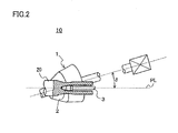
Fig. 2 is a side view of a piercing mill in the process of piercing and rolling; -
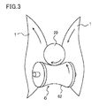
Fig. 3 is a schematic view showing the rotation direction of inclined rolls, a guide roll, and a round billet as viewed from the inlet side of the piercing mill; -
Fig. 4 is a schematic view of a piercing mill according to a second embodiment of the invention as viewed from above; -
Fig. 5 is a front view of the guide roll shown inFig. 4 ; -
Fig. 6 is a schematic view showing the rotation direction of the inclined rolls, the guide roll, and a round billet as viewed from the inlet side of the piercing mill; and -
Fig. 7 is a schematic view of a piercing mill according to a third embodiment of the invention as viewed from above. - Now, embodiments of the invention will be described in detail in conjunction with the accompanying drawings, in which the same or corresponding portions are denoted by the same reference characters and their description is not repeated.
- With reference to
Figs. 1 and2 , a piercingmill 10 includes two cone type inclined rolls (hereinafter simply as "inclined rolls") 1, aplug 2, amandrel 3, apusher 4, aninlet trough 7, an HMD (Hot Metal Detector) 51 provided on the outlet side of the piercingmill 10. - The two
inclined rolls 1 are provided opposed to each other with a pass line PL therebetween. Theinclined rolls 1 have an inclination angle δ and a crossed axes angle γ with respect to the pass line PL. Theplug 2 is provided between the twoinclined rolls 1 and on the pass line PL. Themandrel 3 is provided along the pass line PL on the outlet side of the piercingmill 10 and has its tip end connected to the rear end of theplug 2. - The
pusher 4 is provided in the front of the inlet side of the piercingmill 10 and along the pass line PL. Thepusher 4 includes a cylindermain body 41, acylinder shaft 42, aconnection member 43, and abillet push rod 44. Thebillet push rod 44 is coupled with thecylinder shaft 42 by theconnection member 43 so that it can rotate in the circumferential direction. Theconnection portion 43 includes for example a bearing that allows thebillet push rod 44 to rotate in the circumferential direction. - The cylinder
main body 41 is a hydraulic or electromotive type device and advances/withdraws thecylinder shaft 42. Thepusher 4 has the tip end surface of thebillet push rod 44 abutted against the rear end surface of theround billet 20, and thecylinder shaft 42 and thebillet push rod 44 are advanced by the cylindermain body 41, so that theround billet 20 is pushed forward from behind. - The
pusher 4 advances theround billet 20 forward along the pass line and pushes it in between the twoinclined rolls 1. Thepusher 4 further advances theround billet 20 at least until theround billet 20 advances for a prescribed distance after it contacts the inclined rolls. Stated differently, thepusher 4 pushes theround billet 20 forward with no defective biting until theround billet 20 is stably pierced and rolled. - The
HMD 51 as a detector is provided on the outlet side of the piercingmill 10 and near the rear ends of the inclined rolls 1. TheHMD 51 detects whether the tip end of theround billet 20 pierced and rolled (i.e., hollow shell) has passed between the inclined rolls 1. When theHMD 51 detects the tip end of the pierced and rolledround billet 20, thepusher 4 stops pushing theround billet 20. At theinlet trough 7, around billet 20 yet to be pierced and rolled is placed. Note that the piercingmill 1 includes two guides above and below theplug 2 though not shown inFig. 1 . The guides are for example disk rolls. - The piercing
mill 10 further includes aguide roll 6. Theguide roll 6 is provided between thepusher 4 and the inclined rolls 1.Fig. 3 is a schematic view of theinclined rolls 1, theguide roll 6 and theround billet 20 during piercing and rolling operation when viewed from the inlet side of the piercingmill 10. As shown inFig. 3 , the height of theguide roll 6 is adjusted so that the surface of theround billet 20 pushed by thepusher 4 contacts thesurface 62 of the guide roll. - Referring back to
Fig. 1 , theguide roll 6 includes aroll shaft 61 and theroll surface 62. Theroll shaft 61 is arranged obliquely with respect to the pass line PL. Since theroll shaft 61 is inclined with respect to the pass line PL in this way, theguide roll 6 can provide theround billet 20 with rotation in the circumferential direction. - The
roll surface 62 has an arch section in the direction of theroll shaft 61. Therefore, theround billet 20 passing on theguide roll 6 is not easily shifted in the horizontal direction and from the pass line PL. As compared to the case in which theroll surface 62 is flat, the contact region (contact area) between theroll surface 62 and theround billet 20 is large. Therefore, the force of theguide roll 6 to grip theround billet 20 is large, which allows theround billet 20 to be rotated more easily. - The
guide roll 6 is not coupled to a driving source such as a motor. More specifically, theguide roll 6 is an undriven, free roll. Therefore, theguide roll 6 is rotated by external force received from theround billet 20 when theround billet 20 pushed by thepusher 4 contacts theroll surface 62. In this way, theguide roll 6 rotates by the external force from theround billet 20, and therefore the component of the advancing direction of theround billet 20 in the rotation speed of theguide roll 6 is substantially equal to the advancing speed of theround billet 20. Consequently, theguide roll 6 does not easily run idle and slip on the surface of theround billet 20. As a result, outer surface defects on theround billet 20 attributable to the slipping can be restrained. - As shown in
Fig. 1 , when theinclined rolls 1 are rotated anticlockwise as viewed from the inlet side of the piercingmill 10, theguide roll 6 is provided obliquely with respect to the pass line PL so that theright end 61R of theroll shaft 61 is closer to theplug 2 than theleft end 61L. In this way, as shown inFig. 3 , the rotation direction provided to theround billet 20 by theguide roll 6 matches the rotation direction provided to theround billet 20 by the inclined rolls 1. Therefore, the friction force in the rotation direction (torque) when theround billet 20 contacts theinclined rolls 1 can be restrained. - Note that when the
inclined rolls 1 are rotated clockwise as viewed from the inlet side of the piercingmill 10, theguide roll 6 is provided so that theleft end 61L is closer to theplug 2 than theright end 61R. In short, theguide roll 6 is provided so that the rotation direction provided to theround billet 20 by theguide roll 6 matches the rotation direction provided to theround billet 20 by the inclined rolls 1. - Now, the operation of the piercing
mill 10 during piercing and rolling will be described. - The
round billet 20 is provided on theinlet trough 7. Then, thepusher 4 advances thebillet push rod 44 to have the tip end of thebillet push rod 44 contacted to the rear end of theround billet 20. Then, thepusher 4 advances thebillet push rod 44 and moves theround billet 20 toward the inclined rolls 1. Theround billet 20 advances on theinlet trough 7 as it is pushed by thepusher 4. - When the tip end of the
round billet 20 contacts theroll surface 62 of theguide roll 6, theguide roll 6 starts to rotate following the movement of theround billet 20. At the time, theguide roll 6 is provided obliquely with respect to the pass line PL, and therefore theguide roll 6 provides theround billet 20 with rotation. As a result, theround billet 20 advances as it helically rotates. - The
pusher 4 advances theround billet 20 after theround billet 20 starts to be rotated by theguide roll 6. Therefore, theround billet 20 contacts the surface of theinclined rolls 1 as it rotates. Thepusher 4 pushes theround billet 20 forward for a prescribed distance after theround billet 20 contacts the inclined rolls 1. This is for the purpose of restraining defective biting. - The
round billet 20 rotates in advance in the same direction as the direction of rotation provided by the inclined rolls 1. Therefore, the friction force applied to theinclined rolls 1 is smaller than when theround billet 20 is bitten between theinclined rolls 1 without being rotated. As a result, the wear amount of theinclined rolls 1 is reduced. - When the
HMD 51 provided behind theinclined rolls 1 detects the tip end of the pierced and rolledround billet 20, thepusher 4 stops pushing theround billet 20. This is because when the tip end of theround billet 20 passes the rear ends of the inclined rolls, the piercing and rolling moves from a non-steady state to a steady state, and therefore theround billet 20 is pierced and rolled stably at a constant advancing speed if thepusher 4 does not push theround billet 20. Here, the non-steady state refers to the period between when the tip end of theround billet 20 contacts theinclined rolls 1 and when the tip end of the pierced and rolledround billet 20 passes (departs) the rear end of the inclined rolls 1. The steady state refers to the period after the non-steady state, in other words, the period after the tip end of the pierced and rolledround billet 20 passes the rear ends of theinclined rolls 1 in which theround billet 20 is pierced and rolled at a substantially constant advancing speed. - Note that according to the above-described embodiment, the
pusher 4 continues to push theround billet 20 until the piercing and rolling reaches the steady state, while thepusher 4 may stop pushing theround billet 20 with a different timing. For example, thepusher 4 may stop pushing theround billet 20 in the non-steady state. The effects of invention are obtained as long as thepusher 4 continues to push theround billet 20 at least until theround billet 20 advances for a prescribed distance after it contacts the surfaces of the inclined rolls 1. - According to the above-described embodiment, only one guide roll is provided, while two guide rolls may be provided.
- With reference to
Figs. 4 and5 , a piercingmill 11 according to a second embodiment includes aguide roll 8 in addition to the first embodiment. Theguide roll 8 is provided opposed to theguide roll 6 with the pass line PL therebetween. Theguide roll 8 is supported by achock 81. Theguide roll 8 is elevated/lowered in the vertical direction by an elevator 84 (for example a hydraulic or electromotive cylinder) connected to achock support plate 82. As shown inFig. 4 , theroll shaft 61 of theguide roll 6 and theroll shaft 83 of theguide roll 8 cross each other. Theroll shaft 83 is provided obliquely with respect to the pass line PL. More preferably, when theinclined rolls 1 rotate anticlockwise as viewed from the inlet side of the piercingmill 11, theguide roll 8 is provided obliquely with respect to the pass Line PL so that theleft end 83L of theroll shaft 83 is closer to theplug 2 than theright end 83R. The roll surface of theguide roll 8 has the same shape as that of thesurface 62 of theguide roll 6. More specifically, the roll surface of theguide roll 8 has an arch section in the direction of the roll shaft. Note that inFig. 5 , theroll shafts roll shafts roll shafts - As the
round billet 20 pushed forward by thepusher 4 passes on theguide roll 6, theelevator 84 lowers theguide roll 8. Therefore, theround billet 20 is held between the guide rolls 6 and 8. More specifically, the surface of theround billet 20 contacts the roll surfaces of the guide rolls 6 and 8. Since theroll shafts round billet 20 with rotation in the same direction as shown inFig. 6 . - The
round billet 20 advances as it is held between the guide rolls 6 and 8. Therefore, theround billet 20 is not easily shifted from the pass line PL in the horizontal direction and advances straightforward stably along the pass line PL. Furthermore, the two guide rolls rotate theround billet 20 in the circumferential direction as they hold theround billet 20 between them, and therefore the rotation is stabilized. Theguide roll 8 is not coupled to a driving source similarly to theguide roll 6, in other words, it is an undriven, free roll. Therefore, theguide roll 8 does not easily slip at the surface of theround billet 20. - The elevating/lowering timing of the
guide roll 8 is for example determined by anHMD 52 shown inFig. 4 . TheHMD 52 is provided before the guide rolls 6 and 8. Theelevator 84 lowers the guide roll 8 a prescribed period after the tip end of theround billet 20 passes theHMD 52. In this way, the two guide rolls 6 and 8 can hold theround billet 20 between them. When theHMD 51 detects the tip end of the pierced and rolledround billet 20, theelevator 84 elevates theguide roll 8. This is because the piercing and rolling moves to the steady state. On the other hand, even after the transition to the steady state, the guide rolls 6 and 8 may continue to hold theround billet 20. - With reference to
Fig. 7 , a piercingmill 12 according to a third embodiment includes a plurality of guide rolls 6 in addition to the second embodiment. - The plurality of guide rolls 6 and the
guide roll 8 are arranged zigzag along the pass line PL. More specifically, the guide rolls 6 and guideroll 8 are arranged so that the pass line PL is provided between them. The guide rolls 6 and theguide roll 8 are provided alternately along the pass line PL. The other structure is the same as that shown inFig. 4 . The timing of elevating/lowering theguide roll 8 is the same as that of the second embodiment. - In this case, the
round billet 20 advances as it is held between the guide rolls 6 and 8 as is the case with the second embodiment. Therefore, theround billet 20 is not easily shifted in the horizontal direction from the pass line PL. - Since the guide rolls 6 and 8 are arranged zigzag, the
round billet 20 advances as it is further held by the guide rolls 6 and 8 in three different points in the lengthwise direction. In this way, the front and rear ends of theround billet 20 are less likely to be shifted from the pass line PL in the vertical direction. Therefore, theround billet 20 advances straightforward in an even more stable manner along the pass line PL. - Note that in
Fig. 7 , the piercingmill 12 includes the two guide rolls 6 and the oneguide roll 8, but the piercingmill 12 may include oneguide roll 6 and a plurality of guide rolls 8. Alternatively, there may be a plurality of guide rolls 6 and a plurality of guide rolls 8. - According to the embodiment described above, the roll surfaces of the guide rolls 6 and 8 each have a concave arch shaped section, and the concave arch shape is for example a circular or elliptical shape. The shape may be a curve having a plurality of concave curvatures or may include a straight segment. The roll surfaces of the guide rolls 6 and 8 preferably have geometrically designed shapes to be in contact with the surface of the
round billet 20. - According to the second embodiment, the guide rolls 6 and 8 are provided in the vertical direction with the pass line PL between them but they may be arranged in the horizontal direction.
- According to the embodiment, there are two inclined rolls but there may be three or more inclined rolls. The
inclined roll 1 is a cone type but it may be a barrel type. - Using the piercing mill according to the invention including undriven guide rolls and a piercing mill shown in
Fig. 1 removed of the guide rolls 6 (hereinafter referred to as "comparative piercing mill"), a plurality of round billets were pierced and rolled while they were each pushed by the pusher, after the rolling, the wear amounts of the inclined rolls were measured. - For each of the inventive piercing mill and the comparative piercing mill, the inclination angle δ was 10°, the crossed axes angle γ was 15°, the billet diameter reduction at plug nose was 4%, the roll diameter at the roll gorge portion was 410 mm, and the roll revolution number N was 1 rps. The piercing mills each included two inclined rolls. The inventive piercing mill included two guide rolls according to the second embodiment.
- A round billet of SUS 304 stainless steel according to JIS standards having an outer diameter of 70 mm was heated to 1200°C, and then pierced and rolled by each piercing mill into a hollow shell having an outer diameter of 75 mm and a thickness of 5 mm. The inventive and comparative piercing mills each pierced and rolled a plurality of such round billets. More specifically, the pushing force of the pusher was set to values in
test conditions 1 to 4 in Table 1 and 50 round billets were pierced and rolled in each of the test conditions.Table 1 test condition pushing force
(ton)billet outer diameter
(mm)inclined roll wear amount in comparative piercing mill
(mm)inclined roll wear amount in inventive piercing mill
(mm)1 4 70 0.6 0.3 2 3 70 0.3 0.12 3 2 70 0.2 0.08 4 1 70 0.1 0.04 - After the 50 round billets were pierced and rolled in each of
test conditions 1 to 4, the wear amount at the inclined rolls in each of the piercing mills was measured by the following method. The inclined rolls before piercing operation were each attached to a lathe and marked in eight arbitrary positions in the circumferential direction. Then, the profiles of each sectional shape in the roll shaft direction including each marking position at the roll surface between the inlet side tip end of the inclined roll and the gorge portion were measured using a dial gauge. Then, after the piercing and rolling, each of the inclined rolls was again attached to the lathe and the profiles at the roll surface were measured in the same manner as that carried out before the piercing operation. The profiles before and after the piercing were compared to produce the wear amounts. - The wear amounts of the inclined rolls in each test condition are given in Table 1. With reference to Table 1, in each of
test conditions 1 to 4, the wear amount of the inventive piercing mill was smaller than that of the comparative piercing mill. - Using the inventive piercing mill having the structure shown in
Fig. 7 and the comparative piercing mill described above, a plurality of round billets were pierced and rolled while they were each pushed by the pusher, and after the rolling, the wear amounts of the inclined rolls were measured. - For each of the inventive piercing mill and the comparative piercing mill, the inclination angle δ was 10°, the crossed axes angle γ was 15°, the billet diameter reduction at plug nose was 3.1%, the roll diameter at the roll gorge portion was 410 mm, and the roll revolution number N was 1 rps.
- A round billet of alloy steel containing 13 mass % Cr (13% Cr steel) and having an outer diameter of 70 mm was prepared. The prepared round billet was heated to 1200°C, and then pierced and rolled by each piercing mill into a hollow shell having an outer diameter of 75 mm and a thickness of 5 mm. The inventive and comparative piercing mills each pierced and rolled a plurality of such round billets. More specifically, the pushing force of the pusher was set to values in test conditions 5 to 8 in Table 2 and 60 round billets were pierced and rolled in each of the test conditions.
Table 2 test condition pushing force
(ton)billet outer diameter
(mm)inclined roll wear amount in comparative piercing mill
(mm)inclined roll wear amount in inventive piercing mill
(mm)5 4.2 70 0.62 0.36 6 3.1 70 0.30 0.15 7 2.5 70 0.23 0.11 8 1.5 70 0.15 0.06 - After 60 round billets were pierced and rolled in each of test conditions 5 to 8, the inclined rolls of the piercing mills were measured for their wear amounts. The wear amounts were measured in the same manner as that of Example 1.
- The wear amounts of the inclined rolls in each of the test conditions are given in Table 2. With reference to Table 2, in any of test conditions 5 to 8, the wear amount of the inventive piercing mill was smaller than that of the comparative piercing mill.
- Although the embodiment of the present invention has been described, the same is by way of illustration and example only and is not to be taken by way of limitation. The invention may be embodied in various modified forms without departing from the spirit and scope of the invention.
- The piercing mill according to the invention is applicable for wide use in the field of piercing and rolling metal pipes or tubes.
Claims (3)
- A piercing mill piercing and rolling a round billet into a hollow shell, comprising:a plurality of inclined rolls provided around a pass line;a pusher provided in front of said inclined rolls to push said round billet from the rear end at least until said round billet advances for a prescribed distance after contacting said inclined rolls; andan undriven first guide roll provided between said inclined rolls and said pusher and including a first roll shaft arranged obliquely with respect to said pass line and a first roll surface having a concave arch sectional shape in the direction of said first roll shaft.
- The piercing mill according to claim 1, further comprising an undriven second guide roll provided opposed to said first guide roll with said pass line therebetween and including a second roll shaft crossing said first roll shaft and a second roll surface having a concave arch sectional shape in the direction of said second roll shaft.
- The piercing mill according to claim 2, comprising a plurality of said first guide rolls, wherein said plurality of first guide rolls and said second guide roll are arranged zigzag along said pass line.
Applications Claiming Priority (2)
| Application Number | Priority Date | Filing Date | Title |
|---|---|---|---|
| JP2007090644 | 2007-03-30 | ||
| PCT/JP2008/050277 WO2008126427A1 (en) | 2007-03-30 | 2008-01-11 | Boring machine |
Publications (3)
| Publication Number | Publication Date |
|---|---|
| EP2130621A1 true EP2130621A1 (en) | 2009-12-09 |
| EP2130621A4 EP2130621A4 (en) | 2013-06-26 |
| EP2130621B1 EP2130621B1 (en) | 2014-06-11 |
Family
ID=39863586
Family Applications (1)
| Application Number | Title | Priority Date | Filing Date |
|---|---|---|---|
| EP08703141.5A Active EP2130621B1 (en) | 2007-03-30 | 2008-01-11 | Boring machine |
Country Status (8)
| Country | Link |
|---|---|
| US (1) | US8104316B2 (en) |
| EP (1) | EP2130621B1 (en) |
| JP (1) | JP5071476B2 (en) |
| CN (1) | CN101652196B (en) |
| AR (1) | AR067287A1 (en) |
| BR (1) | BRPI0809609B1 (en) |
| MX (1) | MX2009010607A (en) |
| WO (1) | WO2008126427A1 (en) |
Families Citing this family (8)
| Publication number | Priority date | Publication date | Assignee | Title |
|---|---|---|---|---|
| JP4826949B2 (en) * | 2006-09-11 | 2011-11-30 | 住友金属工業株式会社 | Seamless pipe manufacturing status monitoring apparatus and method, and seamless pipe manufacturing equipment |
| JP5334325B2 (en) * | 2010-04-16 | 2013-11-06 | ユニクラフトナグラ株式会社 | Deep hole forming apparatus and method for hollow parts |
| CN103394526A (en) * | 2013-08-01 | 2013-11-20 | 安吉县鹏大钢管有限公司 | Efficient, energy-saving and environment-friendly round steel piercing device |
| JP6102854B2 (en) * | 2014-07-29 | 2017-03-29 | Jfeスチール株式会社 | Pusher drive device and drive method for applying back pressure to billet |
| CN104588411A (en) * | 2015-01-26 | 2015-05-06 | 张家港兴业钢管有限公司 | Perforating machine for producing seamless steel tube |
| CN108393783A (en) * | 2018-04-24 | 2018-08-14 | 北京瀚川鑫冶工程技术有限公司 | A kind of belt bar, wire rod, tubing grinding-polishing process equipment and its production line |
| CN111069298B (en) * | 2019-12-19 | 2021-10-08 | 太原重工股份有限公司 | Digital control system and method for puncher |
| US12172202B2 (en) * | 2020-04-30 | 2024-12-24 | Jfe Steel Corporation | Skew rolling apparatus, method for manufacturing seamless pipe shell, and method for manufacturing seamless steel pipe |
Family Cites Families (24)
| Publication number | Priority date | Publication date | Assignee | Title |
|---|---|---|---|---|
| US401143A (en) * | 1889-04-09 | flagler | ||
| US636335A (en) * | 1897-12-28 | 1899-11-07 | John Arthur Hampton | Seamless-tube-rolling mill. |
| US1219802A (en) * | 1916-05-12 | 1917-03-20 | Harrison M Brightman | Process of forming a tube. |
| US1882655A (en) * | 1928-09-27 | 1932-10-18 | Walter R Clark | Machine for rolling or piercing billets |
| US1999987A (en) * | 1933-05-24 | 1935-04-30 | Diescher Tube Mills Inc | Cross-roll |
| US2309690A (en) * | 1940-08-21 | 1943-02-02 | Andrew J Aiken | Apparatus for producing seamless tubes |
| US2306827A (en) * | 1940-10-24 | 1942-12-29 | William T Mohan | Apparatus for making metallic pipes and tubes |
| US3550415A (en) * | 1969-01-13 | 1970-12-29 | United States Steel Corp | Feed and toe angle indicator for billet-piercing mill |
| US4006618A (en) * | 1974-07-23 | 1977-02-08 | Samon Yanagimoto | Method of producing seamless steel tube |
| US4318294A (en) * | 1978-12-29 | 1982-03-09 | Nippon Steel Corporation | Method of manufacturing seamless metal pipes and tubes |
| DE3432288C2 (en) * | 1984-09-01 | 1987-01-02 | Kocks Technik Gmbh & Co, 4010 Hilden | Use of inert gas in the manufacture of seamless pipes |
| IT1185129B (en) * | 1985-06-28 | 1987-11-04 | Innocenti Santeustacchio Spa | METHOD AND EQUIPMENT FOR DRIVING A BILLET AT THE ENTRANCE TO A ROLLER-PERFORATOR |
| DE3602176C1 (en) * | 1986-01-23 | 1987-08-13 | Mannesmann Ag | Cross roll mill |
| US4798071A (en) * | 1986-06-25 | 1989-01-17 | Kocks Technik Gmbh & Co. | Seamless tube production |
| JPS63174704A (en) * | 1987-01-13 | 1988-07-19 | Sumitomo Heavy Ind Ltd | Guide shoe of roll piercer |
| JPS63220907A (en) * | 1987-03-09 | 1988-09-14 | Sumitomo Metal Ind Ltd | Piercing rolling method by rolling mill with inclined roll |
| JP2633858B2 (en) | 1987-07-10 | 1997-07-23 | 株式会社日立製作所 | Probe microscope |
| JPS6415601U (en) * | 1987-07-17 | 1989-01-26 | ||
| JPH079013A (en) * | 1993-06-29 | 1995-01-13 | Nkk Corp | Seamless steel pipe manufacturing equipment |
| CN2216438Y (en) * | 1994-12-23 | 1996-01-03 | 冶金工业部钢铁研究总院 | Conical roll core rod compound extender |
| JPH0910806A (en) * | 1995-04-26 | 1997-01-14 | Nippon Steel Corp | Tilt rolling device and tilt rolling method for seamless steel pipe |
| JP2000246311A (en) | 1999-03-03 | 2000-09-12 | Nkk Corp | Seamless pipe manufacturing method for difficult-to-process materials or as cast round slabs |
| JP3425718B2 (en) * | 1999-12-06 | 2003-07-14 | Jfeエンジニアリング株式会社 | Seamless pipe manufacturing method |
| JP2006297400A (en) | 2005-04-15 | 2006-11-02 | Sanyo Special Steel Co Ltd | Drilling method for seamless steel pipe |
-
2008
- 2008-01-11 MX MX2009010607A patent/MX2009010607A/en active IP Right Grant
- 2008-01-11 EP EP08703141.5A patent/EP2130621B1/en active Active
- 2008-01-11 JP JP2009508928A patent/JP5071476B2/en active Active
- 2008-01-11 CN CN2008800110644A patent/CN101652196B/en active Active
- 2008-01-11 BR BRPI0809609A patent/BRPI0809609B1/en active IP Right Grant
- 2008-01-11 WO PCT/JP2008/050277 patent/WO2008126427A1/en not_active Ceased
- 2008-03-28 AR ARP080101294A patent/AR067287A1/en active IP Right Grant
-
2009
- 2009-09-29 US US12/568,698 patent/US8104316B2/en active Active
Also Published As
| Publication number | Publication date |
|---|---|
| JPWO2008126427A1 (en) | 2010-07-22 |
| BRPI0809609A2 (en) | 2014-10-29 |
| US20100011831A1 (en) | 2010-01-21 |
| BRPI0809609B1 (en) | 2020-04-07 |
| US8104316B2 (en) | 2012-01-31 |
| WO2008126427A1 (en) | 2008-10-23 |
| AR067287A1 (en) | 2009-10-07 |
| EP2130621B1 (en) | 2014-06-11 |
| CN101652196B (en) | 2013-02-06 |
| CN101652196A (en) | 2010-02-17 |
| MX2009010607A (en) | 2009-10-22 |
| EP2130621A4 (en) | 2013-06-26 |
| JP5071476B2 (en) | 2012-11-14 |
Similar Documents
| Publication | Publication Date | Title |
|---|---|---|
| US8104316B2 (en) | Piercing mill | |
| EP2002904B1 (en) | Method of manufacturing seamless pipe | |
| CN101410196A (en) | Process for manufacturing a seamless tube | |
| US10232418B2 (en) | Method for producing seamless metal pipe | |
| EP2754508B1 (en) | Seamless-metal-pipe manufacturing method | |
| US7146836B2 (en) | Piercing method for manufacturing of seamless pipe | |
| US7739892B2 (en) | Method of manufacturing seamless pipes | |
| US10894278B2 (en) | Method for producing seamless metal tube | |
| EP2168696B1 (en) | Seamless pipe manufacturing method using pusher device for piercing-rolling | |
| JP3082678B2 (en) | Manufacturing method of small diameter seamless metal pipe | |
| EP1649945B1 (en) | Drilling/rolling method in manufacturing seamless tube | |
| EP4108352A1 (en) | Inclined rolling equipment, method for producing seamless tube blank, and method for producing seamless steel tube | |
| US20130255342A1 (en) | Method for producing seamless tube/pipe | |
| JP3820896B2 (en) | Seamless pipe inclined rolling mill and rolling method thereof | |
| JP4563133B2 (en) | Manufacturing method of low residual stress seamless steel pipe for cutting rings with excellent straightness and roundness | |
| JP3785916B2 (en) | Rolling method for seamless metal pipe | |
| JP2003305515A (en) | Shape steel straightening device | |
| JPH05177221A (en) | Pipe tilt rolling method | |
| JPS63174704A (en) | Guide shoe of roll piercer | |
| JPH09248605A (en) | Method and apparatus for piercing and rolling seamless metal pipe | |
| JPH07164022A (en) | Tilt rolling mill for seamless pipe manufacturing | |
| JPS5976602A (en) | Production of seamless pipe |
Legal Events
| Date | Code | Title | Description |
|---|---|---|---|
| PUAI | Public reference made under article 153(3) epc to a published international application that has entered the european phase |
Free format text: ORIGINAL CODE: 0009012 |
|
| 17P | Request for examination filed |
Effective date: 20090908 |
|
| AK | Designated contracting states |
Kind code of ref document: A1 Designated state(s): AT BE BG CH CY CZ DE DK EE ES FI FR GB GR HR HU IE IS IT LI LT LU LV MC MT NL NO PL PT RO SE SI SK TR |
|
| DAX | Request for extension of the european patent (deleted) | ||
| RAP1 | Party data changed (applicant data changed or rights of an application transferred) |
Owner name: NIPPON STEEL & SUMITOMO METAL CORPORATION |
|
| A4 | Supplementary search report drawn up and despatched |
Effective date: 20130528 |
|
| RIC1 | Information provided on ipc code assigned before grant |
Ipc: B21B 19/04 20060101AFI20130522BHEP Ipc: B21B 39/14 20060101ALI20130522BHEP |
|
| GRAP | Despatch of communication of intention to grant a patent |
Free format text: ORIGINAL CODE: EPIDOSNIGR1 |
|
| INTG | Intention to grant announced |
Effective date: 20140116 |
|
| GRAS | Grant fee paid |
Free format text: ORIGINAL CODE: EPIDOSNIGR3 |
|
| GRAA | (expected) grant |
Free format text: ORIGINAL CODE: 0009210 |
|
| AK | Designated contracting states |
Kind code of ref document: B1 Designated state(s): AT BE BG CH CY CZ DE DK EE ES FI FR GB GR HR HU IE IS IT LI LT LU LV MC MT NL NO PL PT RO SE SI SK TR |
|
| REG | Reference to a national code |
Ref country code: GB Ref legal event code: FG4D |
|
| REG | Reference to a national code |
Ref country code: CH Ref legal event code: EP |
|
| REG | Reference to a national code |
Ref country code: IE Ref legal event code: FG4D |
|
| REG | Reference to a national code |
Ref country code: AT Ref legal event code: REF Ref document number: 671986 Country of ref document: AT Kind code of ref document: T Effective date: 20140715 |
|
| REG | Reference to a national code |
Ref country code: DE Ref legal event code: R096 Ref document number: 602008032688 Country of ref document: DE Effective date: 20140724 |
|
| PG25 | Lapsed in a contracting state [announced via postgrant information from national office to epo] |
Ref country code: LT Free format text: LAPSE BECAUSE OF FAILURE TO SUBMIT A TRANSLATION OF THE DESCRIPTION OR TO PAY THE FEE WITHIN THE PRESCRIBED TIME-LIMIT Effective date: 20140611 Ref country code: GR Free format text: LAPSE BECAUSE OF FAILURE TO SUBMIT A TRANSLATION OF THE DESCRIPTION OR TO PAY THE FEE WITHIN THE PRESCRIBED TIME-LIMIT Effective date: 20140912 Ref country code: FI Free format text: LAPSE BECAUSE OF FAILURE TO SUBMIT A TRANSLATION OF THE DESCRIPTION OR TO PAY THE FEE WITHIN THE PRESCRIBED TIME-LIMIT Effective date: 20140611 Ref country code: NO Free format text: LAPSE BECAUSE OF FAILURE TO SUBMIT A TRANSLATION OF THE DESCRIPTION OR TO PAY THE FEE WITHIN THE PRESCRIBED TIME-LIMIT Effective date: 20140911 |
|
| REG | Reference to a national code |
Ref country code: NL Ref legal event code: VDEP Effective date: 20140611 |
|
| REG | Reference to a national code |
Ref country code: AT Ref legal event code: MK05 Ref document number: 671986 Country of ref document: AT Kind code of ref document: T Effective date: 20140611 |
|
| REG | Reference to a national code |
Ref country code: LT Ref legal event code: MG4D |
|
| PG25 | Lapsed in a contracting state [announced via postgrant information from national office to epo] |
Ref country code: LV Free format text: LAPSE BECAUSE OF FAILURE TO SUBMIT A TRANSLATION OF THE DESCRIPTION OR TO PAY THE FEE WITHIN THE PRESCRIBED TIME-LIMIT Effective date: 20140611 Ref country code: SE Free format text: LAPSE BECAUSE OF FAILURE TO SUBMIT A TRANSLATION OF THE DESCRIPTION OR TO PAY THE FEE WITHIN THE PRESCRIBED TIME-LIMIT Effective date: 20140611 Ref country code: HR Free format text: LAPSE BECAUSE OF FAILURE TO SUBMIT A TRANSLATION OF THE DESCRIPTION OR TO PAY THE FEE WITHIN THE PRESCRIBED TIME-LIMIT Effective date: 20140611 |
|
| PG25 | Lapsed in a contracting state [announced via postgrant information from national office to epo] |
Ref country code: SK Free format text: LAPSE BECAUSE OF FAILURE TO SUBMIT A TRANSLATION OF THE DESCRIPTION OR TO PAY THE FEE WITHIN THE PRESCRIBED TIME-LIMIT Effective date: 20140611 Ref country code: EE Free format text: LAPSE BECAUSE OF FAILURE TO SUBMIT A TRANSLATION OF THE DESCRIPTION OR TO PAY THE FEE WITHIN THE PRESCRIBED TIME-LIMIT Effective date: 20140611 Ref country code: ES Free format text: LAPSE BECAUSE OF FAILURE TO SUBMIT A TRANSLATION OF THE DESCRIPTION OR TO PAY THE FEE WITHIN THE PRESCRIBED TIME-LIMIT Effective date: 20140611 Ref country code: CZ Free format text: LAPSE BECAUSE OF FAILURE TO SUBMIT A TRANSLATION OF THE DESCRIPTION OR TO PAY THE FEE WITHIN THE PRESCRIBED TIME-LIMIT Effective date: 20140611 Ref country code: RO Free format text: LAPSE BECAUSE OF FAILURE TO SUBMIT A TRANSLATION OF THE DESCRIPTION OR TO PAY THE FEE WITHIN THE PRESCRIBED TIME-LIMIT Effective date: 20140611 Ref country code: PT Free format text: LAPSE BECAUSE OF FAILURE TO SUBMIT A TRANSLATION OF THE DESCRIPTION OR TO PAY THE FEE WITHIN THE PRESCRIBED TIME-LIMIT Effective date: 20141013 |
|
| PG25 | Lapsed in a contracting state [announced via postgrant information from national office to epo] |
Ref country code: NL Free format text: LAPSE BECAUSE OF FAILURE TO SUBMIT A TRANSLATION OF THE DESCRIPTION OR TO PAY THE FEE WITHIN THE PRESCRIBED TIME-LIMIT Effective date: 20140611 Ref country code: IS Free format text: LAPSE BECAUSE OF FAILURE TO SUBMIT A TRANSLATION OF THE DESCRIPTION OR TO PAY THE FEE WITHIN THE PRESCRIBED TIME-LIMIT Effective date: 20141011 Ref country code: PL Free format text: LAPSE BECAUSE OF FAILURE TO SUBMIT A TRANSLATION OF THE DESCRIPTION OR TO PAY THE FEE WITHIN THE PRESCRIBED TIME-LIMIT Effective date: 20140611 Ref country code: AT Free format text: LAPSE BECAUSE OF FAILURE TO SUBMIT A TRANSLATION OF THE DESCRIPTION OR TO PAY THE FEE WITHIN THE PRESCRIBED TIME-LIMIT Effective date: 20140611 |
|
| REG | Reference to a national code |
Ref country code: DE Ref legal event code: R097 Ref document number: 602008032688 Country of ref document: DE |
|
| PLBE | No opposition filed within time limit |
Free format text: ORIGINAL CODE: 0009261 |
|
| STAA | Information on the status of an ep patent application or granted ep patent |
Free format text: STATUS: NO OPPOSITION FILED WITHIN TIME LIMIT |
|
| PG25 | Lapsed in a contracting state [announced via postgrant information from national office to epo] |
Ref country code: DK Free format text: LAPSE BECAUSE OF FAILURE TO SUBMIT A TRANSLATION OF THE DESCRIPTION OR TO PAY THE FEE WITHIN THE PRESCRIBED TIME-LIMIT Effective date: 20140611 |
|
| 26N | No opposition filed |
Effective date: 20150312 |
|
| REG | Reference to a national code |
Ref country code: DE Ref legal event code: R097 Ref document number: 602008032688 Country of ref document: DE Effective date: 20150312 |
|
| PG25 | Lapsed in a contracting state [announced via postgrant information from national office to epo] |
Ref country code: BE Free format text: LAPSE BECAUSE OF FAILURE TO SUBMIT A TRANSLATION OF THE DESCRIPTION OR TO PAY THE FEE WITHIN THE PRESCRIBED TIME-LIMIT Effective date: 20140611 |
|
| PG25 | Lapsed in a contracting state [announced via postgrant information from national office to epo] |
Ref country code: SI Free format text: LAPSE BECAUSE OF FAILURE TO SUBMIT A TRANSLATION OF THE DESCRIPTION OR TO PAY THE FEE WITHIN THE PRESCRIBED TIME-LIMIT Effective date: 20140611 |
|
| REG | Reference to a national code |
Ref country code: CH Ref legal event code: PL |
|
| PG25 | Lapsed in a contracting state [announced via postgrant information from national office to epo] |
Ref country code: LU Free format text: LAPSE BECAUSE OF FAILURE TO SUBMIT A TRANSLATION OF THE DESCRIPTION OR TO PAY THE FEE WITHIN THE PRESCRIBED TIME-LIMIT Effective date: 20150111 |
|
| GBPC | Gb: european patent ceased through non-payment of renewal fee |
Effective date: 20150111 |
|
| PG25 | Lapsed in a contracting state [announced via postgrant information from national office to epo] |
Ref country code: MC Free format text: LAPSE BECAUSE OF FAILURE TO SUBMIT A TRANSLATION OF THE DESCRIPTION OR TO PAY THE FEE WITHIN THE PRESCRIBED TIME-LIMIT Effective date: 20140611 |
|
| PG25 | Lapsed in a contracting state [announced via postgrant information from national office to epo] |
Ref country code: CH Free format text: LAPSE BECAUSE OF NON-PAYMENT OF DUE FEES Effective date: 20150131 Ref country code: LI Free format text: LAPSE BECAUSE OF NON-PAYMENT OF DUE FEES Effective date: 20150131 Ref country code: GB Free format text: LAPSE BECAUSE OF NON-PAYMENT OF DUE FEES Effective date: 20150111 |
|
| REG | Reference to a national code |
Ref country code: IE Ref legal event code: MM4A |
|
| REG | Reference to a national code |
Ref country code: FR Ref legal event code: PLFP Year of fee payment: 9 |
|
| PG25 | Lapsed in a contracting state [announced via postgrant information from national office to epo] |
Ref country code: IE Free format text: LAPSE BECAUSE OF NON-PAYMENT OF DUE FEES Effective date: 20150111 |
|
| REG | Reference to a national code |
Ref country code: FR Ref legal event code: PLFP Year of fee payment: 10 |
|
| PG25 | Lapsed in a contracting state [announced via postgrant information from national office to epo] |
Ref country code: MT Free format text: LAPSE BECAUSE OF FAILURE TO SUBMIT A TRANSLATION OF THE DESCRIPTION OR TO PAY THE FEE WITHIN THE PRESCRIBED TIME-LIMIT Effective date: 20140611 |
|
| PG25 | Lapsed in a contracting state [announced via postgrant information from national office to epo] |
Ref country code: HU Free format text: LAPSE BECAUSE OF FAILURE TO SUBMIT A TRANSLATION OF THE DESCRIPTION OR TO PAY THE FEE WITHIN THE PRESCRIBED TIME-LIMIT; INVALID AB INITIO Effective date: 20080111 Ref country code: BG Free format text: LAPSE BECAUSE OF FAILURE TO SUBMIT A TRANSLATION OF THE DESCRIPTION OR TO PAY THE FEE WITHIN THE PRESCRIBED TIME-LIMIT Effective date: 20140611 |
|
| PG25 | Lapsed in a contracting state [announced via postgrant information from national office to epo] |
Ref country code: CY Free format text: LAPSE BECAUSE OF FAILURE TO SUBMIT A TRANSLATION OF THE DESCRIPTION OR TO PAY THE FEE WITHIN THE PRESCRIBED TIME-LIMIT Effective date: 20140611 |
|
| PG25 | Lapsed in a contracting state [announced via postgrant information from national office to epo] |
Ref country code: TR Free format text: LAPSE BECAUSE OF FAILURE TO SUBMIT A TRANSLATION OF THE DESCRIPTION OR TO PAY THE FEE WITHIN THE PRESCRIBED TIME-LIMIT Effective date: 20140611 |
|
| REG | Reference to a national code |
Ref country code: FR Ref legal event code: PLFP Year of fee payment: 11 |
|
| REG | Reference to a national code |
Ref country code: DE Ref legal event code: R082 Ref document number: 602008032688 Country of ref document: DE Representative=s name: DOMPATENT VON KREISLER SELTING WERNER - PARTNE, DE Ref country code: DE Ref legal event code: R081 Ref document number: 602008032688 Country of ref document: DE Owner name: NIPPON STEEL CORPORATION, JP Free format text: FORMER OWNER: NIPPON STEEL & SUMITOMO METAL CORP., TOKYO, JP |
|
| PGFP | Annual fee paid to national office [announced via postgrant information from national office to epo] |
Ref country code: FR Payment date: 20251128 Year of fee payment: 19 |
|
| PGFP | Annual fee paid to national office [announced via postgrant information from national office to epo] |
Ref country code: DE Payment date: 20251203 Year of fee payment: 19 |
|
| PGFP | Annual fee paid to national office [announced via postgrant information from national office to epo] |
Ref country code: IT Payment date: 20251219 Year of fee payment: 19 |