EP2130578A1 - Exhaust gas purification apparatus - Google Patents
Exhaust gas purification apparatus Download PDFInfo
- Publication number
- EP2130578A1 EP2130578A1 EP08738920A EP08738920A EP2130578A1 EP 2130578 A1 EP2130578 A1 EP 2130578A1 EP 08738920 A EP08738920 A EP 08738920A EP 08738920 A EP08738920 A EP 08738920A EP 2130578 A1 EP2130578 A1 EP 2130578A1
- Authority
- EP
- European Patent Office
- Prior art keywords
- adsorbing device
- moisture
- exhaust
- zeolite
- gas
- Prior art date
- Legal status (The legal status is an assumption and is not a legal conclusion. Google has not performed a legal analysis and makes no representation as to the accuracy of the status listed.)
- Granted
Links
Images


Classifications
-
- F—MECHANICAL ENGINEERING; LIGHTING; HEATING; WEAPONS; BLASTING
- F01—MACHINES OR ENGINES IN GENERAL; ENGINE PLANTS IN GENERAL; STEAM ENGINES
- F01N—GAS-FLOW SILENCERS OR EXHAUST APPARATUS FOR MACHINES OR ENGINES IN GENERAL; GAS-FLOW SILENCERS OR EXHAUST APPARATUS FOR INTERNAL-COMBUSTION ENGINES
- F01N3/00—Exhaust or silencing apparatus having means for purifying, rendering innocuous, or otherwise treating exhaust
- F01N3/08—Exhaust or silencing apparatus having means for purifying, rendering innocuous, or otherwise treating exhaust for rendering innocuous
- F01N3/0807—Exhaust or silencing apparatus having means for purifying, rendering innocuous, or otherwise treating exhaust for rendering innocuous by using absorbents or adsorbents
-
- B—PERFORMING OPERATIONS; TRANSPORTING
- B01—PHYSICAL OR CHEMICAL PROCESSES OR APPARATUS IN GENERAL
- B01D—SEPARATION
- B01D53/00—Separation of gases or vapours; Recovering vapours of volatile solvents from gases; Chemical or biological purification of waste gases, e.g. engine exhaust gases, smoke, fumes, flue gases, aerosols
- B01D53/26—Drying gases or vapours
- B01D53/28—Selection of materials for use as drying agents
-
- B—PERFORMING OPERATIONS; TRANSPORTING
- B01—PHYSICAL OR CHEMICAL PROCESSES OR APPARATUS IN GENERAL
- B01D—SEPARATION
- B01D53/00—Separation of gases or vapours; Recovering vapours of volatile solvents from gases; Chemical or biological purification of waste gases, e.g. engine exhaust gases, smoke, fumes, flue gases, aerosols
- B01D53/02—Separation of gases or vapours; Recovering vapours of volatile solvents from gases; Chemical or biological purification of waste gases, e.g. engine exhaust gases, smoke, fumes, flue gases, aerosols by adsorption, e.g. preparative gas chromatography
-
- B—PERFORMING OPERATIONS; TRANSPORTING
- B01—PHYSICAL OR CHEMICAL PROCESSES OR APPARATUS IN GENERAL
- B01D—SEPARATION
- B01D53/00—Separation of gases or vapours; Recovering vapours of volatile solvents from gases; Chemical or biological purification of waste gases, e.g. engine exhaust gases, smoke, fumes, flue gases, aerosols
- B01D53/26—Drying gases or vapours
- B01D53/261—Drying gases or vapours by adsorption
-
- B—PERFORMING OPERATIONS; TRANSPORTING
- B01—PHYSICAL OR CHEMICAL PROCESSES OR APPARATUS IN GENERAL
- B01D—SEPARATION
- B01D53/00—Separation of gases or vapours; Recovering vapours of volatile solvents from gases; Chemical or biological purification of waste gases, e.g. engine exhaust gases, smoke, fumes, flue gases, aerosols
- B01D53/34—Chemical or biological purification of waste gases
-
- B—PERFORMING OPERATIONS; TRANSPORTING
- B01—PHYSICAL OR CHEMICAL PROCESSES OR APPARATUS IN GENERAL
- B01D—SEPARATION
- B01D53/00—Separation of gases or vapours; Recovering vapours of volatile solvents from gases; Chemical or biological purification of waste gases, e.g. engine exhaust gases, smoke, fumes, flue gases, aerosols
- B01D53/34—Chemical or biological purification of waste gases
- B01D53/46—Removing components of defined structure
- B01D53/54—Nitrogen compounds
- B01D53/56—Nitrogen oxides
-
- B—PERFORMING OPERATIONS; TRANSPORTING
- B01—PHYSICAL OR CHEMICAL PROCESSES OR APPARATUS IN GENERAL
- B01D—SEPARATION
- B01D53/00—Separation of gases or vapours; Recovering vapours of volatile solvents from gases; Chemical or biological purification of waste gases, e.g. engine exhaust gases, smoke, fumes, flue gases, aerosols
- B01D53/34—Chemical or biological purification of waste gases
- B01D53/74—General processes for purification of waste gases; Apparatus or devices specially adapted therefor
- B01D53/81—Solid phase processes
-
- B—PERFORMING OPERATIONS; TRANSPORTING
- B01—PHYSICAL OR CHEMICAL PROCESSES OR APPARATUS IN GENERAL
- B01D—SEPARATION
- B01D53/00—Separation of gases or vapours; Recovering vapours of volatile solvents from gases; Chemical or biological purification of waste gases, e.g. engine exhaust gases, smoke, fumes, flue gases, aerosols
- B01D53/34—Chemical or biological purification of waste gases
- B01D53/92—Chemical or biological purification of waste gases of engine exhaust gases
- B01D53/94—Chemical or biological purification of waste gases of engine exhaust gases by catalytic processes
- B01D53/9481—Catalyst preceded by an adsorption device without catalytic function for temporary storage of contaminants, e.g. during cold start
-
- B—PERFORMING OPERATIONS; TRANSPORTING
- B01—PHYSICAL OR CHEMICAL PROCESSES OR APPARATUS IN GENERAL
- B01J—CHEMICAL OR PHYSICAL PROCESSES, e.g. CATALYSIS OR COLLOID CHEMISTRY; THEIR RELEVANT APPARATUS
- B01J20/00—Solid sorbent compositions or filter aid compositions; Sorbents for chromatography; Processes for preparing, regenerating or reactivating thereof
- B01J20/02—Solid sorbent compositions or filter aid compositions; Sorbents for chromatography; Processes for preparing, regenerating or reactivating thereof comprising inorganic material
- B01J20/10—Solid sorbent compositions or filter aid compositions; Sorbents for chromatography; Processes for preparing, regenerating or reactivating thereof comprising inorganic material comprising silica or silicate
- B01J20/16—Alumino-silicates
- B01J20/18—Synthetic zeolitic molecular sieves
- B01J20/186—Chemical treatments in view of modifying the properties of the sieve, e.g. increasing the stability or the activity, also decreasing the activity
-
- F—MECHANICAL ENGINEERING; LIGHTING; HEATING; WEAPONS; BLASTING
- F01—MACHINES OR ENGINES IN GENERAL; ENGINE PLANTS IN GENERAL; STEAM ENGINES
- F01N—GAS-FLOW SILENCERS OR EXHAUST APPARATUS FOR MACHINES OR ENGINES IN GENERAL; GAS-FLOW SILENCERS OR EXHAUST APPARATUS FOR INTERNAL-COMBUSTION ENGINES
- F01N13/00—Exhaust or silencing apparatus characterised by constructional features
- F01N13/009—Exhaust or silencing apparatus characterised by constructional features having two or more separate purifying devices arranged in series
-
- B—PERFORMING OPERATIONS; TRANSPORTING
- B01—PHYSICAL OR CHEMICAL PROCESSES OR APPARATUS IN GENERAL
- B01D—SEPARATION
- B01D2253/00—Adsorbents used in seperation treatment of gases and vapours
- B01D2253/10—Inorganic adsorbents
- B01D2253/106—Silica or silicates
- B01D2253/108—Zeolites
-
- B—PERFORMING OPERATIONS; TRANSPORTING
- B01—PHYSICAL OR CHEMICAL PROCESSES OR APPARATUS IN GENERAL
- B01D—SEPARATION
- B01D2255/00—Catalysts
- B01D2255/20—Metals or compounds thereof
- B01D2255/207—Transition metals
- B01D2255/20738—Iron
-
- B—PERFORMING OPERATIONS; TRANSPORTING
- B01—PHYSICAL OR CHEMICAL PROCESSES OR APPARATUS IN GENERAL
- B01D—SEPARATION
- B01D2255/00—Catalysts
- B01D2255/50—Zeolites
-
- B—PERFORMING OPERATIONS; TRANSPORTING
- B01—PHYSICAL OR CHEMICAL PROCESSES OR APPARATUS IN GENERAL
- B01D—SEPARATION
- B01D2255/00—Catalysts
- B01D2255/90—Physical characteristics of catalysts
- B01D2255/91—NOx-storage component incorporated in the catalyst
-
- B—PERFORMING OPERATIONS; TRANSPORTING
- B01—PHYSICAL OR CHEMICAL PROCESSES OR APPARATUS IN GENERAL
- B01D—SEPARATION
- B01D2258/00—Sources of waste gases
- B01D2258/01—Engine exhaust gases
- B01D2258/012—Diesel engines and lean burn gasoline engines
-
- F—MECHANICAL ENGINEERING; LIGHTING; HEATING; WEAPONS; BLASTING
- F01—MACHINES OR ENGINES IN GENERAL; ENGINE PLANTS IN GENERAL; STEAM ENGINES
- F01N—GAS-FLOW SILENCERS OR EXHAUST APPARATUS FOR MACHINES OR ENGINES IN GENERAL; GAS-FLOW SILENCERS OR EXHAUST APPARATUS FOR INTERNAL-COMBUSTION ENGINES
- F01N2570/00—Exhaust treating apparatus eliminating, absorbing or adsorbing specific elements or compounds
- F01N2570/14—Nitrogen oxides
-
- F—MECHANICAL ENGINEERING; LIGHTING; HEATING; WEAPONS; BLASTING
- F01—MACHINES OR ENGINES IN GENERAL; ENGINE PLANTS IN GENERAL; STEAM ENGINES
- F01N—GAS-FLOW SILENCERS OR EXHAUST APPARATUS FOR MACHINES OR ENGINES IN GENERAL; GAS-FLOW SILENCERS OR EXHAUST APPARATUS FOR INTERNAL-COMBUSTION ENGINES
- F01N2570/00—Exhaust treating apparatus eliminating, absorbing or adsorbing specific elements or compounds
- F01N2570/22—Water or humidity
-
- Y—GENERAL TAGGING OF NEW TECHNOLOGICAL DEVELOPMENTS; GENERAL TAGGING OF CROSS-SECTIONAL TECHNOLOGIES SPANNING OVER SEVERAL SECTIONS OF THE IPC; TECHNICAL SUBJECTS COVERED BY FORMER USPC CROSS-REFERENCE ART COLLECTIONS [XRACs] AND DIGESTS
- Y02—TECHNOLOGIES OR APPLICATIONS FOR MITIGATION OR ADAPTATION AGAINST CLIMATE CHANGE
- Y02A—TECHNOLOGIES FOR ADAPTATION TO CLIMATE CHANGE
- Y02A50/00—TECHNOLOGIES FOR ADAPTATION TO CLIMATE CHANGE in human health protection, e.g. against extreme weather
- Y02A50/20—Air quality improvement or preservation, e.g. vehicle emission control or emission reduction by using catalytic converters
-
- Y—GENERAL TAGGING OF NEW TECHNOLOGICAL DEVELOPMENTS; GENERAL TAGGING OF CROSS-SECTIONAL TECHNOLOGIES SPANNING OVER SEVERAL SECTIONS OF THE IPC; TECHNICAL SUBJECTS COVERED BY FORMER USPC CROSS-REFERENCE ART COLLECTIONS [XRACs] AND DIGESTS
- Y02—TECHNOLOGIES OR APPLICATIONS FOR MITIGATION OR ADAPTATION AGAINST CLIMATE CHANGE
- Y02T—CLIMATE CHANGE MITIGATION TECHNOLOGIES RELATED TO TRANSPORTATION
- Y02T10/00—Road transport of goods or passengers
- Y02T10/10—Internal combustion engine [ICE] based vehicles
- Y02T10/12—Improving ICE efficiencies
Definitions
- the present invention relates to an exhaust-gas converting apparatus that can suppress the emission of NO x in low-temperature region at the time of starting.
- catalysts for converting exhaust gas By means of the strengthening of automotive exhaust-gas regulations, the developments of catalysts for converting exhaust gas have advanced, and thereby the emission amounts of HC, CO and NO x in exhaust gases have been becoming extremely less recently.
- these catalysts for converting exhaust gas the following are representative ones: three-way catalysts that are used at air-fuel ratios that are controlled in the vicinity of stoichiometry; and NO x storage-and-reduction catalysts that are used in atmospheres that are turned into rich atmosphere during lean atmosphere intermittently.
- these catalysts for converting exhaust gas are those in which Pt, Rh and the like are adapted into the active metals, the catalytic activities are not generally expressed until they reach the activation temperatures of 200 °C or more, and they are associated with such a problem that the harmful components have been emitted without ever being converted in low-temperature region such as at the time of starting.
- an adsorption material such as zeolite
- zeolite is put in place on an upstream side of a catalyst for converting exhaust gas
- the harmful components are captured onto the adsorption material in low-temperature region
- the harmful components are eliminated from the adsorption material after the catalyst for purifying exhaust gas has undergone temperature rise to the activation temperature or more, and then they are converted with a downstream-side catalyst for converting exhaust gas.
- a catalyst for converting exhaust gas in which a front-stage catalyst with Rh being supported on a zeolite is put in place on an exhaust-gas upstream side, and a rear-stage catalyst with Pt or Pd being supported is put in place on a downstream side thereof.
- NO x adsorb onto the front-stage catalyst in low-temperature region, and NO x , which have been eliminated from the front-stage catalyst in high-temperature region, are then converted by means of reduction at the rear-stage catalyst.
- the moisture content in exhaust gases that flow into the low-temperature NO x adsorption material is controlled to 0.4%-2.4% approximately by means of the moisture trap; and accordingly NO x adsorption amount of the low-temperature NO x adsorption material augments; and thereby it is possible to reduce the release of unconverted NO x considerably at the time of low temperatures.
- NO x adsorption materials comprising zeolites in which transition metal ions are supported by means of ion exchange adsorb NO x in an extremely great amount in low-temperature region; however, it became apparent that, in such NO x adsorption materials, the less the moisture content in exhaust gas that flows in is the more the NO x adsorption amount augments.
- the present invention is one which has been done in view of the aforementioned circumstances, and it is an assignment to be solved to make an exhaust-gas converting apparatus that can adsorb a great amount of NO x in low-temperature region by using an NO x adsorption material comprising a zeolite that includes a transition metal ion and then selecting a moisture adsorption material that is optimum for it.
- the moisture adsorbing device can include at least one of an alkali metal ion and an alkaline-earth metal ion in the cation exchange sites.
- the transition metal ion that is included in the NO x adsorbing device can be an iron ion.
- a moisture adsorbing device, and an NO x adsorbing device are put in place from the upstream side of exhaust gas toward the downstream side in this order.
- the moisture adsorbing device comprises a type Y zeolite.
- Moisture (H 2 O) is adsorbed onto the Al-positions of the zeolite; but it is feasible to synthesize the type Y zeolite even when an SiO 2 /Al 2 O 3 molar ratio is 15 or less; and the Al 2 O 3 proportion is great; and the adsorption amount of moisture is great, compared with the other zeolites.
- the hydrothermal resistance lowers in zeolites whose Al 2 O 3 proportion is too much, the SiO 2 /Al 2 O 3 molar ratio of the type Y zeolite being used herein is 5 or more, and the hydrothermal resistance is also satisfied.
- the moisture adsorption amount at the moisture adsorbing device is great, and accordingly it is possible to make moisture in the exhaust gases that flow into the NO x adsorbing device zero virtually.
- a great amount of NO x can be adsorbed at the NO x adsorbing device, and thereby it is possible to securely prevent the emission of NO x in low-temperature region.
- the moisture adsorbing performance, and the hydrothermal resistance improves furthermore.
- the transition metal ion that is included in the NO x adsorbing device is adapted into an iron ion, since the less the moisture content in exhaust gas is the more especially the NO x adsorbing capability improves, the NO x adsorbing capability in low-temperature region improves furthermore by means of the combination with the moisture adsorbing device that comprises the type Y zeolite.
- the moisture adsorbing deice comprises the type Y zeolite.
- type A zeolites, type X zeolites, and type Y zeolites have been known.
- zeolites excepting type Y zeolites are associated with a drawback in view of the hydrothermal resistance as specified in Table 1, and accordingly it is difficult to use them for exhaust-gas conversion.
- type Y zeolites As for the type Y zeolites, the following have been known: H-Y type ones in which H + exists in the cation exchange sites; Na-Y type ones in which Na + exists in the cation exchange sites, and the like. Although it is possible to use any one of them, it is preferable to use a type Y zeolite that includes at least one of an alkali metal ion and alkaline-earth metal ion in the cation exchange sites. By doing thusly, the hydrothermal resistance improves furthermore as specified in Table 1.
- the moisture adsorbing device although it is possible to use one which is made by molding the type Y zeolite into a pelletized shape and then filling it up in a container, it is desirable to make it into a honeycomb configuration in order to prevent the enlargement of pressure loss.
- a honeycomb body of a ceramic powder that includes the type Y zeolite there might arise such a case that the resulting strength becomes deficient.
- a monolithic substrate which comprises cordierite or the like that has been used widely as a substrate of catalyst for converting exhaust gas, and then form a coating layer, which comprises the type Y zeolite, onto cellular partition-wall surfaces thereof.
- the NO x adsorbing device comprises the zeolite that includes a transition metal ion in the cation exchange sites.
- zeolite that is used for the NO x adsorbing device ZSM-5, mordenite, and zeolite beta are recommended.
- zeolite beta ZSM-5, mordenite, and zeolite beta are recommended.
- Y zeolite or ferrierite the ion exchange of the transition metal ion becomes difficult, and accordingly the resulting NO x adsorbing capability has become low considerably.
- it is a type A zeolite or type X zeolite, it is associated with a problem in view of the hydrothermal resistance as described above.
- the zeolite that is used for the NO x adsorbing device those whose SiO 2 /Al 2 O 3 molar ratio is 200 or less is desirable. Since the cation exchange sites exist sufficiently by means of this, it is possible to have it include the transition metal ion sufficiently.
- the transition metal although it is possible to use Fe, Co and the like, Fe is especially desirable.
- Fe ferric chloride
- the NO x adsorbing device although it is possible to use one which is made by molding the zeolite including the transition metal ion into a pelletized shape and then filling it up in a container, it is desirable to make it into a honeycomb configuration, in the same manner as the moisture adsorbing device, in order to prevent the enlargement of pressure loss.
- a honeycomb body of a ceramic powder that includes the zeolite including the transition metal ion there might arise such a case that the resulting strength becomes deficient.
- a monolithic substrate which comprises cordierite or the like that has been used widely as a substrate of catalyst for converting exhaust gas, and then form a coating layer, which comprises the zeolite that includes the transition metal ion, onto cellular partition-wall surfaces thereof.
- a bypass flow passage independently of a usual main exhaust-gas flow passage and then put the exhaust-gas converting apparatus according to the present invention in place in the bypass flow passage.
- exhaust gases are low temperatures, such as 200 °C or less, for instance, it is desirable to let the exhaust gases distribute through the bypass flow passage only in order to suppress the emission of NO x by adsorbing NO x onto the NO x adsorbing device; whereas, in high-temperature range, it is desirable to flow exhaust gases through the main exhaust-gas flow passage, and additionally to connect the bypass passage to an EGR, thereby returning NO x , which have been released from the exhaust-gas converting apparatus according to the present invention, to an engine.
- FIG. 1 an exhaust-gas converting apparatus according to the present example is illustrated.
- This exhaust-gas converting apparatus comprises a moisture adsorbing device 1 that is disposed in an exhaust-gas flow passage, and an NO x adsorbing device 2 that is put in place on an exhaust-gas downstream side thereof.
- the moisture adsorbing device 1 comprises a honeycomb substrate 10 that is made of cordierite, and a coating layer 11 that is formed on cellular partition-wall surfaces thereof; and the coating layer 11 is constituted of a type Na-Y zeolite.
- the NO x adsorbing device 2 comprises a honeycomb substrate 20 that is made of cordierite, and a coating layer 21 that is formed on cellular partition-wall surfaces thereof; and the coating layer 21 is constituted of ZSM-5 that has been underwent ion exchange with Fe.
- ZSM-5 whose SiO 2 /Al 2 O 3 molar ratio was 28 was made ready, and was then impregnated with a predetermined amount of an aqueous solution in which FeCl 3 was dissolved. This was held at 400 °C for 2 hours in an electric furnace, and then ion exchange was carried out so that Fe and Al made such amounts as 1:1 by atomic ratio, thereby preparing an Fe/ZSM-5 powder. Subsequently, the Fe/ZSM-5 powder was mixed with an SiO 2 -system binder and pure water to prepare a slurry. This slurry was wash coated onto a 35-c.c. honeycomb substrate 20 that was made of cordierite, was dried and then calcined to form a 6.3-g coating layer 21, and was labeled an NO x adsorbing device 2.
- Example No. 1 The same NO x adsorbing device 2 as that of Example No. 1 was put in place on an exhaust-gas flow upstream side, the same moisture adsorbing device 1 as that of Example No. 1 was then put in place on an exhaust-gas flow downstream side of the NO x adsorbing device 2, and was labeled an exhaust-gas converting apparatus according to Comparative Example No. 1.
- Example No. 1 With respect to each of the exhaust-gas converting apparatuses according to Example No. 1 and Comparative Example No. 1, a model gas given in Table 2 was distributed at a temperature of 50 °C in a flow volume of 10 L/min. for 20 seconds, and then HC adsorption rates and NO adsorption rates were measured from the differences between inlet gas concentrations and outlet gas concentrations. The results are given in Table 3.
- Example No. 1 Only the same NO x adsorbing device 2 as that of Example No. 1 was used, and H 2 O was first adsorbed onto it fully. Thereafter, it was heated at three levels, namely, at 160 °C, 230 °C and 350 °C, for 2 hours, respectively, thereby eliminating (or purging) the adsorbed H 2 O. The higher the heating temperature was the less the remaining H 2 O was. Thereafter, a mixture gas comprising NO and N 2 was distributed immediately to measure the adsorption rates of NO. The results are illustrated in Fig. 3 .
- a coating layer that comprised a type A zeolite was formed in an amount of 160 g onto a honeycomb substrate (900 c.c.) that was made of cordierite, there by preparing a moisture adsorbing device. Upon mounting this moisture adsorbing device into an exhaust system of actual engine and then measuring the H 2 O emission amount at the time of LA#4 travelling continuously, the emission of H 2 O was suppressed completely for a time period of about 20 seconds since the time of starting. This means that the entire amount of H 2 O, which was emitted during that period, was absorbed onto the coating layer.
- a first HC adsorbing device 4 that comprised a mixture of ZSM-5 and a type Y zeolite, and a second HC adsorbing device 5 that had been completed by subjecting ferrierite to ion exchange with Ag were put in place on an exhaust-gas downstream side of the moisture adsorbing device 3 that had been prepared in Testing Example No. 2, as illustrated in Fig. 4 ; and the same NO x adsorbing device 2 as that of Example No. 1 was put in place on a furthermore downstream side of them.
- the NO x emission amount at the time of LA#4 travelling was measured continuously from the time of starting.
- Example No. 1 a coating layer that comprised a type Na-Y zeolite was formed in an amount of 160 g onto a honeycomb substrate (900 c.c.) that was made of cordierite, thereby preparing a moisture adsorbing device 3. Moreover, except that a 900-c.c. honeycomb substrate 20 that was made of cordierite was used, an NO x adsorbing device 2 that possessed the 160-g coating layer 21 was prepared in the same manner as Example No. 1.
- Example No. 2 Except that no moisture adsorbing device 3 was put in place, the NO x adsorption rate was measured in the same manner as Example No. 2. The results are given in Table 4.
- Example No. 2 From Table 4, whereas the NO x adsorption rate fluctuated in comparative Example No. 2, the NO x adsorption rate of 94% or more was always secured in Example No. 2. It is believed that this was caused by the presence or absence of the moisture adsorbing device 3, and that the fluctuation of the NO x adsorption rate in Comparative Example No. 2 resulted from the influence of moisture in the exhaust gases. It is apparent that, in Example No. 2, namely, in the counterpart, the high NO x adsorption rate could be secured because the exhaust gases, which did not include any moisture due to the moisture adsorbing device 3, flowed into the NO x adsorbing device 3.
- the exhaust-gas converting apparatus it is possible for the exhaust-gas converting apparatus according to the present invention to suppress the emission of NO x greatly in low-temperature region, such as at the time of starting, by putting it in place on an exhaust-gas upstream side of a catalyst for converting exhaust gas, such as three-way catalysts and NO x storage-and-reduction catalysts.
- a catalyst for converting exhaust gas such as three-way catalysts and NO x storage-and-reduction catalysts.
Landscapes
- Chemical & Material Sciences (AREA)
- Engineering & Computer Science (AREA)
- Chemical Kinetics & Catalysis (AREA)
- Analytical Chemistry (AREA)
- General Chemical & Material Sciences (AREA)
- Oil, Petroleum & Natural Gas (AREA)
- Environmental & Geological Engineering (AREA)
- Combustion & Propulsion (AREA)
- Biomedical Technology (AREA)
- Health & Medical Sciences (AREA)
- General Engineering & Computer Science (AREA)
- Mechanical Engineering (AREA)
- Inorganic Chemistry (AREA)
- Organic Chemistry (AREA)
- Materials Engineering (AREA)
- Exhaust Gas After Treatment (AREA)
- Solid-Sorbent Or Filter-Aiding Compositions (AREA)
- Treating Waste Gases (AREA)
- Drying Of Gases (AREA)
Abstract
Description
- The present invention relates to an exhaust-gas converting apparatus that can suppress the emission of NOx in low-temperature region at the time of starting.
- By means of the strengthening of automotive exhaust-gas regulations, the developments of catalysts for converting exhaust gas have advanced, and thereby the emission amounts of HC, CO and NOx in exhaust gases have been becoming extremely less recently. As for these catalysts for converting exhaust gas, the following are representative ones: three-way catalysts that are used at air-fuel ratios that are controlled in the vicinity of stoichiometry; and NOx storage-and-reduction catalysts that are used in atmospheres that are turned into rich atmosphere during lean atmosphere intermittently.
- However, since these catalysts for converting exhaust gas are those in which Pt, Rh and the like are adapted into the active metals, the catalytic activities are not generally expressed until they reach the activation temperatures of 200 °C or more, and they are associated with such a problem that the harmful components have been emitted without ever being converted in low-temperature region such as at the time of starting.
- Hence, the following have been carried out: an adsorption material, such as zeolite, is put in place on an upstream side of a catalyst for converting exhaust gas; the harmful components are captured onto the adsorption material in low-temperature region; and the harmful components are eliminated from the adsorption material after the catalyst for purifying exhaust gas has undergone temperature rise to the activation temperature or more, and then they are converted with a downstream-side catalyst for converting exhaust gas.
- For example, in Japanese Unexamined Patent Publication (KOKAI) Gazette No.
2000-312,827 - However, in low-temperature NOx adsorption materials that utilize zeolites, such as the front-stage catalyst as set forth in the aforementioned gazette, there have been such a phenomenon that, due to the influence of moisture that is included in exhaust gases, the NOx adsorption amount lowers. Hence, in Japanese Patent Publication Gazette No.
3,636,116 - According to the studies by the present-application inventors, it became apparent that the lowering degree of NOx adsorption amount by means of moisture differs depending on the types of NOx adsorption material. And, it was found that NOx adsorption materials comprising zeolites in which transition metal ions are supported by means of ion exchange adsorb NOx in an extremely great amount in low-temperature region; however, it became apparent that, in such NOx adsorption materials, the less the moisture content in exhaust gas that flows in is the more the NOx adsorption amount augments.
- In Japanese Patent Publication Gazette No.
3,636,116 - The present invention is one which has been done in view of the aforementioned circumstances, and it is an assignment to be solved to make an exhaust-gas converting apparatus that can adsorb a great amount of NOx in low-temperature region by using an NOx adsorption material comprising a zeolite that includes a transition metal ion and then selecting a moisture adsorption material that is optimum for it.
- A characteristic of an exhaust-gas converting apparatus according to the present invention which solves the aforementioned assignment lies in that it includes:
- a moisture adsorbing device comprising a type Y zeolite; and
- an NOx adsorbing device being put in place on an exhaust-gas downstream side of the moisture adsorbing device, and comprising a zeolite that includes a transition metal ion in the cation exchange sites.
- It is desirable that the moisture adsorbing device can include at least one of an alkali metal ion and an alkaline-earth metal ion in the cation exchange sites. Moreover, it is desirable that the transition metal ion that is included in the NOx adsorbing device can be an iron ion.
-
-
Fig. 1 is a schematic diagram for illustrating a construction of an exhaust-gas converting apparatus according to the present invention; -
Fig. 2 is an explanatory diagram for illustrating a presumed state of a cation exchange site in an NOx adsorbing device that was used in the present invention; -
Fig. 3 is a graph for illustrating a relationship between remaining moisture contents and NO adsorption rates in the NOx adsorbing device; -
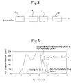
Fig. 4 is a schematic explanatory diagram of an exhaust-gas converting apparatus that was used in Testing Example No. 3, Example No. 2 and Comparative Example No. 2; and -
Fig. 5 illustrates results in Testing Example No. 3, and is a graph for illustrating the changes of NOx emission amount with time since the time of starting. - In an exhaust-gas converting apparatus according to the present invention, a moisture adsorbing device, and an NOx adsorbing device are put in place from the upstream side of exhaust gas toward the downstream side in this order. The moisture adsorbing device comprises a type Y zeolite. Moisture (H2O) is adsorbed onto the Al-positions of the zeolite; but it is feasible to synthesize the type Y zeolite even when an SiO2/Al2O3 molar ratio is 15 or less; and the Al2O3 proportion is great; and the adsorption amount of moisture is great, compared with the other zeolites. Moreover, although the hydrothermal resistance lowers in zeolites whose Al2O3 proportion is too much, the SiO2/Al2O3 molar ratio of the type Y zeolite being used herein is 5 or more, and the hydrothermal resistance is also satisfied.
- Moreover, in the NOx adsorbing device comprising a zeolite that includes a transition metal ion in the cation exchange sites, the less the moisture amount in exhaust gas is the more the NOx adsorbing capability improves.
- Therefore, when exhaust gases are in low-temperature region, the moisture adsorption amount at the moisture adsorbing device is great, and accordingly it is possible to make moisture in the exhaust gases that flow into the NOx adsorbing device zero virtually. By means of this, a great amount of NOx can be adsorbed at the NOx adsorbing device, and thereby it is possible to securely prevent the emission of NOx in low-temperature region.
- And, when using a type Y zeolite that includes at least one of an alkali metal ion and an alkaline-earth metal ion in the cation exchange sites for the moisture adsorbing device, the moisture adsorbing performance, and the hydrothermal resistance improves furthermore.
- Moreover, when the transition metal ion that is included in the NOx adsorbing device is adapted into an iron ion, since the less the moisture content in exhaust gas is the more especially the NOx adsorbing capability improves, the NOx adsorbing capability in low-temperature region improves furthermore by means of the combination with the moisture adsorbing device that comprises the type Y zeolite.
- The moisture adsorbing deice comprises the type Y zeolite. As for so-called hydrophilic zeolite, type A zeolites, type X zeolites, and type Y zeolites have been known. However, zeolites excepting type Y zeolites are associated with a drawback in view of the hydrothermal resistance as specified in Table 1, and accordingly it is difficult to use them for exhaust-gas conversion.
- As for the type Y zeolites, the following have been known: H-Y type ones in which H+ exists in the cation exchange sites; Na-Y type ones in which Na+ exists in the cation exchange sites, and the like. Although it is possible to use any one of them, it is preferable to use a type Y zeolite that includes at least one of an alkali metal ion and alkaline-earth metal ion in the cation exchange sites. By doing thusly, the hydrothermal resistance improves furthermore as specified in Table 1. Moreover, in the H-Y type ones whose cation exchange sites are vacant, there might arise a case where the crystals are unstable thermally, and a case where HC in exhaust gas undergo caulking due to the presence of H+ and thereby the enclosure of pores occurs. Note that, as the respective zeolites being used in Table 1, those whose SiO2/Al2O3 molar ratio is 10 or less are selected.
-
TABLE 1 Zeolite Species H2O Adsorbability Hydrothermal Resistance HC Adsorbability Caulking Resistance Type A ⊚ × Δ - Type X ⊚ × ○ - Type H-Y ○ Δ-○ ⊚ × Type Na-Y ○ ○ ⊚ ○ - As the moisture adsorbing device, although it is possible to use one which is made by molding the type Y zeolite into a pelletized shape and then filling it up in a container, it is desirable to make it into a honeycomb configuration in order to prevent the enlargement of pressure loss. In this case, although it is allowable to form a honeycomb body of a ceramic powder that includes the type Y zeolite, there might arise such a case that the resulting strength becomes deficient. Hence, it is desirable to use a monolithic substrate, which comprises cordierite or the like that has been used widely as a substrate of catalyst for converting exhaust gas, and then form a coating layer, which comprises the type Y zeolite, onto cellular partition-wall surfaces thereof.
- The NOx adsorbing device comprises the zeolite that includes a transition metal ion in the cation exchange sites. As for the zeolite that is used for the NOx adsorbing device, ZSM-5, mordenite, and zeolite beta are recommended. When it is a type Y zeolite or ferrierite, the ion exchange of the transition metal ion becomes difficult, and accordingly the resulting NOx adsorbing capability has become low considerably. Moreover, when it is a type A zeolite or type X zeolite, it is associated with a problem in view of the hydrothermal resistance as described above.
- Moreover, the zeolite that is used for the NOx adsorbing device, those whose SiO2/Al2O3 molar ratio is 200 or less is desirable. Since the cation exchange sites exist sufficiently by means of this, it is possible to have it include the transition metal ion sufficiently.
- As for the transition metal, although it is possible to use Fe, Co and the like, Fe is especially desirable. In the case of subjecting Fe to ion exchange, it is preferable to use ferric chloride (FeCl3) as a starting material. Since ferric chloride (FeCl3) sublimes at 300 °C or more, it can enter the micro-fine vacant holes inside zeolite, and accordingly it undergoes ion exchange to almost all of the cation exchange sites. Note that, since it is possible to have it include Fe ions with respect to Al in 1:1 by the number of their atoms, it is believed that Fe is included in such a form as illustrated in
Fig. 2 . - As the NOx adsorbing device, although it is possible to use one which is made by molding the zeolite including the transition metal ion into a pelletized shape and then filling it up in a container, it is desirable to make it into a honeycomb configuration, in the same manner as the moisture adsorbing device, in order to prevent the enlargement of pressure loss. In this case, although it is allowable to form a honeycomb body of a ceramic powder that includes the zeolite including the transition metal ion, there might arise such a case that the resulting strength becomes deficient. Hence, it is desirable to use a monolithic substrate, which comprises cordierite or the like that has been used widely as a substrate of catalyst for converting exhaust gas, and then form a coating layer, which comprises the zeolite that includes the transition metal ion, onto cellular partition-wall surfaces thereof.
- It is possible to put the exhaust-gas converting apparatus according to the present invention on an exhaust-gas upstream of a catalyst for converting exhaust gas, such as a three-way catalyst, for instance, in order to use. However, in a case where the NOx adsorption amount of the NOx adsorbing device is great, NOx that have been eliminated in high-temperature region cannot be reduced fully with the downstream side catalyst for converting exhaust gas, and accordingly there arises such a drawback that an excessive proportion of NOx has been emitted in an instance like that.
- Hence, it is desirable to form a bypass flow passage independently of a usual main exhaust-gas flow passage and then put the exhaust-gas converting apparatus according to the present invention in place in the bypass flow passage. And, when exhaust gases are low temperatures, such as 200 °C or less, for instance, it is desirable to let the exhaust gases distribute through the bypass flow passage only in order to suppress the emission of NOx by adsorbing NOx onto the NOx adsorbing device; whereas, in high-temperature range, it is desirable to flow exhaust gases through the main exhaust-gas flow passage, and additionally to connect the bypass passage to an EGR, thereby returning NOx, which have been released from the exhaust-gas converting apparatus according to the present invention, to an engine.
- Note that it is feasible for HC with relatively high boiling points to adsorb onto the type Y zeolite of the moisture adsorbing device. Therefore, when one which can adsorb HC with low boiling points, such ZSM-5, is used for the zeolite of the NOx adsorbing device, it is possible to successfully adsorb HC in exhaust gases, from those with high boiling points to those with low boiling points, in low-temperature region. Therefore, by putting the exhaust-gas converting apparatus according to the present invention in place in the bypass flow passage as aforementioned, it is possible to suppress the emission of HC and NOx by adsorbing them in low-temperature region; whereas it is possible to react both of them to convert them upon returning them to the engine at the time of high temperatures.
- Hereinafter, the present invention will be explained in detail by means of examples, comparative examples, and testing examples.
- In
Fig. 1 , an exhaust-gas converting apparatus according to the present example is illustrated. This exhaust-gas converting apparatus comprises amoisture adsorbing device 1 that is disposed in an exhaust-gas flow passage, and an NOx adsorbing device 2 that is put in place on an exhaust-gas downstream side thereof. Themoisture adsorbing device 1 comprises ahoneycomb substrate 10 that is made of cordierite, and acoating layer 11 that is formed on cellular partition-wall surfaces thereof; and thecoating layer 11 is constituted of a type Na-Y zeolite. Moreover, the NOx adsorbing device 2 comprises ahoneycomb substrate 20 that is made of cordierite, and acoating layer 21 that is formed on cellular partition-wall surfaces thereof; and thecoating layer 21 is constituted of ZSM-5 that has been underwent ion exchange with Fe. - First of all, a type Na-Y zeolite whose SiO2/Al2O3 molar ratio was 5. 6 was made ready, and was then mixed with an SiO2-system binder and pure water to prepare a slurry. This slurry was wash coated onto a 35-c.c.
honeycomb substrate 10 that was made of cordierite, was dried and then calcined to form a 6.3-g coating layer 11, and was labeled amoisture adsorbing device 1. - Whereas, ZSM-5 whose SiO2/Al2O3 molar ratio was 28 was made ready, and was then impregnated with a predetermined amount of an aqueous solution in which FeCl3 was dissolved. This was held at 400 °C for 2 hours in an electric furnace, and then ion exchange was carried out so that Fe and Al made such amounts as 1:1 by atomic ratio, thereby preparing an Fe/ZSM-5 powder. Subsequently, the Fe/ZSM-5 powder was mixed with an SiO2-system binder and pure water to prepare a slurry. This slurry was wash coated onto a 35-c.c.
honeycomb substrate 20 that was made of cordierite, was dried and then calcined to form a 6.3-g coating layer 21, and was labeled an NOx adsorbing device 2. - The same NOx adsorbing device 2 as that of Example No. 1 was put in place on an exhaust-gas flow upstream side, the same
moisture adsorbing device 1 as that of Example No. 1 was then put in place on an exhaust-gas flow downstream side of the NOx adsorbing device 2, and was labeled an exhaust-gas converting apparatus according to Comparative Example No. 1. - With respect to each of the exhaust-gas converting apparatuses according to Example No. 1 and Comparative Example No. 1, a model gas given in Table 2 was distributed at a temperature of 50 °C in a flow volume of 10 L/min. for 20 seconds, and then HC adsorption rates and NO adsorption rates were measured from the differences between inlet gas concentrations and outlet gas concentrations. The results are given in Table 3.
-
TABLE 2 C3H6 C6H5CH3 NO CO H2O N2 (ppmC) (ppmC) (ppm) (ppm) (%) 1500 1500 900 6000 3 Balance -
TABLE 3 Adsorption Rate (%) Upstream Side Downstream Side HC NO Ex. No. 1 Moisture Adsorbing Device NOx Adsorbing Device 100 100 Comp. Ex. No. 1 NOx Adsorbing Device Moisture Adsorbing Device 100 86 - From Table 3, in accordance with the exhaust-gas converting apparatus according to Example No. 1, both of HC and NO were adsorbed 100%. On the contrary, in the exhaust-gas converting apparatus according to Comparative Example No. 1, although the HC adsorption rate was 100%, the NO adsorption is lower than that of Example No. 1. Although a major cause of this is that moisture was included in the exhaust gas that flowed into the NOx adsorbing device 2, it is believed the following was one of the causes, namely, the adsorption of NO was hindered because of C6H5CH3 being adsorbed onto the NOx adsorbing device 2.
- Only the same NOx adsorbing device 2 as that of Example No. 1 was used, and H2O was first adsorbed onto it fully. Thereafter, it was heated at three levels, namely, at 160 °C, 230 °C and 350 °C, for 2 hours, respectively, thereby eliminating (or purging) the adsorbed H2O. The higher the heating temperature was the less the remaining H2O was. Thereafter, a mixture gas comprising NO and N2 was distributed immediately to measure the adsorption rates of NO. The results are illustrated in
Fig. 3 . - From
Fig. 3 , it is understood that the higher the purging temperature is, that is, the less the adsorption amount of H2O is, the higher the NO adsorption rate is. - A coating layer that comprised a type A zeolite was formed in an amount of 160 g onto a honeycomb substrate (900 c.c.) that was made of cordierite, there by preparing a moisture adsorbing device. Upon mounting this moisture adsorbing device into an exhaust system of actual engine and then measuring the H2O emission amount at the time of LA#4 travelling continuously, the emission of H2O was suppressed completely for a time period of about 20 seconds since the time of starting. This means that the entire amount of H2O, which was emitted during that period, was absorbed onto the coating layer.
- (In the exhaust system of actual engine set forth in Testing Example No. 2, a first HC adsorbing device 4 that comprised a mixture of ZSM-5 and a type Y zeolite, and a second
HC adsorbing device 5 that had been completed by subjecting ferrierite to ion exchange with Ag were put in place on an exhaust-gas downstream side of themoisture adsorbing device 3 that had been prepared in Testing Example No. 2, as illustrated inFig. 4 ; and the same NOx adsorbing device 2 as that of Example No. 1 was put in place on a furthermore downstream side of them. And, the NOx emission amount at the time of LA#4 travelling was measured continuously from the time of starting. Note that, regarding the following cases as well: a case of excepting themoisture adsorbing device 3 and another case of excepting both of themoisture adsorbing device 3 and NOx adsorbingdevice 2; the NOx emission amounts were measured similarly; and the results are illustrated inFig. 5 . - From
Fig. 5 , it is possible to suppress the emission of NOx almost completely by putting themoisture adsorbing device 3 in place on an upstream side of the NOx adsorbing device 2. Specifically, it is apparent that it is possible to adsorb NOx almost completely by letting exhaust gases from which moisture has been removed flow into the NOx adsorbing device 2. Note that, although it was possible to suppress the NOx emission amount to a certain extent even in the case of excepting themoisture adsorbing device 3, this is believed to arise because moisture adsorbed onto the first HC adsorbing device 4 and secondHC adsorbing device 5 to a certain extent. - Note that, in the case of putting both of the
moisture adsorbing device 3 and NOx adsorbingdevice 2 in place, it was possible to secure the 0.3% NOx emission amount on average as a whole during the mode at the time of LA#4 travelling. - In the same manner as Example No. 1, a coating layer that comprised a type Na-Y zeolite was formed in an amount of 160 g onto a honeycomb substrate (900 c.c.) that was made of cordierite, thereby preparing a
moisture adsorbing device 3. Moreover, except that a 900-c.c.honeycomb substrate 20 that was made of cordierite was used, an NOx adsorbing device 2 that possessed the 160-g coating layer 21 was prepared in the same manner as Example No. 1. - These
moisture adsorbing device 3 and NOx adsorbingdevice 2 were put in place into an exhaust system of actual engine along with the HC adsorbing device 4 in the same manner as Testing Example No. 3, and then the NOx emission amount was measured all through during the entire mode at the time of LA#4 travelling to compute the NOx adsorption rate. The results are given in Table 4. - Except that no
moisture adsorbing device 3 was put in place, the NOx adsorption rate was measured in the same manner as Example No. 2. The results are given in Table 4. -
TABLE 4 Upstream Side Downstream Side NOx Adsorption Rate (%) Ex. No. 2 Moisture Adsorbing Device NOx Adsorbing Device 94% or more Comp. Ex. No. 2 - NOx Adsorbing Device 0-90% - From Table 4, whereas the NOx adsorption rate fluctuated in comparative Example No. 2, the NOx adsorption rate of 94% or more was always secured in Example No. 2. It is believed that this was caused by the presence or absence of the
moisture adsorbing device 3, and that the fluctuation of the NOx adsorption rate in Comparative Example No. 2 resulted from the influence of moisture in the exhaust gases. It is apparent that, in Example No. 2, namely, in the counterpart, the high NOx adsorption rate could be secured because the exhaust gases, which did not include any moisture due to themoisture adsorbing device 3, flowed into the NOx adsorbing device 3. - It is possible for the exhaust-gas converting apparatus according to the present invention to suppress the emission of NOx greatly in low-temperature region, such as at the time of starting, by putting it in place on an exhaust-gas upstream side of a catalyst for converting exhaust gas, such as three-way catalysts and NOx storage-and-reduction catalysts.
Claims (3)
- An exhaust-gas adsorbing apparatus being characterized in that it includes:a moisture adsorbing device comprising a type Y zeolite; andan NOx adsorbing device being put in place on an exhaust-gas downstream side of the moisture adsorbing device, and comprising a zeolite that includes a transition metal ion in the cation exchange sites.
- The exhaust-gas converting apparatus as set forth in claim 1, wherein said moisture adsorbing device includes at least one of an alkali metal ion and an alkaline-earth metal ion in the cation exchange sites.
- The exhaust-gas converting apparatus as set forth in claim 1, wherein the transition metal ion that is included in said NOx adsorbing device is an iron ion.
Applications Claiming Priority (2)
| Application Number | Priority Date | Filing Date | Title |
|---|---|---|---|
| JP2007079710A JP5141063B2 (en) | 2007-03-26 | 2007-03-26 | Exhaust gas purification device |
| PCT/JP2008/055732 WO2008117829A1 (en) | 2007-03-26 | 2008-03-26 | Exhaust gas purification apparatus |
Publications (3)
| Publication Number | Publication Date |
|---|---|
| EP2130578A1 true EP2130578A1 (en) | 2009-12-09 |
| EP2130578A4 EP2130578A4 (en) | 2011-04-06 |
| EP2130578B1 EP2130578B1 (en) | 2013-10-30 |
Family
ID=39788562
Family Applications (1)
| Application Number | Title | Priority Date | Filing Date |
|---|---|---|---|
| EP08738920.1A Not-in-force EP2130578B1 (en) | 2007-03-26 | 2008-03-26 | Exhaust gas adsorbing apparatus |
Country Status (6)
| Country | Link |
|---|---|
| US (1) | US8257471B2 (en) |
| EP (1) | EP2130578B1 (en) |
| JP (1) | JP5141063B2 (en) |
| KR (1) | KR101233524B1 (en) |
| CN (1) | CN101641144B (en) |
| WO (1) | WO2008117829A1 (en) |
Cited By (3)
| Publication number | Priority date | Publication date | Assignee | Title |
|---|---|---|---|---|
| EP2873819A1 (en) * | 2013-11-13 | 2015-05-20 | MAN Truck & Bus AG | Exhaust gas after-treatment apparatus and method of heating up the apparatus |
| RU179464U1 (en) * | 2015-11-06 | 2018-05-15 | Атлас Копко Эрпауэр, Намлозе Веннотсхап | ADSORPTION DEVICE WITH AN ADSORPING AGENT |
| US11628398B2 (en) | 2015-08-31 | 2023-04-18 | Atlas Copco Airpower, Naamloze Vennootschap | Adsorption device for compressed gas |
Families Citing this family (10)
| Publication number | Priority date | Publication date | Assignee | Title |
|---|---|---|---|---|
| JP2012116488A (en) * | 2010-11-29 | 2012-06-21 | Union Showa Kk | Water-absorbing packaging material, method of manufacturing the same, and reproducing method |
| CN103338843B (en) | 2011-02-14 | 2016-01-20 | 丰田自动车株式会社 | The emission-control equipment of internal combustion engine |
| CN102762281B (en) * | 2011-02-18 | 2015-04-08 | 丰田自动车株式会社 | Exhaust conversion apparatus for internal combustion engine |
| CN102350186B (en) * | 2011-07-18 | 2014-04-09 | 唐山远腾自动化设备有限公司 | Application of moistureproof pressure-maintaining drying agent in instrument with good seal in humid or underwater environment |
| DE102012022941B4 (en) * | 2012-11-24 | 2024-05-29 | Daimler Truck AG | Exhaust aftertreatment system for an internal combustion engine, method for operating an exhaust aftertreatment system and motor vehicle |
| EP3303785B1 (en) * | 2015-06-03 | 2019-04-24 | Volvo Truck Corporation | An exhaust gas treatment apparatus |
| CN105032163A (en) | 2015-07-02 | 2015-11-11 | 黄立维 | Method and apparatus for removing nitrogen oxide and sulfur dioxide from air flow |
| CN105649716A (en) * | 2015-12-20 | 2016-06-08 | 黔东南州龙达再生能源开发有限责任公司 | Automobile exhaust filtering device |
| US11802502B1 (en) * | 2023-01-30 | 2023-10-31 | GM Global Technology Operations LLC | Hydrocarbon adsorption and desorption control in vehicle exhaust systems using H2O traps |
| KR102878749B1 (en) * | 2023-11-27 | 2025-10-31 | 주식회사 저스템 | Circulating purifier to maintain ultra-low humidity |
Family Cites Families (14)
| Publication number | Priority date | Publication date | Assignee | Title |
|---|---|---|---|---|
| JPH0615016B2 (en) * | 1988-09-09 | 1994-03-02 | トヨタ自動車株式会社 | Automotive exhaust gas purification device |
| US5520895A (en) * | 1994-07-07 | 1996-05-28 | Mobil Oil Corporation | Method for the reduction of nitrogen oxides using iron impregnated zeolites |
| JPH08299756A (en) | 1995-05-01 | 1996-11-19 | Mitsubishi Heavy Ind Ltd | Method for removing low-concentration nitrogen oxide |
| JP3767040B2 (en) * | 1996-09-05 | 2006-04-19 | 三菱ふそうトラック・バス株式会社 | Engine exhaust gas purification device |
| JP3417309B2 (en) | 1997-10-28 | 2003-06-16 | トヨタ自動車株式会社 | Hydrocarbon adsorbent |
| JP2001289035A (en) | 1998-11-05 | 2001-10-19 | Toyota Motor Corp | Exhaust gas purification method and exhaust gas purification device |
| JP2000312827A (en) | 1999-04-28 | 2000-11-14 | Toyota Central Res & Dev Lab Inc | Exhaust gas purification catalyst |
| JP2001120951A (en) | 1999-10-28 | 2001-05-08 | Mitsubishi Electric Corp | Method and apparatus for removing nitrogen oxides |
| DE10001541B4 (en) * | 2000-01-14 | 2005-04-28 | Uhde Gmbh | Process for the removal of NOx and N¶2¶O from the residual gas of nitric acid production |
| JP3636116B2 (en) * | 2001-03-21 | 2005-04-06 | 日産自動車株式会社 | Exhaust gas purification device for internal combustion engine |
| JP2002321912A (en) * | 2001-04-23 | 2002-11-08 | Mitsubishi Electric Corp | Zeolite for adsorption and gas removal device using the same |
| KR100719074B1 (en) | 2002-11-18 | 2007-05-16 | 아이씨티 코., 엘티디. | Exhaust gas purifying catalyst and method for purifying exhaust gas |
| JP4897202B2 (en) * | 2004-07-14 | 2012-03-14 | ニチアス株式会社 | Method for producing faujasite type zeolite |
| EP1815909A4 (en) * | 2004-07-29 | 2010-04-28 | N E Chemcat Corp | NOx REDUCTION CATALYST HAVING EXCELLENT LOW TEMPERATURE CHARACTERISTICS |
-
2007
- 2007-03-26 JP JP2007079710A patent/JP5141063B2/en not_active Expired - Fee Related
-
2008
- 2008-03-26 US US12/531,890 patent/US8257471B2/en not_active Expired - Fee Related
- 2008-03-26 EP EP08738920.1A patent/EP2130578B1/en not_active Not-in-force
- 2008-03-26 CN CN2008800098873A patent/CN101641144B/en not_active Expired - Fee Related
- 2008-03-26 WO PCT/JP2008/055732 patent/WO2008117829A1/en not_active Ceased
- 2008-03-26 KR KR1020097019218A patent/KR101233524B1/en not_active Expired - Fee Related
Non-Patent Citations (2)
| Title |
|---|
| No further relevant documents disclosed * |
| See also references of WO2008117829A1 * |
Cited By (7)
| Publication number | Priority date | Publication date | Assignee | Title |
|---|---|---|---|---|
| EP2873819A1 (en) * | 2013-11-13 | 2015-05-20 | MAN Truck & Bus AG | Exhaust gas after-treatment apparatus and method of heating up the apparatus |
| EP3404225A1 (en) * | 2013-11-13 | 2018-11-21 | MAN Truck & Bus AG | Waste gas treatment system for a combustion engine and method for operating a waste gas treatment system |
| US11059029B2 (en) | 2015-07-23 | 2021-07-13 | Atlas Copco Airpower, Naamloze Vennootschap | Method for producing an adsorption agent for treating compressed gas and an adsorption device provided with such an adsorption agent |
| US11845062B2 (en) | 2015-07-23 | 2023-12-19 | Atlas Copco Airpower, Naamloze Vennootschap | Method for producing an adsorption agent for treating compressed gas and an adsorption device provided with such an adsorption agent |
| US11628398B2 (en) | 2015-08-31 | 2023-04-18 | Atlas Copco Airpower, Naamloze Vennootschap | Adsorption device for compressed gas |
| US12151203B2 (en) | 2015-08-31 | 2024-11-26 | Atlas Copco Airpower, Naamloze Vennootschap | Adsorption device for compressed gas |
| RU179464U1 (en) * | 2015-11-06 | 2018-05-15 | Атлас Копко Эрпауэр, Намлозе Веннотсхап | ADSORPTION DEVICE WITH AN ADSORPING AGENT |
Also Published As
| Publication number | Publication date |
|---|---|
| US20100101421A1 (en) | 2010-04-29 |
| JP2008240568A (en) | 2008-10-09 |
| WO2008117829A1 (en) | 2008-10-02 |
| EP2130578B1 (en) | 2013-10-30 |
| CN101641144B (en) | 2013-03-13 |
| KR20090115869A (en) | 2009-11-09 |
| US8257471B2 (en) | 2012-09-04 |
| EP2130578A4 (en) | 2011-04-06 |
| JP5141063B2 (en) | 2013-02-13 |
| CN101641144A (en) | 2010-02-03 |
| KR101233524B1 (en) | 2013-02-14 |
Similar Documents
| Publication | Publication Date | Title |
|---|---|---|
| EP2130578B1 (en) | Exhaust gas adsorbing apparatus | |
| EP3077085B1 (en) | Passive nox adsorber comprising noble metal and small pore molecular sieve | |
| US11571679B2 (en) | Passive NOx adsorber | |
| EP3077112B1 (en) | Exhaust gas catalyst containing two different palladium-molecular sieve catalysts | |
| EP3077084B1 (en) | Cold start catalyst and its use in exhaust systems | |
| EP3274077B1 (en) | Passive nox adsorber comprising a noble metal and a molecular sieve having an off framework type | |
| EP2308596A1 (en) | Cu/zeolite SCR catalyst for NOx reduction in exhaust gases and manufacture method thereof | |
| US20120308439A1 (en) | Cold start catalyst and its use in exhaust systems | |
| GB2539745A (en) | Passive NOx adsorber | |
| EP2241731B1 (en) | Exhaust purifying device | |
| EP3793724A1 (en) | Hydrocarbon trap catalyst | |
| GB2538877A (en) | Passive NOx adsorber |
Legal Events
| Date | Code | Title | Description |
|---|---|---|---|
| PUAI | Public reference made under article 153(3) epc to a published international application that has entered the european phase |
Free format text: ORIGINAL CODE: 0009012 |
|
| 17P | Request for examination filed |
Effective date: 20090908 |
|
| AK | Designated contracting states |
Kind code of ref document: A1 Designated state(s): AT BE BG CH CY CZ DE DK EE ES FI FR GB GR HR HU IE IS IT LI LT LU LV MC MT NL NO PL PT RO SE SI SK TR |
|
| DAX | Request for extension of the european patent (deleted) | ||
| A4 | Supplementary search report drawn up and despatched |
Effective date: 20110308 |
|
| 17Q | First examination report despatched |
Effective date: 20111013 |
|
| RAP1 | Party data changed (applicant data changed or rights of an application transferred) |
Owner name: TOYOTA JIDOSHA KABUSHIKI KAISHA |
|
| GRAP | Despatch of communication of intention to grant a patent |
Free format text: ORIGINAL CODE: EPIDOSNIGR1 |
|
| INTG | Intention to grant announced |
Effective date: 20130708 |
|
| GRAS | Grant fee paid |
Free format text: ORIGINAL CODE: EPIDOSNIGR3 |
|
| GRAA | (expected) grant |
Free format text: ORIGINAL CODE: 0009210 |
|
| RIN1 | Information on inventor provided before grant (corrected) |
Inventor name: WAKAO, KAZUHIRO Inventor name: YODA, KIMIKAZU Inventor name: ITOU, TAKAAKI Inventor name: KANAZAWA, TAKAAKI Inventor name: SANO, KEISUKE |
|
| AK | Designated contracting states |
Kind code of ref document: B1 Designated state(s): AT BE BG CH CY CZ DE DK EE ES FI FR GB GR HR HU IE IS IT LI LT LU LV MC MT NL NO PL PT RO SE SI SK TR |
|
| REG | Reference to a national code |
Ref country code: GB Ref legal event code: FG4D |
|
| REG | Reference to a national code |
Ref country code: CH Ref legal event code: EP |
|
| REG | Reference to a national code |
Ref country code: AT Ref legal event code: REF Ref document number: 638291 Country of ref document: AT Kind code of ref document: T Effective date: 20131115 |
|
| REG | Reference to a national code |
Ref country code: IE Ref legal event code: FG4D |
|
| REG | Reference to a national code |
Ref country code: DE Ref legal event code: R096 Ref document number: 602008028427 Country of ref document: DE Effective date: 20131224 |
|
| REG | Reference to a national code |
Ref country code: NL Ref legal event code: VDEP Effective date: 20131030 |
|
| REG | Reference to a national code |
Ref country code: AT Ref legal event code: MK05 Ref document number: 638291 Country of ref document: AT Kind code of ref document: T Effective date: 20131030 |
|
| REG | Reference to a national code |
Ref country code: LT Ref legal event code: MG4D |
|
| PG25 | Lapsed in a contracting state [announced via postgrant information from national office to epo] |
Ref country code: IS Free format text: LAPSE BECAUSE OF FAILURE TO SUBMIT A TRANSLATION OF THE DESCRIPTION OR TO PAY THE FEE WITHIN THE PRESCRIBED TIME-LIMIT Effective date: 20140228 Ref country code: LT Free format text: LAPSE BECAUSE OF FAILURE TO SUBMIT A TRANSLATION OF THE DESCRIPTION OR TO PAY THE FEE WITHIN THE PRESCRIBED TIME-LIMIT Effective date: 20131030 Ref country code: FI Free format text: LAPSE BECAUSE OF FAILURE TO SUBMIT A TRANSLATION OF THE DESCRIPTION OR TO PAY THE FEE WITHIN THE PRESCRIBED TIME-LIMIT Effective date: 20131030 Ref country code: NO Free format text: LAPSE BECAUSE OF FAILURE TO SUBMIT A TRANSLATION OF THE DESCRIPTION OR TO PAY THE FEE WITHIN THE PRESCRIBED TIME-LIMIT Effective date: 20140130 Ref country code: SE Free format text: LAPSE BECAUSE OF FAILURE TO SUBMIT A TRANSLATION OF THE DESCRIPTION OR TO PAY THE FEE WITHIN THE PRESCRIBED TIME-LIMIT Effective date: 20131030 Ref country code: BE Free format text: LAPSE BECAUSE OF FAILURE TO SUBMIT A TRANSLATION OF THE DESCRIPTION OR TO PAY THE FEE WITHIN THE PRESCRIBED TIME-LIMIT Effective date: 20131030 Ref country code: NL Free format text: LAPSE BECAUSE OF FAILURE TO SUBMIT A TRANSLATION OF THE DESCRIPTION OR TO PAY THE FEE WITHIN THE PRESCRIBED TIME-LIMIT Effective date: 20131030 Ref country code: HR Free format text: LAPSE BECAUSE OF FAILURE TO SUBMIT A TRANSLATION OF THE DESCRIPTION OR TO PAY THE FEE WITHIN THE PRESCRIBED TIME-LIMIT Effective date: 20131030 |
|
| PG25 | Lapsed in a contracting state [announced via postgrant information from national office to epo] |
Ref country code: CY Free format text: LAPSE BECAUSE OF FAILURE TO SUBMIT A TRANSLATION OF THE DESCRIPTION OR TO PAY THE FEE WITHIN THE PRESCRIBED TIME-LIMIT Effective date: 20131030 Ref country code: LV Free format text: LAPSE BECAUSE OF FAILURE TO SUBMIT A TRANSLATION OF THE DESCRIPTION OR TO PAY THE FEE WITHIN THE PRESCRIBED TIME-LIMIT Effective date: 20131030 Ref country code: AT Free format text: LAPSE BECAUSE OF FAILURE TO SUBMIT A TRANSLATION OF THE DESCRIPTION OR TO PAY THE FEE WITHIN THE PRESCRIBED TIME-LIMIT Effective date: 20131030 Ref country code: ES Free format text: LAPSE BECAUSE OF FAILURE TO SUBMIT A TRANSLATION OF THE DESCRIPTION OR TO PAY THE FEE WITHIN THE PRESCRIBED TIME-LIMIT Effective date: 20131030 |
|
| PG25 | Lapsed in a contracting state [announced via postgrant information from national office to epo] |
Ref country code: PT Free format text: LAPSE BECAUSE OF FAILURE TO SUBMIT A TRANSLATION OF THE DESCRIPTION OR TO PAY THE FEE WITHIN THE PRESCRIBED TIME-LIMIT Effective date: 20140228 |
|
| PG25 | Lapsed in a contracting state [announced via postgrant information from national office to epo] |
Ref country code: EE Free format text: LAPSE BECAUSE OF FAILURE TO SUBMIT A TRANSLATION OF THE DESCRIPTION OR TO PAY THE FEE WITHIN THE PRESCRIBED TIME-LIMIT Effective date: 20131030 |
|
| REG | Reference to a national code |
Ref country code: DE Ref legal event code: R097 Ref document number: 602008028427 Country of ref document: DE |
|
| PG25 | Lapsed in a contracting state [announced via postgrant information from national office to epo] |
Ref country code: CZ Free format text: LAPSE BECAUSE OF FAILURE TO SUBMIT A TRANSLATION OF THE DESCRIPTION OR TO PAY THE FEE WITHIN THE PRESCRIBED TIME-LIMIT Effective date: 20131030 Ref country code: RO Free format text: LAPSE BECAUSE OF FAILURE TO SUBMIT A TRANSLATION OF THE DESCRIPTION OR TO PAY THE FEE WITHIN THE PRESCRIBED TIME-LIMIT Effective date: 20131030 Ref country code: PL Free format text: LAPSE BECAUSE OF FAILURE TO SUBMIT A TRANSLATION OF THE DESCRIPTION OR TO PAY THE FEE WITHIN THE PRESCRIBED TIME-LIMIT Effective date: 20131030 Ref country code: SK Free format text: LAPSE BECAUSE OF FAILURE TO SUBMIT A TRANSLATION OF THE DESCRIPTION OR TO PAY THE FEE WITHIN THE PRESCRIBED TIME-LIMIT Effective date: 20131030 Ref country code: IT Free format text: LAPSE BECAUSE OF FAILURE TO SUBMIT A TRANSLATION OF THE DESCRIPTION OR TO PAY THE FEE WITHIN THE PRESCRIBED TIME-LIMIT Effective date: 20131030 |
|
| PLBE | No opposition filed within time limit |
Free format text: ORIGINAL CODE: 0009261 |
|
| STAA | Information on the status of an ep patent application or granted ep patent |
Free format text: STATUS: NO OPPOSITION FILED WITHIN TIME LIMIT |
|
| PG25 | Lapsed in a contracting state [announced via postgrant information from national office to epo] |
Ref country code: DK Free format text: LAPSE BECAUSE OF FAILURE TO SUBMIT A TRANSLATION OF THE DESCRIPTION OR TO PAY THE FEE WITHIN THE PRESCRIBED TIME-LIMIT Effective date: 20131030 |
|
| 26N | No opposition filed |
Effective date: 20140731 |
|
| PG25 | Lapsed in a contracting state [announced via postgrant information from national office to epo] |
Ref country code: LU Free format text: LAPSE BECAUSE OF FAILURE TO SUBMIT A TRANSLATION OF THE DESCRIPTION OR TO PAY THE FEE WITHIN THE PRESCRIBED TIME-LIMIT Effective date: 20140326 |
|
| REG | Reference to a national code |
Ref country code: CH Ref legal event code: PL |
|
| REG | Reference to a national code |
Ref country code: DE Ref legal event code: R097 Ref document number: 602008028427 Country of ref document: DE Effective date: 20140731 |
|
| REG | Reference to a national code |
Ref country code: DE Ref legal event code: R084 Ref document number: 602008028427 Country of ref document: DE |
|
| REG | Reference to a national code |
Ref country code: IE Ref legal event code: MM4A |
|
| REG | Reference to a national code |
Ref country code: GB Ref legal event code: 746 Effective date: 20141223 |
|
| PG25 | Lapsed in a contracting state [announced via postgrant information from national office to epo] |
Ref country code: CH Free format text: LAPSE BECAUSE OF NON-PAYMENT OF DUE FEES Effective date: 20140331 Ref country code: LI Free format text: LAPSE BECAUSE OF NON-PAYMENT OF DUE FEES Effective date: 20140331 Ref country code: IE Free format text: LAPSE BECAUSE OF NON-PAYMENT OF DUE FEES Effective date: 20140326 |
|
| REG | Reference to a national code |
Ref country code: DE Ref legal event code: R084 Ref document number: 602008028427 Country of ref document: DE Effective date: 20141219 |
|
| PG25 | Lapsed in a contracting state [announced via postgrant information from national office to epo] |
Ref country code: SI Free format text: LAPSE BECAUSE OF FAILURE TO SUBMIT A TRANSLATION OF THE DESCRIPTION OR TO PAY THE FEE WITHIN THE PRESCRIBED TIME-LIMIT Effective date: 20131030 |
|
| REG | Reference to a national code |
Ref country code: FR Ref legal event code: PLFP Year of fee payment: 8 |
|
| PGFP | Annual fee paid to national office [announced via postgrant information from national office to epo] |
Ref country code: DE Payment date: 20150317 Year of fee payment: 8 |
|
| PGFP | Annual fee paid to national office [announced via postgrant information from national office to epo] |
Ref country code: FR Payment date: 20150309 Year of fee payment: 8 Ref country code: GB Payment date: 20150325 Year of fee payment: 8 |
|
| PG25 | Lapsed in a contracting state [announced via postgrant information from national office to epo] |
Ref country code: MT Free format text: LAPSE BECAUSE OF FAILURE TO SUBMIT A TRANSLATION OF THE DESCRIPTION OR TO PAY THE FEE WITHIN THE PRESCRIBED TIME-LIMIT Effective date: 20131030 |
|
| PG25 | Lapsed in a contracting state [announced via postgrant information from national office to epo] |
Ref country code: MC Free format text: LAPSE BECAUSE OF FAILURE TO SUBMIT A TRANSLATION OF THE DESCRIPTION OR TO PAY THE FEE WITHIN THE PRESCRIBED TIME-LIMIT Effective date: 20131030 Ref country code: BG Free format text: LAPSE BECAUSE OF FAILURE TO SUBMIT A TRANSLATION OF THE DESCRIPTION OR TO PAY THE FEE WITHIN THE PRESCRIBED TIME-LIMIT Effective date: 20131030 |
|
| PG25 | Lapsed in a contracting state [announced via postgrant information from national office to epo] |
Ref country code: GR Free format text: LAPSE BECAUSE OF FAILURE TO SUBMIT A TRANSLATION OF THE DESCRIPTION OR TO PAY THE FEE WITHIN THE PRESCRIBED TIME-LIMIT Effective date: 20140131 |
|
| PG25 | Lapsed in a contracting state [announced via postgrant information from national office to epo] |
Ref country code: TR Free format text: LAPSE BECAUSE OF FAILURE TO SUBMIT A TRANSLATION OF THE DESCRIPTION OR TO PAY THE FEE WITHIN THE PRESCRIBED TIME-LIMIT Effective date: 20131030 Ref country code: HU Free format text: LAPSE BECAUSE OF FAILURE TO SUBMIT A TRANSLATION OF THE DESCRIPTION OR TO PAY THE FEE WITHIN THE PRESCRIBED TIME-LIMIT; INVALID AB INITIO Effective date: 20080326 |
|
| REG | Reference to a national code |
Ref country code: DE Ref legal event code: R119 Ref document number: 602008028427 Country of ref document: DE |
|
| GBPC | Gb: european patent ceased through non-payment of renewal fee |
Effective date: 20160326 |
|
| REG | Reference to a national code |
Ref country code: FR Ref legal event code: ST Effective date: 20161130 |
|
| PG25 | Lapsed in a contracting state [announced via postgrant information from national office to epo] |
Ref country code: FR Free format text: LAPSE BECAUSE OF NON-PAYMENT OF DUE FEES Effective date: 20160331 Ref country code: GB Free format text: LAPSE BECAUSE OF NON-PAYMENT OF DUE FEES Effective date: 20160326 Ref country code: DE Free format text: LAPSE BECAUSE OF NON-PAYMENT OF DUE FEES Effective date: 20161001 |