EP2130488A1 - Ear clinical thermometer and its control method - Google Patents
Ear clinical thermometer and its control method Download PDFInfo
- Publication number
- EP2130488A1 EP2130488A1 EP08738652A EP08738652A EP2130488A1 EP 2130488 A1 EP2130488 A1 EP 2130488A1 EP 08738652 A EP08738652 A EP 08738652A EP 08738652 A EP08738652 A EP 08738652A EP 2130488 A1 EP2130488 A1 EP 2130488A1
- Authority
- EP
- European Patent Office
- Prior art keywords
- probe
- detection
- temperature
- cover
- probe cover
- Prior art date
- Legal status (The legal status is an assumption and is not a legal conclusion. Google has not performed a legal analysis and makes no representation as to the accuracy of the status listed.)
- Withdrawn
Links
Images




Classifications
-
- G—PHYSICS
- G01—MEASURING; TESTING
- G01J—MEASUREMENT OF INTENSITY, VELOCITY, SPECTRAL CONTENT, POLARISATION, PHASE OR PULSE CHARACTERISTICS OF INFRARED, VISIBLE OR ULTRAVIOLET LIGHT; COLORIMETRY; RADIATION PYROMETRY
- G01J5/00—Radiation pyrometry, e.g. infrared or optical thermometry
- G01J5/02—Constructional details
- G01J5/04—Casings
-
- G—PHYSICS
- G01—MEASURING; TESTING
- G01J—MEASUREMENT OF INTENSITY, VELOCITY, SPECTRAL CONTENT, POLARISATION, PHASE OR PULSE CHARACTERISTICS OF INFRARED, VISIBLE OR ULTRAVIOLET LIGHT; COLORIMETRY; RADIATION PYROMETRY
- G01J5/00—Radiation pyrometry, e.g. infrared or optical thermometry
- G01J5/0003—Radiation pyrometry, e.g. infrared or optical thermometry for sensing the radiant heat transfer of samples, e.g. emittance meter
- G01J5/0011—Ear thermometers
-
- G—PHYSICS
- G01—MEASURING; TESTING
- G01J—MEASUREMENT OF INTENSITY, VELOCITY, SPECTRAL CONTENT, POLARISATION, PHASE OR PULSE CHARACTERISTICS OF INFRARED, VISIBLE OR ULTRAVIOLET LIGHT; COLORIMETRY; RADIATION PYROMETRY
- G01J5/00—Radiation pyrometry, e.g. infrared or optical thermometry
- G01J5/02—Constructional details
- G01J5/021—Probe covers for thermometers, e.g. tympanic thermometers; Containers for probe covers; Disposable probes
-
- G—PHYSICS
- G01—MEASURING; TESTING
- G01J—MEASUREMENT OF INTENSITY, VELOCITY, SPECTRAL CONTENT, POLARISATION, PHASE OR PULSE CHARACTERISTICS OF INFRARED, VISIBLE OR ULTRAVIOLET LIGHT; COLORIMETRY; RADIATION PYROMETRY
- G01J5/00—Radiation pyrometry, e.g. infrared or optical thermometry
- G01J5/02—Constructional details
- G01J5/025—Interfacing a pyrometer to an external device or network; User interface
-
- G—PHYSICS
- G01—MEASURING; TESTING
- G01J—MEASUREMENT OF INTENSITY, VELOCITY, SPECTRAL CONTENT, POLARISATION, PHASE OR PULSE CHARACTERISTICS OF INFRARED, VISIBLE OR ULTRAVIOLET LIGHT; COLORIMETRY; RADIATION PYROMETRY
- G01J5/00—Radiation pyrometry, e.g. infrared or optical thermometry
- G01J5/02—Constructional details
- G01J5/026—Control of working procedures of a pyrometer, other than calibration; Bandwidth calculation; Gain control
-
- G—PHYSICS
- G01—MEASURING; TESTING
- G01J—MEASUREMENT OF INTENSITY, VELOCITY, SPECTRAL CONTENT, POLARISATION, PHASE OR PULSE CHARACTERISTICS OF INFRARED, VISIBLE OR ULTRAVIOLET LIGHT; COLORIMETRY; RADIATION PYROMETRY
- G01J5/00—Radiation pyrometry, e.g. infrared or optical thermometry
- G01J5/02—Constructional details
- G01J5/04—Casings
- G01J5/049—Casings for tympanic thermometers
-
- G—PHYSICS
- G01—MEASURING; TESTING
- G01J—MEASUREMENT OF INTENSITY, VELOCITY, SPECTRAL CONTENT, POLARISATION, PHASE OR PULSE CHARACTERISTICS OF INFRARED, VISIBLE OR ULTRAVIOLET LIGHT; COLORIMETRY; RADIATION PYROMETRY
- G01J5/00—Radiation pyrometry, e.g. infrared or optical thermometry
- G01J5/02—Constructional details
- G01J5/05—Means for preventing contamination of the components of the optical system; Means for preventing obstruction of the radiation path
-
- G—PHYSICS
- G01—MEASURING; TESTING
- G01J—MEASUREMENT OF INTENSITY, VELOCITY, SPECTRAL CONTENT, POLARISATION, PHASE OR PULSE CHARACTERISTICS OF INFRARED, VISIBLE OR ULTRAVIOLET LIGHT; COLORIMETRY; RADIATION PYROMETRY
- G01J5/00—Radiation pyrometry, e.g. infrared or optical thermometry
- G01J5/02—Constructional details
- G01J5/06—Arrangements for eliminating effects of disturbing radiation; Arrangements for compensating changes in sensitivity
- G01J5/064—Ambient temperature sensor; Housing temperature sensor; Constructional details thereof
-
- G—PHYSICS
- G01—MEASURING; TESTING
- G01J—MEASUREMENT OF INTENSITY, VELOCITY, SPECTRAL CONTENT, POLARISATION, PHASE OR PULSE CHARACTERISTICS OF INFRARED, VISIBLE OR ULTRAVIOLET LIGHT; COLORIMETRY; RADIATION PYROMETRY
- G01J5/00—Radiation pyrometry, e.g. infrared or optical thermometry
- G01J5/02—Constructional details
- G01J5/08—Optical arrangements
- G01J5/0801—Means for wavelength selection or discrimination
-
- G—PHYSICS
- G01—MEASURING; TESTING
- G01J—MEASUREMENT OF INTENSITY, VELOCITY, SPECTRAL CONTENT, POLARISATION, PHASE OR PULSE CHARACTERISTICS OF INFRARED, VISIBLE OR ULTRAVIOLET LIGHT; COLORIMETRY; RADIATION PYROMETRY
- G01J5/00—Radiation pyrometry, e.g. infrared or optical thermometry
- G01J5/02—Constructional details
- G01J5/08—Optical arrangements
- G01J5/0893—Arrangements to attach devices to a pyrometer, i.e. attaching an optical interface; Spatial relative arrangement of optical elements, e.g. folded beam path
-
- G—PHYSICS
- G01—MEASURING; TESTING
- G01J—MEASUREMENT OF INTENSITY, VELOCITY, SPECTRAL CONTENT, POLARISATION, PHASE OR PULSE CHARACTERISTICS OF INFRARED, VISIBLE OR ULTRAVIOLET LIGHT; COLORIMETRY; RADIATION PYROMETRY
- G01J5/00—Radiation pyrometry, e.g. infrared or optical thermometry
- G01J5/80—Calibration
Definitions
- thermometer in which a thermistor and a thermopile are each placed at a distance from the opening of a probe, and infrared radiation is guided from the opening of the probe to the thermopile via a light-guiding tube.
- probe covers used in such fashion eventually show problems in durability after repeated use, which also exerts negative effect on the measurement accuracy.
- the present invention aims to provide an ear-type thermometer which alerts need for replacement of the probe cover such that they do not exceed their usage count limitation thereby eliminating negative effect on temperature measurement result and a control method thereof.
- an ear-type thermometer having a probe formed with a probe opening at its tip which houses a temperature detection element which detects ambient temperature and an infrared detection element which detects infrared light emitted from a temperature measurement site within the aural cavity, and measures body temperature based on detection results from said two detection elements, comprises a probe cover which can be freely attached and detached onto and from said probe and covers said probe opening, a detection unit which detects attachment/detachment of said probe cover onto said probe, and a correction unit which corrects, based on the detection result of said detection unit, body temperature based on detection results of said two detection elements.
- the ear-type thermometer of the present invention comprises a probe cover attachment tool which fixes said probe in an attached state by locking in the flange portion of said probe cover, a detection element housing mounted onto a mounting board, and including a mounting base member for fixing said two detection elements, a cylindrical container member having a hole facing said infrared detection element while being fixed to said mounting base member and surrounding said two detection elements, and a light guiding tube placed between said probe opening and said hole, wherein said detection unit is placed on top of said mounting board and includes an optical switch which detects a reflection layer laid on said flange portion from reflection of light.
- a computer program for an ear-type thermometer of the present invention comprises a program for a step of detecting whether a probe cover, which can be freely attached and detached onto and from said probe and covers said probe opening, is attached or detached from a detection unit, and a program for a step of correcting, based on the detection result of said detection unit, body temperature based on detection results from said two detection element.
- the ear-type thermometer of the present invention comprises a probe cover attachment tool, and said probe has an end face formed to have said probe opening, an inner side surface of a hollow cylindrical body, a locking part which protrudes inwards from said inner side surface
- said ear-type thermometer comprising a detection element housing body which includes a mounting base member onto which said two detection elements are fixed, a cylindrical container member fixed to said mounting base member, surrounds said two detection elements, and has a hole which orients said two detection elements towards said opening, a cylindrical window member attached on top of and blocks said hole, and passes infrared light through, wherein said window member of said detection element housing body contacts said end face on the side of said detection elements such that said probe opening is blocked while said mounting base member is fixed in place by said engagement part, and wherein said detection unit includes a mechanical contact switch which is placed on said inner side surface and makes contact against the inner perimeter surface of said probe cover, an electric contact switch which is placed on said inner side surface and makes contact against a conductive layer which is laid on the
- thermometer which detects attachment/detachment of the probe cover on the probe, and performs correction based on the detection result thereby eliminating error in body temperature measurement result and a control method thereof.
- thermometer which detects attachment status of the probe cover to the probe, determines whether the probe cover has been used for more than the usage count limit from actual usage based on the detection result, and giving out an alert for replacement when the usage count limit has been surpassed, thereby eliminating negative effect on the body temperature measurement and a control method thereof.
- the ear-type thermometer 1 has the design and weight which allow easy operation by one hand.
- the ear-type thermometer 1 is divided into a main body base 2 and a main body cover 4 which are made by injection molding with a particular resin material, and is structured such that a mounting board to be discussed later can be fixed in the interior.
- the main body base 2 and the main body cover 4 are formed from resin materials stained in different colors.
- the main body cover 4 is made from a semi-transparent resin, and is structured to allow viewing of blinking of two, internally placed light emitting LED elements 13 from the outside.
- so-called engineering plastic including polyethylene, polypropylene, polyolefins such as ethylene-vinyl acetate polymer, and polyesters including polyethylene terephthalate and polybutylene terephthalate, can be thought of.
- a probe cover 10 shown in dash-dotted line and has a shape identical to a part of the probe 3, is removably attached to the probe 3.
- This probe cover 10 prevents ear wax and other foreign matters from entering through the opening and into the probe 3, and is designed to be washable in alcohol and water on a regular basis when removed in order to maintain good hygienic condition.
- This probe cover 10 is typically prepared from polyethylene or polypropylene, olefin-type resins that transmit infrared light, to a predetermined thickness of, for example, 0.1 to 0.005mm by vacuum molding. However, other types of resin materials can also be used.
- a button for a power switch 5 that can be pressed for operation is placed below the probe 3. Also, below this power switch 5 a liquid crystal display unit 7 is placed which displays measured temperature using 7 segments, and characters such as icons which indicate the measurement is starting. Placed below this liquid crystal display unit 7 is a button battery cover 9 which can be removed from and attached to the main body base 2 when replacing a button battery 8 shown in dotted line.
- Fig. 2 is an exploded view of the ear-type thermometer shown in Fig.1 .
- Fig. 2 is an exploded view of the ear-type thermometer shown in Fig.1 .
- structures which are already explained and their parts are assigned the same numbers.
- the measurement switch 6 is retained and fixed in place.
- the measurement switch 6 can be moved back and forth in relation to the main body cover 4, which enables pressing and operating of a mechanical contact switch 6a that includes a tact switch mounted on a main mounting surface 15a of a mounting board 15.
- the piezoelectric speaker 12 shown in dotted line is fixed in advance, and wires 30 to the speaker 12 extend from the main mounting surface 15a of the mounting board 15.
- the main body base 2 forms edges which are identical in shape to the edges of the main body cover 4, and has integrally molded depressions 2f at locations corresponding to the protrusions 4f, each having a groove into which the respective protrusion 4f fit. Further, the upper portion of the main body base 2 has an integrally molded hook 2k which locks into the hook catching part 4k.
- a screw hole 15c and a fixation hole 15h, for fixing the mounting board 15 onto the main body base 2 are respectively drilled at positions indicated in the figure.
- attachment studs 2b and 2h are integrally molded on the main body base 2 at positions that correspond to the screw hole 15c and the fixation hole 15h.
- the two attachment studs are configured such that the mounting board 15 can be fixed onto the main body base 2 by aligning the screw hole 15c and fixation hole 15 onto the studs and screwing a screw 39 into the attachment stud 2b.
- an opening 2a which is connected to the inner perimeter surface of the probe 3, is formed.
- the probe cover 10 is set onto the probe 3 in the direction indicated by an arrow such that it covers the probe. Subsequently, the probe cover can be fixed in place by placing the probe attachment tool 11 and turning it in a direction indicated by the two arrows.
- a step 2x which makes contact with the bottom surface of the flange 10f of the probe cover 10 (shown in dotted and dashed lines) at a location corresponding to the bottom of the probe 3, is integrally formed on the main body cover 2 and is concentric with the probe 3.
- inner sleeves 2y are integrally formed to surround the step 2x, with a gap 2w in between themselves and the step 2x and being concentric with the probe 3.
- protrusions 2t shown in dotted lines which lock into the locking grooves 11k positioned at the center of the locking protrusions 11d.
- the probe 3 is covered with the probe cover 10, and the probe cover attachment tool 11 is lowered onto the probe 3 by gripping it at the gripping portions 11c.
- the locking protusions 11d one is shown in dotted lines
- the locking grooves 11k at the center of locking protrusions 11d are locked onto the protrusions 2t, preventing probe 3 from being released.
- Fig. 5 is an external perspective view of the detection element housing 20 wherein a part of the housing 20 is removed for view into the interior.
- a thermistor 21 which is a temperature detection element that detects ambient temperature
- an infrared detection element 22 which detects infrared light emitted from the temperature measurement site within the aural cavity
- the thermistor 21 which is fixed in such a manner, has been tweaked during the production stage to be able to measure ambient temperature of the usage environment, which is an absolute temperature.
- the mounting member 23 is made from a material which is a good conductor such as aluminum, which allows transmittance of external temperature and fixes the thermistor 21 to make its mounting surface large. Lead wires of the thermistor 21 are connected to electrode leads 28 which are fixed in place on and insulated from the mounting member 23.
- the infrared detection element 22 which detects infrared radiation (IR) is not capable of detecting absolute temperature but can only detect relative temperature change. For this reason, body temperature is attained by adding the temperature detected by the infrared detection element to the temperature detected by the temperature detection element. Details of such detection operation is explained in, for example, Japanese Patent Laid-Open No. H11-123179 , and will be omitted here.
- IR infrared radiation
- Fig. 6 is a cross-section view in which the ear-type thermometer 1 is being inserted to aural cavity Y which is a measurement site.
- aural cavity Y which is a measurement site.
- the standby time for this measurement is the time required for display of an icon to be completed on the liquid crystal display unit 7.
- the probe 3 is to be inserted into the aural cavity Y as illustrated. When doing so, over-insertion into the aural cavity is prevented by a distance Y between the probe cover attachment tool 11 and the tip of the probe.
- Fig. 7 shows cross-sections depicting examples of a probe cover detection switch 60 which detects presence and absence of the probe cover 10.
- Fig.7 (7A) shows usage of a mechanical contact switch operates by making contact with the inner perimeter surface 10k of the probe cover 10 as the probe cover detection switch 60.
- Fig.7 (7B) shows use of an electric contact switch as the probe cover detection switch 60 placed on the inner side surface 34 of the probe 3 which operates by making contact with a conductive layer 66 laid on the inner perimeter surface 10k of the probe cover.
- Fig.7 (7A) by inserting the detection element housing 20 into the probe 3 such that the opening 31 gets blocked, the window member 26 of the detection element housing 20 is placed towards the top as shown in the figure, and the back surface of the mounting member 23 locks with the locking part 33 and fixes the housing 20 in place.
- the opening 31 of the probe 3 is formed at the top portion of a chamfered surface 32c at the end face 32 of the probe 3 as shown in the figure, and is integrally molded in the shape of a circle with a diameter of approximately 3 to 4 mm.
- the detection element housing 20 connected with wires 30 to the electrode leads 28 and 29 and the back side of the mounting board 23 is moved upwards using a tool not shown in the figure, the edges of the container member 25 makes contact with the slanted surfaces of the locking parts 33. If the housing 20 is moved further upward, the outer perimeter surface 25a of the container member 25 is guided by the top of the locking parts 33, and the sleeve 23a of the mounting member 23 (refer to Fig. 5 ) makes contact with the slanted surface. If the housing 20 is moved even further upwards, the edge of the sleeve 23a is pushed into the slanted surface of the locking parts, and elastically deforms the probe 3 in the radial direction.
- the surface of the window member 26 of the detection element housing 20 makes contact with the end face 32 such that it blocks the opening 31 of the probe 3 as shown in Fig. 7(7A) . Further, when using an O-ring (gasket), the portion protruding out of the groove is elastically deformed, allowing maintenance of a liquid-tight state.
- a hole 34x is drilled, and an actuator member 61 is placed which protrudes out of this hole in a radial direction.
- This actuator member 61 is placed such that it protrudes to the outside by the action of a compressed coil spring 62 which is inserted in between the actuator member 61 and a tact switch, a mechanical contact switch acting as the probe cover detection switch 60.
- a depression 11w is provided on the probe cover attachment tool 11 in order to accommodate the tip of the actuator member 61 at a protruded position when there is no probe cover 10.
- the light guiding tube 99 comprising a gold gilt cover reflective surface 70 is placed between the opening of the probe 3 and the hole 24 of the detection element housing 20. Further, an optical switch which detects the reflective layer 67 laid on the flange portion 10f of the probe cover 10 using reflected light, is placed on the mounting board 15 as a probe cover detection switch 60.
- the probe cover 10 when the probe cover 10 is set as shown in the figure and light from a light emitting element is reflected off the reflective layer 67 which is detected by a light receiving element, it is possible to detect that a probe cover is present. When there is no probe cover 10, no reflection of light occurs, and absence of probe cover is detected.
- Fig. 8 is a block diagram of the ear-type thermometer 1. Parts that are already explained will be assigned the same numbers as before and their explanations will be omitted.
- the infrared detection element 22 which detects infrared radiation IR is connected via the wires 30 to an amplifier 54 mounted on the mounting board 15.
- the first and second temperature conversion coefficients are calculated by the temperature calibration with the probe cover on and probe cover off, respectively, and these temperature conversion coefficients are calculated by the temperature calibration which calculates correlation coefficient between the detected body temperature signals based on detection results of the two detection elements and actual body temperature signals based on actual body temperature, and these temperature conversion coefficients are used for measuring correct body temperature by correction which perform temperature conversion by the temperature calibration.
- control unit 50 is connected to the LED element 13, the liquid crystal display unit 7 having a standby and temperature displaying parts, the speaker 12 which a warning unit, the power switch 5, and the measurement switch 6. Further, it is structured to be supplied with electric power from the power supply 8 which is the button battery. Further, the liquid crystal display unit 7 has a measurement standby/temperature display portion 7a and a probe cover usage count display portion 7b.
- Fig. 9 is a flow chart which explains operation of a main routine program.
- turning on of the power switch 5 is waited for to be turned on at step S1.
- the process moves to step S2 and the main routine is started, in which initialization processing such as reading out cover usage count from the storage unit and displaying the usage count on the display portion 7b.
- initialization processing such as reading out cover usage count from the storage unit and displaying the usage count on the display portion 7b.
- step S3 in order to indicate that the process is currently at a standby status prior to measurement, for example, an icon or a character is displayed gradually on the display portion 7a, starting from a small part, over a period of time that is required to complete the icon or character during which the standby status continues.
- measurement of ambient temperature by the thermistor 21 is performed.
- step S4 the measurement switch 6 is waited for to be turned on.
- the process advances to step S5 and detects electronic temperature signals from each of the detector elements 22.
- step S6 it is checked whether the probe cover detection switch 60 is turned on or not.
- the probe cover detection switch 60 is determined to be in a turned-on state at step S6, it is determined that the probe cover 10 is properly attached, and the process advances to step S7 and reads the first temperature conversion coefficient.
- step S9 obtains a body temperature by temperature conversion based on the first temperature conversion coefficient which was read at step S7.
- step S10 display of body temperature on the display portion 7a is performed.
- step S11 a notice of completion of body temperature is performed, and the processing finishes.
- Fig. 10 is a block diagram of the ear-type thermometer 1 according to a different embodiment. Parts that are already explained will be assigned the same numbers as before and their explanations will be omitted.
- the thermistor 21 installed in the detection element housing 20 shown in dashed lines is connected to the amplifier 53 mounted on the mounting board 15 via the wires 30.
- the infrared detection element 22 which detects infrared light IR is connected to the amplifier 54 mounted on the mounting board 15 via the wires 30.
- FIG. 11A is a flow chart explaining operation of a battery insertion program.
- the battery insertion program is started and a new button battery 8 is inserted after an old button battery 8 has run out, reset is released at step S1 and the process advances to step S2 in which initialization processing such as initial configuration of ports and clearance of the RAM (random access memory) are carried out.
- initialization processing such as initial configuration of ports and clearance of the RAM (random access memory) are carried out.
- step S3 erase of "ON code” of the RAM is performed, and the display portion of the liquid crystal display unit 7 is turned off at step S4.
- This "ON code” is a code used to discriminate whether power supply operation is a power ON operation or a power OFF operation by referring to it after the power supply operation.
- the operation is determined to be an OFF operation.
- the operation is determined to be an OFF operation.
- Fig. 11 shows a flow chart which explains operation of the interrupt processing program.
- the interrupt processing program starts.
- the process advances to step S8 and it is checked whether an "ON code" is written into the RAM.
- step S9 When it is checked there is no "ON code” written into the RAM at step S8, the process advances to step S9 and an "ON code” is written, and then the process advances to step S10 and jumps to a main routine program that will be discussed later.
- step S8 when it is checked at step S8 that an "ON code” is written, the process advances to step S11 and erases the "ON code", and then further advances to step S12 at which point the process jumps to the main routine program.
- Fig. 12 is a flow chart explaining operation of the main routine program.
- the main routine starts.
- the cover usage count ct is read from the storage unit, and the process advances to step S21 in which display indicating that the thermometer is in a measurement standby status using, for example, an icon, is performed on the liquid crystal device.
- step S22 pressing of the measurement switch 6 is waited for.
- step S23 detects electric temperature signals from each of the detection elements 21 and 22 which are thermopiles.
- step S24 it is checked whether the probe cover detection switch 60 is in an ON status, and determines that the probe cover 10 is properly attached when the detection switch is in the ON status. Then the process advances to step S25, and a temperature conversion coefficient is read out from the storage unit.
- step S26 a body temperature which is measured by temperature conversion based on the read-in temperature conversion coefficient is obtained. Subsequently, at step S27, 1 is added to the probe cover usage count ct stored in the RAM and is stored back in the RAM.
- step S29 the body temperature obtained from step S26 is displayed, and at step S29 an alert notifying completion of temperature detection is performed with the speaker 12, and pressing of the measurement switch is awaited for the subsequent round of measurement.
- the process can be forced to stop, and a message instructing replacement can be displayed on the liquid crystal display unit and usage thereafter can be prohibited (step S32)
- step S24 if it is determined that the probe cover detection switch 60 is turned off, it is determined that the probe cover 10 is removed and clears the probe cover usage count ct stored in the RAM to zero. Then the process advances to step S34 and displays an instruction to attach the probe cover 10, and then awaits pressing of the measurement switch.
Landscapes
- Physics & Mathematics (AREA)
- General Physics & Mathematics (AREA)
- Spectroscopy & Molecular Physics (AREA)
- Engineering & Computer Science (AREA)
- Human Computer Interaction (AREA)
- Measuring And Recording Apparatus For Diagnosis (AREA)
- Radiation Pyrometers (AREA)
Abstract
Description
- The present invention relates an ear-type thermometer and a control method thereof.
- Ear-type thermometers that measure body temperature based on detection results from a thermistor, a temperature detection element that detects ambient temperature, and a thermopile comprised of cold junctions and hot junctions, an infrared light detection element that detects infrared light emitted from a temperature measurement site within the aural cavity, both housed in a probe of the thermometer, has become widespread.
- The applicant of the present patent application has previously introduced an ear-type thermometer in which a thermistor and a thermopile are each placed at a distance from the opening of a probe, and infrared radiation is guided from the opening of the probe to the thermopile via a light-guiding tube.
- Using such configuration, it is possible to reduce the external dimensions of an end portion which is formed to have an opening at the tip of the probe, allowing insertion into the aural cavity. Further, accurate measurement of body temperature with a conventional thermometer is made difficult due to conduction of body temperature when the probe is inserted into the aural cavity. However, by placing a light-guiding tube to intervene as described above, it is possible to make accurate measurement of body temperature even when body heat is conducted through the probe.
- Further, according to the ear-type thermometer mentioned above, a separate probe cover which is configured to cover the probe opening as well as the entire probe is provided. This probe cover is formed as a single unit with a flange portion, and is configured to be freely attached and detached using a probe cover attachment tool which attaches to the probe. This arrangement allows the probe cover to be rinsed with water, making it easy to keep the probe clean even when the probe cover gets covered with ear wax or when a large number of unknown patients are examined using the thermometer, improving hygiene (patent reference 1).
- [Patent Reference 1]Japanese Patent Laid-Open No.
H11-123179 - On the other hand, according to conventional ear-type thermometers, measurement of body temperature by thermopile is performed regardless of whether a probe cover is attached to the probe or not.
- When a probe cover is attached to the probe, a significant amount of infrared light is blocked by the probe cover. For this reason, an error in body temperature measurement occurs when compared to a measurement made without using a probe cover on the probe.
- However, probe covers used in such fashion eventually show problems in durability after repeated use, which also exerts negative effect on the measurement accuracy.
- Accordingly, the present invention is conceived in consideration of above-mentioned problem, and aims to provide an ear-type thermometer which does not cause any error in body temperature measurement regardless of whether or not a probe cover is placed on the probe, and a control method thereof.
- Further, the present invention aims to provide an ear-type thermometer which alerts need for replacement of the probe cover such that they do not exceed their usage count limitation thereby eliminating negative effect on temperature measurement result and a control method thereof.
- In order to solve the problem discussed above, an ear-type thermometer according to the present invention having a probe formed with a probe opening at its tip which houses a temperature detection element which detects ambient temperature and an infrared detection element which detects infrared light emitted from a temperature measurement site within the aural cavity, and measures body temperature based on detection results from said two detection elements, comprises a probe cover which can be freely attached and detached onto and from said probe and covers said probe opening, a detection unit which detects attachment/detachment of said probe cover onto said probe, and a correction unit which corrects, based on the detection result of said detection unit, body temperature based on detection results of said two detection elements.
- Further, the ear-type thermometer of the present invention comprises a probe cover attachment tool, and said probe has an end face formed to have said probe opening, an inner side surface of a hollow cylindrical body, a locking part which protrudes inwards from said inner side surface, said ear-type thermometer comprising a detection element housing body which includes a mounting base member onto which said two detection elements are fixed, a cylindrical container member fixed to said mounting base member, surrounds said two detection elements, and has a hole which orients said two detection elements towards said opening, a cylindrical window member attached on top of and blocks said hole, and passes infrared light through, wherein said window member of said detection element housing body contacts said end face on the side of said detection elements such that said probe opening is blocked while said mounting base member is fixed in place by said engagement part, and wherein said detection unit includes a mechanical contact switch which is placed on said inner side surface and makes contact against the inner perimeter surface of said probe cover, an electric contact switch which is placed on said inner side surface and makes contact against a conductive layer which is laid on the inner perimeter surface of said probe cover, or an optical switch is placed on said inner side surface and detects reflected light from a reflective layer which is laid on the inner perimeter surface of said probe cover.
- Further, the ear-type thermometer of the present invention comprises a probe cover attachment tool which fixes said probe in an attached state by locking in the flange portion of said probe cover, a detection element housing mounted onto a mounting board, and including a mounting base member for fixing said two detection elements, a cylindrical container member having a hole facing said infrared detection element while being fixed to said mounting base member and surrounding said two detection elements, and a light guiding tube placed between said probe opening and said hole, wherein said detection unit is placed on top of said mounting board and includes an optical switch which detects a reflection layer laid on said flange portion from reflection of light.
- Further, the ear-type thermometer of the present invention further comprises a main body cover which covers a liquid crystal display unit that performs display of body temperature measurement results, wherein said probe is formed as a single unit with said main body cover such that said probe is on the same side as said liquid crystal display unit.
- Further, said correction unit performs temperature correction which calculates correlation coefficient between detected temperature signal based on the detection results of said two detection elements and actual body temperature signal based on actual body temperature, and at the same time performs temperature conversion using a first temperature conversion coefficient calculated by applying said temperature correction in a state without said probe cover and a second temperature conversion coefficient calculated by applying said temperature correction in a state with said probe cover.
- Further, according to the present invention, a method of controlling the ear-type thermometer which measures body temperature based on detection results of a temperature detection element which detects ambient temperature, and an infrared detection element which detects infrared lights emitted from a temperature measurement site within the aural cavity, said two detection elements placed within a probe having a probe opening at its tip, comprises a step of detecting whether a probe cover, which can be freely attached and detached onto and from said probe and covers said probe opening, is attached or detached from a detection unit, and a step of correcting, based on the detection result of said detection unit, body temperature based on detection results from said two detection element.
- Further, according to the present invention, in order to measure body temperature based on detection results of a temperature detection element which detects ambient temperature, and an infrared detection element which detects infrared lights emitted from a temperature measurement site within the aural cavity, said two detection elements placed within a probe having a probe opening at its tip, a computer program for an ear-type thermometer of the present invention comprises a program for a step of detecting whether a probe cover, which can be freely attached and detached onto and from said probe and covers said probe opening, is attached or detached from a detection unit, and a program for a step of correcting, based on the detection result of said detection unit, body temperature based on detection results from said two detection element.
- Further, an ear-type thermometer according to the present invention having a probe formed with a probe opening at its tip which houses a temperature detection element which detects ambient temperature and an infrared detection element which detects infrared light emitted from a temperature measurement site within the aural cavity, and measures body temperature based on detection results from said two detection elements, comprises a probe cover which can be freely attached and detached onto and from said probe and covers said probe opening, a detection unit which detects attachment/detachment of said probe cover onto said probe, a correction unit which corrects, based on the detection result of said detection unit, body temperature based on detection results of said two detection elements, a determination unit which determines whether or not said probe cover has been used more than a usage count limitation based on the actual usage count and an alert unit or a display unit for alerting need to replace said probe cover when the determination result from said determination unit exceeds said usage count limitation.
- Further, the ear-type thermometer of the present invention comprises a probe cover attachment tool, and said probe has an end face formed to have said probe opening, an inner side surface of a hollow cylindrical body, a locking part which protrudes inwards from said inner side surface, said ear-type thermometer comprising a detection element housing body which includes a mounting base member onto which said two detection elements are fixed, a cylindrical container member fixed to said mounting base member, surrounds said two detection elements, and has a hole which orients said two detection elements towards said opening, a cylindrical window member attached on top of and blocks said hole, and passes infrared light through, wherein said window member of said detection element housing body contacts said end face on the side of said detection elements such that said probe opening is blocked while said mounting base member is fixed in place by said engagement part, and wherein said detection unit includes a mechanical contact switch which is placed on said inner side surface and makes contact against the inner perimeter surface of said probe cover, an electric contact switch which is placed on said inner side surface and makes contact against a conductive layer which is laid on the inner perimeter surface of said probe cover, or an optical switch is placed on said inner side surface and detects reflected light from a reflective layer which is laid on the inner perimeter surface of said probe cover.
- Further, the ear-type thermometer of the present invention comprises a probe cover attachment tool which fixes said probe in an attached state by locking in the flange portion of said probe cover, a detection element housing mounted onto a mounting board, and including a mounting base member for fixing said two detection elements, a cylindrical container member having a hole facing said infrared detection element while being fixed to said mounting base member and surrounding said two detection elements, and a light guiding tube placed between said probe opening and said hole, wherein said detection unit is placed on top of said mounting board and includes an optical switch which detects a reflection layer laid on said flange portion from reflection of light.
- Further, the ear-type thermometer of the present invention further comprises a main body cover which covers a liquid crystal display unit that performs display of body temperature measurement results, wherein said probe is formed as a single unit with said main body cover such that said probe is on the same side as said liquid crystal display unit.
- Further, said correction unit performs temperature correction which calculates correlation coefficient between detected temperature signal based on the detection results of said two detection elements and actual body temperature signal based on actual body temperature, and at the same time performs temperature conversion using a temperature conversion coefficient calculated by applying said temperature correction in a state with said probe cover.
- Further, said determination unit comprises a storage unit which preferentially stores said usage count regardless of whether a power supply unit is loaded or not.
- Further, a method of controlling the ear-type thermometer according to the present invention having a probe formed with a probe opening at its tip which houses a temperature detection element which detects ambient temperature and an infrared detection element which detects infrared light emitted from a temperature measurement site within the aural cavity, and measures body temperature based on detection results from said two detection elements, comprises a step of detecting attachment/detachment of said probe cover onto said probe with said detection unit, a step of correcting, based on the detection result of said detection unit, body temperature based on detection results of said two detection elements with said correction unit, a step of determining whether or not said probe cover has been used more than a usage count limitation based on the actual usage count with said determination unit, and a step of alerting need to replace said probe cover when the determination result from said determination unit exceeds said usage count limitation with said alerting unit.
- Also, according to the present invention, in order to measure body temperature based on detection results of a temperature detection element which detects ambient temperature, and an infrared detection element which detects infrared lights emitted from a temperature measurement site within the aural cavity, said two detection elements placed within a probe having a probe opening at its tip, a computer program for an ear-type thermometer of the present invention comprises a program for a step of detecting whether a probe cover, which can be freely attached and detached onto and from said probe and covers said probe opening, is attached or detached from a detection unit, a program for a step of correcting, based on the detection result of said detection unit, body temperature based on detection results from said two detection element, a program for a step of determining whether or not said probe cover has been used more than a usage count limitation based on the actual usage count with said determination unit, and a program for a step of alerting need to replace said probe cover when the determination result from said determination unit exceeds said usage count limitation with said alerting unit..
- Further features of the present invention will be explained in the best mode for carrying out the invention and accompanying figures.
- According to the present invention, it is possible to provide an ear-type thermometer which detects attachment/detachment of the probe cover on the probe, and performs correction based on the detection result thereby eliminating error in body temperature measurement result and a control method thereof.
- Further, according to the present invention, it is possible to provide an ear-type thermometer which detects attachment status of the probe cover to the probe, determines whether the probe cover has been used for more than the usage count limit from actual usage based on the detection result, and giving out an alert for replacement when the usage count limit has been surpassed, thereby eliminating negative effect on the body temperature measurement and a control method thereof.
- Other features and advantages of the present invention will be explained in the detailed description provided below with reference to accompanying figures. Note that identical or similar structures are given the same reference numeral in the accompanying figures.
- Accompanying figures are included in and form a part of the specification, illustrate embodiments of the present invention, and are used to explain the principles of the present invention along with their descriptions.
-
-
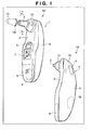
Fig. 1 shows a perspective view of the exterior of an ear-type thermometer 1 according to a first embodiment of the present invention seen from the probe side (1A), and from the operation switch side (1B). -
Fig. 2 is an exploded view of the ear-type thermometer shown inFig. 1 . -
Fig. 3 is a diagram which explains operation of a probecover attachment tool 11 which attaches aprobe cover 10. -
Fig. 4 is a cross-section view along X-X surface shown inFig. 1(1A) after attachment of theprobe cover 10. -
Fig. 5 is an external perspective view of a part of adetection element housing 20. -
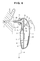
Fig. 6 is a cross-section view in which the ear-type thermometer 1 is being inserted to a measurement site. -
Fig. 7 shows a cross-section view showing placement of a mechanical contact switch as a probecover detection switch 60 that functions when contact is made against aninner perimeter surface 10k of the probe cover 10 (7A), a cross-section view showing placement of an electrical contact switch as the probecover detection switch 60 placed on aninner side surface 34 of aprobe 3 that functions when contact is made against aconductive layer 66 laid on theinner perimeter surface 10k of the probe cover 10 (7B), and a cross-section view showing placement of an optical switch as the probecover detection switch 60 comprising a light-guidingtube 99 between aprobe opening 31 and ahole 24 and detects areflective layer 67 laid out on aflange portion 10f of theprobe cover 10 using reflected light (7C). -
Fig. 8 is a block diagram of the ear-type thermometer 1. -
Fig. 9 is a flowchart explaining operation of a main routine program. -
Fig. 10 is a block diagram of another embodiment of the ear-type thermometer 1. -
Fig. 11 shows a flowchart explaining operation of a battery insertion program (11A), a flowchart explaining operation of an interrupt processing program (11B), and a flowchart explaining operation of an off-routine program. -
Fig. 12 is a flowchart explaining operation of a main routine program (11C). -
- 1
- ear-type thermometer
- 2
- main body base
- 3
- probe
- 4
- main body cover
- 5
- power switch
- 6
- measurement switch
- 7
- liquid crystal display unit
- 8
- button battery
- 9
- button battery cover
- 10
- probe cover
- 11
- probe cover attachment tool
- 12
- speaker
- 13
- LED element
- 15
- mounting board
- 20
- detection element housing
- 21
- temperature detection element
- 22
- infrared detection element
- 23
- mounting base member
- 24
- hole
- 25
- container member
- 26
- window member
- 28
- lead port
- 30
- wire
- 31
- opening
- 32
- end face
- 33
- locking part
- 34
- inner side surface
- 60
- probe cover detection switch (detection means)
- Embodiments of the present invention will be explained below with reference to accompanying figures.
- In
Fig.1, 1A is an external perspective view of an ear-type thermometer 1 of an embodiment of the present invention seen from the probe side. And, 1B is an external perspective view of the ear-type thermometer seen from anoperation switch 5 side. - In these figures, the ear-
type thermometer 1 has the design and weight which allow easy operation by one hand. For this reason, the ear-type thermometer 1 is divided into amain body base 2 and amain body cover 4 which are made by injection molding with a particular resin material, and is structured such that a mounting board to be discussed later can be fixed in the interior. Further, themain body base 2 and themain body cover 4 are formed from resin materials stained in different colors. In particular, themain body cover 4 is made from a semi-transparent resin, and is structured to allow viewing of blinking of two, internally placed light emittingLED elements 13 from the outside. As for resin materials that can be used, so-called engineering plastic including polyethylene, polypropylene, polyolefins such as ethylene-vinyl acetate polymer, and polyesters including polyethylene terephthalate and polybutylene terephthalate, can be thought of. - A
probe 3, which is inserted into the aural cavity (auditory canal) in order to detect infrared light emitted from a temperature measurement site (in particular, preferably the ear drum and/or its periphery) within the aural cavity, is formed as a conical cylinder with its tip having an external diameter of approximately 7 mm, and is integrally molded as a single unit with the above-mentionedmain body base 2. Thisprobe 3 can also be prepared as a separate component from themain body base 2, which simplifies an imposition step that will be explained later. - With reference to
Fig. 1(1A) , aprobe cover 10, shown in dash-dotted line and has a shape identical to a part of theprobe 3, is removably attached to theprobe 3. This probe cover 10 prevents ear wax and other foreign matters from entering through the opening and into theprobe 3, and is designed to be washable in alcohol and water on a regular basis when removed in order to maintain good hygienic condition. This probe cover 10 is typically prepared from polyethylene or polypropylene, olefin-type resins that transmit infrared light, to a predetermined thickness of, for example, 0.1 to 0.005mm by vacuum molding. However, other types of resin materials can also be used. -
Flange portion 10f is integrally molded on theprobe cover 10 as shown in the figure, and theprobe cover 10 is removably attached to theprobe 3 by having the flange portion held in place with a probecover attachment tool 11 as will be explained later. Further, the probecover attachment tool 11 has a tapered shape with a diameter larger than the base of theprobe 3 as shown in the figure, in order to prevent over-insertion of theprobe 3 into the aural cavity at the probecover attachment tool 11. - In
Fig. 1(1A) , a button for apower switch 5 that can be pressed for operation is placed below theprobe 3. Also, below thispower switch 5 a liquidcrystal display unit 7 is placed which displays measured temperature using 7 segments, and characters such as icons which indicate the measurement is starting. Placed below this liquidcrystal display unit 7 is abutton battery cover 9 which can be removed from and attached to themain body base 2 when replacing abutton battery 8 shown in dotted line. - On the other hand, in
Fig. 1(1B) , ameasurement switch 6 is placed at a location on themain body cover 4 which is approximately the back side of theprobe 3. Further, apiezoelectric speaker 12 shown in dotted line is fixed on the back side surface of themain body cover 4. -
Fig. 2 is an exploded view of the ear-type thermometer shown inFig.1 . In this figure, structures which are already explained and their parts are assigned the same numbers. On themain body cover 4, there is a depressed portion formed with anopening 4a which is to fix themeasurement switch 6 in place. By inserting a pair ofhooks 6a into theopening 4a and engaging them onto the edges of the back surface of theopening 4a, themeasurement switch 6 is retained and fixed in place. After fixation, themeasurement switch 6 can be moved back and forth in relation to themain body cover 4, which enables pressing and operating of amechanical contact switch 6a that includes a tact switch mounted on a main mountingsurface 15a of a mountingboard 15. Further, on the back side of themain body cover 4, thepiezoelectric speaker 12 shown in dotted line is fixed in advance, andwires 30 to thespeaker 12 extend from the main mountingsurface 15a of the mountingboard 15. - In proximity to the edges of the inner perimeter surface of the
main body cover 4, there are 4 pieces ofprotrusions 4f shown in dotted line symmetrically placed. Further, there is a hook-catchingpart 4k formed at the top. On the other hand, themain body base 2 forms edges which are identical in shape to the edges of themain body cover 4, and has integrally moldeddepressions 2f at locations corresponding to theprotrusions 4f, each having a groove into which therespective protrusion 4f fit. Further, the upper portion of themain body base 2 has an integrally moldedhook 2k which locks into thehook catching part 4k. - With the structures described above, it is possible to put together the
main body cover 4 and themain body base 2 without using any adhesive or screws, first by engaging thehooks 2k into thehook catching part 4k which determine relative positions of the two pieces, and subsequently engaging each of theprotrusions 4f into theirrespective depressions 2f. - Because the mounting
board 15 is fixed onto the interior of themain body base 2 which is surrounded by edges, it has a shapedportion 15f which is of a similar shape that approximately traces the edge walls of themain body base 2 as shown in the figure. On the main mountingsurface 15a of the mountingboard 15, the above-mentionedLED elements 13, a CPU element, and various types of electronic components are mounted. Further, on asub-mounting surface 15b on the back side of the mountingboard 15, amechanical switch 5a shown in dotted line, the above-mentioned liquid crystal display unit and a battery box into which thebutton battery 8 is set, are mounted. Further,wires 30 connected to adetection element housing 20, to be explained later, are also connected to thissub-mounting surface 15b. - A
screw hole 15c and afixation hole 15h, for fixing the mountingboard 15 onto themain body base 2, are respectively drilled at positions indicated in the figure. On the other hand,attachment studs main body base 2 at positions that correspond to thescrew hole 15c and thefixation hole 15h. The two attachment studs are configured such that the mountingboard 15 can be fixed onto themain body base 2 by aligning thescrew hole 15c andfixation hole 15 onto the studs and screwing ascrew 39 into theattachment stud 2b. In order to integrally mold themain body base 2 and theprobe 3 together, anopening 2a, which is connected to the inner perimeter surface of theprobe 3, is formed. - On the
main body cover 2, adepression having holes 2c for fixing thepower switch 5 in place is formed. By inserting a pair ofhooks 5a formed on thepower switch 5 into theholes 2c and engaging the hooks onto the back side of edges of theholes 2c, the switch is retained in place. After fixing the switch in place, thepower switch 5 can be moved back and forth in relation to themain body base 2, which enables pressing and operating of amechanical switch 5a, a tact switch mounted onto thesub-mounting surface 15b of the mountingboard 15. - Further, on the
main body cover 2, anopening 2d is formed which correspond to the location of the liquidcrystal display unit 7. Also, in order to allow replacement of thebutton battery 8, anopening 2g which is larger than the external dimensions of thebutton battery 8 is formed, and abutton battery cover 9 which covers thisopening 2g is slidably attached. - As explained above, by fixing, on the
main body cover 2, the mountingboard 15 onto which various components are mounted, and subsequently engaging themain body cover 4, assembly is completed. - On the other hand, the
probe cover 10 is set onto theprobe 3 in the direction indicated by an arrow such that it covers the probe. Subsequently, the probe cover can be fixed in place by placing theprobe attachment tool 11 and turning it in a direction indicated by the two arrows. -
Fig. 3 is a diagram which explains the relationship between the probecover attachment tool 11 for removably attaching theprobe cover 10 and theprobe 3 which is integrally molded with themain body base 2. In this figure, the probecover attachment tool 11 is prepared by injection molding as a cylindrical member using a resin material of a color different from that of themain body base 2, forming an opening which has astep 11b that makes contact with theflange portion 10f of the probe cover 10 (shown in dotted lines) and holds the cover in place. On the outer perimeter surface of thisprobe attachment tool 11, there are grippingportions 11c placed symmetrically which are gripped by finger tips and allow the probe attachment tool to be turned in the direction indicated by arrows. - Further, at locations which are at 90° from the gripping
portions 11c, there are lockingprotrusions 11d (one is shown in dotted lines) formed to protrude towards the outside. Further, in the center of each lockingprotrusion 11d, a lockinggroove 11k is formed. - On the other hand, a
step 2x, which makes contact with the bottom surface of theflange 10f of the probe cover 10 (shown in dotted and dashed lines) at a location corresponding to the bottom of theprobe 3, is integrally formed on themain body cover 2 and is concentric with theprobe 3. Further,inner sleeves 2y are integrally formed to surround thestep 2x, with agap 2w in between themselves and thestep 2x and being concentric with theprobe 3. At the center of theseinner sleeves 2y, there areprotrusions 2t shown in dotted lines which lock into the lockinggrooves 11k positioned at the center of the lockingprotrusions 11d. - According to the above-discussed structure, the
probe 3 is covered with theprobe cover 10, and the probecover attachment tool 11 is lowered onto theprobe 3 by gripping it at thegripping portions 11c. By inserting lockingprotusions 11d (one is shown in dotted lines) into large radius gaps 2wk in between theinner sleeves 2y and turning theattachment tool 11 counter-clockwise, the lockinggrooves 11k at the center of lockingprotrusions 11d are locked onto theprotrusions 2t, preventingprobe 3 from being released. - With the operation described above, the state depicted in the cross section diagram of
Fig. 1 following attachment of theprobe cover 10 ofFig. 4 is achieved. In other words, as shown inFig. 4 , by having the bottom surface of theflange portion 10f of the probe cover 10 (shown in a dotted-dashed line) make contact with thestep 2x, and the top surface of theflange portion 10f make contact with thestep 11b of the probecover attachment tool 11, theprobe cover 10 is sandwiched from above and below. Further, for example when theprobe cover 10 is to be removed for cleaning in water, the above-described operation is performed in reverse. - As depicted in the cross-section diagram of
Fig. 4 ,probe 3 is formed with the end face which is configured to have theopening 31 at its tip, the inner side surface having a hollow cylindrical shape and is continuous with theopening 2a of themain body base 2. Thedetection element housing 20 is fixed at the tip of theprobe 3 which is formed as depicted in the figure, and thisdetection element housing 20 is connected to the mountingboard 15 viawires 30. Alternatively, a connector which is not shown in the figure is used for making the connection to perform body temperature measurement to be discussed later. - The outer diameter of the tip of the
probe 3 is approximately 7 mm, due to the fact that it has to be inserted into the outer ear. For this reason, in order to fix thedetection element housing 20 at the position indicated in the figure, the outer diameter of thehousing 20 is set to be 5mm and its height is set to be around 4 mm. -
Fig. 5 is an external perspective view of thedetection element housing 20 wherein a part of thehousing 20 is removed for view into the interior. In thedetection element housing 20 of this figure, athermistor 21 which is a temperature detection element that detects ambient temperature, aninfrared detection element 22 which detects infrared light emitted from the temperature measurement site within the aural cavity, are mounted on a mountingmember 23. Thethermistor 21 which is fixed in such a manner, has been tweaked during the production stage to be able to measure ambient temperature of the usage environment, which is an absolute temperature. For this reason, the mountingmember 23 is made from a material which is a good conductor such as aluminum, which allows transmittance of external temperature and fixes thethermistor 21 to make its mounting surface large. Lead wires of thethermistor 21 are connected to electrode leads 28 which are fixed in place on and insulated from the mountingmember 23. - On the other hand, the
infrared detection element 22 which detects infrared radiation (IR) is not capable of detecting absolute temperature but can only detect relative temperature change. For this reason, body temperature is attained by adding the temperature detected by the infrared detection element to the temperature detected by the temperature detection element. Details of such detection operation is explained in, for example, Japanese Patent Laid-Open No.H11-123179 - In
Fig. 5 , since theinfrared detection element 22 preferably is a thermocouple-type (thermopile type) device, it is comprised ofhot junctions 22a andcold junctions 22b forming the shape of petals of a flower on top of awafer substrate 22c fixed onlegs 23b of the mountingmember 23. Each of the hot junctions and cold junctions are formed with different types of metals and are connected in series, and lead wires are connected to the electrode leads 29 which are fixed to and insulated from the mountingmember 23, as depicted in the figure. Further, an area H which are surrounded by thehot junctions 22a is painted in black to facilitate absorption of infrared radiation, allowing generation of electromotive force at each of the junctions to detect relative temperature change. - The semi-cross-section of
Fig. 5 depicts acontainer member 25 having a cylindrical shape with anouter perimeter surface 25a on its sidewall, ahole 24 on its ceiling plane and surrounding the two detection elements. Thiscontainer member 25 is also made of a metal with good conductance such as aluminum and stainless steel, like the mountingmember 23, and allows the external temperature to be transmitted to thethermistor 21. Further, awindow member 26 made from a ceramic material which lets through infrared light is fixed on thehole 24, and comprises thedetection element housing 20. - According to the
detection element housing 20 depicted in the figure, the mountingmember 23 has a radially extendingouter sleeve 23a formed along its entire perimeter, the backside of which is used as fixation portion. However, thedetection element housing 20 can be configured with a mountingmember 23 without thesleeve 23a and having the same diameter as theouter perimeter surface 25a of thecontainer member 25. Further, at least 2 protrusions in radial direction can be formed. -
Fig. 6 is a cross-section view in which the ear-type thermometer 1 is being inserted to aural cavity Y which is a measurement site. In this figure, parts that are already explained will be assigned the same numbers as before and their explanations will be omitted. When thepower switch 5 is turned on, the ear-type thermometer 1 remains in a standby until the ambient temperature is detected by thethermistor 21. The standby time for this measurement is the time required for display of an icon to be completed on the liquidcrystal display unit 7. After the standby time has elapsed, theprobe 3 is to be inserted into the aural cavity Y as illustrated. When doing so, over-insertion into the aural cavity is prevented by a distance Y between the probecover attachment tool 11 and the tip of the probe. - After insertion, by pressing the
measurement switch 6 theLED elements 13 will flash in sequence, and thespeaker 12 will generate a beep notifying completion of measurement. Subsequently, body temperature is displayed on the liquidcrystal display unit 7 for user to see. In particular, since themeasurement switch 6 is placed on the opposite side from theprobe 3, the design allows easy understanding of where theprobe 3 is to be inserted into when one is measuring body temperature of oneself. Further, when thethermometer 1 is left with thepower switch 5 turned on, the power automatically turns off, preventing consumption of battery. -
Fig. 7 shows cross-sections depicting examples of a probecover detection switch 60 which detects presence and absence of theprobe cover 10.Fig.7 (7A) shows usage of a mechanical contact switch operates by making contact with theinner perimeter surface 10k of theprobe cover 10 as the probecover detection switch 60.Fig.7 (7B) shows use of an electric contact switch as the probecover detection switch 60 placed on theinner side surface 34 of theprobe 3 which operates by making contact with aconductive layer 66 laid on theinner perimeter surface 10k of the probe cover.Fig.7 (7C) shows use of an optical switch as the probecover detection switch 60, wherein alight guiding tube 99 is placed between the opening 31 of the probe and thedetection element housing 20 and wherein the optical switch detects areflection layer 67 laid on theflange portion 10f of theprobe cover 10 using light reflection. - First, in
Fig.7 (7A), by inserting thedetection element housing 20 into theprobe 3 such that theopening 31 gets blocked, thewindow member 26 of thedetection element housing 20 is placed towards the top as shown in the figure, and the back surface of the mountingmember 23 locks with the lockingpart 33 and fixes thehousing 20 in place. Theopening 31 of theprobe 3 is formed at the top portion of a chamfered surface 32c at theend face 32 of theprobe 3 as shown in the figure, and is integrally molded in the shape of a circle with a diameter of approximately 3 to 4 mm. - This end face 32 is formed as an inner flange portion which protrudes inwards from the
inner side surface 34, and forms a flat ring-shaped inner wall. Grooves (not shown) having an outer diameter which is smaller than the inner diameter of theinner side surface 34 may be formed on this inner wall, which holds an O-ring that works as a sealing member (not shown). - On the other hand, in order to form the height of the
end face 32 reaches the height in which the height of thewindow member 26 is added to the height of theouter perimeter surface 25a of thecontainer member 25 of thedetection element housing 20 explained usingFig. 5 ,3 locking parts 33 of a height of about 1 to 2 mm are formed at locations separated from the inner wall separated by 120° from each other. These lockingparts 33 can be formed as a continuous structure that spans the entire circumference, or can be formed at 2 or more than 4 locations. - In the structure described above, the
detection element housing 20 connected withwires 30 to the electrode leads 28 and 29 and the back side of the mountingboard 23 is moved upwards using a tool not shown in the figure, the edges of thecontainer member 25 makes contact with the slanted surfaces of the lockingparts 33. If thehousing 20 is moved further upward, theouter perimeter surface 25a of thecontainer member 25 is guided by the top of the lockingparts 33, and thesleeve 23a of the mounting member 23 (refer toFig. 5 ) makes contact with the slanted surface. If thehousing 20 is moved even further upwards, the edge of thesleeve 23a is pushed into the slanted surface of the locking parts, and elastically deforms theprobe 3 in the radial direction. When further moved up, the surface of thewindow member 26 of thedetection element housing 20 makes contact with theend face 32 such that it blocks theopening 31 of theprobe 3 as shown inFig. 7(7A) . Further, when using an O-ring (gasket), the portion protruding out of the groove is elastically deformed, allowing maintenance of a liquid-tight state. - On the
inner side surface 34 of theprobe 3, ahole 34x is drilled, and anactuator member 61 is placed which protrudes out of this hole in a radial direction. Thisactuator member 61 is placed such that it protrudes to the outside by the action of acompressed coil spring 62 which is inserted in between theactuator member 61 and a tact switch, a mechanical contact switch acting as the probecover detection switch 60. On the other hand, adepression 11w is provided on the probecover attachment tool 11 in order to accommodate the tip of theactuator member 61 at a protruded position when there is noprobe cover 10. According above-discussed structure, when the probecover attachment tool 11 is set as discussed above and sandwich theflange portion 10f of the probe cover, theactuator member 61 makes contact against theinner perimeter surface 10k of theprobe cover 10 and presses the probecover detection switch 60. Further, when probe cover 10 is not set, theactuator member 61 moves to the protruded position by the action of thecompressed coil spring 62, and the probecover detection switch 60 is released from the pressed state. - As described above, utilizing the space that is generated from placing the
detection element housing 20 at the tip of theprobe 3, it is possible to make accurate detection of presence/absence of aprobe cover 10. - For
Fig. 7(7B) , parts that are already explained will be assigned the same numbers as before and their explanations will be omitted. In this figure, on the inner side surface 34 a pair of electric contact points is provided as the probecover detection switch 60. At the same time, aconductive layer 66 having a ring shape is laid on theinner perimeter surface 10k of the probe cover, and when theprobe cover 10 is set as shown in the figure the pair of electric contacts are connected and conducts electricity, allowing detection of presence of the probe cover. When there is noprobe cover 10, electricity is not conducted, and it is possible to detect absence of the cover. - In
Fig. 7(7C) , thelight guiding tube 99 comprising a gold gilt coverreflective surface 70 is placed between the opening of theprobe 3 and thehole 24 of thedetection element housing 20. Further, an optical switch which detects thereflective layer 67 laid on theflange portion 10f of theprobe cover 10 using reflected light, is placed on the mountingboard 15 as a probecover detection switch 60. - In the structure described above, when the
probe cover 10 is set as shown in the figure and light from a light emitting element is reflected off thereflective layer 67 which is detected by a light receiving element, it is possible to detect that a probe cover is present. When there is noprobe cover 10, no reflection of light occurs, and absence of probe cover is detected. -
Fig. 8 is a block diagram of the ear-type thermometer 1. Parts that are already explained will be assigned the same numbers as before and their explanations will be omitted. Thethermistor 21, which is installed in thedetection element housing 20 depicted in dotted line in the figure, is connected via thewires 30 to anamplifier 53 mounted on the mountingboard 15. Also, theinfrared detection element 22 which detects infrared radiation IR is connected via thewires 30 to anamplifier 54 mounted on the mountingboard 15. - Further, the probe
cover detection switch 60 is connected to a port of acontrol unit 50 mounted on the mountingboard 15. Thecontrol unit 50 mounted on the mountingboard 15 comprises a CPU element, a RAM 51 (Random Access Memory) which is a storage element and astorage unit 52 comprised of a ROM (read only memory). Thisstorage unit 52 comprises astorage unit 52a for storing a second temperature conversion coefficient for when there is no probe cover, and astorage unit 52a for storing a first temperature conversion coefficient for when there is a probe cover. The first and second temperature conversion coefficients are calculated by the temperature calibration with the probe cover on and probe cover off, respectively, and these temperature conversion coefficients are calculated by the temperature calibration which calculates correlation coefficient between the detected body temperature signals based on detection results of the two detection elements and actual body temperature signals based on actual body temperature, and these temperature conversion coefficients are used for measuring correct body temperature by correction which perform temperature conversion by the temperature calibration. - Further, the
control unit 50 is connected to theLED element 13, the liquidcrystal display unit 7 having a standby and temperature displaying parts, thespeaker 12 which a warning unit, thepower switch 5, and themeasurement switch 6. Further, it is structured to be supplied with electric power from thepower supply 8 which is the button battery. Further, the liquidcrystal display unit 7 has a measurement standby/temperature display portion 7a and a probe cover usagecount display portion 7b. - An exemplary control method for controlling the ear-type thermometer having the above-described configuration by detecting presence/absence of the probe cover and performing correction based on the detection results in order to eliminate errors in body temperature measurement result, will be explained with reference to an accompanying explanatory flow chart.
-
Fig. 9 is a flow chart which explains operation of a main routine program. In this figure, turning on of thepower switch 5 is waited for to be turned on at step S1. When thepower switch 5 is turned on, the process moves to step S2 and the main routine is started, in which initialization processing such as reading out cover usage count from the storage unit and displaying the usage count on thedisplay portion 7b. Subsequently the process moves to step S3, and in order to indicate that the process is currently at a standby status prior to measurement, for example, an icon or a character is displayed gradually on thedisplay portion 7a, starting from a small part, over a period of time that is required to complete the icon or character during which the standby status continues. During this time, measurement of ambient temperature by thethermistor 21 is performed. - Subsequently, at step S4, the
measurement switch 6 is waited for to be turned on. When it is determined that themeasurement switch 6 is pressed at step S42, the process advances to step S5 and detects electronic temperature signals from each of thedetector elements 22. Then, at step S6 it is checked whether the probecover detection switch 60 is turned on or not. When the probecover detection switch 60 is determined to be in a turned-on state at step S6, it is determined that theprobe cover 10 is properly attached, and the process advances to step S7 and reads the first temperature conversion coefficient. Then the process advances to S9 and obtains a body temperature by temperature conversion based on the first temperature conversion coefficient which was read at step S7. Next, at step S10, display of body temperature on thedisplay portion 7a is performed. And at step S11, a notice of completion of body temperature is performed, and the processing finishes. - On the other hand, if it is determined at step S6 that the probe
cover detection switch 60 is in a turned-off state, theprobe cover 10 is determined not to be attached, in which case the process advances to step S8 and reads the second temperature conversion coefficient from thestorage unit 52a. Subsequently, the process advances to step S9, in which a body temperature is obtained by temperature conversion based on the read second temperature conversion coefficient. Then at step S10, the body temperature is displayed on thedisplay portion 7a. And at step S11, a notice of completion of body temperature is performed, and the processing finishes. At this point, when the usage count of the probe cover is determined to have exceeded the usage count limit of, for example, 50 times, then an instruction to replace the cover is displayed on thedisplay portion 7b. -
Fig. 10 is a block diagram of the ear-type thermometer 1 according to a different embodiment. Parts that are already explained will be assigned the same numbers as before and their explanations will be omitted. According to this figure, thethermistor 21 installed in thedetection element housing 20 shown in dashed lines is connected to theamplifier 53 mounted on the mountingboard 15 via thewires 30. Further, theinfrared detection element 22 which detects infrared light IR is connected to theamplifier 54 mounted on the mountingboard 15 via thewires 30. - Also, the probe
cover detection switch 60 is connected to a port of thecontrol unit 50 mounted on the mountingboard 15. Thecontrol unit 50 mounted on the mountingboard 15 comprises the CPU element, the RAM 51 (Random Access Memory) which is a storage element and thestorage unit 52 comprised of a ROM (read only memory). Thisstorage unit 52 comprises astorage unit 152a for storing temperature conversion coefficients, and astorage unit 152b which stores probe cover usage count, ct. Further, thecontrol unit 50 is connected to theLED elements 13, thedisplay unit 7 having standby-display and temperature-display portions, thespeaker 12 which functions as an alerting unit, thepower switch 5, and themeasurement switch 6. Further, thecontrol unit 50 is configured to receive supply of electric power from thepower supply 8, which is a button battery, and operate. Additionally, the liquidcrystal display unit 7 has the measurement standby/temperature display portion 7a and the probe cover usagecount display portion 7b.
Next, an exemplary operation will be explained using each of accompanying flow charts. - In
Fig. 11 , 11A is a flow chart explaining operation of a battery insertion program. In this figure, when the battery insertion program is started and anew button battery 8 is inserted after anold button battery 8 has run out, reset is released at step S1 and the process advances to step S2 in which initialization processing such as initial configuration of ports and clearance of the RAM (random access memory) are carried out. Subsequently, at step S3, erase of "ON code" of the RAM is performed, and the display portion of the liquidcrystal display unit 7 is turned off at step S4. This "ON code" is a code used to discriminate whether power supply operation is a power ON operation or a power OFF operation by referring to it after the power supply operation. When an "ON code" is written, the operation is determined to be an OFF operation. When the "ON code" is not written, the operation is determined to be an OFF operation. - Next, the process advances to step S5 and allows interrupt by the
power switch 5, and transitions to the sleep status in step S6. In other words, the program is stopped, and is put in a status in which the program can only be started by interrupt by operating the power supply switch. The power switch interrupt will be automatically prohibited when release from reset state. The sleep status is a status in which the battery insertion program is stopped, and can only be deactivated by power supply switch interrupt. When thepower switch 5 is pressed, power switch interrupt is generated and an interrupt processing program is performed. - In
Fig. 11 , 11B shows a flow chart which explains operation of the interrupt processing program. In this figure, when thepower supply switch 5 is pressed at step S7, the interrupt processing program starts. The process advances to step S8 and it is checked whether an "ON code" is written into the RAM. When it is checked there is no "ON code" written into the RAM at step S8, the process advances to step S9 and an "ON code" is written, and then the process advances to step S10 and jumps to a main routine program that will be discussed later. On the other hand, when it is checked at step S8 that an "ON code" is written, the process advances to step S11 and erases the "ON code", and then further advances to step S12 at which point the process jumps to the main routine program. - In the flow chart explaining the operation of an off routine program shown in
Fig. 11 (11C), power supply switch interrupt is prohibited once at step S13, and the process advances to step S14 in which the display portion of the liquid crystal display unit is turned off. Subsequently, at step S15, the usage count ct of theprobe cover 10 is written into the storage unit. Then, at step S16, termination processing, such as processing of ports and turning off an analog power supply, is performed, after which the process cuts into step S4 ofFig. 11 (11A), thereby allowing power supply switch interrupt and stands by in the sleep status. -
Fig. 12 is a flow chart explaining operation of the main routine program. In this figure, when the power is turned on, the main routine starts. At step S20 the cover usage count ct is read from the storage unit, and the process advances to step S21 in which display indicating that the thermometer is in a measurement standby status using, for example, an icon, is performed on the liquid crystal device. Subsequently, at step S22, pressing of themeasurement switch 6 is waited for. When it is determined at step S22 that themeasurement switch 6 is pressed, the process advances to step S23 and detects electric temperature signals from each of thedetection elements cover detection switch 60 is in an ON status, and determines that theprobe cover 10 is properly attached when the detection switch is in the ON status. Then the process advances to step S25, and a temperature conversion coefficient is read out from the storage unit. - The process advances to step S26 and a body temperature which is measured by temperature conversion based on the read-in temperature conversion coefficient is obtained. Subsequently, at step S27, 1 is added to the probe cover usage count ct stored in the RAM and is stored back in the RAM. At step S29, the body temperature obtained from step S26 is displayed, and at step S29 an alert notifying completion of temperature detection is performed with the
speaker 12, and pressing of the measurement switch is awaited for the subsequent round of measurement. - The process continues on to step S30, and determination of whether the usage count ct has exceeded the usage count limit X, for example, 50 times, is performed, and if the usage count does not exceed the limit the process returns to step S22. Further, if it is determined at step S30 that the usage count has exceeded the usage count limit X, the process advances to step S31 and prompts exchange of the probe cover by generating an alarm sound from the
speaker 12, which is an alerting means, and completes processing. Alternatively, the process can be forced to stop, and a message instructing replacement can be displayed on the liquid crystal display unit and usage thereafter can be prohibited (step S32)
On the other hand, at step S24 if it is determined that the probecover detection switch 60 is turned off, it is determined that theprobe cover 10 is removed and clears the probe cover usage count ct stored in the RAM to zero. Then the process advances to step S34 and displays an instruction to attach theprobe cover 10, and then awaits pressing of the measurement switch. - With each of the programs discussed above, it is possible to correctly update the cover usage count ct even when the button battery is removed. Further, while the power is turned on, the updating of the probe cover usage count ct is only performed in the RAM regardless of how many times measurement is made, preventing excessive writing in the storage unit. In other words, the determination unit, by comprising a storage unit which preferentially stores usage count regardless of whether power supply is loaded or not, is capable of correctly updating the cover usage count ct.
- The present invention is not limited to the above-described embodiments, and can be modified in various ways within the sprit and scope of the invention. Accordingly, appended claims are provided to make the scope of the present invention known.
Claims (15)
- An ear-type thermometer having a probe formed with a probe opening at its tip which houses a temperature detection element which detects ambient temperature and an infrared detection element which detects infrared light emitted from a temperature measurement site within the aural cavity, and measures body temperature based on detection results from said two detection elements, the ear-type thermometer comprising:a probe cover which can be detachably provided onto said probe and covers said probe opening;a detection means which detects attachment/detachment of said probe cover onto said probe; anda correction means which corrects, based on the detection result of said detection means, body temperature which is measured based on detection results of said two detection elements.
- An ear-type thermometer according to claim 1, comprising:a probe cover attachment tool which fixes said probe cover in a state attached to said probe, said probe having an end face formed to have said probe opening, an inner side surface of a hollow cylindrical body, and a locking part which protrudes inward from said inner side surface,a detection element housing body which includes a mounting base member onto which said two detection elements are fixed, a cylindrical container member fixed to said mounting base member which surrounds said two detection elements and has a hole which orients said two detection elements towards said opening, and a window member attached on top of and blocks said hole, and transmits infrared radiation through,wherein said window member of said detection element housing body contacts said end face on the side of said detection elements so as to cover said probe opening, and said mounting base member is fixed by said engagement part, andwherein said detection means includes a mechanical contact switch which is placed on said inner side surface and makes contact against the inner perimeter surface of said probe cover, an electric contact switch which is placed on said inner side surface and makes contact against a conductive layer which is laid on the inner perimeter surface of said probe cover, or an optical switch which is placed on said inner side surface and detects reflected light from a reflective layer which is laid on the inner perimeter surface of said probe cover.
- An ear-type thermometer according to claim 1, comprising:a probe cover attachment tool which fixes said probe in an attached state by locking in a flange portion of said probe cover,;a detection element housing body placed on a mounting board which includes a mounting base member onto which said two detection elements are fixed, and a cylindrical container member fixed to said mounting base member which surrounds said two detection elements and has a hole which orients said infrared detection element; anda light guiding tube placed between said probe opening and said hole,wherein said detection means is placed on said mounting board and include an optical switch which detects a reflective layer laid on said flange portion using reflection of light.
- An ear-type thermometer according to any one of preceding claims, further comprising a main body cover which covers a liquid crystal display unit that performs display of body temperature measurement results, wherein said probe is formed as a single unit with said main body cover such that said probe is on the same side as said liquid crystal display unit.
- An ear-type thermometer according to claim 1, wherein:said correction means performs temperature correction which calculates correlation coefficient between detected temperature signal based on the detection results of said two detection elements and actual body temperature signal based on actual body temperature,and said correction means also performs temperature conversion using a first temperature conversion coefficient calculated by applying said temperature correction in a state without said probe cover and a second temperature conversion coefficient calculated by applying said temperature correction in a state with said probe cover.
- A method of controlling an ear-type thermometer which measures body temperature based on detection results of a temperature detection element which detects ambient temperature, and an infrared detection element which detects infrared lights emitted from a temperature measurement site within the aural cavity, said two detection elements placed within a probe having a probe opening at its tip, comprising:a step of detecting whether a probe cover, which can be freely attached and detached onto and from said probe and covers said probe opening, is attached or detached by a detection means; anda step of correcting, based on the detection result of said detection means, body temperature based on detection results from said two detection element.
- A computer readable storage medium stored with a program for measuring body temperature based on detection results of a temperature detection element which detects ambient temperature, and an infrared detection element which detects infrared lights emitted from a temperature measurement site within the aural cavity, said two detection elements placed within a probe having a probe opening at its tip, comprising;a program for a step of detecting whether a probe cover, which can be freely attached and detached onto and from said probe and covers said probe opening, is attached or detached by a detection means; anda program for a step of correcting, based on the detection result of said detection means, body temperature based on detection results from said two detection element.
- An ear-type thermometer having a probe formed with a probe opening at its tip which houses a temperature detection element which detects ambient temperature and an infrared detection element which detects infrared light emitted from a temperature measurement site within the aural cavity, and measures body temperature based on detection results from said two detection elements, comprising:a probe cover which can be freely attached and detached onto and from said probe and covers said probe opening;a detection means which detects attachment/detachment of said probe cover onto said probe;a correction means which corrects, based on the detection result of said detection means, body temperature based on detection results of said two detection elements;a determination means which determines whether or not said probe cover has been used more than a usage count limitation based on the actual usage count; andan alert means or a display means for alerting need to replace said probe cover when the determination result from said determination means exceeds said usage count limitation.
- An ear-type thermometer according to claim 8, comprising:a probe cover attachment tool which fixes said probe cover to said probe in a state attached to said probe, said probe having an end face formed to have said probe opening, an inner side surface of a hollow cylindrical body, and a locking part which protrudes inwards from said inner side surface,a detection element housing body which includes a mounting base member onto which said two detection elements are fixed, a cylindrical container member fixed to said mounting base member, surrounds said two detection elements, and has a hole which orients said two detection elements towards said opening, a cylindrical window member attached on top of and blocks said hole, and passes infrared light through, wherein said window member of said detection element housing body contacts said end face on the side of said detection elements such that said probe opening is blocked while said mounting base member is fixed in place by said engagement part,wherein said detection means includes a mechanical contact switch which is placed on said inner side surface and makes contact against the inner perimeter surface of said probe cover, an electric contact switch which is placed on said inner side surface and makes contact against a conductive layer which is laid on the inner perimeter surface of said probe cover, or an optical switch is placed on said inner side surface and detects reflected light from a reflective layer which is laid on the inner perimeter surface of said probe cover.
- An ear-type thermometer according to claim 8, comprising:a probe cover attachment tool which fixes said probe in an attached state by locking in a flange portion of said probe cover;a detection element housing mounted onto a mounting board, and including a mounting base member for fixing said two detection elements, a cylindrical container member having a hole facing said infrared detection element while being fixed to said mounting base member and surrounding said two detection elements; anda light guiding tube placed between said probe opening and said hole, wherein said detection means is placed on top of said mounting board and includes an optical switch which detects a reflective layer laid on said flange portion using reflection of light.
- An ear-type thermometer according to any one of claims 8 to 10, further comprising:a main body cover which covers a liquid crystal display unit that performs display of body temperature measurement results, wherein said probe is formed as a single unit with said main body cover such that said probe is on the same side as said liquid crystal display unit.
- An ear-type thermometer according to claim 8 wherein:said correction means performs temperature correction which calculates correlation coefficient between detected temperature signal based on the detection results of said two detection elements and actual body temperature signal based on actual body temperature,and said correction means also performs temperature conversion using a first temperature conversion coefficient calculated by applying said temperature correction in a state without said probe cover and a second temperature conversion coefficient calculated by applying said temperature correction in a state with said probe cover.
- An ear-type thermometer according to claim 8, wherein said determination means comprises a storage means which preferentially stores said usage count regardless of whether a power supply means is loaded or not.
- A method of controlling an ear-type thermometer which measures body temperature based on detection results of a temperature detection element which detects ambient temperature, and an infrared detection element which detects infrared lights emitted from a temperature measurement site within the aural cavity, said two detection elements placed within a probe having a probe opening at its tip, comprising:a step of detecting whether a probe cover, which can be freely attached and detached onto and from said probe and covers said probe opening, is attached or detached by a detection means;a step of correcting, based on the detection result of said detection means, body temperature based on detection results from said two detection element;a step of determining whether or not said probe cover has been used more than a usage count limitation based on the actual usage count with said determination means; anda step of alerting need to replace said probe cover when the determination result from said determination means exceeds said usage count limitation by an alerting means.
- A computer readable storage medium stored with a program for measuring body temperature based on detection results of a temperature detection element which detects ambient temperature, and an infrared detection element which detects infrared lights emitted from a temperature measurement site within the aural cavity, said two detection elements placed within a probe having a probe opening at its tip, comprising;
a program for a step of detecting whether a probe cover, which can be freely attached and detached onto and from said probe and covers said probe opening, is attached or detached from a detection means;
a program for a step of correcting, based on the detection result of said detection means, body temperature based on detection results from said two detection element;
a program for a step of determining whether or not said probe cover has been used more than a usage count limitation based on the actual usage count by said determination means; and
a program for a step of alerting need to replace said probe cover when the determination result from said determination means exceeds said usage count limitation with by an alerting means.
Applications Claiming Priority (2)
| Application Number | Priority Date | Filing Date | Title |
|---|---|---|---|
| JP2007080124A JP5053674B2 (en) | 2007-03-26 | 2007-03-26 | Ear thermometer |
| PCT/JP2008/054581 WO2008117670A1 (en) | 2007-03-26 | 2008-03-13 | Ear clinical thermometer and its control method |
Publications (2)
| Publication Number | Publication Date |
|---|---|
| EP2130488A1 true EP2130488A1 (en) | 2009-12-09 |
| EP2130488A4 EP2130488A4 (en) | 2013-12-11 |
Family
ID=39788406
Family Applications (1)
| Application Number | Title | Priority Date | Filing Date |
|---|---|---|---|
| EP08738652.0A Withdrawn EP2130488A4 (en) | 2007-03-26 | 2008-03-13 | AURICULAR MEDICAL THERMOMETER AND ITS CONTROL METHOD |
Country Status (6)
| Country | Link |
|---|---|
| US (1) | US8126672B2 (en) |
| EP (1) | EP2130488A4 (en) |
| JP (1) | JP5053674B2 (en) |
| CN (1) | CN101646383B (en) |
| TW (1) | TW200843693A (en) |
| WO (1) | WO2008117670A1 (en) |
Cited By (2)
| Publication number | Priority date | Publication date | Assignee | Title |
|---|---|---|---|---|
| CN102335015A (en) * | 2010-07-14 | 2012-02-01 | 泰尔茂株式会社 | Female thermometer |
| EP2690358A4 (en) * | 2011-03-24 | 2014-09-17 | Olympus Corp | Illuminating system |
Families Citing this family (29)
| Publication number | Priority date | Publication date | Assignee | Title |
|---|---|---|---|---|
| US8308355B2 (en) * | 2008-07-29 | 2012-11-13 | Welch Allyn, Inc. | Cycle counting |
| WO2010078219A1 (en) * | 2008-12-29 | 2010-07-08 | Kaz Europe Sa | Probe cover with matching feature for a medical thermometer |
| KR101668905B1 (en) * | 2009-10-05 | 2016-10-24 | 카즈 유럽 에스에이 | Multi-site attachments for ear thermometers |
| US8374683B2 (en) * | 2009-12-30 | 2013-02-12 | Ray D. Stone | Medical instrument with probe, probe cover, and methods of using the same |
| JP2012070919A (en) * | 2010-09-28 | 2012-04-12 | Terumo Corp | Ear thermometer |
| JP2012249655A (en) * | 2011-05-31 | 2012-12-20 | Sony Corp | Optical probe, covering member, measurement method for optical probe, and optical power meter |
| US8996096B2 (en) | 2011-07-19 | 2015-03-31 | Welch Allyn, Inc. | Systems and methods for determining patient temperature |
| US20130083823A1 (en) * | 2011-09-29 | 2013-04-04 | Covidien Lp | Electronic thermometer with image sensor and display |
| US8949065B2 (en) * | 2011-09-30 | 2015-02-03 | Covidien Lp | Capacitive sensor for thermometer probe |
| US8292500B1 (en) | 2011-09-30 | 2012-10-23 | Tyco Healthcare Group Lp | IR sensor for electronic thermometer |
| US8651736B2 (en) | 2012-02-03 | 2014-02-18 | Welch Allyn, Inc. | Probe cover container identification |
| WO2013159301A1 (en) * | 2012-04-25 | 2013-10-31 | Zhao Zhigang | Method for reminding cleaning of infrared thermometer |
| JP6051693B2 (en) * | 2012-09-03 | 2016-12-27 | セイコーエプソン株式会社 | Ultrasonic probe, electronic device and ultrasonic diagnostic apparatus |
| TWM453480U (en) * | 2012-10-11 | 2013-05-21 | Avita Corp | Body temperature measuring device |
| DE102012223691A1 (en) * | 2012-12-19 | 2014-06-26 | Heine Optotechnik Gmbh & Co Kg | Otoscope with disposable ear funnel |
| US9645013B2 (en) * | 2013-03-15 | 2017-05-09 | Helen Of Troy Limited | Thermometer user interface |
| CN103263254A (en) * | 2013-05-07 | 2013-08-28 | 宫文峰 | Portable electronic thermometer |
| CA2912816A1 (en) * | 2013-06-19 | 2014-12-24 | F. Hoffmann-La Roche Ag | Combination of ro5503781 and capecitabine for cancer therapy |
| US9587985B2 (en) | 2013-08-08 | 2017-03-07 | Sharp Kabushiki Kaisha | Optical transmission device, light guide plug, optical fiber plug, light reception device, and portable apparatus |
| CN103439003B (en) * | 2013-09-03 | 2016-08-31 | 重庆大学 | A kind of method improving infrared measurement of temperature precision |
| EP3078951A1 (en) * | 2015-04-10 | 2016-10-12 | Silverlight AG | Device with a pir sensor |
| CN106225956A (en) * | 2016-08-31 | 2016-12-14 | 芜湖天宇科技开发有限公司 | Temperature sensor multichannel resistance monitor station and detection method thereof |
| CN106343968A (en) * | 2016-10-11 | 2017-01-25 | 南阳市第二人民医院 | Electronic ear thermometer |
| CN106303091A (en) * | 2016-10-19 | 2017-01-04 | 广东小天才科技有限公司 | Method and device for switching loudspeaker states of mobile terminal |
| DE102018008622B4 (en) * | 2018-10-31 | 2020-10-01 | Sartorius Stedim Biotech Gmbh | Bioprocess container with optical measuring device |
| CN112629663B (en) * | 2019-09-20 | 2025-05-02 | 卡西欧计算机株式会社 | Detection device and method for manufacturing the detection device |
| CN111928948A (en) * | 2020-07-31 | 2020-11-13 | 安徽汉诺医疗科技有限公司 | Medical infrared thermometer and use method thereof |
| CN112674728B (en) * | 2020-12-22 | 2023-07-04 | 河南国立微智能研究院有限公司 | Bluetooth wireless body temperature monitoring device |
| WO2024151677A1 (en) * | 2023-01-10 | 2024-07-18 | Cue Health Inc. | Temperature measurement system |
Family Cites Families (15)
| Publication number | Priority date | Publication date | Assignee | Title |
|---|---|---|---|---|
| US5018872A (en) * | 1988-11-01 | 1991-05-28 | Diatek, Inc. | Probe assembly for infrared thermometer |
| US5411032A (en) * | 1993-06-18 | 1995-05-02 | Infra-Temp Inc. | Electronic thermometer probe cover |
| DE19543096C2 (en) * | 1995-11-18 | 1998-07-23 | Braun Ag | Infrared radiation thermometer |
| JP2000500371A (en) * | 1995-11-18 | 2000-01-18 | ブラウン アクチェンゲゼルシャフト | Infrared thermometer and method for evaluating a signal provided by an infrared sensor of an infrared thermometer |
| CN100394885C (en) * | 1997-07-16 | 2008-06-18 | 泰尔茂株式会社 | Earplug Medical Thermometer |
| JPH11104086A (en) * | 1997-09-30 | 1999-04-20 | Minolta Co Ltd | Thermometer |
| JP3615372B2 (en) * | 1997-10-21 | 2005-02-02 | テルモ株式会社 | Infrared thermometer |
| US6522912B1 (en) * | 1998-05-06 | 2003-02-18 | Matsushita Electric Industrial Co., Ltd. | Ear type thermometer |
| JP3514138B2 (en) * | 1998-09-29 | 2004-03-31 | テルモ株式会社 | Probe cover removal mechanism and ear thermometer |
| JP2000131146A (en) * | 1998-10-28 | 2000-05-12 | Omron Corp | Electronic thermometer |
| JP2000217788A (en) * | 1999-02-01 | 2000-08-08 | Matsushita Electric Ind Co Ltd | Radiation thermometer |
| JP2001349787A (en) * | 2000-06-06 | 2001-12-21 | Seiko Epson Corp | Infrared detector and thermometer |
| EP1302761B1 (en) * | 2000-06-13 | 2014-08-06 | Omron Healthcare Co., Ltd. | Pyrometer |
| JP3945189B2 (en) * | 2001-06-01 | 2007-07-18 | オムロンヘルスケア株式会社 | Infrared thermometer |
| KR100571811B1 (en) * | 2003-05-09 | 2006-04-17 | 삼성전자주식회사 | Boundary signal measuring device |
-
2007
- 2007-03-26 JP JP2007080124A patent/JP5053674B2/en not_active Expired - Fee Related
-
2008
- 2008-03-13 WO PCT/JP2008/054581 patent/WO2008117670A1/en not_active Ceased
- 2008-03-13 EP EP08738652.0A patent/EP2130488A4/en not_active Withdrawn
- 2008-03-13 CN CN2008800100820A patent/CN101646383B/en not_active Expired - Fee Related
- 2008-03-20 TW TW097109746A patent/TW200843693A/en unknown
-
2009
- 2009-09-25 US US12/567,354 patent/US8126672B2/en not_active Expired - Fee Related
Cited By (4)
| Publication number | Priority date | Publication date | Assignee | Title |
|---|---|---|---|---|
| CN102335015A (en) * | 2010-07-14 | 2012-02-01 | 泰尔茂株式会社 | Female thermometer |
| EP2690358A4 (en) * | 2011-03-24 | 2014-09-17 | Olympus Corp | Illuminating system |
| US9261261B2 (en) | 2011-03-24 | 2016-02-16 | Olympus Corporation | Illumination system |
| US10041655B2 (en) | 2011-03-24 | 2018-08-07 | Olympus Corporation | Illumination system |
Also Published As
| Publication number | Publication date |
|---|---|
| WO2008117670A1 (en) | 2008-10-02 |
| TW200843693A (en) | 2008-11-16 |
| JP5053674B2 (en) | 2012-10-17 |
| EP2130488A4 (en) | 2013-12-11 |
| JP2008237396A (en) | 2008-10-09 |
| CN101646383A (en) | 2010-02-10 |
| CN101646383B (en) | 2011-09-28 |
| US8126672B2 (en) | 2012-02-28 |
| US20100017163A1 (en) | 2010-01-21 |
Similar Documents
| Publication | Publication Date | Title |
|---|---|---|
| US8126672B2 (en) | Ear-type thermometer and a control method thereof | |
| TWI383777B (en) | Ear plug-in type clinical thermometer | |
| JP3646652B2 (en) | Infrared thermometer | |
| AU2010239577B2 (en) | Calibrated assembly for IR thermometer apparatus | |
| US6612735B2 (en) | Infrared ray clinical thermometer | |
| US8996096B2 (en) | Systems and methods for determining patient temperature | |
| JPWO2000022978A1 (en) | infrared thermometer | |
| CN103815882B (en) | Infra-red thermometer | |
| JP2004533618A (en) | Temperature probe adapter | |
| JPH0320630A (en) | Device for displaying state of operation of fermenter | |
| KR100898216B1 (en) | Electronic thermometer with sensor location | |
| JP2011062370A (en) | Ear type clinical thermometer | |
| JP2008241364A (en) | Ear thermometer | |
| JP3770265B2 (en) | Infrared thermometer | |
| JP3160911U (en) | Ear thermometer | |
| JP2008237397A (en) | Ear thermometer and control method thereof | |
| JP3160910U (en) | Ear thermometer | |
| CN201269778Y (en) | Ear thermometer and probe head thereof | |
| JP2008241362A (en) | Ear thermometer and method for manufacturing ear thermometer | |
| JP3160909U (en) | Ear thermometer | |
| CN105030211B (en) | Rapid temperature measuring instrument and temperature measuring control method thereof | |
| JPH11104086A (en) | Thermometer | |
| US20080075144A1 (en) | Display assembly of a digital thermometer | |
| CN205458618U (en) | Body temperature detection device | |
| JP2011062369A (en) | Ear type clinical thermometer |
Legal Events
| Date | Code | Title | Description |
|---|---|---|---|
| PUAI | Public reference made under article 153(3) epc to a published international application that has entered the european phase |
Free format text: ORIGINAL CODE: 0009012 |
|
| 17P | Request for examination filed |
Effective date: 20091015 |
|
| AK | Designated contracting states |
Kind code of ref document: A1 Designated state(s): AT BE BG CH CY CZ DE DK EE ES FI FR GB GR HR HU IE IS IT LI LT LU LV MC MT NL NO PL PT RO SE SI SK TR |
|
| DAX | Request for extension of the european patent (deleted) | ||
| A4 | Supplementary search report drawn up and despatched |
Effective date: 20131111 |
|
| RIC1 | Information provided on ipc code assigned before grant |
Ipc: G01J 5/00 20060101ALI20131105BHEP Ipc: G01J 5/04 20060101ALI20131105BHEP Ipc: G01J 5/02 20060101ALI20131105BHEP Ipc: G01J 5/08 20060101ALI20131105BHEP Ipc: A61B 5/01 20060101AFI20131105BHEP Ipc: G01J 5/06 20060101ALI20131105BHEP |
|
| STAA | Information on the status of an ep patent application or granted ep patent |
Free format text: STATUS: THE APPLICATION IS DEEMED TO BE WITHDRAWN |
|
| 18D | Application deemed to be withdrawn |
Effective date: 20140611 |