EP2130433A1 - Angler's method feeder mould - Google Patents
Angler's method feeder mould Download PDFInfo
- Publication number
- EP2130433A1 EP2130433A1 EP09251474A EP09251474A EP2130433A1 EP 2130433 A1 EP2130433 A1 EP 2130433A1 EP 09251474 A EP09251474 A EP 09251474A EP 09251474 A EP09251474 A EP 09251474A EP 2130433 A1 EP2130433 A1 EP 2130433A1
- Authority
- EP
- European Patent Office
- Prior art keywords
- mould
- feeder
- cavity
- ground bait
- bait
- Prior art date
- Legal status (The legal status is an assumption and is not a legal conclusion. Google has not performed a legal analysis and makes no representation as to the accuracy of the status listed.)
- Granted
Links
Images

Classifications
-
- A—HUMAN NECESSITIES
- A01—AGRICULTURE; FORESTRY; ANIMAL HUSBANDRY; HUNTING; TRAPPING; FISHING
- A01K—ANIMAL HUSBANDRY; AVICULTURE; APICULTURE; PISCICULTURE; FISHING; REARING OR BREEDING ANIMALS, NOT OTHERWISE PROVIDED FOR; NEW BREEDS OF ANIMALS
- A01K97/00—Accessories for angling
- A01K97/04—Containers for bait; Preparation of bait
Definitions
- This invention relates to method feeder moulds for assisting anglers to form ground bait balls around method feeders, to produce a uniform and compacted shape of bait around the feeder.
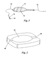
- Modern day anglers increasingly use a method of fishing that incorporates a weighted feeder 10 as shown in Figure 1 of the accompanying drawings, loaded with a ball of small bait particles that have been mixed together with water to form what is termed as 'ground bait'.
- the feeder 10 comprises a frame with open spaces into and around which the bait 11 may be compacted so that it adheres to the feeder. Tied to the feeder 10 at one end is the fishing line 12 running to the angler's rod, and at the other end is a short length of fishing line 14 with a hook 16 tied on and a hook bait 18 attached.
- This setup is commonly known as a 'method feeder' fishing rig.
- the above described 'method feeder' rig is cast by the angler into the targeted area of water, it then sinks to the bottom of the lake or river. As soon as the rig enters the water the ground bait particles begin to break up and dissolve and disperse in to the surrounding water due to saturation of the lake water into the ground bait, and this process continues as the rig lies on the lakebed.
- This invention seeks to provide a more effective mould for the forming of ground bait on to feeders, by adding a feature which enables the baited feeder to be removed from a mould without loss of bait from the feeder.
- this invention provides a method feeder mould comprising a mould body having a mould surface or surfaces defining an open mould cavity, wherein at least a part of the surface or surfaces are moveable to assist release in use of a loaded ground bait feeder from the mould.
- the cavity is preferably of generally concave form.
- the cavity conveniently has a rounded base from which upstands a side wall of generally parallel-sided from and parallel to the axis of movement of the movable surface or surfaces.
- the movable surface or surfaces are preferably biased towards a moulding position and moveable against the bias to a release position.
- the movable surface or surfaces are provided on an element slidably movable with respect to the mould body.
- the element may include a concave portion which cooperates with a sidewall on the mould body to provide the mould surfaces.
- the mould surface may be formed as a shell including a zone or region of weakness whereby manual pressure on the shell remote form the mould surface causes distortion of the mould surface to assist release.
- the zone or region of weakness may conveniently comprise a line of thinner section around said base defining an annular flexible web that allows the base of the mould to move upwards relative to the upper part of the mould, with the base itself retaining some rigidity.
- the mould body may have two grooves at opposite edges of said mould cavity and generally in a plane transverse to the release direction, for receiving the opposite ends of a feeder in use.
- the mould body may include further opposed sets of two grooves at opposite edges of said mould cavity generally in a plane transverse of the release direction, for receiving the opposite ends of a feeder in use at one of a number of different respective orientations relative to the mould cavity.
- this invention provides a method of applying ground bait to a feeder, which comprises introducing said feeder and an amount of ground bait into the cavity of a method feeder mould to compact the ground bait against the feeder, and moving a portion of the wall of the cavity to assist release of the ground bait and feeder from said mould.
- a movable floor is provided in the feeder mould base, so that after the feeder is loaded with bait and sitting in the mould, the position of the floor of the mould is then raised, by the angler pressing it up from beneath the mould.
- the invention provides a method feeder mould with a moveable floor in the mould base, whereby in use a feeder loaded with bait and sitting in the mould may be released by moving the floor.
- the action of raising the floor of the mould reduces the surface area of the mould that is in contact with the ground bait, therefore giving the ground bait around the feeder more adhesion to the feeder in comparison to its adhesion to the mould.
- the baited feeder can then be removed from the mould without leaving bait inside the mould.
- the movable mould floor may be spring loaded so that, after it has been pressed up by the angler to release the baited feeder, it returns to its original position at the bottom of the mould, ready to accept a new charge of ground bait.
- the method feeder comprises a body in the form of a moulded plastics shell 22 defining a half-ovoid shaped moulding cavity 24.
- the shell stops short of the base of the cavity and a moveable mould floor 26 is mounted for sliding movement in the body between the moulding position shown in Figure 3(a) and the release position shown in Figure 3(b) .
- the mould floor is biased to the moulding position of Figure 3(a) .
- the angler fills the mould with ground bait or pellets 11 and then firmly presses the feeder 10 into the mould so that the ground bait or pellets compact and adhere to the feeder.
- the moveable floor 26 is then pushed upwardly as shown in Figure 3(b) to shift the formed mass of ground bait upwardly in the mould to release it from the outer periphery of the mould surface.
- the feeder and moulded ground bait can then be eased off the mould.
- Figure 4 illustrates a slight variation to the arrangement shown in Figures 3(a) and 3(b) .
- the moveable element 28 is a false floor in the mould cavity which has two legs which protrude through the cavity wall each carrying a biasing spring 32 and being connected by a common push plate 34 so as to bias the floor into its lower (moulding) position as shown.
- the peripheral wall region 36 of the fixed mould cavity that contacts the bait is generally vertical so that the removal action is one of sliding over rather then pulling away from the surface.
- the mould cavity is made up by moulding a shell 40 which has a weakened region 42 extending around the mould about a third of the way up.
- the weakened section 42 may be produced by locally thinning the wall so that it is resiliently deformable so that, as in the previous embodiments, when the base 44 of the mould is pushed upwardly, the mould mass is pushed away from contact at the edge of the mould so that the compacted mould mass and feeder can be lifted out without causing disintegration of the mould mass.
- the pushing of the mould not only lifts the mould mass away from the mould at the periphery but it can also help to release surface suction in the lower part of the mould.
- the resilience of the mould shell material is such as to return the mould to its moulding position shown in Figure 6 (a) when released.
- a pair of diametrically opposed grooves 46 are provided at opposite ends of the mould cavity for receiving the ends of the feeder.
- further pairs of grooves, 48, 48', 48" may be provided around the periphery of the mould to allow the feeder to be disposed at different angular positions within the mould.
Landscapes
- Life Sciences & Earth Sciences (AREA)
- Environmental Sciences (AREA)
- Animal Husbandry (AREA)
- Biodiversity & Conservation Biology (AREA)
- Feeding And Watering For Cattle Raising And Animal Husbandry (AREA)
Abstract
Description
- This invention relates to method feeder moulds for assisting anglers to form ground bait balls around method feeders, to produce a uniform and compacted shape of bait around the feeder.
- Modern day anglers increasingly use a method of fishing that incorporates a
weighted feeder 10 as shown inFigure 1 of the accompanying drawings, loaded with a ball of small bait particles that have been mixed together with water to form what is termed as 'ground bait'. Thefeeder 10 comprises a frame with open spaces into and around which thebait 11 may be compacted so that it adheres to the feeder. Tied to thefeeder 10 at one end is thefishing line 12 running to the angler's rod, and at the other end is a short length offishing line 14 with ahook 16 tied on and ahook bait 18 attached. This setup is commonly known as a 'method feeder' fishing rig. - The above described 'method feeder' rig is cast by the angler into the targeted area of water, it then sinks to the bottom of the lake or river. As soon as the rig enters the water the ground bait particles begin to break up and dissolve and disperse in to the surrounding water due to saturation of the lake water into the ground bait, and this process continues as the rig lies on the lakebed.
- Fish are attracted to the feeder rig by the small bait particles and begin to feed on them. At some stage during this feeding period a fish will take the bait that is attached to the hook length and become hooked.
- Previously anglers have used
plain moulds 20 as shown inFigure 2 to assist in the forming of ground bait around method feeders, but these are only effective if the consistency of the moisture of the ground bait is mixed perfectly. If the ground bait mix is too wet or too dry the ground bait sticks to the mould instead of the feeder when the angler attempts to remove the feeder from the mould. It will be appreciated that the plain curved mould recess causes a suction effect that tends to place the moulded bait in tension as the feeder is removed from the mould, and so the pulling action can cause the bait mass to weaken or disintegrate. - This invention seeks to provide a more effective mould for the forming of ground bait on to feeders, by adding a feature which enables the baited feeder to be removed from a mould without loss of bait from the feeder.
- Accordingly in one aspect this invention provides a method feeder mould comprising a mould body having a mould surface or surfaces defining an open mould cavity, wherein at least a part of the surface or surfaces are moveable to assist release in use of a loaded ground bait feeder from the mould.
- The cavity is preferably of generally concave form. Thus the cavity conveniently has a rounded base from which upstands a side wall of generally parallel-sided from and parallel to the axis of movement of the movable surface or surfaces. The movable surface or surfaces are preferably biased towards a moulding position and moveable against the bias to a release position.
- The movement required may be achieved in a number of different ways. Thus in one arrangement the movable surface or surfaces are provided on an element slidably movable with respect to the mould body. Here the element may include a concave portion which cooperates with a sidewall on the mould body to provide the mould surfaces. Alternatively the mould surface may be formed as a shell including a zone or region of weakness whereby manual pressure on the shell remote form the mould surface causes distortion of the mould surface to assist release. The zone or region of weakness may conveniently comprise a line of thinner section around said base defining an annular flexible web that allows the base of the mould to move upwards relative to the upper part of the mould, with the base itself retaining some rigidity.
- The mould body may have two grooves at opposite edges of said mould cavity and generally in a plane transverse to the release direction, for receiving the opposite ends of a feeder in use. To allow different feeders and/or different orientations of feeder, the mould body may include further opposed sets of two grooves at opposite edges of said mould cavity generally in a plane transverse of the release direction, for receiving the opposite ends of a feeder in use at one of a number of different respective orientations relative to the mould cavity.
- In another aspect this invention provides a method of applying ground bait to a feeder, which comprises introducing said feeder and an amount of ground bait into the cavity of a method feeder mould to compact the ground bait against the feeder, and moving a portion of the wall of the cavity to assist release of the ground bait and feeder from said mould.
- In preferred embodiments a movable floor is provided in the feeder mould base, so that after the feeder is loaded with bait and sitting in the mould, the position of the floor of the mould is then raised, by the angler pressing it up from beneath the mould.
- In yet another aspect the invention provides a method feeder mould with a moveable floor in the mould base, whereby in use a feeder loaded with bait and sitting in the mould may be released by moving the floor.
- The action of raising the floor of the mould reduces the surface area of the mould that is in contact with the ground bait, therefore giving the ground bait around the feeder more adhesion to the feeder in comparison to its adhesion to the mould. The baited feeder can then be removed from the mould without leaving bait inside the mould.
- The movable mould floor may be spring loaded so that, after it has been pressed up by the angler to release the baited feeder, it returns to its original position at the bottom of the mould, ready to accept a new charge of ground bait.
- Whilst the invention has been described above it extends to any inventive combination of the features set out above or in the following description or claims.
- The invention may be performed in various ways and, by way of example only, certain specific embodiments will now be described, reference being made to the accompanying drawings, in which:-
-
Figure 1 is a view of a method feeder loaded with compacted ground bait and attached to a fishing line; -
Figure 2 is a perspective view of a known form of method feeder mould; -
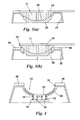
Figures 3(a) and 3(b) are longitudinal section views through a mould feeder of this invention with a moveable floor in the moulding position and the release position respectively; -
Figure 4 is a section view of an arrangement similar to that ofFigure 4 but with a false floor; -
Figure 5 is a perspective view of a method feeder mould in accordance with a second embodiment of this invention; -
Figures 6(a) and (b) are cross-sections through the method feeder mould ofFigure 5 when in the moulding and release positions respectively, and -
Figure 7 is a top plan view of a method feeder mould in accordance with a third embodiment of the invention. - Referring initially to the first embodiment, the method feeder comprises a body in the form of a moulded
plastics shell 22 defining a half-ovoid shapedmoulding cavity 24. The shell stops short of the base of the cavity and amoveable mould floor 26 is mounted for sliding movement in the body between the moulding position shown inFigure 3(a) and the release position shown inFigure 3(b) . The mould floor is biased to the moulding position ofFigure 3(a) . - In use the angler fills the mould with ground bait or
pellets 11 and then firmly presses thefeeder 10 into the mould so that the ground bait or pellets compact and adhere to the feeder. Themoveable floor 26 is then pushed upwardly as shown inFigure 3(b) to shift the formed mass of ground bait upwardly in the mould to release it from the outer periphery of the mould surface. The feeder and moulded ground bait can then be eased off the mould. -
Figure 4 illustrates a slight variation to the arrangement shown inFigures 3(a) and 3(b) . Here themoveable element 28 is a false floor in the mould cavity which has two legs which protrude through the cavity wall each carrying a biasingspring 32 and being connected by acommon push plate 34 so as to bias the floor into its lower (moulding) position as shown. It will be noted here that theperipheral wall region 36 of the fixed mould cavity that contacts the bait is generally vertical so that the removal action is one of sliding over rather then pulling away from the surface. - Referring now to the arrangement of
Figures 5 and 6 , here the mould cavity is made up by moulding ashell 40 which has a weakenedregion 42 extending around the mould about a third of the way up. The weakenedsection 42 may be produced by locally thinning the wall so that it is resiliently deformable so that, as in the previous embodiments, when thebase 44 of the mould is pushed upwardly, the mould mass is pushed away from contact at the edge of the mould so that the compacted mould mass and feeder can be lifted out without causing disintegration of the mould mass. As before, the pushing of the mould not only lifts the mould mass away from the mould at the periphery but it can also help to release surface suction in the lower part of the mould. In this arrangement, the resilience of the mould shell material is such as to return the mould to its moulding position shown inFigure 6 (a) when released. - Finally, referring to
Figure 7 , in the above embodiments, a pair of diametrically opposedgrooves 46 are provided at opposite ends of the mould cavity for receiving the ends of the feeder. As shown inFigure 7 further pairs of grooves, 48, 48', 48" may be provided around the periphery of the mould to allow the feeder to be disposed at different angular positions within the mould.
Claims (13)
- A method feeder mould comprising a mould body having a mould surface or surfaces (22) defining an open mould cavity (24), wherein at least a part (26, 44) of the surface or surfaces are moveable to assist release in use of a loaded ground bait feeder (10, 11) from the mould.
- A method feeder mould according to Claim 1, wherein the cavity (24) is of generally concave form.
- A method feeder mould according to Claim 1 or Claim 2, wherein the cavity (24) has a rounded base from which upstands a side wall (36) of generally parallel-sided form and parallel to the axis of movement of the movable surface or surfaces (26, 28, 44).
- A method feeder mould according to any of the preceding Claims, wherein the movable surface or surfaces (26, 28, 44) are biased towards a moulding position and moveable against the bias to a release position.
- A method feeder mould according to any preceding Claim, wherein the movable surface or surfaces (26, 28, 44) are provided on an element slidably movable with respect to the mould body.
- A method feeder mould according to Claim 5, wherein the element includes a concave portion (26, 28) which cooperates with a sidewall (36) on the mould body to provide the mould surfaces.
- A method feeder mould according to any preceding Claim, wherein the mould surface is integrally formed as a shell (40) and includes a zone or region (42) of weakness whereby manual pressure on the shell (44) remote from the mould surface causes distortion of the mould surface to assist release.
- A method feeder mould according to Claim 7, wherein said zone or region (42) of weakness comprises a line of thinner section around the shell wall defining the mould cavity.
- A method feeder mould according to any preceding Claim, wherein said mould body comprises two grooves (46) at opposite edges of said mould cavity and generally in a plane transverse to the release direction, for receiving the opposite ends of a feeder in use.
- A method feeder according to Claim 9, including further opposed sets (48, 48', 48") of two grooves at opposite edges of said mould cavity generally in a plane transverse of the release direction, for receiving the opposite ends of a feeder in use at one of a number of different respective angular orientations relative to the mould cavity.
- A method of applying ground bait to a feeder, which comprises introducing said feeder (10) and an amount of ground bait (11) into the cavity (24) of a method feeder mould to compact the ground bait against the feeder (10), and moving a portion (26) of the wall of the cavity to assist release of the ground bait and feeder from said mould.
- A method feeder mould, substantially as hereinbefore described, with reference to and as illustrated in any of Figures 3 to 7 of the accompanying drawings.
- A method of applying ground bait to a feeder substantially as hereinbefore described with reference to any of Figures 3 to 7 of the accompanying drawings.
Priority Applications (1)
| Application Number | Priority Date | Filing Date | Title |
|---|---|---|---|
| PL09251474T PL2130433T3 (en) | 2008-06-03 | 2009-06-03 | Angler's method feeder mould |
Applications Claiming Priority (1)
| Application Number | Priority Date | Filing Date | Title |
|---|---|---|---|
| GB0810071A GB0810071D0 (en) | 2008-06-03 | 2008-06-03 | Metod feeder mould |
Publications (2)
| Publication Number | Publication Date |
|---|---|
| EP2130433A1 true EP2130433A1 (en) | 2009-12-09 |
| EP2130433B1 EP2130433B1 (en) | 2018-02-14 |
Family
ID=39638044
Family Applications (1)
| Application Number | Title | Priority Date | Filing Date |
|---|---|---|---|
| EP09251474.4A Active EP2130433B1 (en) | 2008-06-03 | 2009-06-03 | Angler's method feeder mould |
Country Status (4)
| Country | Link |
|---|---|
| EP (1) | EP2130433B1 (en) |
| GB (1) | GB0810071D0 (en) |
| HU (1) | HUE037433T2 (en) |
| PL (1) | PL2130433T3 (en) |
Cited By (2)
| Publication number | Priority date | Publication date | Assignee | Title |
|---|---|---|---|---|
| GB2498739A (en) * | 2012-01-25 | 2013-07-31 | Catchum 88 Ltd | Mould for a method feeder |
| GB2499027A (en) * | 2012-02-03 | 2013-08-07 | Fox Int Group Ltd | A flexible method feeder mould |
Citations (4)
| Publication number | Priority date | Publication date | Assignee | Title |
|---|---|---|---|---|
| US2846803A (en) * | 1956-04-24 | 1958-08-12 | David F Rettig | Fish hook baiter |
| GB1299869A (en) * | 1969-04-18 | 1972-12-13 | Plastona Waddington Ltd John | Improvements relating to containers |
| WO1985003200A1 (en) * | 1984-01-28 | 1985-08-01 | Henry Thomas Spring | Bait punch |
| GB2403389A (en) * | 2003-07-04 | 2005-01-05 | John Paul Joseph Lucas | Bait compression apparatus |
Family Cites Families (1)
| Publication number | Priority date | Publication date | Assignee | Title |
|---|---|---|---|---|
| GB2175181A (en) | 1985-05-20 | 1986-11-26 | Drennan Peter John | Punch |
-
2008
- 2008-06-03 GB GB0810071A patent/GB0810071D0/en not_active Ceased
-
2009
- 2009-06-03 PL PL09251474T patent/PL2130433T3/en unknown
- 2009-06-03 HU HUE09251474A patent/HUE037433T2/en unknown
- 2009-06-03 EP EP09251474.4A patent/EP2130433B1/en active Active
Patent Citations (4)
| Publication number | Priority date | Publication date | Assignee | Title |
|---|---|---|---|---|
| US2846803A (en) * | 1956-04-24 | 1958-08-12 | David F Rettig | Fish hook baiter |
| GB1299869A (en) * | 1969-04-18 | 1972-12-13 | Plastona Waddington Ltd John | Improvements relating to containers |
| WO1985003200A1 (en) * | 1984-01-28 | 1985-08-01 | Henry Thomas Spring | Bait punch |
| GB2403389A (en) * | 2003-07-04 | 2005-01-05 | John Paul Joseph Lucas | Bait compression apparatus |
Cited By (3)
| Publication number | Priority date | Publication date | Assignee | Title |
|---|---|---|---|---|
| GB2498739A (en) * | 2012-01-25 | 2013-07-31 | Catchum 88 Ltd | Mould for a method feeder |
| GB2498739B (en) * | 2012-01-25 | 2014-03-12 | Catchum 88 Ltd | Mould for a method feeder |
| GB2499027A (en) * | 2012-02-03 | 2013-08-07 | Fox Int Group Ltd | A flexible method feeder mould |
Also Published As
| Publication number | Publication date |
|---|---|
| HUE037433T2 (en) | 2018-08-28 |
| GB0810071D0 (en) | 2008-07-09 |
| PL2130433T3 (en) | 2018-06-29 |
| EP2130433B1 (en) | 2018-02-14 |
Similar Documents
| Publication | Publication Date | Title |
|---|---|---|
| US20230210098A1 (en) | Fishing apparatus having construction for accomodating a scent attractant and system therefor | |
| EP2002954A3 (en) | Method and apparatus for injection compression molding using active material elements | |
| EP2130433B1 (en) | Angler's method feeder mould | |
| CA2620014A1 (en) | Void former | |
| US5685108A (en) | Fishhook | |
| KR20250051533A (en) | Fishing artificial bait made from natural fish skin for enhanced attraction | |
| CA2526960A1 (en) | Device for cutting out tissue specimens | |
| US20010015029A1 (en) | Tungsten fishing equipment and methods | |
| US4431394A (en) | Marshmallow mold | |
| EP1481592A3 (en) | Method of preparing roasted confectionery containing solid state center material | |
| JP2010057404A (en) | Lure and lure body | |
| JPH0872082A (en) | Method for producing fiber-reinforced plastic molded product | |
| KR200443512Y1 (en) | Fish cake maker | |
| JPH11501811A (en) | Eco-friendly fishing weight | |
| CN210782618U (en) | A fishing bait forming device | |
| JP2003165109A5 (en) | ||
| GB2175181A (en) | Punch | |
| JP3091149U (en) | Defoamer in concrete molding | |
| CA2324134A1 (en) | Pre-cast concrete slat | |
| CN216627192U (en) | Hand throwing positioning nest forming device | |
| JP3111265U (en) | Fishing bait molding machine | |
| JP2023031158A (en) | Salt package, manufacturing method of salt package and salt molding machine | |
| JPS6124349Y2 (en) | ||
| CN204860813U (en) | Three-dimensional biscuit forming mold | |
| JP3027638U (en) | Solid food for livestock |
Legal Events
| Date | Code | Title | Description |
|---|---|---|---|
| PUAI | Public reference made under article 153(3) epc to a published international application that has entered the european phase |
Free format text: ORIGINAL CODE: 0009012 |
|
| AK | Designated contracting states |
Kind code of ref document: A1 Designated state(s): AT BE BG CH CY CZ DE DK EE ES FI FR GB GR HR HU IE IS IT LI LT LU LV MC MK MT NL NO PL PT RO SE SI SK TR |
|
| RIN1 | Information on inventor provided before grant (corrected) |
Inventor name: PRESTON, DAVID |
|
| 17P | Request for examination filed |
Effective date: 20100521 |
|
| 17Q | First examination report despatched |
Effective date: 20100624 |
|
| APBK | Appeal reference recorded |
Free format text: ORIGINAL CODE: EPIDOSNREFNE |
|
| APBN | Date of receipt of notice of appeal recorded |
Free format text: ORIGINAL CODE: EPIDOSNNOA2E |
|
| APBR | Date of receipt of statement of grounds of appeal recorded |
Free format text: ORIGINAL CODE: EPIDOSNNOA3E |
|
| APAF | Appeal reference modified |
Free format text: ORIGINAL CODE: EPIDOSCREFNE |
|
| APBT | Appeal procedure closed |
Free format text: ORIGINAL CODE: EPIDOSNNOA9E |
|
| GRAP | Despatch of communication of intention to grant a patent |
Free format text: ORIGINAL CODE: EPIDOSNIGR1 |
|
| STAA | Information on the status of an ep patent application or granted ep patent |
Free format text: STATUS: GRANT OF PATENT IS INTENDED |
|
| INTG | Intention to grant announced |
Effective date: 20170922 |
|
| GRAS | Grant fee paid |
Free format text: ORIGINAL CODE: EPIDOSNIGR3 |
|
| GRAA | (expected) grant |
Free format text: ORIGINAL CODE: 0009210 |
|
| STAA | Information on the status of an ep patent application or granted ep patent |
Free format text: STATUS: THE PATENT HAS BEEN GRANTED |
|
| AK | Designated contracting states |
Kind code of ref document: B1 Designated state(s): AT BE BG CH CY CZ DE DK EE ES FI FR GB GR HR HU IE IS IT LI LT LU LV MC MK MT NL NO PL PT RO SE SI SK TR |
|
| REG | Reference to a national code |
Ref country code: GB Ref legal event code: FG4D |
|
| REG | Reference to a national code |
Ref country code: CH Ref legal event code: EP |
|
| REG | Reference to a national code |
Ref country code: IE Ref legal event code: FG4D |
|
| REG | Reference to a national code |
Ref country code: DE Ref legal event code: R096 Ref document number: 602009050725 Country of ref document: DE Ref country code: AT Ref legal event code: REF Ref document number: 969270 Country of ref document: AT Kind code of ref document: T Effective date: 20180315 |
|
| REG | Reference to a national code |
Ref country code: NL Ref legal event code: FP |
|
| REG | Reference to a national code |
Ref country code: FR Ref legal event code: PLFP Year of fee payment: 10 |
|
| PG25 | Lapsed in a contracting state [announced via postgrant information from national office to epo] |
Ref country code: ES Free format text: LAPSE BECAUSE OF FAILURE TO SUBMIT A TRANSLATION OF THE DESCRIPTION OR TO PAY THE FEE WITHIN THE PRESCRIBED TIME-LIMIT Effective date: 20180214 Ref country code: CY Free format text: LAPSE BECAUSE OF FAILURE TO SUBMIT A TRANSLATION OF THE DESCRIPTION OR TO PAY THE FEE WITHIN THE PRESCRIBED TIME-LIMIT Effective date: 20180214 Ref country code: HR Free format text: LAPSE BECAUSE OF FAILURE TO SUBMIT A TRANSLATION OF THE DESCRIPTION OR TO PAY THE FEE WITHIN THE PRESCRIBED TIME-LIMIT Effective date: 20180214 Ref country code: LT Free format text: LAPSE BECAUSE OF FAILURE TO SUBMIT A TRANSLATION OF THE DESCRIPTION OR TO PAY THE FEE WITHIN THE PRESCRIBED TIME-LIMIT Effective date: 20180214 Ref country code: NO Free format text: LAPSE BECAUSE OF FAILURE TO SUBMIT A TRANSLATION OF THE DESCRIPTION OR TO PAY THE FEE WITHIN THE PRESCRIBED TIME-LIMIT Effective date: 20180514 Ref country code: FI Free format text: LAPSE BECAUSE OF FAILURE TO SUBMIT A TRANSLATION OF THE DESCRIPTION OR TO PAY THE FEE WITHIN THE PRESCRIBED TIME-LIMIT Effective date: 20180214 |
|
| REG | Reference to a national code |
Ref country code: HU Ref legal event code: AG4A Ref document number: E037433 Country of ref document: HU |
|
| PG25 | Lapsed in a contracting state [announced via postgrant information from national office to epo] |
Ref country code: BG Free format text: LAPSE BECAUSE OF FAILURE TO SUBMIT A TRANSLATION OF THE DESCRIPTION OR TO PAY THE FEE WITHIN THE PRESCRIBED TIME-LIMIT Effective date: 20180514 Ref country code: SE Free format text: LAPSE BECAUSE OF FAILURE TO SUBMIT A TRANSLATION OF THE DESCRIPTION OR TO PAY THE FEE WITHIN THE PRESCRIBED TIME-LIMIT Effective date: 20180214 Ref country code: GR Free format text: LAPSE BECAUSE OF FAILURE TO SUBMIT A TRANSLATION OF THE DESCRIPTION OR TO PAY THE FEE WITHIN THE PRESCRIBED TIME-LIMIT Effective date: 20180515 Ref country code: LV Free format text: LAPSE BECAUSE OF FAILURE TO SUBMIT A TRANSLATION OF THE DESCRIPTION OR TO PAY THE FEE WITHIN THE PRESCRIBED TIME-LIMIT Effective date: 20180214 |
|
| PG25 | Lapsed in a contracting state [announced via postgrant information from national office to epo] |
Ref country code: EE Free format text: LAPSE BECAUSE OF FAILURE TO SUBMIT A TRANSLATION OF THE DESCRIPTION OR TO PAY THE FEE WITHIN THE PRESCRIBED TIME-LIMIT Effective date: 20180214 Ref country code: RO Free format text: LAPSE BECAUSE OF FAILURE TO SUBMIT A TRANSLATION OF THE DESCRIPTION OR TO PAY THE FEE WITHIN THE PRESCRIBED TIME-LIMIT Effective date: 20180214 |
|
| REG | Reference to a national code |
Ref country code: DE Ref legal event code: R026 Ref document number: 602009050725 Country of ref document: DE |
|
| PLBI | Opposition filed |
Free format text: ORIGINAL CODE: 0009260 |
|
| PG25 | Lapsed in a contracting state [announced via postgrant information from national office to epo] |
Ref country code: DK Free format text: LAPSE BECAUSE OF FAILURE TO SUBMIT A TRANSLATION OF THE DESCRIPTION OR TO PAY THE FEE WITHIN THE PRESCRIBED TIME-LIMIT Effective date: 20180214 Ref country code: SK Free format text: LAPSE BECAUSE OF FAILURE TO SUBMIT A TRANSLATION OF THE DESCRIPTION OR TO PAY THE FEE WITHIN THE PRESCRIBED TIME-LIMIT Effective date: 20180214 |
|
| PLAX | Notice of opposition and request to file observation + time limit sent |
Free format text: ORIGINAL CODE: EPIDOSNOBS2 |
|
| 26 | Opposition filed |
Opponent name: MIDDY TACKLE INTERNATIONAL LTD Effective date: 20181115 |
|
| REG | Reference to a national code |
Ref country code: CH Ref legal event code: PL |
|
| PG25 | Lapsed in a contracting state [announced via postgrant information from national office to epo] |
Ref country code: SI Free format text: LAPSE BECAUSE OF FAILURE TO SUBMIT A TRANSLATION OF THE DESCRIPTION OR TO PAY THE FEE WITHIN THE PRESCRIBED TIME-LIMIT Effective date: 20180214 |
|
| PG25 | Lapsed in a contracting state [announced via postgrant information from national office to epo] |
Ref country code: LU Free format text: LAPSE BECAUSE OF NON-PAYMENT OF DUE FEES Effective date: 20180603 Ref country code: MC Free format text: LAPSE BECAUSE OF FAILURE TO SUBMIT A TRANSLATION OF THE DESCRIPTION OR TO PAY THE FEE WITHIN THE PRESCRIBED TIME-LIMIT Effective date: 20180214 |
|
| PLBB | Reply of patent proprietor to notice(s) of opposition received |
Free format text: ORIGINAL CODE: EPIDOSNOBS3 |
|
| PG25 | Lapsed in a contracting state [announced via postgrant information from national office to epo] |
Ref country code: LI Free format text: LAPSE BECAUSE OF NON-PAYMENT OF DUE FEES Effective date: 20180630 Ref country code: CH Free format text: LAPSE BECAUSE OF NON-PAYMENT OF DUE FEES Effective date: 20180630 |
|
| REG | Reference to a national code |
Ref country code: AT Ref legal event code: UEP Ref document number: 969270 Country of ref document: AT Kind code of ref document: T Effective date: 20180214 |
|
| PGFP | Annual fee paid to national office [announced via postgrant information from national office to epo] |
Ref country code: CZ Payment date: 20190524 Year of fee payment: 11 Ref country code: IE Payment date: 20190628 Year of fee payment: 11 Ref country code: PL Payment date: 20190520 Year of fee payment: 11 Ref country code: NL Payment date: 20190626 Year of fee payment: 11 Ref country code: IT Payment date: 20190621 Year of fee payment: 11 |
|
| PGFP | Annual fee paid to national office [announced via postgrant information from national office to epo] |
Ref country code: BE Payment date: 20190627 Year of fee payment: 11 Ref country code: FR Payment date: 20190625 Year of fee payment: 11 Ref country code: HU Payment date: 20190524 Year of fee payment: 11 |
|
| PGFP | Annual fee paid to national office [announced via postgrant information from national office to epo] |
Ref country code: DE Payment date: 20190416 Year of fee payment: 13 Ref country code: AT Payment date: 20190521 Year of fee payment: 11 |
|
| PG25 | Lapsed in a contracting state [announced via postgrant information from national office to epo] |
Ref country code: MT Free format text: LAPSE BECAUSE OF NON-PAYMENT OF DUE FEES Effective date: 20180603 |
|
| PG25 | Lapsed in a contracting state [announced via postgrant information from national office to epo] |
Ref country code: TR Free format text: LAPSE BECAUSE OF FAILURE TO SUBMIT A TRANSLATION OF THE DESCRIPTION OR TO PAY THE FEE WITHIN THE PRESCRIBED TIME-LIMIT Effective date: 20180214 |
|
| PG25 | Lapsed in a contracting state [announced via postgrant information from national office to epo] |
Ref country code: PT Free format text: LAPSE BECAUSE OF FAILURE TO SUBMIT A TRANSLATION OF THE DESCRIPTION OR TO PAY THE FEE WITHIN THE PRESCRIBED TIME-LIMIT Effective date: 20180214 |
|
| PG25 | Lapsed in a contracting state [announced via postgrant information from national office to epo] |
Ref country code: MK Free format text: LAPSE BECAUSE OF NON-PAYMENT OF DUE FEES Effective date: 20180214 |
|
| PG25 | Lapsed in a contracting state [announced via postgrant information from national office to epo] |
Ref country code: IS Free format text: LAPSE BECAUSE OF FAILURE TO SUBMIT A TRANSLATION OF THE DESCRIPTION OR TO PAY THE FEE WITHIN THE PRESCRIBED TIME-LIMIT Effective date: 20180614 |
|
| REG | Reference to a national code |
Ref country code: DE Ref legal event code: R119 Ref document number: 602009050725 Country of ref document: DE |
|
| PG25 | Lapsed in a contracting state [announced via postgrant information from national office to epo] |
Ref country code: CZ Free format text: LAPSE BECAUSE OF NON-PAYMENT OF DUE FEES Effective date: 20200603 |
|
| REG | Reference to a national code |
Ref country code: NL Ref legal event code: MM Effective date: 20200701 |
|
| REG | Reference to a national code |
Ref country code: AT Ref legal event code: MM01 Ref document number: 969270 Country of ref document: AT Kind code of ref document: T Effective date: 20200603 |
|
| REG | Reference to a national code |
Ref country code: BE Ref legal event code: MM Effective date: 20200630 |
|
| PG25 | Lapsed in a contracting state [announced via postgrant information from national office to epo] |
Ref country code: NL Free format text: LAPSE BECAUSE OF NON-PAYMENT OF DUE FEES Effective date: 20200701 Ref country code: FR Free format text: LAPSE BECAUSE OF NON-PAYMENT OF DUE FEES Effective date: 20200630 Ref country code: HU Free format text: LAPSE BECAUSE OF NON-PAYMENT OF DUE FEES Effective date: 20200604 Ref country code: IE Free format text: LAPSE BECAUSE OF NON-PAYMENT OF DUE FEES Effective date: 20200603 |
|
| PG25 | Lapsed in a contracting state [announced via postgrant information from national office to epo] |
Ref country code: AT Free format text: LAPSE BECAUSE OF NON-PAYMENT OF DUE FEES Effective date: 20200603 Ref country code: BE Free format text: LAPSE BECAUSE OF NON-PAYMENT OF DUE FEES Effective date: 20200630 Ref country code: DE Free format text: LAPSE BECAUSE OF NON-PAYMENT OF DUE FEES Effective date: 20210101 |
|
| PG25 | Lapsed in a contracting state [announced via postgrant information from national office to epo] |
Ref country code: IT Free format text: LAPSE BECAUSE OF NON-PAYMENT OF DUE FEES Effective date: 20200603 |
|
| REG | Reference to a national code |
Ref country code: DE Ref legal event code: R100 Ref document number: 602009050725 Country of ref document: DE |
|
| PLCK | Communication despatched that opposition was rejected |
Free format text: ORIGINAL CODE: EPIDOSNREJ1 |
|
| PG25 | Lapsed in a contracting state [announced via postgrant information from national office to epo] |
Ref country code: PL Free format text: LAPSE BECAUSE OF NON-PAYMENT OF DUE FEES Effective date: 20200603 |
|
| PLBN | Opposition rejected |
Free format text: ORIGINAL CODE: 0009273 |
|
| STAA | Information on the status of an ep patent application or granted ep patent |
Free format text: STATUS: OPPOSITION REJECTED |
|
| 27O | Opposition rejected |
Effective date: 20211202 |
|
| PGFP | Annual fee paid to national office [announced via postgrant information from national office to epo] |
Ref country code: GB Payment date: 20260626 Year of fee payment: 18 |