EP2129971B1 - Method for controlling heating apparatus - Google Patents
Method for controlling heating apparatus Download PDFInfo
- Publication number
- EP2129971B1 EP2129971B1 EP08723381.3A EP08723381A EP2129971B1 EP 2129971 B1 EP2129971 B1 EP 2129971B1 EP 08723381 A EP08723381 A EP 08723381A EP 2129971 B1 EP2129971 B1 EP 2129971B1
- Authority
- EP
- European Patent Office
- Prior art keywords
- temperature
- heating
- room temperature
- heating apparatus
- overshoot
- Prior art date
- Legal status (The legal status is an assumption and is not a legal conclusion. Google has not performed a legal analysis and makes no representation as to the accuracy of the status listed.)
- Not-in-force
Links
- 238000010438 heat treatment Methods 0.000 title claims description 86
- 238000000034 method Methods 0.000 title claims description 43
- XLYOFNOQVPJJNP-UHFFFAOYSA-N water Substances O XLYOFNOQVPJJNP-UHFFFAOYSA-N 0.000 description 13
- 230000007423 decrease Effects 0.000 description 10
- 230000003247 decreasing effect Effects 0.000 description 3
- 238000010586 diagram Methods 0.000 description 2
- 239000000446 fuel Substances 0.000 description 2
- 238000002485 combustion reaction Methods 0.000 description 1
- 238000004891 communication Methods 0.000 description 1
- 230000000694 effects Effects 0.000 description 1
- 238000009434 installation Methods 0.000 description 1
- 238000012986 modification Methods 0.000 description 1
- 230000004048 modification Effects 0.000 description 1
Images


Classifications
-
- F—MECHANICAL ENGINEERING; LIGHTING; HEATING; WEAPONS; BLASTING
- F24—HEATING; RANGES; VENTILATING
- F24D—DOMESTIC- OR SPACE-HEATING SYSTEMS, e.g. CENTRAL HEATING SYSTEMS; DOMESTIC HOT-WATER SUPPLY SYSTEMS; ELEMENTS OR COMPONENTS THEREFOR
- F24D19/00—Details
- F24D19/10—Arrangement or mounting of control or safety devices
- F24D19/1006—Arrangement or mounting of control or safety devices for water heating systems
- F24D19/1009—Arrangement or mounting of control or safety devices for water heating systems for central heating
-
- F—MECHANICAL ENGINEERING; LIGHTING; HEATING; WEAPONS; BLASTING
- F24—HEATING; RANGES; VENTILATING
- F24D—DOMESTIC- OR SPACE-HEATING SYSTEMS, e.g. CENTRAL HEATING SYSTEMS; DOMESTIC HOT-WATER SUPPLY SYSTEMS; ELEMENTS OR COMPONENTS THEREFOR
- F24D19/00—Details
- F24D19/10—Arrangement or mounting of control or safety devices
-
- G—PHYSICS
- G05—CONTROLLING; REGULATING
- G05D—SYSTEMS FOR CONTROLLING OR REGULATING NON-ELECTRIC VARIABLES
- G05D23/00—Control of temperature
- G05D23/19—Control of temperature characterised by the use of electric means
- G05D23/1919—Control of temperature characterised by the use of electric means characterised by the type of controller
Definitions
- the present invention relates to a method of controlling a heating apparatus, and more particularly, to a method of controlling a heating apparatus that is capable of minimizing a difference between a room temperature set by a user and a room temperature measured when the heating apparatus operates.
- Patent document US 4 ,410,132 discloses relevant prior art.
- a heating apparatus means an apparatus that supplies hot water to a heating device.
- the heating apparatus burns fuel, such as gas, in the heating apparatus, heats water using heat of combustion generated by the burning, and circulates the heated water through piping that is laid in floors of rooms to heat the rooms or supplies hot water using the heated water.
- a control method that allows a heating apparatus to maintain a room temperature at a temperature set by a user, there are the following methods: a method that measures a room temperature and turns on/off the heating apparatus; a method that measures a temperature of heated water and turns on/off a heating apparatus; and a method that operates a heating apparatus during a period of time set by a user and stops the operation of the heating apparatus during a predetermined period of time.
- the control method that measures the room temperature and turns on/off the heating apparatus is a control method that compares a room temperature measured by a temperature sensor attached to a room temperature controller and a room temperature set by a user and then correspondingly turns on/off a heating apparatus.
- the process of controlling the heating apparatus using the control method is shown in FIG. 1 .
- FIG. 1 is a graph illustrating a variation process of a room temperature according to a method of controlling a heating apparatus according to the related art.
- a user sets a desired room temperature using a room temperature controller that is installed indoor.
- the set room temperature becomes T_ set
- a heating-off temperature T_ off and a heating-on temperature T_ on are respectively set to have predetermined upper and lower temperature ranges on the basis of the room temperature T_ set set by the user.
- the room temperature increases. At this time, the room temperature is detected by a temperature sensor that is installed in the room temperature controller. If the room temperature detected by the temperature sensor reaches a temperature of 26°C that is the heating-off temperature T_ off , it is determined that the temperature reaches the room temperature set by the user, and the operation of the heating apparatus is stopped.
- the heating apparatus stops its operation to decrease the room temperature and the room temperature reaches the heating-on temperature of 24°C, the heating apparatus operates again.
- the heating apparatus since the heating apparatus operates, heat is transferred to heating piping that is laid in the floors of the rooms, but a predetermined amount of time is nee ded until the temperature at the floors of the rooms increases to the room temperature set by the user.
- the room temperature decreases to a temperature (for example, 23°C) that is lower than the heating-on temperature T_ on and then increases again.
- this is called undershoot.
- the present invention has been made to solve the above-described problems, and it is an object of the present invention to provide a method of controlling a heating apparatus that is capable of automatically controlling a heating-off temperature T_ off and a heating-on temperature T_ on according to an operation environment of the heating apparatus such that upper and lower variations of a room temperature set by a user are reduced on the basis of the room temperature, thereby allowing the user to feel comfortable.
- a temperature when the heating apparatus is operated to increase the room temperature and the operation of the heating apparatus is stopped is set as a temperature that is obtained by subtracting a heating-off temperature at a cycle immediately before a current cycle by a compensation value determined according to overshoot that has occurred at the cycle immediately before the current cycle
- a temperature when the operation of the heating apparatus is stopped to decrease the room temperature and the heating apparatus is operated is set as a temperature that is obtained by adding the heating-on temperature at the cycle immediately before the current cycle and a compensation value determined according to undershoot that has occurred at the cycle immediately before the current cycle, such that a difference between the measured room temperature and the room temperature set by the user is minimized.
- a minimum heating-off temperature is set as a temperature that is a predetermined temperature higher than the room temperature set by the user
- a maximum heating-on temperature is set as a temperature that is a predetermined temperature lower than the room temperature set by the user.
- a control operation may be performed to reduce the amount of heat produced by the heating apparatus.
- a control operation it is preferable that a control operation be performed to reduce the amount of heat produced by the heating apparatus in proportion to the amount of overshoot.
- the method of controlling a heating apparatus it is possible to automatically control a heating-off temperature and a heating-on temperature according to an operation environment of the heating apparatus such that upper and lower variations of a room temperature are reduced, thereby providing a comfortable indoor environment for a user who uses the heating apparatus.
- FIG. 2 is a graph illustrating a variation process of a room temperature when a heating apparatus operates according to a method of controlling a heating apparatus according to an embodiment of the present invention.
- FIG. 3 is a flowchart illustrating a method of controlling a heating apparatus according to an embodiment of the present invention.
- the present invention relates to implementing a method of controlling a heating apparatus that, when the heating apparatus is turned on/off according to a compared result that is obtained by comparing a room temperature measured by a temperature sensor installed in a room temperature controller and a room temperature set by a user, enables heating to be maintained such that there is a minimal temperature difference on the basis of the room temperature set by the user.
- a user sets a desired room temperature using a room temperature controller installed indoor (S101).
- the set room temperature is represented as T_ set in FIG. 2 , and may become, for example, 25°C.
- a first heating-off temperature T_ off1 and a first heating-on temperature T_ on1 are respectively set to have predetermined upper and lower temperature ranges on the basis of the room temperature T_ set (S103).
- the first heating-off temperature T_ off1 may become 25.5°C and the first heating-on temperature T_ on1 may become 24.5°C.
- the room temperature increases.
- the heating apparatus continuously operates until the room temperature reaches the first heating-off temperature T_ off1 (S105).
- the temperature sensor measures a maximum temperature T_ max1 of the room temperature that increases due to overshoot, and a control unit computes a difference between the maximum temperature T_ max1 and the first heating-off temperature T_ off1 , that is, the amount of overshoot, and defines a computed value as A 1 .
- a compensation value is determined according to the overshoot that has occurred at the first cycle, and a heating-off temperature T_ off2 at a next cycle is determined using the determined compensation value.
- T ⁇ off 2 T ⁇ off 1 ⁇ A 1 / 2
- a 1 T ⁇ max 1 ⁇ T ⁇ off 1
- the compensation value that is determined according to the overshoot that has occurred at the first cycle is defined as (A 1 /2), and a value that is obtained by subtracting the first heating-off temperature T_ off1 by the compensation value is defined as a heating-off temperature at a next cycle.
- a compensation value may be defined as having various values, such as (A 1 /2) or (A 1 /3).
- the room temperature decreases. If the operation of the heating apparatus is stopped, the room temperature decreases. If the room temperature reaches the first heating-on temperature T_ on1 (S111), the heating apparatus operates again (S113).
- the room temperature does not immediately increase due to specific heat of indoor air but becomes lower than the first heating-on temperature T_ on1 , which causes undershoot.
- the temperature sensor measures a minimum temperature T_ min1 of the room temperature that decreases due to the undershoot, and the control unit computes a difference between the minimum temperature T_ min1 and the first heating-on temperature T_ on1 , that is, the amount of undershoot, and defines a computed value as B 1 .
- a compensation value is determined according to undershoot that has occurred at the first cycle, and a heating-on temperature T_ on2 at a next cycle is determined using the determined compensation value.
- T ⁇ on 2 T ⁇ on 1 + B 1 / 2
- B 1 T ⁇ on 1 ⁇ T ⁇ min 1
- the compensation value that is determined according to the undershoot that has occurred at the first cycle is defined as B 1 /2, and a value that is obtained by adding the first heating-on temperature T_ on1 and the compensation value is defined as a heating-on temperature at a next cycle.
- the compensation value may be defined as having various values, such as B 1 /2 or B 1 /3.
- the heating apparatus operates and the room temperature increases again.
- the temperature sensor detects that the room temperature reaches the heating-off temperature (that is, T_ off2 determined in Equation 1) at the second cycle, the operation of the heating apparatus is stopped (S115 and S117).
- the operation of the heating apparatus is stopped at the temperature that is obtained by subtracting the first heating-off temperature by the compensation value A 1 / 2 determined according to the amount of overshoot A 1 that has occurred at the first cycle.
- a maximum temperature T_ max2 of the room temperature becomes lower at the second cycle. Accordingly, it is possible to resolve the problem according to the related art in that a variation in room temperature is large.
- a compensation value A 2 /2 is determined according to the overshoot that has occurred at the second cycle, and a heating-off temperature T_ off3 at a next cycle is determined using the determined compensation value.
- T ⁇ off 3 T ⁇ off 2 ⁇ A 2 / 2
- a 2 T ⁇ max ⁇ T ⁇ off 2
- the room temperature decreases. In this case, if the room temperature reaches the second heating-on temperature T_ on2 , the heating apparatus operates again (S119 and S121).
- the temperature sensor measures a minimum temperature T_ min2 of the room temperature that decreases due to the undershoot at the second cycle, and the control unit computes a difference between the minimum temperature T_ and the second heating-on temperature T_ on2 , that is, the amount of undershoot, and defines a computed value as B 2 .
- a compensation value B 2 /2 is determined according to the undershoot that has occurred at the second cycle, and a heating-on temperature T_ on3 at a next cycle is determined using the compensation value.
- T ⁇ on 3 T ⁇ on 2 + B 2 / 2
- B 2 T ⁇ on 2 ⁇ T ⁇ min 2
- the amounts of overshoot and undershoot that occur when the heating apparatus operates depend on an installation environment of the heating apparatus. Thus, it is difficult to accurately predict the amounts of overshoot and undershoot at the time of designing the heating apparatus. Accordingly, if using the compensation values that are determined according to the amounts of overshoot and undershoot measured by using the above-described method, it becomes possible to automatically set the heating-off temperature T_ off and the heating-on temperature T_ on , which reduce a variation in the room temperature.
- Equations 1 to 8 that compute the heating-off temperature and the heating-on temperature may be represented by the following general Equations.
- T ⁇ off n t ⁇ off n ⁇ 1 ⁇ A n ⁇ 1 / 2
- T ⁇ on n T ⁇ on n ⁇ 1 + B n ⁇ 1 / 2
- a n ⁇ 1 T ⁇ max n ⁇ 1 ⁇ T ⁇ off n ⁇ 1
- B n ⁇ 1 T ⁇ on n ⁇ 1 ⁇ T ⁇ min n ⁇ 1
- (n) indicates a value at a current controlled cycle
- (n-1) indicates a value determined at a cycle immediately before the current controlled cycle
- the heating-off temperature needs to be controlled to be higher than the room temperature T_ set set by the user, and the heating-on temperature needs to be controlled to be lower than the room temperature T_ set set by the user.
- the heating-off temperature is preferably controlled to be higher than the minimum heating-off temperature T_ off_min that is higher than the room temperature T_ set set by the user by a predetermined temperature.
- the minimum heating-off temperature T_ off_min may be defined as 25.2°C.
- the heating-on temperature is preferably controlled to be lower than the maximum heating-on temperature T_ on_max that is lower than the room temperature T_ set set by the user by a predetermined temperature.
- the maximum heating-on temperature T_ on_max may be defined as 24.8°C.
- FIG. 4 is a graph illustrating a control method that reduces the amount of heat according to an embodiment of the present invention.
- the control unit controls a gas valve (not shown in the drawings) that controls the amount of gas supplied and reduces the pressure of gas supplied (that is, reduces the amount of heat), thereby preventing overshoot from occurring.
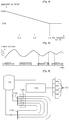
- FIG. 5 is a graph illustrating a variation of a room temperature according to a method of controlling a heating apparatus according to an embodiment of the present invention.
- FIG. 5 if controlling a heating apparatus using the method of controlling a heating apparatus according to the embodiment of the present invention with the above-described structure, upper and lower variations of the room temperature can be reduced.
- a graph having small amplitude is formed on the basis of the room temperature T_ set set by the user.
- FIG. 6 is a schematic diagram illustrating an example of a heating system to which a method of controlling a heating apparatus according to an embodiment of the present invention is applied.
- the heating system includes a heating apparatus 110 that supplies water heated by burning fuel, a heated water distributing unit 120 that distributes the heated water supplied by the heating apparatus 110 into individual rooms, a valve 130 that controls supply and stop of the heated water distributed by the heated water distributing unit 120 to the individual rooms, a valve controller 140 that controls driving of the valve 130, and a room temperature controller 150 that is connected to the valve controller 140 and sets a predetermined room temperature for each of the rooms.
- the valve 130 may be an on/off-typed valve or a proportional control valve that controls the amount of heated water supplied.
- the heating apparatus 110, the valve controller 140, and the room temperature controller 150 are connected to each other through communication lines, and exchange necessary data with each other.
- the valve controller 140 If a current temperature is lower than the room temperature that is set by the room temperature controller 150, the valve controller 140 transmits a signal to the heating apparatus 110, and drives the valve 130 to increase the temperature of a corresponding room.
- a method of controlling the temperature of each room in a district heating system and a central heating system that externally supply heated water also controls overshoot and undershoot using the above-described control method, and can help to provide a comfortable indoor environment for the user.
Description
- The present invention relates to a method of controlling a heating apparatus, and more particularly, to a method of controlling a heating apparatus that is capable of minimizing a difference between a room temperature set by a user and a room temperature measured when the heating apparatus operates.
- Patent document
US 4 ,410,132 discloses relevant prior art. - In general, a heating apparatus means an apparatus that supplies hot water to a heating device. The heating apparatus burns fuel, such as gas, in the heating apparatus, heats water using heat of combustion generated by the burning, and circulates the heated water through piping that is laid in floors of rooms to heat the rooms or supplies hot water using the heated water.
- As a control method that allows a heating apparatus to maintain a room temperature at a temperature set by a user, there are the following methods: a method that measures a room temperature and turns on/off the heating apparatus; a method that measures a temperature of heated water and turns on/off a heating apparatus; and a method that operates a heating apparatus during a period of time set by a user and stops the operation of the heating apparatus during a predetermined period of time.
- The control method that measures the room temperature and turns on/off the heating apparatus is a control method that compares a room temperature measured by a temperature sensor attached to a room temperature controller and a room temperature set by a user and then correspondingly turns on/off a heating apparatus. The process of controlling the heating apparatus using the control method is shown in
FIG. 1 . -
FIG. 1 is a graph illustrating a variation process of a room temperature according to a method of controlling a heating apparatus according to the related art. - First, a user sets a desired room temperature using a room temperature controller that is installed indoor. In this case, the set room temperature becomes T_set, and a heating-off temperature T_off and a heating-on temperature T_ on are respectively set to have predetermined upper and lower temperature ranges on the basis of the room temperature T_set set by the user.
- In this case, the heating-off temperature T_off and the heating-on temperature T_on are values that are input to the room temperature controller in advance. For example, when the user sets the desired room temperature to 25°C, the heating-off temperature T_off may be set to 26°C and the heating-on temperature T_on may be set to 24°C such that upper and lower temperature ranges are maintained within 1°C on the basis of the room temperature of 25°C.
- If the heating apparatus operates, the room temperature increases. At this time, the room temperature is detected by a temperature sensor that is installed in the room temperature controller. If the room temperature detected by the temperature sensor reaches a temperature of 26°C that is the heating-off temperature T_off, it is determined that the temperature reaches the room temperature set by the user, and the operation of the heating apparatus is stopped.
- In this case, since the operation of the heating apparatus is stopped, heat transfer to the heating piping that is laid in the floors of rooms is also stopped, but heat accumulated in the floors of the rooms is continuously radiated to the indoor. As a result, the room temperature increases to a temperature (for example, 27°C) that is higher than the heating-off temperature T_off of 26°C and then decreases. As such, when the room temperature increases to a temperature that is higher than the set heating-off temperature T_off, this is called overshoot.
- When the heating apparatus stops its operation to decrease the room temperature and the room temperature reaches the heating-on temperature of 24°C, the heating apparatus operates again.
- In this case, since the heating apparatus operates, heat is transferred to heating piping that is laid in the floors of the rooms, but a predetermined amount of time is nee ded until the temperature at the floors of the rooms increases to the room temperature set by the user. Thus, the room temperature decreases to a temperature (for example, 23°C) that is lower than the heating-on temperature T_on and then increases again. As such, when the room temperature decreases to a temperature that is lower than the set heating-on temperature T_on, this is called undershoot.
- When the overshoot and undershoot occur as described above, upper and lower variations of the room temperature T_set increase in a temperature range of 23°C to 27°C on the basis of the room temperature T_set of 25°C set by the user, and thus it is not possible to provide a comfortable indoor environment for the user.
- The present invention has been made to solve the above-described problems, and it is an object of the present invention to provide a method of controlling a heating apparatus that is capable of automatically controlling a heating-off temperature T_off and a heating-on temperature T_on according to an operation environment of the heating apparatus such that upper and lower variations of a room temperature set by a user are reduced on the basis of the room temperature, thereby allowing the user to feel comfortable.
- The invention is defined by
independent claim 1. - In order to achieve the above-described object, according to an aspect of the present invention, there is provided a method of controlling a heating apparatus. In this case, a temperature when the heating apparatus is operated to increase the room temperature and the operation of the heating apparatus is stopped is set as a temperature that is obtained by subtracting a heating-off temperature at a cycle immediately before a current cycle by a compensation value determined according to overshoot that has occurred at the cycle immediately before the current cycle, and a temperature when the operation of the heating apparatus is stopped to decrease the room temperature and the heating apparatus is operated is set as a temperature that is obtained by adding the heating-on temperature at the cycle immediately before the current cycle and a compensation value determined according to undershoot that has occurred at the cycle immediately before the current cycle, such that a difference between the measured room temperature and the room temperature set by the user is minimized.
- Preferably, in the heating-off temperature, a minimum heating-off temperature is set as a temperature that is a predetermined temperature higher than the room temperature set by the user, and in the heating-on temperature, a maximum heating-on temperature is set as a temperature that is a predetermined temperature lower than the room temperature set by the user.
- When the room temperature is controlled at the minimum heating-off temperature and the overshoot occurs, a control operation may be performed to reduce the amount of heat produced by the heating apparatus. In this case, it is preferable that a control operation be performed to reduce the amount of heat produced by the heating apparatus in proportion to the amount of overshoot.
- As specifically described above, according to the method of controlling a heating apparatus according to the present invention, it is possible to automatically control a heating-off temperature and a heating-on temperature according to an operation environment of the heating apparatus such that upper and lower variations of a room temperature are reduced, thereby providing a comfortable indoor environment for a user who uses the heating apparatus.
-
-
FIG. 1 is a graph illustrating a variation process of a room temperature according to a method of controlling a heating apparatus according to the related art. -
FIG. 2 is a graph illustrating a variation process of a room temperature when a heating apparatus operates according to a method of controlling a heating apparatus according to an embodiment of the present invention. -
FIG. 3 is a flowchart illustrating a method of controlling a heating apparatus according to an embodiment of the present invention. -
FIG. 4 is a graph illustrating a control method that reduces the amount of heat according to an embodiment of the present invention. -
FIG. 5 is a graph illustrating a variation of a room temperature according to a method of controlling a heating apparatus according to an embodiment of the present invention. -
FIG. 6 is a schematic diagram illustrating an example of a heating system to which a method of controlling a heating apparatus according to an embodiment of the present invention is applied. - Hereinafter, the structure and function of the preferred embodiments of the present invention will be described in detail with reference to the accompanying drawings.
-
FIG. 2 is a graph illustrating a variation process of a room temperature when a heating apparatus operates according to a method of controlling a heating apparatus according to an embodiment of the present invention.FIG. 3 is a flowchart illustrating a method of controlling a heating apparatus according to an embodiment of the present invention. - The present invention relates to implementing a method of controlling a heating apparatus that, when the heating apparatus is turned on/off according to a compared result that is obtained by comparing a room temperature measured by a temperature sensor installed in a room temperature controller and a room temperature set by a user, enables heating to be maintained such that there is a minimal temperature difference on the basis of the room temperature set by the user.
- First, a user sets a desired room temperature using a room temperature controller installed indoor (S101). The set room temperature is represented as T_set in
FIG. 2 , and may become, for example, 25°C. - If the room temperature T_set is set by the user, first, a first heating-off temperature T_off1 and a first heating-on temperature T_on1 are respectively set to have predetermined upper and lower temperature ranges on the basis of the room temperature T_set (S103). For example, the first heating-off temperature T_off1 may become 25.5°C and the first heating-on temperature T_on1 may become 24.5°C.
- If the user sets the room temperature and the heating apparatus operates, the room temperature increases. The heating apparatus continuously operates until the room temperature reaches the first heating-off temperature T_off1 (S105).
- If the heating apparatus operates and the room temperature reaches the first heating-off temperature T_off1 (S107), the operation of the heating apparatus is stopped (S109).
- Here, even though the operation of the heating apparatus is stopped, a large amount of heat that is supplied when the heating apparatus is operated is accumulated in the floors of rooms. As a result, heat is continuously radiated from the floors to the inside of the rooms, which causes overshoot to occur, in which the room temperature increases to a temperature higher than the first heating-off temperature T_off1.
- At this time, the temperature sensor measures a maximum temperature T_max1 of the room temperature that increases due to overshoot, and a control unit computes a difference between the maximum temperature T_max1 and the first heating-off temperature T_off1, that is, the amount of overshoot, and defines a computed value as A 1.
- A compensation value is determined according to the overshoot that has occurred at the first cycle, and a heating-off temperature T_off2 at a next cycle is determined using the determined compensation value.


- That is, the compensation value that is determined according to the overshoot that has occurred at the first cycle is defined as (A1/2), and a value that is obtained by subtracting the first heating-off temperature T_off1 by the compensation value is defined as a heating-off temperature at a next cycle. In this case, a compensation value may be defined as having various values, such as (A1/2) or (A1/3).
- If the operation of the heating apparatus is stopped, the room temperature decreases. If the room temperature reaches the first heating-on temperature T_on1 (S111), the heating apparatus operates again (S113).
- In this case, the room temperature does not immediately increase due to specific heat of indoor air but becomes lower than the first heating-on temperature T_on1, which causes undershoot. At this time, the temperature sensor measures a minimum temperature T_min1 of the room temperature that decreases due to the undershoot, and the control unit computes a difference between the minimum temperature T_min1 and the first heating-on temperature T_on1, that is, the amount of undershoot, and defines a computed value as B1.
- A compensation value is determined according to undershoot that has occurred at the first cycle, and a heating-on temperature T_on2 at a next cycle is determined using the determined compensation value.


- That is, the compensation value that is determined according to the undershoot that has occurred at the first cycle is defined as B1/2, and a value that is obtained by adding the first heating-on temperature T_on1 and the compensation value is defined as a heating-on temperature at a next cycle. In this case, the compensation value may be defined as having various values, such as B1/2 or B1/3.
- The heating apparatus operates and the room temperature increases again. In this case, if the temperature sensor detects that the room temperature reaches the heating-off temperature (that is, T_off2 determined in Equation 1) at the second cycle, the operation of the heating apparatus is stopped (S115 and S117).
- As such, the operation of the heating apparatus is stopped at the temperature that is obtained by subtracting the first heating-off temperature by the compensation value A1/ 2 determined according to the amount of overshoot A1 that has occurred at the first cycle. Thus, a maximum temperature T_max2 of the room temperature becomes lower at the second cycle. Accordingly, it is possible to resolve the problem according to the related art in that a variation in room temperature is large.
- At this time, the temperature sensor measures the maximum temperature T_max2 of the room temperature that increases due to overshoot at the second cycle, and the control unit computes a difference between the maximum temperature T_max2 and the second heating-off temperature T_off2, that is, the amount of overshoot, and defines a computed value as A2.
- A compensation value A2/2 is determined according to the overshoot that has occurred at the second cycle, and a heating-off temperature T_off3 at a next cycle is determined using the determined compensation value.


- As the operation of the heating apparatus is stopped, the room temperature decreases. In this case, if the room temperature reaches the second heating-on temperature T_on2, the heating apparatus operates again (S119 and S121).
- At this time, the temperature sensor measures a minimum temperature T_min2 of the room temperature that decreases due to the undershoot at the second cycle, and the control unit computes a difference between the minimum temperature T_ and the second heating-on temperature T_on2, that is, the amount of undershoot, and defines a computed value as B2.
- A compensation value B2/2 is determined according to the undershoot that has occurred at the second cycle, and a heating-on temperature T_on3 at a next cycle is determined using the compensation value.


- If the above-described method is used to determine the heating-off temperature T_off and the heating-on temperature T_on and the start/stop operation of the heating apparatus is repeated, it is possible to reduce a difference between the room temperature T_set set by the user and the room temperature measured by the temperature sensor. As a result, it is possible to provide a comfortable indoor environment for the user.
- Further, the amounts of overshoot and undershoot that occur when the heating apparatus operates depend on an installation environment of the heating apparatus. Thus, it is difficult to accurately predict the amounts of overshoot and undershoot at the time of designing the heating apparatus. Accordingly, if using the compensation values that are determined according to the amounts of overshoot and undershoot measured by using the above-described method, it becomes possible to automatically set the heating-off temperature T_off and the heating-on temperature T_on, which reduce a variation in the room temperature.
- When the control operation is performed according to the above-described method,
Equations 1 to 8 that compute the heating-off temperature and the heating-on temperature may be represented by the following general Equations.


- In this case, (n) indicates a value at a current controlled cycle, and (n-1) indicates a value determined at a cycle immediately before the current controlled cycle.
- Meanwhile, in order to control the heating-off temperature and the heating-on temperature without error, the heating-off temperature needs to be controlled to be higher than the room temperature T_set set by the user, and the heating-on temperature needs to be controlled to be lower than the room temperature T_set set by the user.
- Accordingly, the heating-off temperature is preferably controlled to be higher than the minimum heating-off temperature T_off_min that is higher than the room temperature T_set set by the user by a predetermined temperature. For example, when the room temperature T_set set by the user is 25°C, the minimum heating-off temperature T_off_min may be defined as 25.2°C.
- The heating-on temperature is preferably controlled to be lower than the maximum heating-on temperature T_on_max that is lower than the room temperature T_set set by the user by a predetermined temperature. For example, when the room temperature T_set set by the user is 25°C, the maximum heating-on temperature T_on_max may be defined as 24.8°C.
-
FIG. 4 is a graph illustrating a control method that reduces the amount of heat according to an embodiment of the present invention. - Even when temperature control is performed such that the room temperature is maintained at the minimum heating-off temperature T_off_min, if overshoot occurs, it is possible to reduce a temperature variation by reducing the amount of heat produced by the heating apparatus.
- That is, when it is determined that the heating-off temperature T_off is continuously decreased to the minimum heating-off temperature T_off_min and overshoot occurs even at the minimum heating-off temperature T_off_min, the control unit controls a gas valve (not shown in the drawings) that controls the amount of gas supplied and reduces the pressure of gas supplied (that is, reduces the amount of heat), thereby preventing overshoot from occurring.
- In this case, in regards to a decreasing rate of the amount of heat, the amount of heat may be decreased in proportion to the amount of overshoot, as shown in
FIG. 4 . That is, when the overshoot does not occur, the amount of heat is controlled to become 100%, and when the overshoot ratio exceeds a predetermined ratio, the amount of heat is controlled to become 50%. Here, the overshoot ratio may be defined as A/(T_off - T_ set). -
FIG. 5 is a graph illustrating a variation of a room temperature according to a method of controlling a heating apparatus according to an embodiment of the present invention. - As shown in
FIG. 5 , if controlling a heating apparatus using the method of controlling a heating apparatus according to the embodiment of the present invention with the above-described structure, upper and lower variations of the room temperature can be reduced. A graph having small amplitude is formed on the basis of the room temperature T_set set by the user. -
FIG. 6 is a schematic diagram illustrating an example of a heating system to which a method of controlling a heating apparatus according to an embodiment of the present invention is applied. - The heating system includes a
heating apparatus 110 that supplies water heated by burning fuel, a heatedwater distributing unit 120 that distributes the heated water supplied by theheating apparatus 110 into individual rooms, avalve 130 that controls supply and stop of the heated water distributed by the heatedwater distributing unit 120 to the individual rooms, avalve controller 140 that controls driving of thevalve 130, and aroom temperature controller 150 that is connected to thevalve controller 140 and sets a predetermined room temperature for each of the rooms. - The
valve 130 may be an on/off-typed valve or a proportional control valve that controls the amount of heated water supplied. - The
heating apparatus 110, thevalve controller 140, and theroom temperature controller 150 are connected to each other through communication lines, and exchange necessary data with each other. - If a current temperature is lower than the room temperature that is set by the
room temperature controller 150, thevalve controller 140 transmits a signal to theheating apparatus 110, and drives thevalve 130 to increase the temperature of a corresponding room. - In this case, a method of controlling overshoot and undershoot that occur due to an increase and a decrease in the room temperature is the same as the above-described control method.
- A method of controlling the temperature of each room in a district heating system and a central heating system that externally supply heated water also controls overshoot and undershoot using the above-described control method, and can help to provide a comfortable indoor environment for the user.
- It will be apparent to those skilled in the art that various modifications and changes may be made without departing from the present invention. Therefore, it should be understood that the above embodiments are not limitative, but illustrative in all aspects.
Claims (3)
- A method of controlling a heating apparatus (110) that controls the start/stop operation of the heating apparatus (110) on the basis of a room tem-perature (T_set) set by a user,
wherein for a given cycle a heating-off temperature, at which the operation of the heating apparatus (110) is stopped, is set as a temperature that is obtained by subtracting a compensation value determined according to the temperature overshoot (A) that has occurred in the cycle immediately preceding the current cycle from the heating-off temperature from the said preceding cycle,
wherein for a given cycle a heating-on temperature, at which the operation of the heating apparatus is started, is set as a temperature that is obtained by adding a compensation value determined according to the temperature undershoot that has occurred in the cycle immediately preceding the current cycle to the heating-on temperature from the said preceding cycle,
whereby a difference between the measured room temperature (T_set) and the room temperature set by the user is minimized, characterized in thati) a minimum heating-off temperature (T_off_min) is set as a temperature that is a predetermined temperature higher than the room temperature (T_set) set by the user, whereby the heating-off temperature that is compensated by the compensa-tion value determined according to overshoot (A) is controlled not to be less than the minimum heating-off temperature (T_off_min) andii) a maximum heating-on temperature (T_on_max) is set as a temperature that is a predetermined temperature lower than the room temperature (T_set) set by the user, whereby the heating-on temperature that is compensated by the compensation value determined according to undershoot (B) is controlled not to be higher than the maximum-on temperature (T_on_max). - The method of claim 1 wherein, when the room temperature (T_set) is controlled at the minimum heating-off temperature (T_off_min) and the overshoot (A) occurs, a control operation is performed to reduce the amount of heat produced by the heating apparatus (110).
- The method of claim 2, wherein, when the room temperature (T_set) is controlled at the minimum heating-off temperature (T_off_min) and the overshoot (A) occurs, a control operation is performed to reduce the amount of heat produced by the heating apparatus (110) in proportion to the amount of overshoot (A).
Applications Claiming Priority (2)
| Application Number | Priority Date | Filing Date | Title |
|---|---|---|---|
| KR1020070025403A KR100820650B1 (en) | 2007-03-15 | 2007-03-15 | Method for controlling heating apparatus |
| PCT/KR2008/001344 WO2008111780A1 (en) | 2007-03-15 | 2008-03-10 | Method for controlling heating apparatus |
Publications (3)
| Publication Number | Publication Date |
|---|---|
| EP2129971A1 EP2129971A1 (en) | 2009-12-09 |
| EP2129971A4 EP2129971A4 (en) | 2014-07-02 |
| EP2129971B1 true EP2129971B1 (en) | 2016-12-21 |
Family
ID=39534267
Family Applications (1)
| Application Number | Title | Priority Date | Filing Date |
|---|---|---|---|
| EP08723381.3A Not-in-force EP2129971B1 (en) | 2007-03-15 | 2008-03-10 | Method for controlling heating apparatus |
Country Status (6)
| Country | Link |
|---|---|
| US (1) | US20100096467A1 (en) |
| EP (1) | EP2129971B1 (en) |
| JP (1) | JP5146850B2 (en) |
| KR (1) | KR100820650B1 (en) |
| CN (1) | CN101680665B (en) |
| WO (1) | WO2008111780A1 (en) |
Families Citing this family (14)
| Publication number | Priority date | Publication date | Assignee | Title |
|---|---|---|---|---|
| KR100985384B1 (en) * | 2008-06-27 | 2010-10-05 | 주식회사 경동네트웍 | Method for controlling a hot water temperature in using low flux in hot water supply system |
| CN102252364B (en) * | 2011-04-29 | 2015-03-25 | 江丛兴 | Method for compensating and regulating heating temperature of centralized heat supply network |
| KR20130080737A (en) * | 2012-01-05 | 2013-07-15 | 엘지전자 주식회사 | Air conditioner and home-leave driving method thereof |
| DE102012207305A1 (en) * | 2012-05-02 | 2013-11-07 | Webasto Ag | A heater for a vehicle and method of operating the heater |
| US9279590B2 (en) * | 2012-09-12 | 2016-03-08 | R.W. Beckett Corporation | Warm weather boiler shutdown |
| EP2713233A3 (en) * | 2012-09-26 | 2015-12-09 | Gordon Seiptius | Method for regulating a room temperature, controller for a cooling device and cooling device |
| CN104515194B (en) * | 2013-09-26 | 2017-08-01 | 珠海格力电器股份有限公司 | The control method and device of heating system |
| GB2520293B (en) | 2013-11-14 | 2018-02-07 | Passivsystems Ltd | Improvements in and relating to temperature controlled systems |
| CN104833040B (en) * | 2014-02-12 | 2017-09-15 | 珠海格力电器股份有限公司 | The temprature control method and temperature controller of air-conditioning system |
| CN103912914B (en) * | 2014-04-22 | 2016-10-05 | 珠海格力电器股份有限公司 | A kind of control method of floor heating |
| US10697651B2 (en) * | 2015-12-23 | 2020-06-30 | Intel Corporation | Energy efficient combustion heater control |
| CN110553365B (en) * | 2019-09-17 | 2022-04-15 | 广东美的制冷设备有限公司 | Control method of air conditioner, air conditioner and storage medium |
| CN111351227B (en) * | 2020-02-13 | 2021-10-19 | 青岛经济技术开发区海尔热水器有限公司 | Water heater control method with zero cold water circulation function and water heater |
| CN111981547B (en) * | 2020-05-22 | 2022-03-04 | 太原大四方节能环保股份有限公司 | Indoor temperature direct regulation and control device and method for central heating heat exchange station |
Family Cites Families (36)
| Publication number | Priority date | Publication date | Assignee | Title |
|---|---|---|---|---|
| US3248896A (en) * | 1964-10-16 | 1966-05-03 | Westinghouse Electric Corp | Controls for centrifugal refrigerant compressors having spin vanes in their inlets |
| US3465961A (en) * | 1967-07-14 | 1969-09-09 | Texas Instruments Inc | Temperature control apparatus |
| US4420677A (en) * | 1979-08-06 | 1983-12-13 | Partington Everett J | Heating system |
| US4410132A (en) * | 1980-11-14 | 1983-10-18 | Levine Michael R | Thermostat with dead zone seeking servo action |
| DE3517954A1 (en) * | 1985-05-18 | 1986-11-20 | Webasto-Werk W. Baier GmbH & Co, 8035 Gauting | HEATER |
| JPS62123511A (en) | 1985-11-22 | 1987-06-04 | Toto Ltd | Hot and cold water mixing valve device |
| JPH0613247B2 (en) * | 1986-04-02 | 1994-02-23 | 株式会社日立製作所 | Control device for automobile air conditioner |
| US4897798A (en) * | 1986-12-08 | 1990-01-30 | American Telephone And Telegraph Company | Adaptive environment control system |
| JPS63180036A (en) * | 1987-01-20 | 1988-07-25 | Mitsubishi Electric Corp | Room temperature controller |
| US4913038A (en) * | 1988-08-03 | 1990-04-03 | Henny Penny Corporation | Deep fat fryer with computerized control system |
| JPH0277813A (en) * | 1988-09-13 | 1990-03-16 | Toto Ltd | Hot water and cold water mixing device |
| JPH02156829A (en) * | 1988-12-09 | 1990-06-15 | Nepon Kk | Method for setting temperature with room-temperature thermostat |
| JPH04121521A (en) * | 1990-09-12 | 1992-04-22 | Toshiba Heating Appliances Co | Heating controller of heater |
| US5245835A (en) * | 1992-08-10 | 1993-09-21 | Electric Power Research Institute, Inc. | Method and apparatus for interior space conditioning with improved zone control |
| JP3129050B2 (en) * | 1993-08-18 | 2001-01-29 | 株式会社ノーリツ | Room temperature adjustment control method |
| JP3206245B2 (en) * | 1993-08-30 | 2001-09-10 | 株式会社ノーリツ | Air conditioner |
| CA2144201C (en) * | 1994-03-17 | 1999-05-25 | Charles A. Maher, Jr. | Electronic control system for a heating apparatus |
| FR2743025B1 (en) * | 1995-12-27 | 1998-02-13 | Valeo Climatisation | ELECTRONIC CONTROL DEVICE FOR HEATING, VENTILATION AND / OR AIR CONDITIONING INSTALLATION OF A MOTOR VEHICLE |
| JPH1038286A (en) | 1996-07-26 | 1998-02-13 | Mitsubishi Electric Corp | Hot-water heater |
| US6467537B1 (en) * | 2000-05-17 | 2002-10-22 | Carrier Corporation | Advanced starting control for multiple zone system |
| US6453993B1 (en) * | 2000-05-17 | 2002-09-24 | Carrier Corporation | Advanced starting control for multiple zone system |
| US6409090B1 (en) * | 2000-05-18 | 2002-06-25 | Microtherm Llc | Self-optimizing device for controlling a heating system |
| US20040104278A1 (en) * | 2002-11-22 | 2004-06-03 | Walsh Paul J. | System and apparatus for refrigeration and heating |
| US6834714B2 (en) * | 2002-11-22 | 2004-12-28 | Paul J. Walsh | Variable constant volume cooling/heating unit |
| CN2684058Y (en) * | 2003-10-23 | 2005-03-09 | 郝勇 | Intelligent temperature control type energy-saving warmer |
| CN1236237C (en) * | 2003-11-03 | 2006-01-11 | 赵永刚 | Intellectualized heating management system for each family |
| US6940047B2 (en) * | 2003-11-14 | 2005-09-06 | Asm International N.V. | Heat treatment apparatus with temperature control system |
| US7025280B2 (en) * | 2004-01-30 | 2006-04-11 | Tokyo Electron Limited | Adaptive real time control of a reticle/mask system |
| TWI248863B (en) * | 2004-02-12 | 2006-02-11 | Mitsubishi Heavy Ind Ltd | Apparatus and method for mold temperature adjustment, and mold temperature control unit |
| US7100597B2 (en) * | 2004-05-25 | 2006-09-05 | Rand Tyler B | Modular burner/blower system and method |
| US7168627B2 (en) * | 2004-10-06 | 2007-01-30 | Lawrence Kates | Electronically-controlled register vent for zone heating and cooling |
| US7156316B2 (en) * | 2004-10-06 | 2007-01-02 | Lawrence Kates | Zone thermostat for zone heating and cooling |
| US7163156B2 (en) * | 2004-10-06 | 2007-01-16 | Lawrence Kates | System and method for zone heating and cooling |
| JP4121521B2 (en) * | 2005-09-27 | 2008-07-23 | 高階救命器具株式会社 | Life preserver |
| US7644869B2 (en) * | 2005-12-28 | 2010-01-12 | Honeywell International Inc. | Auxiliary stage control of multistage thermostats |
| JP5254559B2 (en) * | 2007-02-23 | 2013-08-07 | 三菱重工業株式会社 | Air conditioning apparatus and automatic heating operation control method |
-
2007
- 2007-03-15 KR KR1020070025403A patent/KR100820650B1/en active IP Right Grant
-
2008
- 2008-03-10 CN CN2008800084616A patent/CN101680665B/en not_active Expired - Fee Related
- 2008-03-10 WO PCT/KR2008/001344 patent/WO2008111780A1/en active Application Filing
- 2008-03-10 JP JP2009553515A patent/JP5146850B2/en not_active Expired - Fee Related
- 2008-03-10 US US12/531,060 patent/US20100096467A1/en not_active Abandoned
- 2008-03-10 EP EP08723381.3A patent/EP2129971B1/en not_active Not-in-force
Non-Patent Citations (1)
| Title |
|---|
| None * |
Also Published As
| Publication number | Publication date |
|---|---|
| JP5146850B2 (en) | 2013-02-20 |
| WO2008111780A1 (en) | 2008-09-18 |
| CN101680665B (en) | 2012-04-25 |
| US20100096467A1 (en) | 2010-04-22 |
| EP2129971A4 (en) | 2014-07-02 |
| CN101680665A (en) | 2010-03-24 |
| EP2129971A1 (en) | 2009-12-09 |
| JP2010521647A (en) | 2010-06-24 |
| KR100820650B1 (en) | 2008-04-08 |
Similar Documents
| Publication | Publication Date | Title |
|---|---|---|
| EP2129971B1 (en) | Method for controlling heating apparatus | |
| CN104296386B (en) | Control method, control system and the gas heater of gas heater | |
| US20110000973A1 (en) | Device for control room temperature of each room adapted to heating environment and its method | |
| KR100905924B1 (en) | Device for control each temperature of warm circulation water of each room control system | |
| CN108474587B (en) | Boiler for heating and water heating and control method thereof | |
| KR101435902B1 (en) | Heating Control System Capable of Controlling Temperature on the basis of Heating Load and Temperature Control Method thereof | |
| CN107003013B (en) | Heater control method of water heating pad and water heating pad suitable for heater control method | |
| CN100589056C (en) | Method of controlling temperature of warm water of bidet | |
| KR20140144497A (en) | Method for controlling heating of boiler and apparatus thereof | |
| CN114017929B (en) | Control method of gas water heater, device and storage medium | |
| KR101190437B1 (en) | Automatic valve position measuring apparatus by using education effect for each room in each heating system | |
| US8381689B2 (en) | Method for examining water heater safety | |
| JP2006329529A (en) | Heat medium circulating type heating apparatus | |
| JP2002039552A (en) | Floor-heating apparatus | |
| JP2013231523A (en) | Air conditioning control device and method | |
| KR100614584B1 (en) | Method for controlling temperature of boiler's domestic hot water | |
| CN108278657B (en) | Constant-pressure constant-temperature control method for wall-mounted boiler heating system | |
| US20230131014A1 (en) | Combustion device | |
| JP4155896B2 (en) | Heat medium supply equipment | |
| KR20100110115A (en) | Heating apparatus with an automatic linkage controller between solar thermal system and boiler and the method thereof | |
| JPH10238853A (en) | One-can two-channel hot water supply machine | |
| JP2024030632A (en) | Connected hot water system | |
| KR101647128B1 (en) | Cascade system for controlling numbers of standby boiler or gas water heater and method of the system | |
| JP2007292383A (en) | Connected hot water supply system | |
| JP2014159888A (en) | Hot water supply system |
Legal Events
| Date | Code | Title | Description |
|---|---|---|---|
| PUAI | Public reference made under article 153(3) epc to a published international application that has entered the european phase |
Free format text: ORIGINAL CODE: 0009012 |
|
| 17P | Request for examination filed |
Effective date: 20090925 |
|
| AK | Designated contracting states |
Kind code of ref document: A1 Designated state(s): AT BE BG CH CY CZ DE DK EE ES FI FR GB GR HR HU IE IS IT LI LT LU LV MC MT NL NO PL PT RO SE SI SK TR |
|
| DAX | Request for extension of the european patent (deleted) | ||
| RAP1 | Party data changed (applicant data changed or rights of an application transferred) |
Owner name: KYUNGDONG ONE CORPORATION |
|
| A4 | Supplementary search report drawn up and despatched |
Effective date: 20140602 |
|
| RIC1 | Information provided on ipc code assigned before grant |
Ipc: G05D 23/19 20060101ALI20140526BHEP Ipc: F24D 19/10 20060101AFI20140526BHEP |
|
| GRAP | Despatch of communication of intention to grant a patent |
Free format text: ORIGINAL CODE: EPIDOSNIGR1 |
|
| INTG | Intention to grant announced |
Effective date: 20160708 |
|
| GRAS | Grant fee paid |
Free format text: ORIGINAL CODE: EPIDOSNIGR3 |
|
| GRAA | (expected) grant |
Free format text: ORIGINAL CODE: 0009210 |
|
| AK | Designated contracting states |
Kind code of ref document: B1 Designated state(s): AT BE BG CH CY CZ DE DK EE ES FI FR GB GR HR HU IE IS IT LI LT LU LV MC MT NL NO PL PT RO SE SI SK TR |
|
| REG | Reference to a national code |
Ref country code: GB Ref legal event code: FG4D |
|
| REG | Reference to a national code |
Ref country code: CH Ref legal event code: EP |
|
| REG | Reference to a national code |
Ref country code: IE Ref legal event code: FG4D |
|
| REG | Reference to a national code |
Ref country code: CH Ref legal event code: NV Representative=s name: REUTELER AND CIE S.A., CH |
|
| REG | Reference to a national code |
Ref country code: AT Ref legal event code: REF Ref document number: 855837 Country of ref document: AT Kind code of ref document: T Effective date: 20170115 |
|
| REG | Reference to a national code |
Ref country code: DE Ref legal event code: R096 Ref document number: 602008047981 Country of ref document: DE |
|
| PG25 | Lapsed in a contracting state [announced via postgrant information from national office to epo] |
Ref country code: LV Free format text: LAPSE BECAUSE OF FAILURE TO SUBMIT A TRANSLATION OF THE DESCRIPTION OR TO PAY THE FEE WITHIN THE PRESCRIBED TIME-LIMIT Effective date: 20161221 |
|
| REG | Reference to a national code |
Ref country code: NL Ref legal event code: FP |
|
| REG | Reference to a national code |
Ref country code: LT Ref legal event code: MG4D |
|
| PG25 | Lapsed in a contracting state [announced via postgrant information from national office to epo] |
Ref country code: GR Free format text: LAPSE BECAUSE OF FAILURE TO SUBMIT A TRANSLATION OF THE DESCRIPTION OR TO PAY THE FEE WITHIN THE PRESCRIBED TIME-LIMIT Effective date: 20170322 Ref country code: SE Free format text: LAPSE BECAUSE OF FAILURE TO SUBMIT A TRANSLATION OF THE DESCRIPTION OR TO PAY THE FEE WITHIN THE PRESCRIBED TIME-LIMIT Effective date: 20161221 Ref country code: LT Free format text: LAPSE BECAUSE OF FAILURE TO SUBMIT A TRANSLATION OF THE DESCRIPTION OR TO PAY THE FEE WITHIN THE PRESCRIBED TIME-LIMIT Effective date: 20161221 Ref country code: NO Free format text: LAPSE BECAUSE OF FAILURE TO SUBMIT A TRANSLATION OF THE DESCRIPTION OR TO PAY THE FEE WITHIN THE PRESCRIBED TIME-LIMIT Effective date: 20170321 |
|
| REG | Reference to a national code |
Ref country code: AT Ref legal event code: MK05 Ref document number: 855837 Country of ref document: AT Kind code of ref document: T Effective date: 20161221 |
|
| PG25 | Lapsed in a contracting state [announced via postgrant information from national office to epo] |
Ref country code: FI Free format text: LAPSE BECAUSE OF FAILURE TO SUBMIT A TRANSLATION OF THE DESCRIPTION OR TO PAY THE FEE WITHIN THE PRESCRIBED TIME-LIMIT Effective date: 20161221 Ref country code: HR Free format text: LAPSE BECAUSE OF FAILURE TO SUBMIT A TRANSLATION OF THE DESCRIPTION OR TO PAY THE FEE WITHIN THE PRESCRIBED TIME-LIMIT Effective date: 20161221 |
|
| PG25 | Lapsed in a contracting state [announced via postgrant information from national office to epo] |
Ref country code: RO Free format text: LAPSE BECAUSE OF FAILURE TO SUBMIT A TRANSLATION OF THE DESCRIPTION OR TO PAY THE FEE WITHIN THE PRESCRIBED TIME-LIMIT Effective date: 20161221 Ref country code: EE Free format text: LAPSE BECAUSE OF FAILURE TO SUBMIT A TRANSLATION OF THE DESCRIPTION OR TO PAY THE FEE WITHIN THE PRESCRIBED TIME-LIMIT Effective date: 20161221 Ref country code: SK Free format text: LAPSE BECAUSE OF FAILURE TO SUBMIT A TRANSLATION OF THE DESCRIPTION OR TO PAY THE FEE WITHIN THE PRESCRIBED TIME-LIMIT Effective date: 20161221 Ref country code: IS Free format text: LAPSE BECAUSE OF FAILURE TO SUBMIT A TRANSLATION OF THE DESCRIPTION OR TO PAY THE FEE WITHIN THE PRESCRIBED TIME-LIMIT Effective date: 20170421 |
|
| PG25 | Lapsed in a contracting state [announced via postgrant information from national office to epo] |
Ref country code: BG Free format text: LAPSE BECAUSE OF FAILURE TO SUBMIT A TRANSLATION OF THE DESCRIPTION OR TO PAY THE FEE WITHIN THE PRESCRIBED TIME-LIMIT Effective date: 20170321 Ref country code: AT Free format text: LAPSE BECAUSE OF FAILURE TO SUBMIT A TRANSLATION OF THE DESCRIPTION OR TO PAY THE FEE WITHIN THE PRESCRIBED TIME-LIMIT Effective date: 20161221 Ref country code: PL Free format text: LAPSE BECAUSE OF FAILURE TO SUBMIT A TRANSLATION OF THE DESCRIPTION OR TO PAY THE FEE WITHIN THE PRESCRIBED TIME-LIMIT Effective date: 20161221 Ref country code: ES Free format text: LAPSE BECAUSE OF FAILURE TO SUBMIT A TRANSLATION OF THE DESCRIPTION OR TO PAY THE FEE WITHIN THE PRESCRIBED TIME-LIMIT Effective date: 20161221 Ref country code: PT Free format text: LAPSE BECAUSE OF FAILURE TO SUBMIT A TRANSLATION OF THE DESCRIPTION OR TO PAY THE FEE WITHIN THE PRESCRIBED TIME-LIMIT Effective date: 20170421 Ref country code: BE Free format text: LAPSE BECAUSE OF FAILURE TO SUBMIT A TRANSLATION OF THE DESCRIPTION OR TO PAY THE FEE WITHIN THE PRESCRIBED TIME-LIMIT Effective date: 20161221 |
|
| REG | Reference to a national code |
Ref country code: DE Ref legal event code: R097 Ref document number: 602008047981 Country of ref document: DE |
|
| PLBE | No opposition filed within time limit |
Free format text: ORIGINAL CODE: 0009261 |
|
| STAA | Information on the status of an ep patent application or granted ep patent |
Free format text: STATUS: NO OPPOSITION FILED WITHIN TIME LIMIT |
|
| 26N | No opposition filed |
Effective date: 20170922 |
|
| PG25 | Lapsed in a contracting state [announced via postgrant information from national office to epo] |
Ref country code: MC Free format text: LAPSE BECAUSE OF FAILURE TO SUBMIT A TRANSLATION OF THE DESCRIPTION OR TO PAY THE FEE WITHIN THE PRESCRIBED TIME-LIMIT Effective date: 20161221 Ref country code: DK Free format text: LAPSE BECAUSE OF FAILURE TO SUBMIT A TRANSLATION OF THE DESCRIPTION OR TO PAY THE FEE WITHIN THE PRESCRIBED TIME-LIMIT Effective date: 20161221 |
|
| REG | Reference to a national code |
Ref country code: IE Ref legal event code: MM4A |
|
| REG | Reference to a national code |
Ref country code: FR Ref legal event code: ST Effective date: 20171130 |
|
| PG25 | Lapsed in a contracting state [announced via postgrant information from national office to epo] |
Ref country code: FR Free format text: LAPSE BECAUSE OF NON-PAYMENT OF DUE FEES Effective date: 20170331 Ref country code: LU Free format text: LAPSE BECAUSE OF NON-PAYMENT OF DUE FEES Effective date: 20170310 |
|
| PG25 | Lapsed in a contracting state [announced via postgrant information from national office to epo] |
Ref country code: IE Free format text: LAPSE BECAUSE OF NON-PAYMENT OF DUE FEES Effective date: 20170310 Ref country code: SI Free format text: LAPSE BECAUSE OF FAILURE TO SUBMIT A TRANSLATION OF THE DESCRIPTION OR TO PAY THE FEE WITHIN THE PRESCRIBED TIME-LIMIT Effective date: 20161221 |
|
| PG25 | Lapsed in a contracting state [announced via postgrant information from national office to epo] |
Ref country code: MT Free format text: LAPSE BECAUSE OF NON-PAYMENT OF DUE FEES Effective date: 20170310 |
|
| REG | Reference to a national code |
Ref country code: CH Ref legal event code: NV Representative=s name: SCHNEIDER FELDMANN AG PATENT- UND MARKENANWAEL, CH Ref country code: CH Ref legal event code: PUE Owner name: KYUNGDONG ELECTRONICS CO., LTD., KR Free format text: FORMER OWNER: KYUNGDONG ONE CORPORATION, KR |
|
| PGFP | Annual fee paid to national office [announced via postgrant information from national office to epo] |
Ref country code: GB Payment date: 20190306 Year of fee payment: 12 Ref country code: CZ Payment date: 20190219 Year of fee payment: 12 Ref country code: CH Payment date: 20190314 Year of fee payment: 12 Ref country code: DE Payment date: 20190226 Year of fee payment: 12 Ref country code: IT Payment date: 20190326 Year of fee payment: 12 |
|
| PGFP | Annual fee paid to national office [announced via postgrant information from national office to epo] |
Ref country code: TR Payment date: 20190306 Year of fee payment: 12 Ref country code: NL Payment date: 20190313 Year of fee payment: 12 |
|
| PG25 | Lapsed in a contracting state [announced via postgrant information from national office to epo] |
Ref country code: HU Free format text: LAPSE BECAUSE OF FAILURE TO SUBMIT A TRANSLATION OF THE DESCRIPTION OR TO PAY THE FEE WITHIN THE PRESCRIBED TIME-LIMIT; INVALID AB INITIO Effective date: 20080310 |
|
| REG | Reference to a national code |
Ref country code: NL Ref legal event code: PD Owner name: KYUNGDONG ELECTRONICS CO., LTD.; KR Free format text: DETAILS ASSIGNMENT: CHANGE OF OWNER(S), DEMERGER; FORMER OWNER NAME: KYUNGDONG ONE CORPORATION Effective date: 20190715 |
|
| REG | Reference to a national code |
Ref country code: DE Ref legal event code: R082 Ref document number: 602008047981 Country of ref document: DE Representative=s name: FUCHS PATENTANWAELTE PARTNERSCHAFT MBB, DE Ref country code: DE Ref legal event code: R081 Ref document number: 602008047981 Country of ref document: DE Owner name: KYUNGDONG ELECTRONICS CO., LTD., KR Free format text: FORMER OWNER: KYUNGDONG ONE CORP., SEOUL, KR |
|
| PG25 | Lapsed in a contracting state [announced via postgrant information from national office to epo] |
Ref country code: CY Free format text: LAPSE BECAUSE OF NON-PAYMENT OF DUE FEES Effective date: 20161221 |
|
| REG | Reference to a national code |
Ref country code: DE Ref legal event code: R119 Ref document number: 602008047981 Country of ref document: DE |
|
| REG | Reference to a national code |
Ref country code: CH Ref legal event code: PFA Owner name: KYUNGDONG ELECTRONICS CO., LTD., KR Free format text: FORMER OWNER: KYUNGDONG ELECTRONICS CO., LTD., KR |
|
| PG25 | Lapsed in a contracting state [announced via postgrant information from national office to epo] |
Ref country code: CZ Free format text: LAPSE BECAUSE OF NON-PAYMENT OF DUE FEES Effective date: 20200310 |
|
| REG | Reference to a national code |
Ref country code: CH Ref legal event code: PL |
|
| REG | Reference to a national code |
Ref country code: NL Ref legal event code: MM Effective date: 20200401 |
|
| PG25 | Lapsed in a contracting state [announced via postgrant information from national office to epo] |
Ref country code: NL Free format text: LAPSE BECAUSE OF NON-PAYMENT OF DUE FEES Effective date: 20200401 |
|
| PG25 | Lapsed in a contracting state [announced via postgrant information from national office to epo] |
Ref country code: CH Free format text: LAPSE BECAUSE OF NON-PAYMENT OF DUE FEES Effective date: 20200331 Ref country code: LI Free format text: LAPSE BECAUSE OF NON-PAYMENT OF DUE FEES Effective date: 20200331 Ref country code: DE Free format text: LAPSE BECAUSE OF NON-PAYMENT OF DUE FEES Effective date: 20201001 |
|
| GBPC | Gb: european patent ceased through non-payment of renewal fee |
Effective date: 20200310 |
|
| PG25 | Lapsed in a contracting state [announced via postgrant information from national office to epo] |
Ref country code: GB Free format text: LAPSE BECAUSE OF NON-PAYMENT OF DUE FEES Effective date: 20200310 |
|
| PG25 | Lapsed in a contracting state [announced via postgrant information from national office to epo] |
Ref country code: IT Free format text: LAPSE BECAUSE OF NON-PAYMENT OF DUE FEES Effective date: 20200310 |
|
| PG25 | Lapsed in a contracting state [announced via postgrant information from national office to epo] |
Ref country code: TR Free format text: LAPSE BECAUSE OF NON-PAYMENT OF DUE FEES Effective date: 20200310 |