EP2129227B1 - Net rucking apparatus and method - Google Patents
Net rucking apparatus and method Download PDFInfo
- Publication number
- EP2129227B1 EP2129227B1 EP08744068.1A EP08744068A EP2129227B1 EP 2129227 B1 EP2129227 B1 EP 2129227B1 EP 08744068 A EP08744068 A EP 08744068A EP 2129227 B1 EP2129227 B1 EP 2129227B1
- Authority
- EP
- European Patent Office
- Prior art keywords
- tube
- netting
- ring
- frustum
- frusto
- Prior art date
- Legal status (The legal status is an assumption and is not a legal conclusion. Google has not performed a legal analysis and makes no representation as to the accuracy of the status listed.)
- Not-in-force
Links
Images


Classifications
-
- A—HUMAN NECESSITIES
- A22—BUTCHERING; MEAT TREATMENT; PROCESSING POULTRY OR FISH
- A22C—PROCESSING MEAT, POULTRY, OR FISH
- A22C11/00—Sausage making ; Apparatus for handling or conveying sausage products during manufacture
- A22C11/001—Machines for making skinless sausages, e.g. Frankfurters, Wieners
- A22C11/005—Apparatus for binding or tying sausages or meat, e.g. salami, rollades; Filling sausage products into sleeve netting
-
- A—HUMAN NECESSITIES
- A22—BUTCHERING; MEAT TREATMENT; PROCESSING POULTRY OR FISH
- A22C—PROCESSING MEAT, POULTRY, OR FISH
- A22C13/00—Sausage casings
- A22C13/02—Shirring of sausage casings
-
- B—PERFORMING OPERATIONS; TRANSPORTING
- B65—CONVEYING; PACKING; STORING; HANDLING THIN OR FILAMENTARY MATERIAL
- B65B—MACHINES, APPARATUS OR DEVICES FOR, OR METHODS OF, PACKAGING ARTICLES OR MATERIALS; UNPACKING
- B65B9/00—Enclosing successive articles, or quantities of material, e.g. liquids or semiliquids, in flat, folded, or tubular webs of flexible sheet material; Subdividing filled flexible tubes to form packages
- B65B9/10—Enclosing successive articles, or quantities of material, in preformed tubular webs, or in webs formed into tubes around filling nozzles, e.g. extruded tubular webs
- B65B9/15—Enclosing successive articles, or quantities of material, in preformed tubular webs, or in webs formed into tubes around filling nozzles, e.g. extruded tubular webs the preformed tubular webs being stored on filling nozzles
Definitions
- This invention relates to the field of preparing food products in shirred, tubular casings and enclosing the products in netting.
- One method generally used in the industry is to pump food products, such as sausage meat, whole muscle meats, or otherwise, through a product horn.
- the meat products are forced into an edible film and then into netting.
- the food products to be packaged will expand and push the film through the netting.
- After processing, such as smoking or cooking the netting will be removed, leaving a dimpled appearance on the food products that is considered pleasing to consumers.
- the edible casing will prevent the netting from sticking to the meat, so upon removal of the netting a clean appearance of the meat is maintained.
- the tubular netting used in this process arrives from the manufacturers in a flattened state and wrapped circumferentially on a disposable cylinder.
- the netting has to be shirred onto a temporary netting tube.
- This shirring process, or "rucking" involves placing the netting coaxially onto the netting tube.
- the tube is placed on a sausage making machine for extrusion of sausage, as described in the '034 and '477 patents and as illustrated in, for example, FIG. 7 of those patents.
- the netting tube is caused to reciprocate vertically, such as by use of an air cylinder.
- the netting is stretched over the tube.
- a plurality of spring-loaded fingers secured to a bracket surround the netting tube circumferentially. These fingers are normally in a horizontal position. Downward force moves them down; the springs cause them to snap back to the normal horizontal position when the force is removed. Accordingly, the fingers carry the netting downward during the upward stroke of the tube, and slide over the netting during the downward stroke of the tube.
- the reciprocating motion of the netting tube therefore causes the netting to be shirred onto the netting tube.
- This prior art is described in, for example, U.S. Patent No. 5,273,481 to Sullivan , Net Rucker . Note that only one layer of netting is shirred onto the netting tube by this method.
- a prior art improvement is to add a second tube, which fits coaxially over the netting tube.
- the netting is stretched over the second tube.
- the second tube rises in relation to the netting tube and the netting is shirred onto the netting tube, in the space between the base of the netting tube and the now-rising second tube.
- More netting can be shirred onto the netting tube in this manner, as compared to the prior art method of the previous paragraph, because multiple layers can be shirred, thereby rucking more linear feet of netting per length of netting tube.
- the netting is not shirred particularly neatly by this method. It bunches up and is wavy.
- This prior art improvement used a second tube with a larger inside diameter than the outside diameter of the netting tube. Accordingly, a tube cap is inserted into the top of the second tube, to keep the second tube moving coaxially to the netting tube, and to allow the netting to slide smoothly over the second tube. A coaxial ring in the bottom of the second tube keeps the second tube coaxial to the netting tube, and will push the netting downward on the netting tube.
- the use of a net derucker further increases the need for maximizing the amount of netting that can be rucked onto a netting tube of given length. (Please note that more netting can be rucked onto a netting tube simply by increasing the size of the netting tube, but this option is not available or, at best, is impractical, for users with limited space.)
- an apparatus for rucking netting onto a tube comprises a frame having an axis, a passage along the axis, means for reciprocating movement along the axis, a netting tube releasably attachable to the means for reciprocating movement, a second tube comprising a frustum having a bore, the second tube being slidable co-axially to the netting tube, an annular space defined by the second tube and the netting tube, and spring-loaded fingers attached to the frame and extending into the passage.
- a method for rucking netting onto a tube comprises attaching a netting tube to a moveable platform, mounting a second tube axially over the netting tube, the second tube comprising a frustum having a bore therethrough, placing an end of a netting over the second tube, forming an annular space between the netting tube and the second tube, and moving the second tube reciprocatingly through spring-loaded fingers.
- the second tube comprises a frustum having a bore therethrough, and can be a frusto-conical shape, a frusto-pyramidal shape, or another frustum shape.
- the preferred embodiment of the net rucking apparatus 2 is shown in elevation view in FIG. 1 without the netting 4 present, and in FIG. 1A with netting 4 present.
- the apparatus 2 comprises a frame 10, a netting tube 40, and a second tube 50.
- the frame 10 has legs 12 to support it, and upper arms 14 that hold a net rucker head 16.
- the net rucker head 16 defines a passage 18 through which the netting tube 40 and second tube 50 pass. Attached to the net rucker head 16 and extending into the passage 18 is a plurality of spring-loaded fingers 20.
- a moveable platform 22 sits on top of the frame 10. It is configured to travel in an upward and downward direction, powered by a lifting means.
- the lifting means comprises a reciprocating air-actuated cylinder 24, connected to an air supply 26 which is controlled by a control means 28.
- control means 28 is a microprocessor with an application-specific program written to it.
- a digital or analog controller is used.
- apparatus 2 is controlled manually.
- Netting 4 is placed in a net tray 30 that is attached to an upper arm 14.
- the leading edge of the netting 4 travels up to a net guide 32, attached to and above one of the upper arms 14 and above the net rucker head 16.
- the net guide 32 leads the netting 4 down through the passage 18 as will hereinafter be described.
- Netting tube 40 shown enlarged in FIG. 2 , is a hollow cylinder with a base plate 42.
- netting tube 40 is stainless steel, for use in a food-processing environment.
- attachment means 44 on baseplate 42, to hold netting tube 40 securely to moveable platform 22.
- Attachment means 44 are preferably identical to the means by which netting tube 40 will be attached to a sausage-making machine after rucking of the netting 4.
- Attachment means 44 is preferably a locking clamp.
- attachment means is a nut-and-bolt arrangement, a bayonet attachment, a threading system, or any system to hold netting tube 40 firmly to moveable platform 22.
- Second tube 50 is a hollow member in the shape of a frustum, the basal part of a solid cone or pyramid formed by cutting off the top by a plane parallel to the base.
- second tube 50 preferably has a frusto-conical shape. Accordingly, second tube 50 has a circular cross-section taken perpendicular to the axis of second tube 50.
- second tube 50 has a frusto-pyramidal shape.
- second tube has flat, trapezoidal faces, so that a cross-section taken perpendicular to the axis is polygonal. In other embodiments, a cross-section will have another shape, such as oval.
- second tube 50 is made of a heavy plastic, to allow netting 4 to slide over it easily.
- Second tube 50 being a tube, has a bore therethrough.
- second tube 50 has a frusto-conical shape and the bore matches the frusto-conical shape of the outside of second tube 50.
- second tube 50 has a frusto-pyramidal shape and the bore matches the frusto-pyramidal shape of the outside of second tube 50.
- the outside of second tube 50 has one of a frusto-conical shape and a frusto-pyramidal shape, and the bore has the other of a frusto-conical shape and a frusto-pyramidal shape.
- FIGS. 3A through 3H A first embodiment of second tube 50 is shown in FIGS. 3A through 3H .
- Second tube 50 as shown in FIG. 3E , has a circular cross section taken perpendicular to the axis of second tube 50. Accordingly, second tube 50 has an inner diameter ID1 at the bottom, an outer diameter OD1 at the bottom, an inner diameter ID2 at the top, and an outer diameter OD2 at the top. Second tube has a height h.
- second tube 50 has a tube cap ring 52 affixed to the top.
- Tube cap ring 52 is a toroidal element with a notched edge 53, as shown in FIG. 3C , so that it has one outer diameter equal to OD2 of second tube 50, and a second outer diameter equal to ID2 of second tube 50, allowing the tube cap ring 52 to snap onto the top end of the second tube 50.
- Tube cap ring 52 preferably fits into second tube 50 with an interference fit.
- tube cap ring 52 is attached to second tube 50 by glue, welding, threads, or fasteners such as screws, rivets, or bolts.
- tube cap ring 52 is formed integrally with second tube 50.
- Tube cap ring 52 has an inner diameter ID3 just slightly larger than the outer diameter of netting tube 40, as shown in FIG. 3D , so that tube cap ring 52 can slide easily co-axially to netting tube 40.
- Tube cap ring 52 is rounded or at least angled on the side opposite the notched edge, to allow netting 4 to slide over it easily, as the purpose of tube cap ring 52 is to prevent snagging.
- tube cap ring is circular in cross section taken perpendicular to the axis of second tube 50 when tube cap ring is affixed to second tube 50.
- tube cap ring 52 has a polygonal cross section to match the frusto-pyramidal shape of second tube 50.
- tube cap ring 52 has a one of a circular cross section and a polygonal cross section on its outside, to match the outer shape of second tube 50, and the other of a circular cross section and a polygonal cross section on its inside, to match the shape of the bore of second tube 50.
- a lower tube ring 54 shown in FIGS. 3A , 3F , and 3G , is also of a toroidal shape and is placed inside and coaxially to the second tube 50.
- Lower tube ring 54 has an outer diameter equal to the inner diameter of second tube 50 at a point just above the bottom of second tube 50.
- lower tube ring 54 has a slanted outside wall, having the same slope as second tube 50.
- Lower tube ring 54 is attached to second tube 50 a short distance, preferably an inch, from the bottom of second tube 50. Accordingly, lower tube ring 54 forms an interference fit inside second tube 50, so that lower tube ring 54 stays firmly situated inside second tube 50, as shown in cross-section in FIGS. 3A and 3H .
- lower tube ring 54 is attached to second tube 50 by glue, welding, threads, or fasteners such as screws, rivets, or bolts.
- lower tube ring 54 is formed integrally with second tube 50.
- lower tube ring 54 The inner diameter of lower tube ring 54 is, like tube cap ring 52, just slightly larger than the outer diameter of netting tube 40, so that lower tube ring 54 can easily slide axially to netting tube 40, as shown in elevation view in FIG. 3B and in partial cutaway cross-sectional view in FIG. 3H . Because lower tube ring 54 is placed a short distance from the bottom end of the second tube 50, an annular space 56 is defined by netting tube 40, lower tube ring 54, and second tube 50, as shown in FIG. 3H . When tube cap ring 52 and lower tube ring 54 are put in place on second tube 50, tube cap ring 52 and lower tube ring 54 slide easily along netting tube 40, so that second tube 50 travels coaxially to netting tube 40.
- FIGS. 3I and 3J One such other embodiment is shown in FIGS. 3I and 3J .
- lower tube ring 54 is used, as described above, to allow second tube 50 to move coaxially along netting tube 40 and to form annular space 56.
- second tube 50 in this embodiment has rounded edges at its top to prevent snagging of netting.
- An upper tube ring 60 substantially identical to lower tube ring 54 except smaller, is also mounted within second tube 50. Like lower tube ring 54, upper tube ring 60 has a toroidal shape.
- upper tube ring 60 has an inner diameter just larger than the outer diameter of netting tube 40 and an outer diameter equal to the inner diameter of second tube 50 at a point at or just below the top of second tube 50.
- upper tube ring 60 preferably has a slanted outside wall, having the same slope as second tube 50. Upper tube ring 60 therefore forms an interference fit inside second tube 50, so that upper tube ring 60 stays firmly situated inside second tube 50, as shown in cross-section in FIG. 3G .
- upper tube ring 60 is attached to second tube 50 by glue, welding, threads, or fasteners such as screws, rivets, or bolts.
- upper tube ring 60 is formed integrally with second tube 50.
- lower tube ring 54 and upper tube ring 60 rather than being toroidal, have a polygonal shape in cross section taken perpendicular to second tube 50, to match the shape of the bore of second tube 50.
- lower tube ring 54 and upper tube ring 60 still have a circular inner diameter to match netting tube 40.
- second tube 50 has a frusto-conical shape on the outside and a cylindrical bore 62 therethrough. Please note that second tube 50 in this embodiment has rounded edges at its top to prevent snagging of netting. Bore 62 has a diameter through most of its length slightly greater than the outer diameter of netting tube 40, so that second tube slides co-axially along netting tube 40. At the bottom, however, bore 62 increases in diameter, because of a notch in the bottom of second tube 50, to form annular space 56.
- second tube 50 has a frusto-pyramidal shape on the outside and cylindrical bore 62 therethrough.
- second tube 50 Netting tube 40 is placed on moveable platform 22 and attached by attachment means 44.
- second tube 50 with its two rings 52, 54 in place, is mounted over netting tube 40.
- second tube 50 with at least rings 54, 60 in place, is mounted over netting tube 40.
- second tube 50 does not need rings, as described in connection with FIGS. 4A and 4B .
- Moveable platform 22 by its reciprocating motion, causes netting tube 40, surrounded by second tube 50, to travel in a reciprocating, coaxial movement through passage 18.
- Spring-loaded fingers 20 are arranged so that they conform to the diameter of second tube 50 and netting tube 40. During downward travel of second tube 50 and netting tube 40, fingers 20 are pushed away circumferentially from tubes 40 and 50, allowing netting 4 to travel in a downward direction. When second tube 50 and netting tube 40 travel upward, spring-loaded fingers 20 snap back to engage netting 4 and prevent it from traveling.
- netting 4 is placed in net tray 30 and the free end is run through net guide 32 and over second tube 50, to at least a point below fingers 20.
- moveable platform 22 moves down, it pulls netting 4 down with it, past fingers 20.
- cylinder 24 reverses movement to an upward direction, pushing netting tube 40 and second tube 50 through passage 18.
- Fingers 20 now engage netting 4 on second tube 50 and prevent it from traveling.
- Second tube 50 nevertheless continues in an upward path, as netting 4 can slide over the smooth plastic surface of second tube 50, so netting 4 moves downward relative to second tube 50.
- netting 4 is pulled down toward the bottom of second tube 50.
- fingers 20 are replaced by wheels.
- the wheels are configured to rotate in only a single direction, and to lock in the opposite direction of rotation. Accordingly, as moveable platform 22 moves down, it pulls netting 4 down with it, as described above, past the wheels, which rotate freely in this direction. When reciprocating platform 22 reaches the bottom of its downstroke, cylinder 24 reverses movement to an upward direction, pushing netting tube 40 and second tube 50 through passage 18, as described above. The wheels now engage netting 4 on second tube 50 and, being locked to prevent rotation in this direction, prevent netting 4 from traveling.
- the operation of apparatus 2 is otherwise identical to the previously described embodiments.
Landscapes
- Life Sciences & Earth Sciences (AREA)
- Engineering & Computer Science (AREA)
- Wood Science & Technology (AREA)
- Zoology (AREA)
- Food Science & Technology (AREA)
- Containers And Plastic Fillers For Packaging (AREA)
- Packaging Of Annular Or Rod-Shaped Articles, Wearing Apparel, Cassettes, Or The Like (AREA)
- Endoscopes (AREA)
Description
- This invention relates to the field of preparing food products in shirred, tubular casings and enclosing the products in netting. One method generally used in the industry is to pump food products, such as sausage meat, whole muscle meats, or otherwise, through a product horn. The meat products are forced into an edible film and then into netting. The food products to be packaged will expand and push the film through the netting. After processing, such as smoking or cooking, the netting will be removed, leaving a dimpled appearance on the food products that is considered pleasing to consumers. The edible casing will prevent the netting from sticking to the meat, so upon removal of the netting a clean appearance of the meat is maintained. (There is no reason why the invention is limited to meat; it can be used for cheese or vegetarian sausage or anything else for which a dimpled appearance is desired.) This method is illustrated in
U.S. Patent No. 4,910,034 to Winkler , Process for the Production of Meat Products, and its divisional,U.S. Patent No. 4,958,477 . As can be seen fromFIG. 4 of those two patents, there are three coaxial tubes. The sausage meat or other ingredient is pumped into the smallest diameter tube; the middle tube forms the edible casing into a tube; and the outer tube (the "netting tube") holds the netting. - The tubular netting used in this process arrives from the manufacturers in a flattened state and wrapped circumferentially on a disposable cylinder. In order to be used as described above, the netting has to be shirred onto a temporary netting tube. This shirring process, or "rucking", involves placing the netting coaxially onto the netting tube. There is an advantage to being able to maximize the amount of netting placed on the netting tube, in that downtime to change or to reload netting tubes causes disruptions and inefficiencies in the process. Once the netting has been shirred onto the netting tube, the tube is placed on a sausage making machine for extrusion of sausage, as described in the '034 and '477 patents and as illustrated in, for example, FIG. 7 of those patents.
- In the prior art, to ruck netting onto a netting tube, the netting tube is caused to reciprocate vertically, such as by use of an air cylinder. The netting is stretched over the tube. A plurality of spring-loaded fingers secured to a bracket surround the netting tube circumferentially. These fingers are normally in a horizontal position. Downward force moves them down; the springs cause them to snap back to the normal horizontal position when the force is removed. Accordingly, the fingers carry the netting downward during the upward stroke of the tube, and slide over the netting during the downward stroke of the tube. The reciprocating motion of the netting tube therefore causes the netting to be shirred onto the netting tube. This prior art is described in, for example,
U.S. Patent No. 5,273,481 to Sullivan , Net Rucker. Note that only one layer of netting is shirred onto the netting tube by this method. - A prior art improvement is to add a second tube, which fits coaxially over the netting tube. The netting is stretched over the second tube. As the netting is carried over the second tube, the second tube rises in relation to the netting tube and the netting is shirred onto the netting tube, in the space between the base of the netting tube and the now-rising second tube. More netting can be shirred onto the netting tube in this manner, as compared to the prior art method of the previous paragraph, because multiple layers can be shirred, thereby rucking more linear feet of netting per length of netting tube. However, the netting is not shirred particularly neatly by this method. It bunches up and is wavy. The generally unkempt appearance of the netting on the tube is displeasing to prospective purchasers of the equipment. Additionally, and more importantly, the lack of neatness, caused as it is by a lack of uniformity, prevents shirring as much netting onto the tube as may be hoped for.
- This prior art improvement used a second tube with a larger inside diameter than the outside diameter of the netting tube. Accordingly, a tube cap is inserted into the top of the second tube, to keep the second tube moving coaxially to the netting tube, and to allow the netting to slide smoothly over the second tube. A coaxial ring in the bottom of the second tube keeps the second tube coaxial to the netting tube, and will push the netting downward on the netting tube.
- Although this prior art improvement increases the amount of netting that can be rucked onto a netting tube, further increases in this amount are desirable to users of the apparatus. Additionally, newly-developed devices attach to the output end of the netting tube during sausage making and allow the netting to slide off the netting tube in discrete, predetermined lengths, such as United States Patent Application No.
11/553,757 - One solution has been to provide an annular space defined by the tube ring, the netting tube, and the second tube, as described in United States Patent No.
7,051,415 to Pinto , Net Rucking Apparatus and Method. This solution works well but there is always a need for rucking more netting onto a tube and for rucking the netting more neatly onto a tube. The present invention meets this need. - Briefly, and in accordance with independent claim 1; an apparatus for rucking netting onto a tube, comprises a frame having an axis, a passage along the axis, means for reciprocating movement along the axis, a netting tube releasably attachable to the means for reciprocating movement, a second tube comprising a frustum having a bore, the second tube being slidable co-axially to the netting tube, an annular space defined by the second tube and the netting tube, and spring-loaded fingers attached to the frame and extending into the passage. According with independent claim 11, a method for rucking netting onto a tube comprises attaching a netting tube to a moveable platform, mounting a second tube axially over the netting tube, the second tube comprising a frustum having a bore therethrough, placing an end of a netting over the second tube, forming an annular space between the netting tube and the second tube, and moving the second tube reciprocatingly through spring-loaded fingers. The second tube comprises a frustum having a bore therethrough, and can be a frusto-conical shape, a frusto-pyramidal shape, or another frustum shape.
-
-
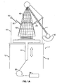
FIG. 1 is a diagrammatic view of the apparatus of the preferred embodiment of the present invention, without any netting in place. -
FIG. 1A is the apparatus ofFIG. 1 , with the netting shown. -
FIG. 2 is a perspective view of the netting tube of the apparatus ofFIG. 1 . -
FIG. 3A is a side cross-sectional view of the second tube of the apparatus ofFIG. 1 . -
FIG. 3B is a side view of the second tube ofFIG. 3A . -
FIG. 3C is a side view of the tube cap ring of the apparatus ofFIG. 1 . -
FIG. 3D is a top view of the tube cap ring ofFIG. 3C . -
FIG. 3E is a perspective view of the second tube ofFIG. 3B . -
FIG. 3F is a top view of the lower tube ring of the apparatus ofFIG. 1 . -
FIG. 3G is a side view of the lower tube ring ofFIG. 3F . -
FIG. 3H is a side cross-sectional view of the netting tube, second tube, tube cap ring, and lower tube ring of the apparatus ofFIG. 1 . -
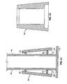
FIG. 3I is a side cross-sectional view of another embodiment of the second tube. -
FIG. 3J is a side cross-sectional view of the second tube ofFIG. 3I mounted on the netting tube of the apparatus ofFIG. 1 . -
FIG. 4A is a side cross-sectional view of another embodiment of the second tube. -
FIG. 4B is a side cross-sectional view of the second tube ofFIG. 4A , mounted on the netting tube of the apparatus ofFIG. 1 . -
FIG. 4C is a top view of the second tube ofFIG. 4A . - The organization and manner of the preferred embodiments of the invention, together with further objects and advantages thereof, may best be understood by reference to the following description of the preferred embodiments of the invention, taken in connection with the drawings:
- The preferred embodiment of the
net rucking apparatus 2 is shown in elevation view inFIG. 1 without the netting 4 present, and inFIG. 1A with netting 4 present. Theapparatus 2 comprises aframe 10, a nettingtube 40, and asecond tube 50. Theframe 10 haslegs 12 to support it, andupper arms 14 that hold anet rucker head 16. Thenet rucker head 16 defines apassage 18 through which thenetting tube 40 andsecond tube 50 pass. Attached to thenet rucker head 16 and extending into thepassage 18 is a plurality of spring-loadedfingers 20. - A
moveable platform 22 sits on top of theframe 10. It is configured to travel in an upward and downward direction, powered by a lifting means. In the preferred embodiment, the lifting means comprises a reciprocating air-actuatedcylinder 24, connected to anair supply 26 which is controlled by a control means 28. In other embodiments, other lifting means that can provide reciprocating axial action are used, such as a gear arrangement, another type of hydraulic cylinder, or a treadle. In the preferred embodiment, control means 28 is a microprocessor with an application-specific program written to it. In other embodiments, a digital or analog controller is used. In yet other embodiments,apparatus 2 is controlled manually. - Netting 4 is placed in a
net tray 30 that is attached to anupper arm 14. The leading edge of thenetting 4 travels up to anet guide 32, attached to and above one of theupper arms 14 and above thenet rucker head 16. Thenet guide 32 leads thenetting 4 down through thepassage 18 as will hereinafter be described. - Netting
tube 40, shown enlarged inFIG. 2 , is a hollow cylinder with abase plate 42. In the preferred embodiment, nettingtube 40 is stainless steel, for use in a food-processing environment. There are attachment means 44 onbaseplate 42, to hold nettingtube 40 securely tomoveable platform 22. Attachment means 44 are preferably identical to the means by which nettingtube 40 will be attached to a sausage-making machine after rucking of thenetting 4. Attachment means 44 is preferably a locking clamp. In other embodiments, attachment means is a nut-and-bolt arrangement, a bayonet attachment, a threading system, or any system to hold nettingtube 40 firmly tomoveable platform 22. -
Second tube 50 is a hollow member in the shape of a frustum, the basal part of a solid cone or pyramid formed by cutting off the top by a plane parallel to the base. In a first embodiment,second tube 50 preferably has a frusto-conical shape. Accordingly,second tube 50 has a circular cross-section taken perpendicular to the axis ofsecond tube 50. In other embodiments,second tube 50 has a frusto-pyramidal shape. In these embodiments, second tube has flat, trapezoidal faces, so that a cross-section taken perpendicular to the axis is polygonal. In other embodiments, a cross-section will have another shape, such as oval. Preferably,second tube 50 is made of a heavy plastic, to allow netting 4 to slide over it easily. -
Second tube 50, being a tube, has a bore therethrough. In the illustrated embodiment shown inFIGS. 3A through 3G ,second tube 50 has a frusto-conical shape and the bore matches the frusto-conical shape of the outside ofsecond tube 50. In other embodiments,second tube 50 has a frusto-pyramidal shape and the bore matches the frusto-pyramidal shape of the outside ofsecond tube 50. In yet other embodiments, the outside ofsecond tube 50 has one of a frusto-conical shape and a frusto-pyramidal shape, and the bore has the other of a frusto-conical shape and a frusto-pyramidal shape. - A first embodiment of
second tube 50 is shown inFIGS. 3A through 3H .Second tube 50, as shown inFIG. 3E , has a circular cross section taken perpendicular to the axis ofsecond tube 50. Accordingly,second tube 50 has an inner diameter ID1 at the bottom, an outer diameter OD1 at the bottom, an inner diameter ID2 at the top, and an outer diameter OD2 at the top. Second tube has a height h. - In this embodiment,
second tube 50 has atube cap ring 52 affixed to the top.Tube cap ring 52 is a toroidal element with a notchededge 53, as shown inFIG. 3C , so that it has one outer diameter equal to OD2 ofsecond tube 50, and a second outer diameter equal to ID2 ofsecond tube 50, allowing thetube cap ring 52 to snap onto the top end of thesecond tube 50.Tube cap ring 52 preferably fits intosecond tube 50 with an interference fit. In other embodiments,tube cap ring 52 is attached tosecond tube 50 by glue, welding, threads, or fasteners such as screws, rivets, or bolts. In yet another embodiment,tube cap ring 52 is formed integrally withsecond tube 50. -
Tube cap ring 52 has an inner diameter ID3 just slightly larger than the outer diameter of nettingtube 40, as shown inFIG. 3D , so thattube cap ring 52 can slide easily co-axially to nettingtube 40.Tube cap ring 52 is rounded or at least angled on the side opposite the notched edge, to allow netting 4 to slide over it easily, as the purpose oftube cap ring 52 is to prevent snagging. In this embodiment, tube cap ring is circular in cross section taken perpendicular to the axis ofsecond tube 50 when tube cap ring is affixed tosecond tube 50. In other embodiments,tube cap ring 52 has a polygonal cross section to match the frusto-pyramidal shape ofsecond tube 50. In other embodiments,tube cap ring 52 has a one of a circular cross section and a polygonal cross section on its outside, to match the outer shape ofsecond tube 50, and the other of a circular cross section and a polygonal cross section on its inside, to match the shape of the bore ofsecond tube 50. - A
lower tube ring 54, shown inFIGS. 3A ,3F , and3G , is also of a toroidal shape and is placed inside and coaxially to thesecond tube 50.Lower tube ring 54 has an outer diameter equal to the inner diameter ofsecond tube 50 at a point just above the bottom ofsecond tube 50. In the preferred embodiment,lower tube ring 54 has a slanted outside wall, having the same slope assecond tube 50.Lower tube ring 54 is attached to second tube 50 a short distance, preferably an inch, from the bottom ofsecond tube 50. Accordingly,lower tube ring 54 forms an interference fit insidesecond tube 50, so thatlower tube ring 54 stays firmly situated insidesecond tube 50, as shown in cross-section inFIGS. 3A and3H . In another embodiment,lower tube ring 54 is attached tosecond tube 50 by glue, welding, threads, or fasteners such as screws, rivets, or bolts. In yet another embodiment,lower tube ring 54 is formed integrally withsecond tube 50. - The inner diameter of
lower tube ring 54 is, liketube cap ring 52, just slightly larger than the outer diameter of nettingtube 40, so thatlower tube ring 54 can easily slide axially to nettingtube 40, as shown in elevation view inFIG. 3B and in partial cutaway cross-sectional view inFIG. 3H . Becauselower tube ring 54 is placed a short distance from the bottom end of thesecond tube 50, anannular space 56 is defined by nettingtube 40,lower tube ring 54, andsecond tube 50, as shown inFIG. 3H . Whentube cap ring 52 andlower tube ring 54 are put in place onsecond tube 50,tube cap ring 52 andlower tube ring 54 slide easily along nettingtube 40, so thatsecond tube 50 travels coaxially to nettingtube 40. - In this illustrated embodiment, having a
tube cap ring 52, only a singlelower tube ring 54 is necessary. In other embodiments, extra tube rings are placed insidesecond tube 50. One such other embodiment is shown inFIGS. 3I and3J . In this embodiment,lower tube ring 54 is used, as described above, to allowsecond tube 50 to move coaxially along nettingtube 40 and to formannular space 56. Please note thatsecond tube 50 in this embodiment has rounded edges at its top to prevent snagging of netting. Anupper tube ring 60, substantially identical tolower tube ring 54 except smaller, is also mounted withinsecond tube 50. Likelower tube ring 54,upper tube ring 60 has a toroidal shape. It has an inner diameter just larger than the outer diameter of nettingtube 40 and an outer diameter equal to the inner diameter ofsecond tube 50 at a point at or just below the top ofsecond tube 50. Likelower tube ring 54,upper tube ring 60 preferably has a slanted outside wall, having the same slope assecond tube 50.Upper tube ring 60 therefore forms an interference fit insidesecond tube 50, so thatupper tube ring 60 stays firmly situated insidesecond tube 50, as shown in cross-section inFIG. 3G . In another embodiment,upper tube ring 60 is attached tosecond tube 50 by glue, welding, threads, or fasteners such as screws, rivets, or bolts. In yet another embodiment,upper tube ring 60 is formed integrally withsecond tube 50. - In other embodiments,
lower tube ring 54 andupper tube ring 60, rather than being toroidal, have a polygonal shape in cross section taken perpendicular tosecond tube 50, to match the shape of the bore ofsecond tube 50. In these embodiments,lower tube ring 54 andupper tube ring 60 still have a circular inner diameter to match nettingtube 40. - Another embodiment of
second tube 50 is shown inFIGS. 4A ,4B, and 4C . In this embodiment,second tube 50 has a frusto-conical shape on the outside and acylindrical bore 62 therethrough. Please note thatsecond tube 50 in this embodiment has rounded edges at its top to prevent snagging of netting.Bore 62 has a diameter through most of its length slightly greater than the outer diameter of nettingtube 40, so that second tube slides co-axially along nettingtube 40. At the bottom, however, bore 62 increases in diameter, because of a notch in the bottom ofsecond tube 50, to formannular space 56. - In another embodiment,
second tube 50 has a frusto-pyramidal shape on the outside andcylindrical bore 62 therethrough. - The method of use of the
apparatus 2 is substantially the same for the illustrated embodiments ofsecond tube 50. Nettingtube 40 is placed onmoveable platform 22 and attached by attachment means 44. In a first embodiment,second tube 50, with its tworings tube 40. In another embodiment,second tube 50, with at least rings 54, 60 in place, is mounted over nettingtube 40. In yet another embodiment,second tube 50 does not need rings, as described in connection withFIGS. 4A and4B . -
Moveable platform 22, by its reciprocating motion, causes nettingtube 40, surrounded bysecond tube 50, to travel in a reciprocating, coaxial movement throughpassage 18. Spring-loadedfingers 20 are arranged so that they conform to the diameter ofsecond tube 50 and nettingtube 40. During downward travel ofsecond tube 50 and nettingtube 40,fingers 20 are pushed away circumferentially fromtubes second tube 50 and nettingtube 40 travel upward, spring-loadedfingers 20 snap back to engage netting 4 and prevent it from traveling. - Accordingly, in use netting 4 is placed in
net tray 30 and the free end is run throughnet guide 32 and oversecond tube 50, to at least a point belowfingers 20. Asmoveable platform 22 moves down, it pulls netting 4 down with it,past fingers 20. When reciprocatingplatform 22 reaches the bottom of its downstroke,cylinder 24 reverses movement to an upward direction, pushingnetting tube 40 andsecond tube 50 throughpassage 18.Fingers 20 now engage netting 4 onsecond tube 50 and prevent it from traveling.Second tube 50 nevertheless continues in an upward path, as netting 4 can slide over the smooth plastic surface ofsecond tube 50, so netting 4 moves downward relative tosecond tube 50. Thus, asmoveable platform 22 reverses again in its reciprocating motion, netting 4 is pulled down toward the bottom ofsecond tube 50. When netting 4 gets to the bottom ofsecond tube 50,fingers 20 push netting 4 offsecond tube 50 and netting 4 contracts around the smaller-diameter netting tube 40. Accordingly,second tube 50 is forced slightly upward, relative to nettingtube 40,fingers 20, as netting 4 is rucked onto the bottom of nettingtube 40. On each upward stroke ofmoveable platform 22,more netting 4 is pushed byfingers 20 offsecond tube 50 and onto nettingtube 40.Fingers 20 push netting 4 inward, causing it to fillannular space 56. Because ofannular space 56, netting 4 is rucked neatly and several layers thick. Accordingly,apparatus 2 will ruck approximately four to five times asmuch netting 4 onto a given size of nettingtube 40 as a conventional rucker without this annular space. - In yet another embodiment,
fingers 20 are replaced by wheels. In this embodiment, the wheels are configured to rotate in only a single direction, and to lock in the opposite direction of rotation. Accordingly, asmoveable platform 22 moves down, it pulls netting 4 down with it, as described above, past the wheels, which rotate freely in this direction. When reciprocatingplatform 22 reaches the bottom of its downstroke,cylinder 24 reverses movement to an upward direction, pushingnetting tube 40 andsecond tube 50 throughpassage 18, as described above. The wheels now engage netting 4 onsecond tube 50 and, being locked to prevent rotation in this direction, prevent netting 4 from traveling. The operation ofapparatus 2 is otherwise identical to the previously described embodiments. - While preferred embodiments of the present invention are shown and described, it is envisioned that those skilled in the art may devise modifications of the present invention without departing from the scope of the appended claims.
Claims (14)
- An apparatus (2) for rucking netting (4) onto a tube, comprising:a frame (10) having an axis;a passage (18) along said axis;means for reciprocating movement (22, 24, 26) along said axis;a netting tube (40) releasably attachable to said means for reciprocating movement;a second tube (50) having a top end and a bottom end, said bottom end proximate to said means for reciprocating movement and said top end distal to said means for reciprocating movement, said second tube being slidable co- axially to said netting tube;an annular space defined at least by said second tube (50) and said netting tube (40); andspring-loaded fingers (20) attached to said frame and extending into said passage characterised in that said second tube (50) comprises a frustum having a bore, said frustum extending from said top end to said bottom end.
- The apparatus of claim 1, further comprising means to prevent snagging to a netting on said second tube (50).
- The apparatus of claim 1, further comprising a tube cap (52) attached to said second tube (50) and having a tapered surface.
- The apparatus of claim 1, further comprising means (28) to control said means for reciprocating movement (22, 24, 26).
- The apparatus of claim 1, whereby said means for reciprocating movement (22, 24, 26) comprises an air-actuated cylinder (24) and an air supply (26).
- The apparatus of claim 1, wherein said annular space comprises a notch in an end of said second tube (50).
- The apparatus of claim 1, wherein said annular space is formed by a tube ring (60), said second tube (50), and said netting tube (40), said tube ring (60) being attached to said second tube (50) within said bore of said second tube (50) and slidable co-axially over said netting tube (40).
- The apparatus of claim 7, further comprising a second tube ring (54) within said bore of said second tube (50).
- The apparatus of claim 1, wherein said frustum has a frusto-conical shape.
- The apparatus of claim 1, wherein said frustum has a frusto-pyramidal shape.
- A method of rucking netting onto a netting tube (40), comprising:attaching a netting tube (40) to a moveable platform (22);mounting a second tube (50) axially over said netting tube (40);placing an end of a netting (4) over said second tube (50);forming an annular space between said netting tube (40) and said second tube (50); andmoving said second tube (50) reciprocatingly through spring-loaded fingers (20);characterised in that said second tube (50) comprises a frustum having a bore therethrough, said frustum extending from a top end of said tube to a bottom end of said tube (50).
- The method of claim 10, further comprising preventing snagging of said netting (4).
- The method of claim 10, wherein said frustum has a frusto-conical shape.
- The method of claim 10, wherein said frustum has a frusto-pyramidal shape.
Priority Applications (1)
| Application Number | Priority Date | Filing Date | Title |
|---|---|---|---|
| PL08744068T PL2129227T3 (en) | 2007-03-19 | 2008-03-19 | Net rucking apparatus and method |
Applications Claiming Priority (3)
| Application Number | Priority Date | Filing Date | Title |
|---|---|---|---|
| US89561507P | 2007-03-19 | 2007-03-19 | |
| PCT/US2008/057510 WO2008115994A1 (en) | 2007-03-19 | 2008-03-19 | Net rucking apparatus and method |
| US12/051,307 US7641542B2 (en) | 2007-03-19 | 2008-03-19 | Net rucking apparatus and method |
Publications (3)
| Publication Number | Publication Date |
|---|---|
| EP2129227A1 EP2129227A1 (en) | 2009-12-09 |
| EP2129227A4 EP2129227A4 (en) | 2012-08-22 |
| EP2129227B1 true EP2129227B1 (en) | 2013-07-17 |
Family
ID=39766426
Family Applications (1)
| Application Number | Title | Priority Date | Filing Date |
|---|---|---|---|
| EP08744068.1A Not-in-force EP2129227B1 (en) | 2007-03-19 | 2008-03-19 | Net rucking apparatus and method |
Country Status (8)
| Country | Link |
|---|---|
| US (1) | US7641542B2 (en) |
| EP (1) | EP2129227B1 (en) |
| AU (1) | AU2008228893A1 (en) |
| BR (1) | BRPI0809032A2 (en) |
| CA (1) | CA2682197C (en) |
| ES (1) | ES2436791T3 (en) |
| PL (1) | PL2129227T3 (en) |
| WO (1) | WO2008115994A1 (en) |
Families Citing this family (6)
| Publication number | Priority date | Publication date | Assignee | Title |
|---|---|---|---|---|
| US7488243B2 (en) * | 2004-11-01 | 2009-02-10 | Tipper Tie, Inc. | Systems with horns that extend into netting chutes and having cooperating deruckers for producing encased products and related devices, methods and computer program products |
| US7704129B2 (en) * | 2005-07-12 | 2010-04-27 | Tipper Tie, Inc. | Ruckers capable of rucking fixed diameter coverings and associated devices, methods, systems and computer program products |
| US7775859B2 (en) * | 2005-07-25 | 2010-08-17 | Tipper Tie, Inc. | Low profile ruckers capable of rucking fixed diameter coverings and associated devices, methods, systems and computer program products |
| USD729294S1 (en) | 2013-08-26 | 2015-05-12 | Tipper Tie, Inc. | Gripper for automated ruckers, reruckers, deruckers and/or skin brakes |
| US10011380B2 (en) | 2013-08-26 | 2018-07-03 | Tipper Tie, Inc. | Ruckers, reruckers, deruckers and/or skin brakes with stacked gripper layers and related grippers |
| US9877492B1 (en) * | 2017-06-26 | 2018-01-30 | Tipper Tie, Inc. | Additional casing for slack filling |
Family Cites Families (16)
| Publication number | Priority date | Publication date | Assignee | Title |
|---|---|---|---|---|
| US3477860A (en) * | 1965-09-15 | 1969-11-11 | Michael A Sartore | Method for netting meat |
| US3703065A (en) * | 1970-11-06 | 1972-11-21 | Arnold Soodalter | Sleeving apparatus |
| IT942983B (en) * | 1971-11-27 | 1973-04-02 | Cherio V | SEMI-AUTOMATIC MACHINE FOR THE BAGGING OF FOOD PRODUCTS PARTICULARLY ROASTED IN TUBULAR NETWORK AND FOR CONTINUOUS STORAGE OF TUBULAR NETWORK ON BAGGING PIPES |
| SE381172B (en) * | 1973-01-03 | 1975-12-01 | Pactosan Ab | DEVICE FOR PACKING WASTE IN A HOSE |
| US4016704A (en) * | 1975-07-02 | 1977-04-12 | Masaaki Fujio | Method and apparatus for encapsulating container with tubular wrapping member |
| NL162874C (en) * | 1977-04-07 | 1982-10-18 | Amtac Bv | APPARATUS FOR PACKING A CLOT OF A TREE, BUSH OR PLANT. |
| US4133164A (en) * | 1977-09-28 | 1979-01-09 | Industrial Knitting, Inc. | Split horn arrangement |
| DE3431521A1 (en) | 1984-08-28 | 1986-03-06 | Naturin-Werk Becker & Co, 6940 Weinheim | METHOD FOR PRODUCING MEAT PRODUCTS COOKED IN COMPACT FORM IN A NET AND DEVICE FOR PROCESSING MEAT PREPARATION |
| US4924552A (en) | 1989-06-30 | 1990-05-15 | The Brechteen Company | Net rucker |
| US5273481A (en) * | 1992-08-20 | 1993-12-28 | Brechteen Co. | Net rucker |
| GB2336826B (en) * | 1998-05-02 | 2002-01-23 | Trunature Ltd | Loading elasticated netting onto tubes |
| DE10020856B9 (en) * | 2000-04-28 | 2007-10-04 | MSK-Verpackungs-Systeme Gesellschaft mit beschränkter Haftung | Device for wrapping piece or packaged goods |
| HUP0500787A3 (en) | 2002-02-06 | 2009-07-28 | Viscofan Sa | Method and apparatus for the automatic stuffing of meat products into a double casing comprising a sheet and a net |
| JP2006518588A (en) * | 2003-02-25 | 2006-08-17 | ビスコファン・ソシエダッド・アノニマ | Multi-layer arrangement of tubular nets on a support tube and devices and methods for obtaining the same |
| US7051415B2 (en) * | 2003-09-30 | 2006-05-30 | Poly-Clip System Corp. | Net rucking apparatus and method |
| US7441386B2 (en) * | 2006-10-27 | 2008-10-28 | Poly-Clip System Corp. | Apparatus for forming tubes in nets |
-
2008
- 2008-03-19 WO PCT/US2008/057510 patent/WO2008115994A1/en active Application Filing
- 2008-03-19 BR BRPI0809032-7A2A patent/BRPI0809032A2/en not_active Application Discontinuation
- 2008-03-19 PL PL08744068T patent/PL2129227T3/en unknown
- 2008-03-19 AU AU2008228893A patent/AU2008228893A1/en not_active Abandoned
- 2008-03-19 ES ES08744068.1T patent/ES2436791T3/en active Active
- 2008-03-19 CA CA2682197A patent/CA2682197C/en not_active Expired - Fee Related
- 2008-03-19 US US12/051,307 patent/US7641542B2/en not_active Expired - Fee Related
- 2008-03-19 EP EP08744068.1A patent/EP2129227B1/en not_active Not-in-force
Also Published As
| Publication number | Publication date |
|---|---|
| AU2008228893A1 (en) | 2008-09-25 |
| WO2008115994A1 (en) | 2008-09-25 |
| BRPI0809032A2 (en) | 2014-10-07 |
| ES2436791T3 (en) | 2014-01-07 |
| US20080248735A1 (en) | 2008-10-09 |
| PL2129227T3 (en) | 2014-02-28 |
| CA2682197A1 (en) | 2008-09-25 |
| US7641542B2 (en) | 2010-01-05 |
| EP2129227A4 (en) | 2012-08-22 |
| EP2129227A1 (en) | 2009-12-09 |
| CA2682197C (en) | 2015-11-17 |
Similar Documents
| Publication | Publication Date | Title |
|---|---|---|
| EP2129227B1 (en) | Net rucking apparatus and method | |
| EP1667813B1 (en) | Improved net rucking apparatus and method | |
| US8047900B2 (en) | Loading caps for ruckers capable of rucking fixed diameter coverings | |
| EP2074029B1 (en) | Apparatus and method for forming tubes in nets | |
| US4028775A (en) | Apparatus for inserting a sizing disc into a tubular casing | |
| US7775859B2 (en) | Low profile ruckers capable of rucking fixed diameter coverings and associated devices, methods, systems and computer program products | |
| CA2093086C (en) | Net rucker | |
| CA2016967A1 (en) | Dual tube stuffing horn with expanding spring for size control | |
| US4809403A (en) | Collapsible presizing rings | |
| US20050048886A1 (en) | Net loader | |
| NZ535035A (en) | Hand operated shirring machine | |
| AU2004205239A1 (en) | A net loader | |
| CA2748261A1 (en) | Improved forming wire | |
| NZ534906A (en) | A device for filling tubular casings with edible material including a tube and tube supporting means | |
| AU2003206497A1 (en) | Hand operated shirring machine |
Legal Events
| Date | Code | Title | Description |
|---|---|---|---|
| PUAI | Public reference made under article 153(3) epc to a published international application that has entered the european phase |
Free format text: ORIGINAL CODE: 0009012 |
|
| 17P | Request for examination filed |
Effective date: 20091009 |
|
| AK | Designated contracting states |
Kind code of ref document: A1 Designated state(s): AT BE BG CH CY CZ DE DK EE ES FI FR GB GR HR HU IE IS IT LI LT LU LV MC MT NL NO PL PT RO SE SI SK TR |
|
| DAX | Request for extension of the european patent (deleted) | ||
| A4 | Supplementary search report drawn up and despatched |
Effective date: 20120725 |
|
| RIC1 | Information provided on ipc code assigned before grant |
Ipc: A22C 13/02 20060101AFI20120719BHEP |
|
| GRAP | Despatch of communication of intention to grant a patent |
Free format text: ORIGINAL CODE: EPIDOSNIGR1 |
|
| GRAS | Grant fee paid |
Free format text: ORIGINAL CODE: EPIDOSNIGR3 |
|
| GRAA | (expected) grant |
Free format text: ORIGINAL CODE: 0009210 |
|
| AK | Designated contracting states |
Kind code of ref document: B1 Designated state(s): AT BE BG CH CY CZ DE DK EE ES FI FR GB GR HR HU IE IS IT LI LT LU LV MC MT NL NO PL PT RO SE SI SK TR |
|
| REG | Reference to a national code |
Ref country code: GB Ref legal event code: FG4D |
|
| REG | Reference to a national code |
Ref country code: CH Ref legal event code: EP |
|
| REG | Reference to a national code |
Ref country code: IE Ref legal event code: FG4D |
|
| REG | Reference to a national code |
Ref country code: AT Ref legal event code: REF Ref document number: 621604 Country of ref document: AT Kind code of ref document: T Effective date: 20130815 |
|
| REG | Reference to a national code |
Ref country code: DE Ref legal event code: R096 Ref document number: 602008026075 Country of ref document: DE Effective date: 20130912 |
|
| REG | Reference to a national code |
Ref country code: AT Ref legal event code: MK05 Ref document number: 621604 Country of ref document: AT Kind code of ref document: T Effective date: 20130717 |
|
| REG | Reference to a national code |
Ref country code: NL Ref legal event code: VDEP Effective date: 20130717 |
|
| REG | Reference to a national code |
Ref country code: LT Ref legal event code: MG4D |
|
| REG | Reference to a national code |
Ref country code: ES Ref legal event code: FG2A Ref document number: 2436791 Country of ref document: ES Kind code of ref document: T3 Effective date: 20140107 |
|
| PG25 | Lapsed in a contracting state [announced via postgrant information from national office to epo] |
Ref country code: BE Free format text: LAPSE BECAUSE OF FAILURE TO SUBMIT A TRANSLATION OF THE DESCRIPTION OR TO PAY THE FEE WITHIN THE PRESCRIBED TIME-LIMIT Effective date: 20130717 Ref country code: NO Free format text: LAPSE BECAUSE OF FAILURE TO SUBMIT A TRANSLATION OF THE DESCRIPTION OR TO PAY THE FEE WITHIN THE PRESCRIBED TIME-LIMIT Effective date: 20131017 Ref country code: PT Free format text: LAPSE BECAUSE OF FAILURE TO SUBMIT A TRANSLATION OF THE DESCRIPTION OR TO PAY THE FEE WITHIN THE PRESCRIBED TIME-LIMIT Effective date: 20131118 Ref country code: HR Free format text: LAPSE BECAUSE OF FAILURE TO SUBMIT A TRANSLATION OF THE DESCRIPTION OR TO PAY THE FEE WITHIN THE PRESCRIBED TIME-LIMIT Effective date: 20130717 Ref country code: SE Free format text: LAPSE BECAUSE OF FAILURE TO SUBMIT A TRANSLATION OF THE DESCRIPTION OR TO PAY THE FEE WITHIN THE PRESCRIBED TIME-LIMIT Effective date: 20130717 Ref country code: CY Free format text: LAPSE BECAUSE OF FAILURE TO SUBMIT A TRANSLATION OF THE DESCRIPTION OR TO PAY THE FEE WITHIN THE PRESCRIBED TIME-LIMIT Effective date: 20130814 Ref country code: LT Free format text: LAPSE BECAUSE OF FAILURE TO SUBMIT A TRANSLATION OF THE DESCRIPTION OR TO PAY THE FEE WITHIN THE PRESCRIBED TIME-LIMIT Effective date: 20130717 Ref country code: AT Free format text: LAPSE BECAUSE OF FAILURE TO SUBMIT A TRANSLATION OF THE DESCRIPTION OR TO PAY THE FEE WITHIN THE PRESCRIBED TIME-LIMIT Effective date: 20130717 Ref country code: IS Free format text: LAPSE BECAUSE OF FAILURE TO SUBMIT A TRANSLATION OF THE DESCRIPTION OR TO PAY THE FEE WITHIN THE PRESCRIBED TIME-LIMIT Effective date: 20131117 |
|
| PG25 | Lapsed in a contracting state [announced via postgrant information from national office to epo] |
Ref country code: SI Free format text: LAPSE BECAUSE OF FAILURE TO SUBMIT A TRANSLATION OF THE DESCRIPTION OR TO PAY THE FEE WITHIN THE PRESCRIBED TIME-LIMIT Effective date: 20130717 Ref country code: FI Free format text: LAPSE BECAUSE OF FAILURE TO SUBMIT A TRANSLATION OF THE DESCRIPTION OR TO PAY THE FEE WITHIN THE PRESCRIBED TIME-LIMIT Effective date: 20130717 Ref country code: NL Free format text: LAPSE BECAUSE OF FAILURE TO SUBMIT A TRANSLATION OF THE DESCRIPTION OR TO PAY THE FEE WITHIN THE PRESCRIBED TIME-LIMIT Effective date: 20130717 Ref country code: LV Free format text: LAPSE BECAUSE OF FAILURE TO SUBMIT A TRANSLATION OF THE DESCRIPTION OR TO PAY THE FEE WITHIN THE PRESCRIBED TIME-LIMIT Effective date: 20130717 Ref country code: GR Free format text: LAPSE BECAUSE OF FAILURE TO SUBMIT A TRANSLATION OF THE DESCRIPTION OR TO PAY THE FEE WITHIN THE PRESCRIBED TIME-LIMIT Effective date: 20131018 |
|
| REG | Reference to a national code |
Ref country code: PL Ref legal event code: T3 |
|
| PG25 | Lapsed in a contracting state [announced via postgrant information from national office to epo] |
Ref country code: CY Free format text: LAPSE BECAUSE OF FAILURE TO SUBMIT A TRANSLATION OF THE DESCRIPTION OR TO PAY THE FEE WITHIN THE PRESCRIBED TIME-LIMIT Effective date: 20130717 |
|
| PG25 | Lapsed in a contracting state [announced via postgrant information from national office to epo] |
Ref country code: SK Free format text: LAPSE BECAUSE OF FAILURE TO SUBMIT A TRANSLATION OF THE DESCRIPTION OR TO PAY THE FEE WITHIN THE PRESCRIBED TIME-LIMIT Effective date: 20130717 Ref country code: EE Free format text: LAPSE BECAUSE OF FAILURE TO SUBMIT A TRANSLATION OF THE DESCRIPTION OR TO PAY THE FEE WITHIN THE PRESCRIBED TIME-LIMIT Effective date: 20130717 Ref country code: RO Free format text: LAPSE BECAUSE OF FAILURE TO SUBMIT A TRANSLATION OF THE DESCRIPTION OR TO PAY THE FEE WITHIN THE PRESCRIBED TIME-LIMIT Effective date: 20130717 Ref country code: DK Free format text: LAPSE BECAUSE OF FAILURE TO SUBMIT A TRANSLATION OF THE DESCRIPTION OR TO PAY THE FEE WITHIN THE PRESCRIBED TIME-LIMIT Effective date: 20130717 Ref country code: CZ Free format text: LAPSE BECAUSE OF FAILURE TO SUBMIT A TRANSLATION OF THE DESCRIPTION OR TO PAY THE FEE WITHIN THE PRESCRIBED TIME-LIMIT Effective date: 20130717 |
|
| PLBE | No opposition filed within time limit |
Free format text: ORIGINAL CODE: 0009261 |
|
| STAA | Information on the status of an ep patent application or granted ep patent |
Free format text: STATUS: NO OPPOSITION FILED WITHIN TIME LIMIT |
|
| PGFP | Annual fee paid to national office [announced via postgrant information from national office to epo] |
Ref country code: IT Payment date: 20140319 Year of fee payment: 7 |
|
| REG | Reference to a national code |
Ref country code: DE Ref legal event code: R082 Ref document number: 602008026075 Country of ref document: DE Representative=s name: EISENFUEHR SPEISER PATENTANWAELTE RECHTSANWAEL, DE |
|
| 26N | No opposition filed |
Effective date: 20140422 |
|
| REG | Reference to a national code |
Ref country code: DE Ref legal event code: R097 Ref document number: 602008026075 Country of ref document: DE Effective date: 20140422 |
|
| PG25 | Lapsed in a contracting state [announced via postgrant information from national office to epo] |
Ref country code: LU Free format text: LAPSE BECAUSE OF FAILURE TO SUBMIT A TRANSLATION OF THE DESCRIPTION OR TO PAY THE FEE WITHIN THE PRESCRIBED TIME-LIMIT Effective date: 20140319 |
|
| REG | Reference to a national code |
Ref country code: CH Ref legal event code: PL |
|
| REG | Reference to a national code |
Ref country code: IE Ref legal event code: MM4A |
|
| PG25 | Lapsed in a contracting state [announced via postgrant information from national office to epo] |
Ref country code: CH Free format text: LAPSE BECAUSE OF NON-PAYMENT OF DUE FEES Effective date: 20140331 Ref country code: LI Free format text: LAPSE BECAUSE OF NON-PAYMENT OF DUE FEES Effective date: 20140331 Ref country code: IE Free format text: LAPSE BECAUSE OF NON-PAYMENT OF DUE FEES Effective date: 20140319 |
|
| PG25 | Lapsed in a contracting state [announced via postgrant information from national office to epo] |
Ref country code: IT Free format text: LAPSE BECAUSE OF NON-PAYMENT OF DUE FEES Effective date: 20150319 |
|
| PG25 | Lapsed in a contracting state [announced via postgrant information from national office to epo] |
Ref country code: MT Free format text: LAPSE BECAUSE OF FAILURE TO SUBMIT A TRANSLATION OF THE DESCRIPTION OR TO PAY THE FEE WITHIN THE PRESCRIBED TIME-LIMIT Effective date: 20130717 |
|
| REG | Reference to a national code |
Ref country code: FR Ref legal event code: PLFP Year of fee payment: 9 |
|
| PG25 | Lapsed in a contracting state [announced via postgrant information from national office to epo] |
Ref country code: MC Free format text: LAPSE BECAUSE OF FAILURE TO SUBMIT A TRANSLATION OF THE DESCRIPTION OR TO PAY THE FEE WITHIN THE PRESCRIBED TIME-LIMIT Effective date: 20130717 Ref country code: BG Free format text: LAPSE BECAUSE OF FAILURE TO SUBMIT A TRANSLATION OF THE DESCRIPTION OR TO PAY THE FEE WITHIN THE PRESCRIBED TIME-LIMIT Effective date: 20130717 |
|
| PGFP | Annual fee paid to national office [announced via postgrant information from national office to epo] |
Ref country code: PL Payment date: 20160308 Year of fee payment: 9 Ref country code: FR Payment date: 20160322 Year of fee payment: 9 Ref country code: GB Payment date: 20160322 Year of fee payment: 9 |
|
| PG25 | Lapsed in a contracting state [announced via postgrant information from national office to epo] |
Ref country code: TR Free format text: LAPSE BECAUSE OF FAILURE TO SUBMIT A TRANSLATION OF THE DESCRIPTION OR TO PAY THE FEE WITHIN THE PRESCRIBED TIME-LIMIT Effective date: 20130717 Ref country code: HU Free format text: LAPSE BECAUSE OF FAILURE TO SUBMIT A TRANSLATION OF THE DESCRIPTION OR TO PAY THE FEE WITHIN THE PRESCRIBED TIME-LIMIT; INVALID AB INITIO Effective date: 20080319 |
|
| GBPC | Gb: european patent ceased through non-payment of renewal fee |
Effective date: 20170319 |
|
| REG | Reference to a national code |
Ref country code: FR Ref legal event code: ST Effective date: 20171130 |
|
| PG25 | Lapsed in a contracting state [announced via postgrant information from national office to epo] |
Ref country code: FR Free format text: LAPSE BECAUSE OF NON-PAYMENT OF DUE FEES Effective date: 20170331 |
|
| PG25 | Lapsed in a contracting state [announced via postgrant information from national office to epo] |
Ref country code: GB Free format text: LAPSE BECAUSE OF NON-PAYMENT OF DUE FEES Effective date: 20170319 |
|
| PG25 | Lapsed in a contracting state [announced via postgrant information from national office to epo] |
Ref country code: PL Free format text: LAPSE BECAUSE OF NON-PAYMENT OF DUE FEES Effective date: 20170319 |
|
| PGFP | Annual fee paid to national office [announced via postgrant information from national office to epo] |
Ref country code: ES Payment date: 20190424 Year of fee payment: 12 Ref country code: DE Payment date: 20190404 Year of fee payment: 12 |
|
| REG | Reference to a national code |
Ref country code: DE Ref legal event code: R119 Ref document number: 602008026075 Country of ref document: DE |
|
| PG25 | Lapsed in a contracting state [announced via postgrant information from national office to epo] |
Ref country code: DE Free format text: LAPSE BECAUSE OF NON-PAYMENT OF DUE FEES Effective date: 20201001 |
|
| REG | Reference to a national code |
Ref country code: ES Ref legal event code: FD2A Effective date: 20210805 |
|
| PG25 | Lapsed in a contracting state [announced via postgrant information from national office to epo] |
Ref country code: ES Free format text: LAPSE BECAUSE OF NON-PAYMENT OF DUE FEES Effective date: 20200320 |