EP2129169A2 - Measurement of sound pressure level and phase at eardrum by sensing eardrum vibration - Google Patents
Measurement of sound pressure level and phase at eardrum by sensing eardrum vibration Download PDFInfo
- Publication number
- EP2129169A2 EP2129169A2 EP09161477A EP09161477A EP2129169A2 EP 2129169 A2 EP2129169 A2 EP 2129169A2 EP 09161477 A EP09161477 A EP 09161477A EP 09161477 A EP09161477 A EP 09161477A EP 2129169 A2 EP2129169 A2 EP 2129169A2
- Authority
- EP
- European Patent Office
- Prior art keywords
- tympanic membrane
- user
- eardrum
- vibration
- sensor
- Prior art date
- Legal status (The legal status is an assumption and is not a legal conclusion. Google has not performed a legal analysis and makes no representation as to the accuracy of the status listed.)
- Withdrawn
Links
Images








Classifications
-
- H—ELECTRICITY
- H04—ELECTRIC COMMUNICATION TECHNIQUE
- H04R—LOUDSPEAKERS, MICROPHONES, GRAMOPHONE PICK-UPS OR LIKE ACOUSTIC ELECTROMECHANICAL TRANSDUCERS; ELECTRIC HEARING AIDS; PUBLIC ADDRESS SYSTEMS
- H04R25/00—Electric hearing aids
- H04R25/30—Monitoring or testing of hearing aids, e.g. functioning, settings, battery power
-
- A—HUMAN NECESSITIES
- A61—MEDICAL OR VETERINARY SCIENCE; HYGIENE
- A61B—DIAGNOSIS; SURGERY; IDENTIFICATION
- A61B5/00—Measuring for diagnostic purposes; Identification of persons
- A61B5/12—Audiometering
- A61B5/121—Audiometering evaluating hearing capacity
- A61B5/125—Audiometering evaluating hearing capacity objective methods
-
- A—HUMAN NECESSITIES
- A61—MEDICAL OR VETERINARY SCIENCE; HYGIENE
- A61B—DIAGNOSIS; SURGERY; IDENTIFICATION
- A61B5/00—Measuring for diagnostic purposes; Identification of persons
- A61B5/68—Arrangements of detecting, measuring or recording means, e.g. sensors, in relation to patient
- A61B5/6801—Arrangements of detecting, measuring or recording means, e.g. sensors, in relation to patient specially adapted to be attached to or worn on the body surface
- A61B5/6813—Specially adapted to be attached to a specific body part
- A61B5/6814—Head
- A61B5/6815—Ear
- A61B5/6817—Ear canal
-
- A—HUMAN NECESSITIES
- A61—MEDICAL OR VETERINARY SCIENCE; HYGIENE
- A61B—DIAGNOSIS; SURGERY; IDENTIFICATION
- A61B2562/00—Details of sensors; Constructional details of sensor housings or probes; Accessories for sensors
- A61B2562/02—Details of sensors specially adapted for in-vivo measurements
- A61B2562/0204—Acoustic sensors
-
- A—HUMAN NECESSITIES
- A61—MEDICAL OR VETERINARY SCIENCE; HYGIENE
- A61B—DIAGNOSIS; SURGERY; IDENTIFICATION
- A61B2562/00—Details of sensors; Constructional details of sensor housings or probes; Accessories for sensors
- A61B2562/02—Details of sensors specially adapted for in-vivo measurements
- A61B2562/0223—Magnetic field sensors
-
- A—HUMAN NECESSITIES
- A61—MEDICAL OR VETERINARY SCIENCE; HYGIENE
- A61B—DIAGNOSIS; SURGERY; IDENTIFICATION
- A61B2562/00—Details of sensors; Constructional details of sensor housings or probes; Accessories for sensors
- A61B2562/02—Details of sensors specially adapted for in-vivo measurements
- A61B2562/0233—Special features of optical sensors or probes classified in A61B5/00
-
- H—ELECTRICITY
- H04—ELECTRIC COMMUNICATION TECHNIQUE
- H04R—LOUDSPEAKERS, MICROPHONES, GRAMOPHONE PICK-UPS OR LIKE ACOUSTIC ELECTROMECHANICAL TRANSDUCERS; ELECTRIC HEARING AIDS; PUBLIC ADDRESS SYSTEMS
- H04R25/00—Electric hearing aids
- H04R25/70—Adaptation of deaf aid to hearing loss, e.g. initial electronic fitting
Definitions
- This application relates generally to hearing assistance devices and more particularly to a system for estimating sound pressure level and phase at a wearer's eardrum by sensing eardrum vibration.
- Hearing assistance devices including hearing aids, are electronic devices that provide signal processing functions such as wide dynamic range compression and output compression limiting control. In many hearing assistance devices these and other functions can be programmed to fit the requirements of individual users. Performance of a user's hearing assistance device, while the device is in the user's ear, is difficult to verify. The expense of measurement equipment, the time it takes to make the measurements, and the perceived complexity of the procedure, have all proven to be obstacles to widespread use of such measurements. However, such measurements may enable better programming of a user's hearing assistance device because each user's ear is different.
- This document provides method and apparatus for estimating the sound field at a user's tympanic membrane, or eardrum.
- a hearing assistance device including a laser based eardrum vibration detector and processor for estimating the sound level and phase at the wearer's eardrum.
- a hearing assistance device including an ultrasonic based eardrum vibration detector and processor for estimating the sound level and phase at the wearer's eardrum. The sound pressure estimates may be used to adjust the parameters of the hearing assistance device to provide for better performance of the device or comfort of the wearer.
- One example provides a method of estimating the sound field near a user's eardrum including attaching a magnetic material to the eardrum, inserting a probe with a pickup coil into the user's ear canal, capturing a signal indicative of eardrum movement using the pickup coil and processing the signal to provide an estimate of the sound level and phase at the eardrum.
- FIG. 1A illustrates a hearing assistance device with a vibration detector according to one embodiment of the present subject matter.
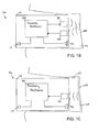
- FIG. 1B illustrates is a block diagram of a hearing assistance device with ear drum vibration processing according to one embodiment of the present subject matter.
- FIG. 1C is a block diagram of a hearing assistance device with ear drum vibration processing according to one embodiment of the present subject matter.
- FIG. 2 illustrates a hearing assistance device with an eardrum vibration detector according to one embodiment of the present subject matter.
- FIG. 3 illustrates a hearing assistance device with an eardrum vibration detector according to one embodiment of the present subject matter.
- FIG. 4 illustrates an end view of a hearing assistance device for sensing eardrum vibration according to one embodiment of the present subject matter.
- FIG. 5 illustrates an end view of a hearing assistance device for sensing eardrum vibration to estimate a sound field at the eardrum of a user according to one embodiment of the present subject matter.
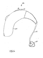
- FIG. 6 illustrates a hearing assistance device having a behind-the-ear (BTE) housing with ear drum vibration sensing to estimate a sound field at the eardrum of a user according to one embodiment of the present subject matter.
- BTE behind-the-ear
- FIG. 7A illustrates a block diagram of a hearing assistance device having a behind-the-ear (BTE) housing with ear drum vibration sensing to estimate a sound field at the eardrum of a user according to one embodiment of the present subject matter.
- BTE behind-the-ear
- FIG. 7B illustrates a block diagram of a hearing assistance device having a behind-the-ear (BTE) housing to estimate a sound field at the eardrum of a user according to one embodiment of the present subject matter.
- BTE behind-the-ear
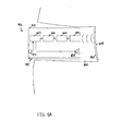
- FIG. 8A illustrates a hearing assistance device having magnetic wave detection electronics to estimate a sound field at the eardrum of a user according to one embodiment of the present subject matter.
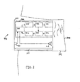
- FIG. 8B illustrates a block diagram of a hearing assistance device having a behind-the-ear (BTE) housing to estimate a sound field at the eardrum of a user according to one embodiment of the present subject matter.
- BTE behind-the-ear
- FIG. 9 illustrates a magnetic wave probe for detecting eardrum vibration of a user and estimating the sound field at the user's eardrum according to one embodiment of the present subject matter.
- FIG. 10 illustrates a flow diagram for estimating sound level and phase at the eardrum of a user according to one embodiment of the present subject matter.
- the sound field in an individual's ear canal is generally more uniform when subjected to low frequency sound because of the longer wavelength. Because of the uniformity, it is assumed that sound pressure levels and phase sensed near the eardrum provide an accurate measure of the sound pressure level and phase at the eardrum. However, the sound field becomes less uniform and more complex as the eardrum and ear canal are subjected to higher frequency sounds. It is risky and uncomfortable, to measure the sound pressure level at the eardrum by placing a sensor very close to the eardrum. Furthermore, it is difficult to predict the sound pressure level at the eardrum without placing a sensor very close to the eardrum.
- FIG. 1A illustrates a hearing assistance device with a vibration detector according to one embodiment of the present subject matter.
- the hearing assistance device 116 is adapted to be worn in a user's ear canal 109 and includes a housing 110 enclosing an eardrum vibration detector 100.
- the vibration detector senses vibration of the user's ear drum 108 to estimate sound pressure at or very close to the eardrum 108.
- the detector senses ear drum vibration using a magnetic media attached to the eardrum.
- the vibration detector senses ear drum vibration using detection signals emitted from the detector and reflected back to the detector by the user's ear drum, or tympanic membrane.
- the detector includes a laser source to emit a detection signal.
- the detector uses an ultrasonic emitter to emit a detection signal.
- FIG. 1B is a block diagram of a hearing assistance device with ear drum vibration processing according to one embodiment of the present subject matter.
- the hearing assistance device 116 is adapted to be worn in a user's ear canal 109 and includes a housing 110.
- the illustrated embodiment shows a transducer 101 for emitting a signal toward an eardrum and a sensor 102 for receiving emitted signals reflected off the eardrum 108.
- the transducer 101 and sensor 102 are connected to processing electronics 140.
- the processing electronics 140 include a processor, such as, a microprocessor or a digital signal processor (DSP), for example.
- the processing electronics include analog components, digital components or a combination of analog and digital components.
- the processing electronics determine sound pressure level and phase using the transducer 101 to generate, and the sensor 102 to receive, signals directed toward and reflected from an eardrum 108, or tympanic membrane, of a user.
- the transducer 101 is a laser transducer and the sensor 102 is an optical sensor.
- the laser transducer emits laser energy toward the eardrum and the optical sensor senses reflected laser energy from a user's eardrum.
- a laser transducer includes a laser diode.
- the transducer 101 is an ultrasonic emitter and the sensor 102 is an ultrasonic receiver.
- the processing electronics 140 include hearing assistance processing. The processing electronics 140 receive a signal from a microphone 111, process the signal to assist a user's hearing and plays the processed signal to the user's ear using a speaker 112.
- FIG. 1C is a block diagram of a hearing assistance device with ear drum vibration processing according to one embodiment of the present subject matter.
- the hearing assistance device 116 is adapted to be worn in a user's ear canal 109 and includes a housing 110.
- the illustrated embodiment shows a sensor 102 for generating signals corresponding to vibration of user's eardrum 108.
- the sensor is connected to processing electronics 140.
- the processing electronics 140 include a processor, such as, a microprocessor or a digital signal processor (DSP), for example.
- the processing electronics 140 include analog components, digital components or a combination of analog and digital components. It is understood that embodiments employing analog designs and analog-digital hybrid designs may be made which fall within the scope of the present subject matter.
- the processing electronics 140 determine sound pressure level and phase using the signal generated from the sensor 102.
- the signals indicative of eardrum vibration are generated by sensing changes in magnetic field strength using the sensor 102.
- a magnetic media 125 attached to the user's eardrum is used as a magnetic field source.
- the processing electronics 140 include hearing assistance processing.
- the processing electronics 140 receive a signal from a microphone 111, process the signal to assist a user's hearing and plays the processed signal to the user's ear using a speaker 112.
- FIG. 2 illustrates a hearing assistance device 216 with an eardrum vibration detector 200 according to one embodiment of the present subject matter.
- FIG. 2 shows a hearing assistance device 216 including a housing 210 adapted to be worn in the ear canal 209 of a user, such as an in-the-ear (ITE) housing or a completely-in-the-canal (CIC) housing.
- the illustrated housing 210 includes a vent 215.
- the hearing assistance device 216 includes a hearing assistance processor 213 connected to a microphone 211 and a speaker 214.
- the hearing assistance device 216 also includes an eardrum vibration detector including a transducer 201 and driver unit 203 connected to a processor 207 using a D/A converter 205.
- the illustrated eardrum vibration detector also includes a sensor 202 and demodulator 204 for receiving energy reflected from the eardrum 208 and generating a signal indicative of displacement, or vibration, of the eardrum 208.
- the transducer 201 is a laser based transducer and the sensor 202 is an optical sensor.
- the optical sensor receives laser energy, generated using the laser transducer, reflected from a user's eardrum to generate a signal indicative of eardrum vibration.
- the transducer 201 is an ultrasonic transducer and the sensor 202 is an ultrasonic receiver.
- the ultrasonic receiver senses ultrasonic acoustic energy, generated using the ultrasonic transducer, reflected from a user's eardrum to generate a signal indicative of eardrum vibration.
- the signal indicative of eardrum displacement, or the vibration signal is digitized using a A/D converter 206 and passed to the processor 207.
- the processor uses the digitized vibration signal to estimate the sound pressure level and phase at the eardrum 208.
- the estimates provide a basis for changing parameters in the hearing assistance device to improve performance of the hearing assistance device, increase hearing comfort of the user or a combination thereof.
- sound pressure level and phase estimates are electronically saved in the hearing assistance device for later analysis.
- the processing electronics store vibration signal samples and parameters associated with determining sound pressure level and phase estimates.
- FIG. 3 illustrates a hearing assistance device 316 with an eardrum vibration detector 300 according to one embodiment of the present subject matter.
- FIG. 3 shows a hearing assistance device 316 including a housing 310 adapted to be worn in the ear canal 309 of a user, such as an in-the-ear (ITE) housing or a completely-in-the-canal (CIC) housing.
- the illustrated housing 310 includes a vent 315.
- the hearing assistance device 316 includes a processor 307 connected to a microphone 311 and a speaker 314.
- the hearing assistance device 316 also includes an eardrum vibration detector including a transducer 301 and driver unit 303 connected to the processor 307 using a D/A converter 305.
- the illustrated eardrum vibration detector also includes a sensor 302 and demodulator 304 for receiving energy reflected from the eardrum 308 and generating a signal indicative of displacement, or vibration, of the eardrum 308.
- the transducer 301 is a laser transducer and the sensor 302 is a optical sensor. The optical sensor receives laser energy, generated using the laser based transducer, reflected from a user's eardrum to generate a signal indicative of eardrum vibration.
- the laser transducer includes a laser driver.
- the transducer 301 is an ultrasonic transducer and the sensor 302 is an ultrasonic receiver.
- the ultrasonic receiver senses ultrasonic acoustic energy, generated using the ultrasonic transducer, reflected from a user's eardrum to generate a signal indicative of eardrum vibration.
- the signal indicative of eardrum displacement, or the vibration signal is digitized using an A/D converter 306 and passed to the processor 307.
- the processor 307 includes processing for both sound pressure measurement and hearing assistance.
- the processor 307 uses the vibration signal to determine estimates of the sound pressure level and phase at the eardrum 308.
- the estimates provide a basis for changing parameters in the hearing assistance device to improve performance of the hearing assistance device, increase hearing comfort of the user or a combination thereof.
- sound pressure level and phase estimates are electronically saved in the hearing assistance device for later analysis.
- the ear drum vibration detector 300 and the hearing assistance processing are implemented using analog components, digital components or a combination of analog and digital components.
- FIG. 4 illustrates an end view of a hearing assistance device 416 that supports eardrum vibration sensing according to one embodiment of the present subject matter.
- FIG. 4 shows the end of the hearing assistance device housing 410 including a transducer opening 417, a sensor opening 418, a vent 415 and a speaker tube 414.
- FIG. 5 illustrates an end view of a hearing assistance device 516 that supports eardrum vibration sensing according to one embodiment of the present subject matter.
- FIG. 5 shows the end of the hearing assistance device housing including a transducer opening 517, a sensor opening 518, a vent 515 and a receiver tube 514.
- FIG. 6 illustrates a hearing assistance device 616 having a behind-the-ear (BTE) housing 620 that supports ear drum vibration sensing according to one embodiment of the present subject matter.
- BTE behind-the-ear
- FIG. 6 shows a BTE housing 620, including a microphone hood 619, an ear mold 610 and a cable assembly 624 connecting the earmold 610 to the BTE housing 620.
- the hearing assistance device includes a transducer and a sensor for detecting eardrum vibration.
- the cable assembly is adapted to transmit signals between the ear mold and the BTE housing for eardrum vibration detection and processing.
- the BTE housing 620 includes hearing assistance electronics, such as a microphone and a processor. In the illustrated embodiment of FIG.
- the ear mold includes a speaker and mounting apparatus to retain the cable assembly.
- the speaker emits acoustical signal at the user's eardrum.
- the hearing assistance electronics connect to the receiver in the ear mold using wires forming at least a portion of the cable 624 connecting the BTE housing 620 to the ear mold 610.
- FIG. 7A illustrates a block diagram of a hearing assistance device 716 having a behind-the-ear (BTE) housing 720 that supports ear drum vibration sensing according to one embodiment of the present subject matter.
- FIG. 7 shows a BTE housing 720, a cable assembly 724 and a second housing 710 including a speaker 712 to be worn in the ear canal 709 of a user.
- the second housing 710 is an ear mold, for example, or an ear bud.
- the second housing 710 includes a speaker 712 and fiber optics 723, 724 for emitting and receiving optical energy, such as laser light, for detecting eardrum vibration.
- the second housing 710 uses a cable assembly 724 to connect to the BTE housing 720.
- the cable assembly 724 includes fiber optics for transmitting laser energy between the second housing 710 and the BTE housing 720.
- the cable assembly 724 includes an emission fiber cable 723 for transmitting light from the laser source 701 to the second housing 710 and a reception fiber cable 724 for transmitting laser light from the second housing 710 to the sensor 702.
- the cable assembly 724 includes conductors 721 for connecting hearing assistance electronics located in the BTE housing 720 with a speaker 712 coupled to the second housing 710.
- the laser source includes a laser driver.
- the laser source includes a low level laser diode.
- the BTE housing 720 includes a microphone 711, processing electronics 740, a transducer 701 and a sensor 702.
- the processing electronics control detection and data analysis of signals indicative of eardrum vibration.
- the transducer is a laser light source 701 and the sensor is an optical sensor. Eardrum reflected laser light received using the optical sensor is used to detect eardrum vibration and for analysis and estimation of the sound field at the eardrum 708.
- the estimates provide a basis for changing parameters in the hearing assistance device to improve performance of the hearing assistance device, increase hearing comfort of the user or a combination thereof.
- sound pressure level and phase estimates are electronically saved in the hearing assistance device for later analysis.
- the laser source is enclosed in the ear mold and connected to the processing electronics in the BTE using conductors in the cable assembly.
- the sensor 702 includes a demodulator to decrease the processing load of the processing electronics 740.
- the demodulator is coupled to the processing electronics, the laser source and the sensor.
- the processing electronics include a digital signal processor (DSP).
- DSP digital signal processor
- FIG. 7B illustrates a block diagram of a hearing assistance device 716 having a behind-the-ear (BTE) housing 720 that supports ear drum vibration sensing according to one embodiment of the present subject matter.
- FIG. 7 shows a BTE housing 720, a cable assembly 724 and a second housing 710 including a speaker 712 to be worn in the ear canal 709 of a user.
- the second housing 710 is an ear mold, for example, or an ear bud.
- the second housing 710 includes a receiver 712, a transducer 701 and a sensor 702 emitting and receiving acoustic energy, such as ultrasonic sound waves, for detecting eardrum vibration.
- the second housing 710 uses a cable assembly 724 to connect to the BTE housing 720.
- the cable assembly 724 includes conductors for connecting the processing electronics 740 in the BTE housing to the speaker, transducer and the sensor.
- the BTE housing 720 includes a microphone 711 and processing electronics 740.
- the processing electronics 740 control detection and data analysis of signals indicative of eardrum vibration.
- the transducer 701 is an ultrasonic emitter and the sensor 702 is an ultrasonic receiver. Eardrum reflected ultrasonic sound received using the ultrasonic receiver is used to detect eardrum vibration and for analysis and estimation of the sound field at the eardrum 708.
- the sound field estimates provide a basis for changing parameters in the hearing assistance device to improve performance of the hearing assistance device, increase hearing comfort of the user or a combination thereof.
- sound pressure level and phase estimates are electronically saved in the hearing assistance device for later analysis.
- FIG. 8A illustrates a hearing assistance device 816 using magnetic wave detection electronics to estimate sound field at the eardrum 808 of a user according to one embodiment of the present subject matter.
- FIG. 8 shows a hearing assistance housing 810 positioned in the ear canal 809 of a user.
- the housing 810 includes a processor 807, hearing assistance electronics and eardrum vibration detection electronics.
- the hearing assistance electronics include a microphone 811 and a receiver 812.
- the hearing assistance device housing 810 includes a receiver tube 814 to direct sound from the receiver toward the user's eardrum.
- the housing 810 includes a vent 815 to minimize complete occlusion of the user's ear canal.
- the eardrum vibration detection electronics include a magnetic wave sensor 802, such as a coil, an amplification unit 804 and an A/D converter 806 for connecting the sensor output to the processor 807.
- the hearing assistance device includes more than one processor to process sound and estimate the sound field at the user's eardrum.
- a magnetic material 825 attached to the user's tympanic membrane, or eardrum 808.
- a thin magnet and a magnetic film are examples magnetic material used for attaching to the user's ear drum.
- the magnetic material 825 produces a magnetic field near the eardrum 808 of the user.
- the magnetic material 825 vibrates with the eardrum 808 and induces change in the magnetic field near the eardrum including the magnetic field in the ear canal 809.
- a change in magnetic field intensity will induce a signal in a coil present in and properly orientated to the magnetic field.
- the amplification electronics 804 include electronics to process the signal generated by the coil 802 in the changing magnetic field within a user's ear canal 809.
- FIG. 8B illustrates a block diagram of a hearing assistance device 816 having a behind-the-ear (BTE) housing 820 that supports ear drum vibration sensing according to one embodiment of the present subject matter.
- FIG. 8B shows a BTE housing 820, a cable assembly 824 and a second housing 810 including a speaker 812 to be worn in the ear canal 809 of a user.
- the second housing 810 is an ear mold, for example, or an ear bud.
- the second housing 810 includes a receiver 812 and a magnetic sensor 802 such, as a coil sensor, for detecting eardrum vibration.
- the second housing 810 uses a cable assembly 824 to connect to the BTE housing 820.
- the cable assembly 824 includes conductors for connecting devices enclosed in the second housing 810 to the processing electronics 740 in the BTE housing 820.
- the BTE housing 820 includes a microphone 811 and processing electronics 840.
- the processing electronics control detection and data analysis of signals received using the magnetic sensor 802 and indicative of eardrum vibration.
- the magnetic sensor 802 senses changes in a magnetic field established using magnetic media 825 attached to the user's eardrum 808. Signals indicative of eardrum vibration are used for analysis and estimation of the sound field at the eardrum 808.
- the sound field estimates provide a basis for changing parameters in the hearing assistance device to improve performance of the hearing assistance device, increase hearing comfort of the user or a combination thereof.
- sound pressure level and phase estimates are electronically saved in the hearing assistance device for later analysis.
- the processing electronics include one or more processors, including one or more DSPs.
- FIG. 9 illustrates a magnetic wave probe 930 for detecting eardrum vibration of a user and estimating the sound field at the user's eardrum according to one embodiment of the present subject matter.
- the probe 930 senses variation in magnetic field intensity using a coil 902 mechanically coupled to the probe 930.
- a magnetic material 925 such as a thin magnet or a magnetic film, attaches to the user's eardrum 908.
- the magnetic material 925 provides a magnetic field about the eardrum 908 of the user.
- the magnetic material 925 vibrates with the eardrum 908 and induces change in the magnetic field about the eardrum 908 including the magnetic field in the ear canal 909.
- a change in magnetic field intensity will induce a signal in a coil present and properly orientated in the magnetic field.
- the probe coil connects to amplification electronics 931.
- the amplification electronics 931 include electronics to process a signal generated by the coil in the changing magnetic field within the ear canal of a user.
- amplification electronics 931 connect the coil signal to an A/D converter 906 for digitizing the signal for processing using a connected, remote processor 932.
- the signal includes indications of the movement of the tympanic membrane in response to various acoustic waves.
- the processor uses the signal to estimate the sound field at the tympanic membrane.
- the estimates provide a basis for setting or changing parameters in a hearing assistance device to improve performance of the hearing assistance device, increase hearing comfort for the user of the device or a combination thereof.
- sound pressure level and phase estimates are electronically saved in the remote processor for later analysis.
- FIG. 10 illustrates a flow diagram 1050 for estimating sound pressure level and phase at the eardrum of a user according to the present subject matter.
- the method 1050 includes attaching a magnetic material to the user's tympanic membrane, or eardrum 1052, inserting a pickup coil sensor into user's ear canal adjacent the tympanic membrane 1054, capturing the coil signal indicative of movement or displacement of the tympanic membrane 1056, processing the signal indicative of movement or displacement of the tympanic membrane 1058 and determining the sound pressure level 1060 and phase 1062 at the tympanic membrane.
- hearing assistance devices including, but not limited to, hearing aids, such as behind-the-ear (BTE), in-the-ear (ITE), in-the-canal (ITC), or completely-in-the-canal (CIC) type hearing aids.
- BTE behind-the-ear
- ITE in-the-ear
- ITC in-the-canal
- CIC completely-in-the-canal
- hearing assistance devices may include devices that reside substantially behind the ear or over the ear.
- Such devices may include hearing aids with receivers associated with the electronics portion of the behind-the-ear device, or hearing aids of the type having receivers in-the-canal. It is understood that other hearing assistance devices not expressly stated herein may fall within the scope of the present subject matter.
Landscapes
- Health & Medical Sciences (AREA)
- Life Sciences & Earth Sciences (AREA)
- Otolaryngology (AREA)
- Engineering & Computer Science (AREA)
- Physics & Mathematics (AREA)
- General Health & Medical Sciences (AREA)
- Animal Behavior & Ethology (AREA)
- Veterinary Medicine (AREA)
- Heart & Thoracic Surgery (AREA)
- Medical Informatics (AREA)
- Molecular Biology (AREA)
- Surgery (AREA)
- Pathology (AREA)
- Biophysics (AREA)
- Public Health (AREA)
- Biomedical Technology (AREA)
- Audiology, Speech & Language Pathology (AREA)
- Acoustics & Sound (AREA)
- Signal Processing (AREA)
- Neurosurgery (AREA)
- Multimedia (AREA)
- Measuring Pulse, Heart Rate, Blood Pressure Or Blood Flow (AREA)
- Measuring And Recording Apparatus For Diagnosis (AREA)
- Details Of Audible-Bandwidth Transducers (AREA)
Abstract
Description
- This application relates generally to hearing assistance devices and more particularly to a system for estimating sound pressure level and phase at a wearer's eardrum by sensing eardrum vibration.
- Hearing assistance devices, including hearing aids, are electronic devices that provide signal processing functions such as wide dynamic range compression and output compression limiting control. In many hearing assistance devices these and other functions can be programmed to fit the requirements of individual users. Performance of a user's hearing assistance device, while the device is in the user's ear, is difficult to verify. The expense of measurement equipment, the time it takes to make the measurements, and the perceived complexity of the procedure, have all proven to be obstacles to widespread use of such measurements. However, such measurements may enable better programming of a user's hearing assistance device because each user's ear is different.
- This document provides method and apparatus for estimating the sound field at a user's tympanic membrane, or eardrum. One example provides a hearing assistance device, including a laser based eardrum vibration detector and processor for estimating the sound level and phase at the wearer's eardrum. One example provides a hearing assistance device, including an ultrasonic based eardrum vibration detector and processor for estimating the sound level and phase at the wearer's eardrum. The sound pressure estimates may be used to adjust the parameters of the hearing assistance device to provide for better performance of the device or comfort of the wearer. One example provides a method of estimating the sound field near a user's eardrum including attaching a magnetic material to the eardrum, inserting a probe with a pickup coil into the user's ear canal, capturing a signal indicative of eardrum movement using the pickup coil and processing the signal to provide an estimate of the sound level and phase at the eardrum.
- This Summary is an overview of some of the teachings of the present application and is not intended to be an exclusive or exhaustive treatment of the present subject matter. Further details about the present subject matter are found in the detailed description and the appended claims. The scope of the present invention is defined by the appended claims.
-
FIG. 1A illustrates a hearing assistance device with a vibration detector according to one embodiment of the present subject matter. -
FIG. 1B illustrates is a block diagram of a hearing assistance device with ear drum vibration processing according to one embodiment of the present subject matter. -
FIG. 1C is a block diagram of a hearing assistance device with ear drum vibration processing according to one embodiment of the present subject matter. -
FIG. 2 illustrates a hearing assistance device with an eardrum vibration detector according to one embodiment of the present subject matter. -
FIG. 3 illustrates a hearing assistance device with an eardrum vibration detector according to one embodiment of the present subject matter. -
FIG. 4 illustrates an end view of a hearing assistance device for sensing eardrum vibration according to one embodiment of the present subject matter. -
FIG. 5 illustrates an end view of a hearing assistance device for sensing eardrum vibration to estimate a sound field at the eardrum of a user according to one embodiment of the present subject matter. -
FIG. 6 illustrates a hearing assistance device having a behind-the-ear (BTE) housing with ear drum vibration sensing to estimate a sound field at the eardrum of a user according to one embodiment of the present subject matter. -
FIG. 7A illustrates a block diagram of a hearing assistance device having a behind-the-ear (BTE) housing with ear drum vibration sensing to estimate a sound field at the eardrum of a user according to one embodiment of the present subject matter. -
FIG. 7B illustrates a block diagram of a hearing assistance device having a behind-the-ear (BTE) housing to estimate a sound field at the eardrum of a user according to one embodiment of the present subject matter. -
FIG. 8A illustrates a hearing assistance device having magnetic wave detection electronics to estimate a sound field at the eardrum of a user according to one embodiment of the present subject matter. -
FIG. 8B illustrates a block diagram of a hearing assistance device having a behind-the-ear (BTE) housing to estimate a sound field at the eardrum of a user according to one embodiment of the present subject matter. -
FIG. 9 illustrates a magnetic wave probe for detecting eardrum vibration of a user and estimating the sound field at the user's eardrum according to one embodiment of the present subject matter. -
FIG. 10 illustrates a flow diagram for estimating sound level and phase at the eardrum of a user according to one embodiment of the present subject matter. - The following detailed description of the present invention refers to subject matter in the accompanying drawings which show, by way of illustration, specific aspects and embodiments in which the present subject matter may be practiced. These embodiments are described in sufficient detail to enable those skilled in the art to practice the present subject matter. References to "an", "one", or "various" embodiments in this disclosure are not necessarily to the same embodiment, and such references contemplate more than one embodiment. The following detailed description is, therefore, not to be taken in a limiting sense, and the scope is defined only by the appended claims, along with the full scope of legal equivalents to which such claims are entitled.
- The sound field in an individual's ear canal is generally more uniform when subjected to low frequency sound because of the longer wavelength. Because of the uniformity, it is assumed that sound pressure levels and phase sensed near the eardrum provide an accurate measure of the sound pressure level and phase at the eardrum. However, the sound field becomes less uniform and more complex as the eardrum and ear canal are subjected to higher frequency sounds. It is risky and uncomfortable, to measure the sound pressure level at the eardrum by placing a sensor very close to the eardrum. Furthermore, it is difficult to predict the sound pressure level at the eardrum without placing a sensor very close to the eardrum.
-
FIG. 1A illustrates a hearing assistance device with a vibration detector according to one embodiment of the present subject matter. Thehearing assistance device 116 is adapted to be worn in a user'sear canal 109 and includes ahousing 110 enclosing aneardrum vibration detector 100. The vibration detector senses vibration of the user'sear drum 108 to estimate sound pressure at or very close to theeardrum 108.
In various embodiments, the detector senses ear drum vibration using a magnetic media attached to the eardrum. In various embodiments, the vibration detector senses ear drum vibration using detection signals emitted from the detector and reflected back to the detector by the user's ear drum, or tympanic membrane. In various embodiments, the detector includes a laser source to emit a detection signal. In various embodiments, the detector uses an ultrasonic emitter to emit a detection signal. -
FIG. 1B is a block diagram of a hearing assistance device with ear drum vibration processing according to one embodiment of the present subject matter. Thehearing assistance device 116 is adapted to be worn in a user'sear canal 109 and includes ahousing 110. The illustrated embodiment shows atransducer 101 for emitting a signal toward an eardrum and asensor 102 for receiving emitted signals reflected off theeardrum 108. Thetransducer 101 andsensor 102 are connected toprocessing electronics 140. In various embodiments, theprocessing electronics 140 include a processor, such as, a microprocessor or a digital signal processor (DSP), for example. In various embodiments, the processing electronics include analog components, digital components or a combination of analog and digital components. It is understood that embodiments employing analog designs and analog-digital hybrid designs may be made which fall within the scope of the present subject matter. The processing electronics determine sound pressure level and phase using thetransducer 101 to generate, and thesensor 102 to receive, signals directed toward and reflected from aneardrum 108, or tympanic membrane, of a user. In various embodiments, thetransducer 101 is a laser transducer and thesensor 102 is an optical sensor. The laser transducer emits laser energy toward the eardrum and the optical sensor senses reflected laser energy from a user's eardrum.
In some embodiments, a laser transducer includes a laser diode. In various embodiments, thetransducer 101 is an ultrasonic emitter and thesensor 102 is an ultrasonic receiver. In various embodiments, theprocessing electronics 140 include hearing assistance processing. Theprocessing electronics 140 receive a signal from amicrophone 111, process the signal to assist a user's hearing and plays the processed signal to the user's ear using aspeaker 112. -
FIG. 1C is a block diagram of a hearing assistance device with ear drum vibration processing according to one embodiment of the present subject matter. Thehearing assistance device 116 is adapted to be worn in a user'sear canal 109 and includes ahousing 110. The illustrated embodiment shows asensor 102 for generating signals corresponding to vibration of user'seardrum 108. The sensor is connected to processingelectronics 140. In various embodiments, theprocessing electronics 140 include a processor, such as, a microprocessor or a digital signal processor (DSP), for example. In various embodiments, theprocessing electronics 140 include analog components, digital components or a combination of analog and digital components. It is understood that embodiments employing analog designs and analog-digital hybrid designs may be made which fall within the scope of the present subject matter. Theprocessing electronics 140 determine sound pressure level and phase using the signal generated from thesensor 102. The signals indicative of eardrum vibration are generated by sensing changes in magnetic field strength using thesensor 102. A magnetic media 125 attached to the user's eardrum is used as a magnetic field source. In various embodiments, theprocessing electronics 140 include hearing assistance processing. Theprocessing electronics 140 receive a signal from amicrophone 111, process the signal to assist a user's hearing and plays the processed signal to the user's ear using aspeaker 112. -
FIG. 2 illustrates ahearing assistance device 216 with aneardrum vibration detector 200 according to one embodiment of the present subject matter.FIG. 2 shows ahearing assistance device 216 including ahousing 210 adapted to be worn in theear canal 209 of a user, such as an in-the-ear (ITE) housing or a completely-in-the-canal (CIC) housing. The illustratedhousing 210 includes avent 215. Thehearing assistance device 216 includes ahearing assistance processor 213 connected to amicrophone 211 and a speaker 214. Thehearing assistance device 216 also includes an eardrum vibration detector including atransducer 201 anddriver unit 203 connected to aprocessor 207 using a D/A converter 205. The illustrated eardrum vibration detector also includes asensor 202 anddemodulator 204 for receiving energy reflected from theeardrum 208 and generating a signal indicative of displacement, or vibration, of theeardrum 208. In various embodiments, thetransducer 201 is a laser based transducer and thesensor 202 is an optical sensor. The optical sensor receives laser energy, generated using the laser transducer, reflected from a user's eardrum to generate a signal indicative of eardrum vibration. In various embodiments, thetransducer 201 is an ultrasonic transducer and thesensor 202 is an ultrasonic receiver. The ultrasonic receiver senses ultrasonic acoustic energy, generated using the ultrasonic transducer, reflected from a user's eardrum to generate a signal indicative of eardrum vibration. In the illustrated embodiment ofFIG. 2 , the signal indicative of eardrum displacement, or the vibration signal, is digitized using a A/D converter 206 and passed to theprocessor 207. The processor uses the digitized vibration signal to estimate the sound pressure level and phase at theeardrum 208. In various embodiments, the estimates provide a basis for changing parameters in the hearing assistance device to improve performance of the hearing assistance device, increase hearing comfort of the user or a combination thereof. In various embodiments, sound pressure level and phase estimates are electronically saved in the hearing assistance device for later analysis. In various embodiments, the processing electronics store vibration signal samples and parameters associated with determining sound pressure level and phase estimates. -
FIG. 3 illustrates ahearing assistance device 316 with aneardrum vibration detector 300 according to one embodiment of the present subject matter.FIG. 3 shows ahearing assistance device 316 including ahousing 310 adapted to be worn in theear canal 309 of a user, such as an in-the-ear (ITE) housing or a completely-in-the-canal (CIC) housing. The illustratedhousing 310 includes avent 315. Thehearing assistance device 316 includes aprocessor 307 connected to amicrophone 311 and a speaker 314. Thehearing assistance device 316 also includes an eardrum vibration detector including atransducer 301 anddriver unit 303 connected to theprocessor 307 using a D/A converter 305. The illustrated eardrum vibration detector also includes asensor 302 anddemodulator 304 for receiving energy reflected from the eardrum 308 and generating a signal indicative of displacement, or vibration, of the eardrum 308. In various embodiments, thetransducer 301 is a laser transducer and thesensor 302 is a optical sensor. The optical sensor receives laser energy, generated using the laser based transducer, reflected from a user's eardrum to generate a signal indicative of eardrum vibration. In some embodiments, the laser transducer includes a laser driver. In various embodiments, thetransducer 301 is an ultrasonic transducer and thesensor 302 is an ultrasonic receiver. The ultrasonic receiver senses ultrasonic acoustic energy, generated using the ultrasonic transducer, reflected from a user's eardrum to generate a signal indicative of eardrum vibration. In the illustrated embodiment ofFIG. 3 , the signal indicative of eardrum displacement, or the vibration signal, is digitized using an A/D converter 306 and passed to theprocessor 307. In the illustrated embodiment, theprocessor 307 includes processing for both sound pressure measurement and hearing assistance. Theprocessor 307 uses the vibration signal to determine estimates of the sound pressure level and phase at the eardrum 308. In various embodiments, the estimates provide a basis for changing parameters in the hearing assistance device to improve performance of the hearing assistance device, increase hearing comfort of the user or a combination thereof. In various embodiments, sound pressure level and phase estimates are electronically saved in the hearing assistance device for later analysis. In various embodiments, the eardrum vibration detector 300 and the hearing assistance processing are implemented using analog components, digital components or a combination of analog and digital components. -
FIG. 4 illustrates an end view of a hearing assistance device 416 that supports eardrum vibration sensing according to one embodiment of the present subject matter.FIG. 4 shows the end of the hearing assistance device housing 410 including atransducer opening 417, asensor opening 418, avent 415 and aspeaker tube 414. -
FIG. 5 illustrates an end view of ahearing assistance device 516 that supports eardrum vibration sensing according to one embodiment of the present subject matter.FIG. 5 shows the end of the hearing assistance device housing including atransducer opening 517, asensor opening 518, avent 515 and areceiver tube 514. -
FIG. 6 illustrates ahearing assistance device 616 having a behind-the-ear (BTE) housing 620 that supports ear drum vibration sensing according to one embodiment of the present subject matter.FIG. 6 shows a BTE housing 620, including amicrophone hood 619, an ear mold 610 and acable assembly 624 connecting the earmold 610 to the BTE housing 620. In various embodiments, the hearing assistance device includes a transducer and a sensor for detecting eardrum vibration. In various embodiments, the cable assembly is adapted to transmit signals between the ear mold and the BTE housing for eardrum vibration detection and processing. The BTE housing 620 includes hearing assistance electronics, such as a microphone and a processor. In the illustrated embodiment ofFIG. 6 , the ear mold includes a speaker and mounting apparatus to retain the cable assembly. The speaker emits acoustical signal at the user's eardrum. In various embodiments, the hearing assistance electronics connect to the receiver in the ear mold using wires forming at least a portion of thecable 624 connecting the BTE housing 620 to the ear mold 610. -
FIG. 7A illustrates a block diagram of ahearing assistance device 716 having a behind-the-ear (BTE)housing 720 that supports ear drum vibration sensing according to one embodiment of the present subject matter.FIG. 7 shows aBTE housing 720, acable assembly 724 and asecond housing 710 including aspeaker 712 to be worn in theear canal 709 of a user. In various embodiments, thesecond housing 710 is an ear mold, for example, or an ear bud. In the illustrated embodiment, thesecond housing 710 includes aspeaker 712 andfiber optics second housing 710 uses acable assembly 724 to connect to theBTE housing 720. In various embodiments, thecable assembly 724 includes fiber optics for transmitting laser energy between thesecond housing 710 and theBTE housing 720. In the illustrated embodiment, thecable assembly 724 includes anemission fiber cable 723 for transmitting light from thelaser source 701 to thesecond housing 710 and areception fiber cable 724 for transmitting laser light from thesecond housing 710 to thesensor 702. In various embodiments, thecable assembly 724 includesconductors 721 for connecting hearing assistance electronics located in theBTE housing 720 with aspeaker 712 coupled to thesecond housing 710. In some embodiments, the laser source includes a laser driver. IN various embodiments, the laser source includes a low level laser diode. - In the illustrated embodiment, the
BTE housing 720 includes amicrophone 711, processingelectronics 740, atransducer 701 and asensor 702. The processing electronics control detection and data analysis of signals indicative of eardrum vibration. In the illustrated embodiment, the transducer is alaser light source 701 and the sensor is an optical sensor. Eardrum reflected laser light received using the optical sensor is used to detect eardrum vibration and for analysis and estimation of the sound field at theeardrum 708. In various embodiments, the estimates provide a basis for changing parameters in the hearing assistance device to improve performance of the hearing assistance device, increase hearing comfort of the user or a combination thereof. In various embodiments, sound pressure level and phase estimates are electronically saved in the hearing assistance device for later analysis. In various embodiments, the laser source is enclosed in the ear mold and connected to the processing electronics in the BTE using conductors in the cable assembly. In various embodiments thesensor 702 includes a demodulator to decrease the processing load of theprocessing electronics 740. In some embodiments the demodulator is coupled to the processing electronics, the laser source and the sensor. In various embodiments the processing electronics include a digital signal processor (DSP). -
FIG. 7B illustrates a block diagram of ahearing assistance device 716 having a behind-the-ear (BTE)housing 720 that supports ear drum vibration sensing according to one embodiment of the present subject matter.FIG. 7 shows aBTE housing 720, acable assembly 724 and asecond housing 710 including aspeaker 712 to be worn in theear canal 709 of a user. In various embodiments, thesecond housing 710 is an ear mold, for example, or an ear bud. In the illustrated embodiment, thesecond housing 710 includes areceiver 712, atransducer 701 and asensor 702 emitting and receiving acoustic energy, such as ultrasonic sound waves, for detecting eardrum vibration. Thesecond housing 710 uses acable assembly 724 to connect to theBTE housing 720. In various embodiments, thecable assembly 724 includes conductors for connecting theprocessing electronics 740 in the BTE housing to the speaker, transducer and the sensor.
In the illustrated embodiment, theBTE housing 720 includes amicrophone 711 andprocessing electronics 740. Theprocessing electronics 740 control detection and data analysis of signals indicative of eardrum vibration. In the illustrated embodiment, thetransducer 701 is an ultrasonic emitter and thesensor 702 is an ultrasonic receiver. Eardrum reflected ultrasonic sound received using the ultrasonic receiver is used to detect eardrum vibration and for analysis and estimation of the sound field at theeardrum 708. In various embodiments, the sound field estimates provide a basis for changing parameters in the hearing assistance device to improve performance of the hearing assistance device, increase hearing comfort of the user or a combination thereof. In various embodiments, sound pressure level and phase estimates are electronically saved in the hearing assistance device for later analysis. -
FIG. 8A illustrates ahearing assistance device 816 using magnetic wave detection electronics to estimate sound field at theeardrum 808 of a user according to one embodiment of the present subject matter.FIG. 8 shows ahearing assistance housing 810 positioned in theear canal 809 of a user. Thehousing 810 includes aprocessor 807, hearing assistance electronics and eardrum vibration detection electronics. The hearing assistance electronics include a microphone 811 and areceiver 812. In the illustrated embodiment, the hearingassistance device housing 810 includes a receiver tube 814 to direct sound from the receiver toward the user's eardrum. In the illustrated embodiment, thehousing 810 includes avent 815 to minimize complete occlusion of the user's ear canal. - The eardrum vibration detection electronics include a
magnetic wave sensor 802, such as a coil, anamplification unit 804 and an A/D converter 806 for connecting the sensor output to theprocessor 807. In various embodiments, the hearing assistance device includes more than one processor to process sound and estimate the sound field at the user's eardrum. Also illustrated in the embodiment ofFIG. 8 , is amagnetic material 825 attached to the user's tympanic membrane, oreardrum 808. A thin magnet and a magnetic film are examples magnetic material used for attaching to the user's ear drum. - The
magnetic material 825 produces a magnetic field near theeardrum 808 of the user. Themagnetic material 825 vibrates with theeardrum 808 and induces change in the magnetic field near the eardrum including the magnetic field in theear canal 809. A change in magnetic field intensity will induce a signal in a coil present in and properly orientated to the magnetic field. In various embodiments, theamplification electronics 804 include electronics to process the signal generated by thecoil 802 in the changing magnetic field within a user'sear canal 809. -
FIG. 8B illustrates a block diagram of ahearing assistance device 816 having a behind-the-ear (BTE)housing 820 that supports ear drum vibration sensing according to one embodiment of the present subject matter.FIG. 8B shows aBTE housing 820, acable assembly 824 and asecond housing 810 including aspeaker 812 to be worn in theear canal 809 of a user. In various embodiments, thesecond housing 810 is an ear mold, for example, or an ear bud. In the illustrated embodiment, thesecond housing 810 includes areceiver 812 and amagnetic sensor 802 such, as a coil sensor, for detecting eardrum vibration. Thesecond housing 810 uses acable assembly 824 to connect to theBTE housing 820. Thecable assembly 824 includes conductors for connecting devices enclosed in thesecond housing 810 to theprocessing electronics 740 in theBTE housing 820. - In the illustrated embodiment, the
BTE housing 820 includes a microphone 811 andprocessing electronics 840. The processing electronics control detection and data analysis of signals received using themagnetic sensor 802 and indicative of eardrum vibration. Themagnetic sensor 802 senses changes in a magnetic field established usingmagnetic media 825 attached to the user'seardrum 808. Signals indicative of eardrum vibration are used for analysis and estimation of the sound field at theeardrum 808. In various embodiments, the sound field estimates provide a basis for changing parameters in the hearing assistance device to improve performance of the hearing assistance device, increase hearing comfort of the user or a combination thereof. In various embodiments, sound pressure level and phase estimates are electronically saved in the hearing assistance device for later analysis. In various embodiments the processing electronics include one or more processors, including one or more DSPs. -
FIG. 9 illustrates amagnetic wave probe 930 for detecting eardrum vibration of a user and estimating the sound field at the user's eardrum according to one embodiment of the present subject matter. Theprobe 930 senses variation in magnetic field intensity using acoil 902 mechanically coupled to theprobe 930. Amagnetic material 925, such as a thin magnet or a magnetic film, attaches to the user'seardrum 908. Themagnetic material 925 provides a magnetic field about theeardrum 908 of the user. Themagnetic material 925 vibrates with theeardrum 908 and induces change in the magnetic field about theeardrum 908 including the magnetic field in the ear canal 909.
A change in magnetic field intensity will induce a signal in a coil present and properly orientated in the magnetic field. In various embodiments, the probe coil connects to amplification electronics 931. In various embodiments, the amplification electronics 931 include electronics to process a signal generated by the coil in the changing magnetic field within the ear canal of a user. In the illustrated embodiment, amplification electronics 931 connect the coil signal to an A/D converter 906 for digitizing the signal for processing using a connected,remote processor 932. The signal includes indications of the movement of the tympanic membrane in response to various acoustic waves. The processor uses the signal to estimate the sound field at the tympanic membrane. In various embodiments, the estimates provide a basis for setting or changing parameters in a hearing assistance device to improve performance of the hearing assistance device, increase hearing comfort for the user of the device or a combination thereof. In various embodiments, sound pressure level and phase estimates are electronically saved in the remote processor for later analysis. -
FIG. 10 illustrates a flow diagram 1050 for estimating sound pressure level and phase at the eardrum of a user according to the present subject matter. Themethod 1050 includes attaching a magnetic material to the user's tympanic membrane, oreardrum 1052, inserting a pickup coil sensor into user's ear canal adjacent thetympanic membrane 1054, capturing the coil signal indicative of movement or displacement of thetympanic membrane 1056, processing the signal indicative of movement or displacement of the tympanic membrane 1058 and determining thesound pressure level 1060 andphase 1062 at the tympanic membrane. - The present subject matter includes hearing assistance devices, including, but not limited to, hearing aids, such as behind-the-ear (BTE), in-the-ear (ITE), in-the-canal (ITC), or completely-in-the-canal (CIC) type hearing aids. It is understood that behind-the-ear type hearing aids may include devices that reside substantially behind the ear or over the ear. Such devices may include hearing aids with receivers associated with the electronics portion of the behind-the-ear device, or hearing aids of the type having receivers in-the-canal. It is understood that other hearing assistance devices not expressly stated herein may fall within the scope of the present subject matter.
- This application is intended to cover adaptations and variations of the present subject matter. It is to be understood that the above description is intended to be illustrative, and not restrictive. The scope of the present subject matter should be determined with reference to the appended claims.
Claims (15)
- A device (116) for measuring sound pressure near a user's tympanic membrane, the device (116) comprising:a vibration detector (101,102) operable to detect vibrations of a user's tympanic membrane and generate a signal indicative of the detected movement of the tympanic membrane wherein the vibration detector (101, 102) comprises a source (101) operable to generate a signal which varies dependent upon the movement of the tympanic membrane and a sensor (102) operable to detect the signal generated by the source (101);a processor (140) adapted to estimate a value related to the movement of the tympanic membrane using the signal received from the sensor(102); anda housing (110) enclosing the vibration detector (101,102).
- The device of claim 1 wherein the vibration detector (101,102) comprises:a magnetic field source (101) coupled to the user's tympanic membrane;a sensor (102) adapted to detect the magnetic field source and generate a signal indicative of movement of the tympanic membrane.
- The device of claim 2, wherein the magnetic field source includes a thin magnet.
- The device of claim 2 or claim 3, wherein the magnetic field source includes a magnetic film.
- The device of claim 1 wherein the vibration detector (101,102) comprises:a laser source (101) adapted to project a beam of laser energy at a user's tympanic membrane; anda sensor (102) for receiving reflected laser energy directed at the tympanic membrane.
- The device of claim 1 wherein the vibration detector (101,102) comprises:an ultrasonic wave source (101) adapted to project ultrasonic waves at a user's tympanic membrane;an ultrasonic sensor (102) for receiving reflected ultrasonic waves directed at the tympanic membrane.
- The device of any of claims 1-6, wherein the value includes a sound pressure level or a sound pressure phase.
- The device of any of claims 1-7, further comprising a microphone (111) coupled to the processor (140).
- The device of any of claims 1-8, further comprising a speaker (112) coupled to the processor (140).
- A method of estimating sound pressure in an ear canal of a user, the method comprising:providing a vibration detector (101,102) operable to detect vibration of the tympanic membrane of a user's ear wherein the vibration detector (101, 102) comprises a source (101) operable to generate a signal which varies dependent upon the movement of the tympanic membrane and a sensor (102) operable to detect the signal generated by the source (101);detecting movement of the tympanic membrane using the vibration detector (101,102);generating a vibration signal indicative of the detected movement of the tympanic membrane; andestimating a value related to sound in the ear canal using the vibration signal.
- The method of claim 10 wherein providing a vibration detector (101,102) operable to detect vibration of the tympanic membrane of a user's ear comprises providing a magnetic field source (101) disposed on user's tympanic membrane and wherein detecting movement of the tympanic membrane comprises detecting magnetic field variations arising due to movement of the magnetic field source using a magnetic sensor (102) disposed in the ear canal.
- The method of claim 10 wherein providing a vibration detector (101,102) operable to detect vibration of the tympanic membrane of a user's ear comprises providing a laser source (101) adapted to project a beam of laser energy at a user's tympanic membrane, and wherein detecting movement of the tympanic membrane comprises detecting variations in laser energy reflected by the tympanic membrane arising due to movement of the tympanic membrane.
- The method of claim 10 wherein providing a vibration detector (101,102) operable to detect vibration of the tympanic membrane of a user's ear comprises providing a ultrasound source (101) adapted to project ultrasonic waves at a user's tympanic membrane, and wherein detecting movement of the tympanic membrane comprises detecting variations in ultrasonic waves reflected by the tympanic membrane arising due to movement of the tympanic membrane.
- The method of any of claims 10-13, wherein estimating a value includes estimating sound pressure level and/or sound pressure phase near the tympanic membrane.
- The method of any of claims 10-14, wherein estimating a value includes adjusting a hearing assistance device parameter.
Applications Claiming Priority (1)
| Application Number | Priority Date | Filing Date | Title |
|---|---|---|---|
| US12/130,764 US20090299215A1 (en) | 2008-05-30 | 2008-05-30 | Measurement of sound pressure level and phase at eardrum by sensing eardrum vibration |
Publications (2)
| Publication Number | Publication Date |
|---|---|
| EP2129169A2 true EP2129169A2 (en) | 2009-12-02 |
| EP2129169A3 EP2129169A3 (en) | 2013-04-03 |
Family
ID=41066161
Family Applications (1)
| Application Number | Title | Priority Date | Filing Date |
|---|---|---|---|
| EP09161477A Withdrawn EP2129169A3 (en) | 2008-05-30 | 2009-05-29 | Measurement of sound pressure level and phase at eardrum by sensing eardrum vibration |
Country Status (2)
| Country | Link |
|---|---|
| US (2) | US20090299215A1 (en) |
| EP (1) | EP2129169A3 (en) |
Cited By (3)
| Publication number | Priority date | Publication date | Assignee | Title |
|---|---|---|---|---|
| CN103988485A (en) * | 2012-05-18 | 2014-08-13 | 京瓷株式会社 | Measuring equipment, measuring system and measuring method |
| EP2613562A3 (en) * | 2012-01-06 | 2017-05-03 | Sony Mobile Communications AB | Ultrasonic sound reproduction on eardrum |
| EP3451700A1 (en) | 2017-08-28 | 2019-03-06 | "BOCORE" GmbH | Device for reproducing an audio signal |
Families Citing this family (50)
| Publication number | Priority date | Publication date | Assignee | Title |
|---|---|---|---|---|
| US8652040B2 (en) | 2006-12-19 | 2014-02-18 | Valencell, Inc. | Telemetric apparatus for health and environmental monitoring |
| US8157730B2 (en) | 2006-12-19 | 2012-04-17 | Valencell, Inc. | Physiological and environmental monitoring systems and methods |
| US8452021B2 (en) | 2007-04-17 | 2013-05-28 | Starkey Laboratories, Inc. | Real ear measurement system using thin tube |
| US8251903B2 (en) | 2007-10-25 | 2012-08-28 | Valencell, Inc. | Noninvasive physiological analysis using excitation-sensor modules and related devices and methods |
| AU2009201227B2 (en) * | 2008-03-31 | 2011-07-07 | Starkey Laboratories, Inc. | Methods and apparatus for real-ear measurements for receiver-in-canal devices |
| EP2107831A3 (en) * | 2008-03-31 | 2010-12-29 | Starkey Laboratories, Inc. | Real ear measurement adaptor with internal sound conduit |
| US20090299215A1 (en) * | 2008-05-30 | 2009-12-03 | Starkey Laboratories, Inc. | Measurement of sound pressure level and phase at eardrum by sensing eardrum vibration |
| WO2010016925A1 (en) * | 2008-08-08 | 2010-02-11 | Starkey Laboratories, Inc. | System for measuring sound pressure level |
| US8542841B2 (en) * | 2009-01-12 | 2013-09-24 | Starkey Laboratories, Inc. | Method to estimate the sound pressure level at eardrum using measurements away from the eardrum |
| US8788002B2 (en) | 2009-02-25 | 2014-07-22 | Valencell, Inc. | Light-guiding devices and monitoring devices incorporating same |
| US9750462B2 (en) | 2009-02-25 | 2017-09-05 | Valencell, Inc. | Monitoring apparatus and methods for measuring physiological and/or environmental conditions |
| US8700111B2 (en) * | 2009-02-25 | 2014-04-15 | Valencell, Inc. | Light-guiding devices and monitoring devices incorporating same |
| US9107015B2 (en) * | 2009-03-27 | 2015-08-11 | Starkey Laboratories, Inc. | System for automatic fitting using real ear measurement |
| WO2011130490A2 (en) | 2010-04-15 | 2011-10-20 | Med-El Elektromedizinische Geraete Gmbh | Transducer for stapedius monitoring |
| US8888701B2 (en) | 2011-01-27 | 2014-11-18 | Valencell, Inc. | Apparatus and methods for monitoring physiological data during environmental interference |
| US9427191B2 (en) | 2011-07-25 | 2016-08-30 | Valencell, Inc. | Apparatus and methods for estimating time-state physiological parameters |
| EP3222210B1 (en) | 2011-08-02 | 2024-09-25 | Yukka Magic LLC | Systems and methods for variable filter adjustment by heart rate metric feedback |
| EP2663095B1 (en) * | 2012-05-07 | 2015-11-18 | Starkey Laboratories, Inc. | Hearing aid with distributed processing in ear piece |
| WO2014116942A2 (en) | 2013-01-28 | 2014-07-31 | Valencell, Inc. | Physiological monitoring devices having sensing elements decoupled from body motion |
| US9039639B2 (en) | 2013-06-28 | 2015-05-26 | Gbs Ventures Llc | External ear canal pressure regulation system |
| US12396892B2 (en) | 2013-06-28 | 2025-08-26 | Nocira, Llc | External ear canal pressure regulation device |
| US10251790B2 (en) | 2013-06-28 | 2019-04-09 | Nocira, Llc | Method for external ear canal pressure regulation to alleviate disorder symptoms |
| EP3214857A1 (en) * | 2013-09-17 | 2017-09-06 | Oticon A/s | A hearing assistance device comprising an input transducer system |
| US20160029898A1 (en) | 2014-07-30 | 2016-02-04 | Valencell, Inc. | Physiological Monitoring Devices and Methods Using Optical Sensors |
| US10536768B2 (en) | 2014-08-06 | 2020-01-14 | Valencell, Inc. | Optical physiological sensor modules with reduced signal noise |
| JP6254501B2 (en) * | 2014-09-08 | 2017-12-27 | 京セラ株式会社 | Biological information measuring device |
| US9794653B2 (en) | 2014-09-27 | 2017-10-17 | Valencell, Inc. | Methods and apparatus for improving signal quality in wearable biometric monitoring devices |
| US9843853B2 (en) | 2015-08-29 | 2017-12-12 | Bragi GmbH | Power control for battery powered personal area network device system and method |
| US10104458B2 (en) | 2015-10-20 | 2018-10-16 | Bragi GmbH | Enhanced biometric control systems for detection of emergency events system and method |
| US10945618B2 (en) | 2015-10-23 | 2021-03-16 | Valencell, Inc. | Physiological monitoring devices and methods for noise reduction in physiological signals based on subject activity type |
| EP3344127A4 (en) | 2015-10-23 | 2018-07-25 | Valencell, Inc. | Physiological monitoring devices and methods that identify subject activity type |
| US10085082B2 (en) | 2016-03-11 | 2018-09-25 | Bragi GmbH | Earpiece with GPS receiver |
| US10052065B2 (en) | 2016-03-23 | 2018-08-21 | Bragi GmbH | Earpiece life monitor with capability of automatic notification system and method |
| US10201309B2 (en) | 2016-07-06 | 2019-02-12 | Bragi GmbH | Detection of physiological data using radar/lidar of wireless earpieces |
| US10966662B2 (en) | 2016-07-08 | 2021-04-06 | Valencell, Inc. | Motion-dependent averaging for physiological metric estimating systems and methods |
| US10760566B2 (en) | 2016-07-22 | 2020-09-01 | Nocira, Llc | Magnetically driven pressure generator |
| US10062373B2 (en) | 2016-11-03 | 2018-08-28 | Bragi GmbH | Selective audio isolation from body generated sound system and method |
| US10058282B2 (en) | 2016-11-04 | 2018-08-28 | Bragi GmbH | Manual operation assistance with earpiece with 3D sound cues |
| US10063957B2 (en) | 2016-11-04 | 2018-08-28 | Bragi GmbH | Earpiece with source selection within ambient environment |
| IL267082B2 (en) | 2016-12-06 | 2024-09-01 | Nocira Llc | Systems and methods for treating neurological disorders |
| EP3585335B1 (en) | 2017-02-27 | 2024-05-08 | Nocira, LLC | Ear pumps |
| US10344960B2 (en) | 2017-09-19 | 2019-07-09 | Bragi GmbH | Wireless earpiece controlled medical headlight |
| US11272367B2 (en) | 2017-09-20 | 2022-03-08 | Bragi GmbH | Wireless earpieces for hub communications |
| WO2019246456A1 (en) | 2018-06-22 | 2019-12-26 | Nocira, Llc | Systems and methods for treating neurological disorders |
| EP3672272A1 (en) | 2018-12-17 | 2020-06-24 | GN Hearing A/S | Earpiece for a hearing device |
| US12042328B2 (en) * | 2018-12-19 | 2024-07-23 | Nec Corporation | Information processing device, wearable device, information processing method, and storage medium |
| US10720141B1 (en) | 2018-12-28 | 2020-07-21 | X Development Llc | Tympanic membrane measurement |
| WO2020159075A1 (en) | 2019-01-28 | 2020-08-06 | 경북대학교 산학협력단 | Optical interference-based auditory function measuring device and method |
| CN114467311A (en) * | 2020-07-24 | 2022-05-10 | 华为技术有限公司 | Active noise reduction method and device |
| US12521053B2 (en) * | 2022-01-05 | 2026-01-13 | Tdk Corporation | Methods and devices for electromagnetic measurements from ear cavity |
Family Cites Families (21)
| Publication number | Priority date | Publication date | Assignee | Title |
|---|---|---|---|---|
| DE2155853C3 (en) * | 1971-11-10 | 1975-02-06 | Lothar Ulrich Eberhard Dr. 7410 Reutlingen Kohlloeffel | Device for visualizing the vibrating surface areas of the eardrum of humans or animals |
| US5699809A (en) * | 1985-11-17 | 1997-12-23 | Mdi Instruments, Inc. | Device and process for generating and measuring the shape of an acoustic reflectance curve of an ear |
| US4809708A (en) * | 1987-08-12 | 1989-03-07 | Nicolet Instrument Corporation | Method and apparatus for real bar measurements |
| DK45889D0 (en) * | 1989-02-01 | 1989-02-01 | Medicoteknisk Inst | PROCEDURE FOR HEARING ADJUSTMENT |
| US5259032A (en) * | 1990-11-07 | 1993-11-02 | Resound Corporation | contact transducer assembly for hearing devices |
| JPH06506337A (en) * | 1991-04-01 | 1994-07-14 | リザウンド コーポレイション | Discreet communication method using remote electromagnetic drive |
| US5868682A (en) * | 1995-01-26 | 1999-02-09 | Mdi Instruments, Inc. | Device and process for generating and measuring the shape of an acoustic reflectance curve of an ear |
| US5711308A (en) * | 1995-06-07 | 1998-01-27 | Interval Research Corporation | Wearable apparatus for measuring displacement of an in vivo tympanum and methods and systems for use therewith |
| DE19527108A1 (en) * | 1995-07-25 | 1997-01-30 | Hans Peter Prof Dr Med Zenner | Determination of hearing data |
| US5897494A (en) * | 1997-01-31 | 1999-04-27 | The Board Of Trustees Of The University Of Arkansas | Vibrometer |
| US6940989B1 (en) * | 1999-12-30 | 2005-09-06 | Insound Medical, Inc. | Direct tympanic drive via a floating filament assembly |
| US7248713B2 (en) * | 2000-09-11 | 2007-07-24 | Micro Bar Technology, Inc. | Integrated automatic telephone switch |
| US7024010B2 (en) * | 2003-05-19 | 2006-04-04 | Adaptive Technologies, Inc. | Electronic earplug for monitoring and reducing wideband noise at the tympanic membrane |
| US6997864B2 (en) * | 2003-11-03 | 2006-02-14 | Otologics, Llc | Method for obtaining diagnostic information relating to a patient having an implanted transducer |
| US7668325B2 (en) * | 2005-05-03 | 2010-02-23 | Earlens Corporation | Hearing system having an open chamber for housing components and reducing the occlusion effect |
| WO2006101935A2 (en) * | 2005-03-16 | 2006-09-28 | Sonicom, Inc. | Test battery system and method for assessment of auditory function |
| EP1708544B1 (en) * | 2005-03-29 | 2015-07-15 | Oticon A/S | System and method for measuring vent effects in a hearing aid |
| DE602006011375D1 (en) * | 2006-08-07 | 2010-02-04 | Widex As | HEARING DEVICE, METHOD FOR IN-SITU-OCKLUSION EFFECT AND METHOD FOR DIRECT SQUARE MEASUREMENT AND OPENING SIZE DETERMINATION |
| US20090299215A1 (en) * | 2008-05-30 | 2009-12-03 | Starkey Laboratories, Inc. | Measurement of sound pressure level and phase at eardrum by sensing eardrum vibration |
| WO2010016925A1 (en) * | 2008-08-08 | 2010-02-11 | Starkey Laboratories, Inc. | System for measuring sound pressure level |
| US8542841B2 (en) * | 2009-01-12 | 2013-09-24 | Starkey Laboratories, Inc. | Method to estimate the sound pressure level at eardrum using measurements away from the eardrum |
-
2008
- 2008-05-30 US US12/130,764 patent/US20090299215A1/en not_active Abandoned
-
2009
- 2009-05-29 EP EP09161477A patent/EP2129169A3/en not_active Withdrawn
-
2010
- 2010-12-29 US US12/980,745 patent/US20110098551A1/en not_active Abandoned
Cited By (9)
| Publication number | Priority date | Publication date | Assignee | Title |
|---|---|---|---|---|
| EP2613562A3 (en) * | 2012-01-06 | 2017-05-03 | Sony Mobile Communications AB | Ultrasonic sound reproduction on eardrum |
| CN103988485A (en) * | 2012-05-18 | 2014-08-13 | 京瓷株式会社 | Measuring equipment, measuring system and measuring method |
| EP2879406A3 (en) * | 2012-05-18 | 2015-06-17 | Kyocera Corporation | Measuring apparatus, measuring system and measuring method |
| EP2884769A3 (en) * | 2012-05-18 | 2015-06-24 | Kyocera Corporation | Measuring apparatus, measuring system and measuring method |
| CN103988485B (en) * | 2012-05-18 | 2017-03-15 | 京瓷株式会社 | Measuring equipment, measuring system and measuring method |
| US9618385B2 (en) | 2012-05-18 | 2017-04-11 | Kyocera Corporation | Measuring apparatus, measuring system and measuring method |
| US9866980B2 (en) | 2012-05-18 | 2018-01-09 | Kyocera Corporation | Measuring apparatus, measuring system and measuring method |
| EP3451700A1 (en) | 2017-08-28 | 2019-03-06 | "BOCORE" GmbH | Device for reproducing an audio signal |
| WO2019042953A1 (en) | 2017-08-28 | 2019-03-07 | "Bocore" Gmbh | DEVICE FOR PLAYING AN AUDIO SIGNAL |
Also Published As
| Publication number | Publication date |
|---|---|
| US20110098551A1 (en) | 2011-04-28 |
| US20090299215A1 (en) | 2009-12-03 |
| EP2129169A3 (en) | 2013-04-03 |
Similar Documents
| Publication | Publication Date | Title |
|---|---|---|
| US20090299215A1 (en) | Measurement of sound pressure level and phase at eardrum by sensing eardrum vibration | |
| US8542841B2 (en) | Method to estimate the sound pressure level at eardrum using measurements away from the eardrum | |
| US9473858B2 (en) | Hearing device | |
| JP5325999B2 (en) | System, method and hearing aid for measuring the wearing occlusion effect | |
| US8879763B2 (en) | Method and apparatus for detecting user activities from within a hearing assistance device using a vibration sensor | |
| DK1708544T3 (en) | System and method for measuring ventilation effects in a hearing aid | |
| EP2234414A2 (en) | System for automatic fitting using real ear measurement | |
| US20120114157A1 (en) | Method and hearing aid for determining moisture and computer program product implementing the method | |
| US20090238387A1 (en) | Method for actively reducing occlusion comprising plausibility check and corresponding hearing apparatus | |
| US9693159B2 (en) | Method of fitting a hearing aid and a hearing aid | |
| US8130992B2 (en) | Hearing aid with anti-feedback | |
| JP2019080304A (en) | Hearing device associated with method of estimating ear shape | |
| US9843873B2 (en) | Hearing device | |
| US20120114156A1 (en) | Hearing aid and method for operating a hearing aid with a humidity sensor | |
| US10575105B2 (en) | Method for characterizing a receiver in a hearing device, hearing device and test apparatus for a hearing device | |
| US20110228960A1 (en) | Hearing device and method for setting the hearing device for feedback-reduced operation | |
| US20100195856A1 (en) | Method for determining the acoustic feedback behavior of a hearing device on the basis of geometric data of an ear | |
| US20230363649A1 (en) | Headset | |
| JP2000069596A (en) | Earplug type electroacoustic transducer |
Legal Events
| Date | Code | Title | Description |
|---|---|---|---|
| PUAI | Public reference made under article 153(3) epc to a published international application that has entered the european phase |
Free format text: ORIGINAL CODE: 0009012 |
|
| 17P | Request for examination filed |
Effective date: 20090529 |
|
| AK | Designated contracting states |
Kind code of ref document: A2 Designated state(s): AT BE BG CH CY CZ DE DK EE ES FI FR GB GR HR HU IE IS IT LI LT LU LV MC MK MT NL NO PL PT RO SE SI SK TR |
|
| PUAL | Search report despatched |
Free format text: ORIGINAL CODE: 0009013 |
|
| AK | Designated contracting states |
Kind code of ref document: A3 Designated state(s): AT BE BG CH CY CZ DE DK EE ES FI FR GB GR HR HU IE IS IT LI LT LU LV MC MK MT NL NO PL PT RO SE SI SK TR |
|
| RIC1 | Information provided on ipc code assigned before grant |
Ipc: H04R 25/00 20060101AFI20130225BHEP Ipc: A61B 5/12 20060101ALI20130225BHEP |
|
| 17Q | First examination report despatched |
Effective date: 20140630 |
|
| STAA | Information on the status of an ep patent application or granted ep patent |
Free format text: STATUS: THE APPLICATION IS DEEMED TO BE WITHDRAWN |
|
| 18D | Application deemed to be withdrawn |
Effective date: 20141111 |