EP2128925A1 - Planar antenna and electronic device - Google Patents
Planar antenna and electronic device Download PDFInfo
- Publication number
- EP2128925A1 EP2128925A1 EP09160450A EP09160450A EP2128925A1 EP 2128925 A1 EP2128925 A1 EP 2128925A1 EP 09160450 A EP09160450 A EP 09160450A EP 09160450 A EP09160450 A EP 09160450A EP 2128925 A1 EP2128925 A1 EP 2128925A1
- Authority
- EP
- European Patent Office
- Prior art keywords
- antenna
- planar
- antenna element
- ground portion
- planar antenna
- Prior art date
- Legal status (The legal status is an assumption and is not a legal conclusion. Google has not performed a legal analysis and makes no representation as to the accuracy of the status listed.)
- Granted
Links
Images


Classifications
-
- H—ELECTRICITY
- H01—ELECTRIC ELEMENTS
- H01Q—ANTENNAS, i.e. RADIO AERIALS
- H01Q9/00—Electrically-short antennas having dimensions not more than twice the operating wavelength and consisting of conductive active radiating elements
- H01Q9/04—Resonant antennas
- H01Q9/30—Resonant antennas with feed to end of elongated active element, e.g. unipole
- H01Q9/42—Resonant antennas with feed to end of elongated active element, e.g. unipole with folded element, the folded parts being spaced apart a small fraction of the operating wavelength
-
- H—ELECTRICITY
- H01—ELECTRIC ELEMENTS
- H01Q—ANTENNAS, i.e. RADIO AERIALS
- H01Q1/00—Details of, or arrangements associated with, antennas
- H01Q1/12—Supports; Mounting means
- H01Q1/22—Supports; Mounting means by structural association with other equipment or articles
- H01Q1/2208—Supports; Mounting means by structural association with other equipment or articles associated with components used in interrogation type services, i.e. in systems for information exchange between an interrogator/reader and a tag/transponder, e.g. in Radio Frequency Identification [RFID] systems
- H01Q1/2216—Supports; Mounting means by structural association with other equipment or articles associated with components used in interrogation type services, i.e. in systems for information exchange between an interrogator/reader and a tag/transponder, e.g. in Radio Frequency Identification [RFID] systems used in interrogator/reader equipment
-
- H—ELECTRICITY
- H01—ELECTRIC ELEMENTS
- H01Q—ANTENNAS, i.e. RADIO AERIALS
- H01Q1/00—Details of, or arrangements associated with, antennas
- H01Q1/12—Supports; Mounting means
- H01Q1/22—Supports; Mounting means by structural association with other equipment or articles
- H01Q1/24—Supports; Mounting means by structural association with other equipment or articles with receiving set
- H01Q1/241—Supports; Mounting means by structural association with other equipment or articles with receiving set used in mobile communications, e.g. GSM
- H01Q1/242—Supports; Mounting means by structural association with other equipment or articles with receiving set used in mobile communications, e.g. GSM specially adapted for hand-held use
- H01Q1/243—Supports; Mounting means by structural association with other equipment or articles with receiving set used in mobile communications, e.g. GSM specially adapted for hand-held use with built-in antennas
-
- H—ELECTRICITY
- H01—ELECTRIC ELEMENTS
- H01Q—ANTENNAS, i.e. RADIO AERIALS
- H01Q5/00—Arrangements for simultaneous operation of antennas on two or more different wavebands, e.g. dual-band or multi-band arrangements
- H01Q5/30—Arrangements for providing operation on different wavebands
- H01Q5/307—Individual or coupled radiating elements, each element being fed in an unspecified way
- H01Q5/342—Individual or coupled radiating elements, each element being fed in an unspecified way for different propagation modes
- H01Q5/357—Individual or coupled radiating elements, each element being fed in an unspecified way for different propagation modes using a single feed point
- H01Q5/364—Creating multiple current paths
-
- H—ELECTRICITY
- H01—ELECTRIC ELEMENTS
- H01Q—ANTENNAS, i.e. RADIO AERIALS
- H01Q9/00—Electrically-short antennas having dimensions not more than twice the operating wavelength and consisting of conductive active radiating elements
- H01Q9/04—Resonant antennas
- H01Q9/30—Resonant antennas with feed to end of elongated active element, e.g. unipole
- H01Q9/40—Element having extended radiating surface
Definitions
- the present invention relates to a planar antenna and an electronic device.
- a planar multiband antenna has been proposed as an antenna for wireless communication which is provided in a portable device (see JP-A-2007-13596 , for example). Since the multiband antenna has a planar shape, it can easily be stored in the portable device. Moreover, wireless communications in a plurality of resonance frequency bands can be performed.
- An inversed F-shaped antenna having an inversed F-shaped antenna element has also been known as an antenna for wireless communication. Furthermore, a multiband inversed F-shaped antenna has also been proposed (see JP-A-10-93332 , for example).
- the conventional multiband inversed F-shaped antenna has a plurality of rectangular antenna elements, and the band width of each resonance frequency is structurally narrow.
- the conventional multiband inversed F-shaped antenna has a cubic resonance structure, a storage space for the antenna has to be large.
- a main object of the present invention to extend the band width of a resonance frequency band in a multiband antenna and also reduce a storage space for the antenna.
- a planar antenna including: a film formed of a planar insulating material; an antenna portion which is a planar conductor on the film; and a ground portion which is a conductor to be grounded, wherein the antenna portion includes: at least one first short stub; a first antenna element which is connected to the ground portion through the at least one first short stub and whose shape has such an angle that a distance between the first antenna element and the ground portion increases with increasing distance from a feeding point along the ground portion, the feeding point being provided between the first antenna element and the ground portion; a second short stub; and a second antenna element which is connected to the first antenna element through the second short stub.
- a planar antenna including: a film formed of a planar insulating material; an antenna portion which is a planar conductor on the film; and a ground portion which is a conductor to be grounded, wherein the antenna portion includes: at least one first short stub; a first antenna element which is connected to the ground portion through the at least one first short stub, a feeding point being provided between the first antenna element and the ground portion; a plurality of second short stubs; and a second antenna element which is connected to the first antenna element through the second short stubs.
- the band width of each of the plurality of resonance frequency bands can be extended in the multiband antenna, and a storage space for the antenna can be reduced.
- the band width of the resonance frequency band corresponding to a second antenna element can be extended in the multiband antenna, and also a storage space for the antenna can be reduced.
- Fig. 1 is a front view showing a front-side configuration of a handy terminal 1 according to an embodiment.
- Fig. 2A is a perspective view showing a perspective configuration of the back side of the handy terminal 1
- Fig. 2B is a perspective view showing a perspective configuration of one side of the handy terminal 1
- Fig. 2C is a perspective view showing a perspective configuration of the top side of the handy terminal 1.
- the handy terminal 1 as an electronic device is a portable terminal having functions such as input of information through a user's operation, storage of information, bar-code scanning, etc.
- the handy terminal 1 has ha as a function of performing wireless communication with an external device through an access point according to the wireless LAN (Local Area Network) system, and a cellular phone communication function based on the GSM (Global System for Mobile Communications) system.
- wireless LAN Local Area Network
- GSM Global System for Mobile Communications
- the electronic device of this embodiment is not limited to the handy terminal 1, and it may contain electronic devices such as PDA (Personal Digital Assistance), a cellular phone, a portable communication terminal, a portable device having a wireless communication function such as a portable computer, etc.
- PDA Personal Digital Assistance
- the handy terminal 1 has a display unit 14, a trigger key 3A, various kinds of keys 3C, etc. on the front surface of a case 2.
- the handy terminal 1 has trigger keys 3B on both the side surfaces of the case 2.
- the trigger keys 3A, 3B serve to accept light irradiation of a scanning unit 10 described later and a trigger operation input of bar-code scanning.
- the various kinds of keys 3C are character input keys of numerals, etc., and function keys for accepting the input of various kinds of functions such as mode switching, etc.
- the handy terminal 1 has a planar antenna 30, a coaxial cable 40 as a feeding cable, a main board 4, a chassis portion 5 as a second conductor portion, a GSM module 5a, a battery 6, a key board 3a, a scanning unit 19, etc.
- the respective parts of the handy terminal 1 are connected to the main board 4.
- the planar antenna 30 is an antenna used for the cellular phone communication as described above. Furthermore, the planar antenna 30 is fixed to the chassis portion 5 through screws. The planar antenna 30 will be described in detail later.
- the chassis portion 5 is a chassis portion of the GSM module 5a, etc.
- the chassis portion 5 is formed of metal (conductor) of magnesium alloy, aluminum or the like, and electrically grounded. Therefore, the chassis portion functions as a ground portion of the planar antenna 30.
- the chassis portion 5 is regarded as being substantially rectangular, and the length in the short-side direction (lateral direction) and the length in the long-side direction (longitudinal direction) are represented by L1 and L2, respectively.
- the lengths L1 and L2 correspond to the resonance frequencies of radio waves transmitted and received by the planar antenna 30.
- the GSM module 5a is a module for performing the cellular-phone communication and is connected to the planar antenna 30 through a coaxial cable 40.
- the scanning unit 19 is a reading module for applying light such as a laser beam or the like to a bar-code and receiving and binarizing reflection light from the bar-code to read data of the bar-code.
- the battery 6 supplies power for the power supply of the handy terminal 1.
- the key board 3a is provided with the trigger key 3A and the various kinds of keys 3C thereon, and outputs key input signals of these keys to the main board 4.
- Fig. 3 is a block diagram showing the circuit configuration of the handy terminal 1.
- the handy terminal 1 has CPU (Central Processing Unit) 11 as a controller, an input unit 12, RAM (Random Access Memory) 13, a display unit 14, ROM (Read Only Memory) 15, a wireless communication unit 16 as a communication unit having a planar antenna 30, a flash memory 17, a wireless LAN communication unit 18 having an antenna 18a, a scanning unit 19, I/F (Inter Face) 20, etc., and the respective parts are connected to one another through a bus 21.
- CPU Central Processing Unit
- RAM Random Access Memory
- ROM Read Only Memory
- a wireless communication unit 16 as a communication unit having a planar antenna 30, a flash memory 17, a wireless LAN communication unit 18 having an antenna 18a, a scanning unit 19, I/F (Inter Face) 20, etc.
- the CPU 11 controls the respective units of the handy terminal 1.
- the CPU 11 reads out a specified program from the ROM 15 which stores a system program and various application programs, loads the specified program into the RAM 13, and carries out various processing in cooperation with the program loaded into the RAM 13.
- the CPU 11 accepts an input of operating information through the input unit 12, reads out various information from the ROM 15, reads out and writes various information from and into the flash memory 17. Moreover, the CPU 11 controls the wireless communication unit 16 so that the handy terminal 1 can communicate with an external device through a base station using the planar antenna 30. The CPU 11 controls the wireless LAN communication unit 18 so that the handy terminal 1 can communicate with an external device through an access point using the antenna 18a. The CPU 11 controls the scanning unit 19 to read data of a bar code. The CPU 11 communicates with an external device through the I/F 20 using a communication cable.
- the input unit 12 includes the trigger keys 3A, 3B and various keys 3C, and outputs a key input signal of each key pressed by an operator to the CPU 11.
- the input unit 12 may be designed to integrate with the display unit 14 so that a touch panel can be formed.
- the RAM 13 is a volatile memory for temporarily storing information.
- the RAM 13 has a working area for temporarily storing various programs executed by the CPU 11 and various data associated with these programs.
- the display unit 14 has a display such as liquid crystal display (LCD) and electro luminescent display (ELD).
- the display unit 14 executes a display processing in accordance with a signal from the CPU 11.
- the ROM 15 is a read only storage unit in which various programs and data are stored.
- the wireless communication unit 16 is connected to the planar antenna 30, and transmits/receives information to/from a base station through the GMS type communication by using the planar antenna 30.
- multiband wireless communication whose resonance frequency bands are set to about 800[MHz] band (frequency f2 band) and about 1900[MHz] band (frequency f1 band) is performed as the GSM type communication.
- the planar antenna 30 is also matched with these resonance frequency bands.
- the present invention is not limited to this embodiment, and the planar antenna 30 and the wireless communication unit 16 may be adapted to other resonance frequency bands or designed to perform wireless communications based on other wireless communication systems.
- the flash memory 17 is a storage unit which can read out and write information such as various kinds of data.
- the wireless LAN communication unit 18 is connected to the antenna 18a.
- the wireless LAN communication unit 18 sends and receives information to and from an external device using the antenna 18a through an access point via wireless LAN communication.
- the scanning unit 19 has a light emitting unit for laser beam or the like, a light receiving unit, a gain circuit, a binarizing circuit, etc.
- a light emitting unit for laser beam or the like
- a light receiving unit for receiving light
- a gain circuit for receiving light
- a binarizing circuit etc.
- light emitted from the light emitting unit is applied to a bar-code
- reflection light from the bar-code is received and converted to an electrical signal by the light receiving unit.
- the electrical signal is amplified in the gain circuit, and converted to data of a white and black bar-code image in the binarizing circuit.
- the scanning unit 19 reads a bar-code image, and outputs the data of the bar-code image concerned to CPU 11.
- the I/F 20 sends and receives information to and from an external device through a communication cable.
- the I/F 20 is a cable communication unit using universal serial bus (USB), for example.
- Fig. 4 shows a configuration of the planar antenna 30.
- the planar antenna 30 includes a film 30A, an antenna conductor portion 30B and an insulating layer 30C.
- the film 30A is a film of FPC (Flexible Print Circuit), and is formed of an insulator such as polyimide.
- the antenna conductor 30B is formed of a single planar conductor such as copper foil, and is print-wired on the film 30A.
- the insulating layer 30C is formed of an insulator as a film of FPC, for example, and is formed on the film 30A and the antenna conductor 30B.
- the insulating layer 30C has hole portions 30C1 and 30C2 for soldering.
- the antenna conductor 30B comprises an antenna portion 310 and a ground portion 320 as a first conductor portion. Power is supplied to the antenna portion 310 and the ground portion 320 is grounded.
- the antenna portion 310 has an antenna element 311 as a first antenna element, short stubs 312 and 313 as first short stubs, an antenna element 314 as a second antenna element, and short stubs 315 and 316 as second short stubs.
- the ground portion 320 has a ground element 321 and screw holes 322.
- the antenna element 311 is an antenna element for resonance at a higher resonance frequency f1 of the two resonance frequencies f1 and f2.
- the antenna element 311 has an almost triangular shape so that a vertex of the triangle is located in the neighborhood of the ground element 321.
- the coaxial cable 40 is connected between the vertex portion of the antenna element 311 (corresponding to the position of the hole portion 30C1) and an opposed portion to the vertex portion of the ground element 321 (corresponding to the position of the hole portion 30C2) by soldering.
- This connection portion is referred to as a feeding point P.
- the antenna element 311 is connected to the short stub 312 at one end in the longitudinal direction thereof, and also connected to the short stub 313 so as to be spaced from the connection position of the short stab 312 at a predetermined distance. Furthermore, the short stub 312 is connected to the ground element 321. The short stub 313 is connected to the ground element 321 so as to be spaced from the connection position between the short stub 312 and the ground element 321 at a predetermined distance.
- the antenna element 314 is an antenna element for resonance at a lower resonance frequency f2 of the two resonance frequencies f1 and f2.
- the antenna element 314 is strip-shaped, and has a bending portion at some midpoint thereof. The bending portion is matched with the mount space of the planar antenna 30, and the present invention is not limited to this shape.
- the antenna element 314 is connected to the short stub 315 at one end in the longitudinal direction thereof, and also connected to the short stub 316 so as to be spaced from the connection point of the short stub 315 at a predetermined distance. Furthermore, the short stub 315 is connected to a predetermined position of an intermediate portion in the longitudinal direction of the antenna element 311.
- the longitudinal directions of the antenna element 311, the antenna element 314 and the ground element 321 are set to one another.
- the ground element 321 is trapezoidal, however, the present invention is not limited to this shape.
- the ground element 321 is fixedly connected and electrically conducted to the chassis portion 5 by fixing screws through the screw holes 322. Therefore, the ground portion 320 and the chassis portion 5 integrally function as the ground.
- Fig. 5 is a diagram showing the connection configuration between the planar antenna 30 and the coaxial cable 40.
- the film 30A and the insulating layer 30C are omitted from the illustration of Fig. 5 .
- the coaxial cable 40 has a core wire 41 formed of copper wire or the like, an insulator 42 formed of polyethylene or the like, an external conductor 43 formed of a meshed copper wire or the like and a protection coating member 44 as an insulator which are successively arranged concentrically.
- the core wire 41 at one end of the coaxial cable 40 is passes through the hole portion 30C1 and connected to the antenna element 311 by soldering, and the external conductor 43 is passes through the hole portion 30C2 and connected to the ground element 321 by soldering.
- the other end of the coaxial cable 40 is connected to the GSM module 5a.
- the core wire 41 at the other end of the coaxial cable 40 is connected to a power feeding terminal of the GSM module 5a, and the external conductor 43 is connected to the ground of the GSM module 5a. High frequency power is supplied from the GSM module 5a through the coaxial cable 40 to the feeding point P.
- planar antenna 30 will be described with reference to Figs. 6 to 10 .
- the antenna conductor portion 30B of the planar antenna 30 will be described, and the description and illustration of the film 30A and the insulating layer 30C are omitted.
- Fig. 6 is a diagram showing the configuration of the basic multiband planar antenna 50.
- the planar antenna 50 is an antenna resonating at frequencies f1 and f2.
- the planar antenna 50 has an antenna portion 510 and a ground portion 520.
- the antenna portion 510 has a antenna element 511, short stubs 512 and 513, an antenna element 514 and a short stub 515 which are rectangular in shape.
- the antenna element 511 is disposed so that the longitudinal direction thereof is parallel to the ground portion 520, and connected to the ground portion 520 through the short stubs 512 and 513.
- the antenna element 514 is disposed so that the longitudinal direction thereof is parallel to the longitudinal direction of the antenna element 511, and connected to the antenna element 511 through the short stub 515.
- a feeding point P is provided between one end of the short stub 513 and the ground portion 520.
- the ground portion 520, the short stub 513, the antenna element 511 and the short stub 512 constitutes a minute loop portion, and loop current flows into the loop portion, whereby the impedance matching is established and the depth of the resonance is adjusted.
- the length L3 of a route passing through the short stub 512 and the antenna element 511 as a current-flowing route is set to 1/4 of the wavelength ⁇ 1 of the resonance frequency f1.
- the length L4 of a route passing through the short stub 512, the antenna element 511, the short stub 515 and the antenna element 514 as a current-flowing route is set to 1/4 of the wavelength ⁇ 2 of the resonance frequency f2. Therefore, the planar antenna 50 functions as a multiband antenna resonating when the radio waves of the two resonance frequency f1, f2 bands are transmitted/received, thereby obtaining a high gain.
- the planar antenna 50 is the multiband antenna of the two resonance frequency f1, f2 bands. However, there is a little mode resonating in each frequency band, so that the band width thereof is relatively narrow.
- the planar antenna 30 resonates at the two resonance frequencies f1, f2 (f1 > f2).
- the length of a route passing through the short stubs 312, 313 and the antenna element 311 as a current-flowing route is set to 1/4 of the wavelength ⁇ 1 of the resonance frequency f1.
- the length of a route passing through the short stubs 312, 313, the antenna element 311, the short stubs 315, 316 and the antenna element 314 as a current-flowing route is set to 1/4 of the wavelength ⁇ 2 of the resonance frequency f2.
- Fig. 7 is a diagram showing a route for current flowing through the planar antenna 30.
- the planar antenna 30 has an antenna portion 310 and a ground portion 330.
- the ground portion 330 is a ground portion when the ground portion 320 and the chassis portion 5 are regarded as being integral with each other.
- the antenna element 311 By designing the antenna element 311 in a substantially triangular shape, a plurality of length-different routes (a plurality of modes) through which current flows can be formed between the feeding point P in the neighborhood of the vertex of the triangle of the antenna element 311 and each end in the longitudinal direction of the antenna element 311 so as to be displaced inside, and thus the antenna element 311 resonates at the different modes, thereby securing the plurality of routes having different lengths through which current flows.
- the length of the route varies in accordance with the magnitude of the frequency. Therefore, the resonance frequency band is extended by the routes of the plurality of lengths.
- Fig. 8 is a diagram showing a relationship between frequency and an S parameter in the planar antenna 30, and routes of current under resonance around a second frequency f2.
- the S parameter is called as a scattering matrix (S matrix) or a scattering parameter.
- the S parameter represents a passage/reflection power characteristic of a circuit network.
- the S parameter with respect to frequency is low around frequencies f1 and f2.
- a high gain is obtained in the band widths containing the frequencies f1 and f2 as the resonance frequencies.
- the S-parameter low portions around the frequencies f1 and f2 are broad, and thus the band width of the resonance frequency thereof is extended.
- the antenna element 314 resonating at the frequency f2 is short-circuited to the antenna element 311 resonating at the frequency f1 through the short tub 315 and the short tub 316.
- the resonating frequency When the resonating frequency is in the neighborhood of the center of the band of the frequency f2, current flows in the route passing through the short stub 312, the antenna element 311, the short stub 315 and the antenna element 314 and in the route passing through the short stub 312, the antenna element 311, the short stub 316 and the antenna element 314.
- the resonance frequency is higher than the frequency f2, the current flows through the short stub 312, the antenna element 311, the short stub 316, and the antenna element 314.
- the place to which current is concentrated varies due to the provision of the short stub 316, and thus the same advantage obtained when the plurality of antenna elements different in length exist is obtained, and the band width of the resonance frequency band of the lower frequency f2 out of the two resonance frequencies f1 and f2 can be extended.
- Fig. 9 is a diagram showing the antenna element 311 and the ground element 321 in the neighborhood of the feeding point P.
- the antenna element 311 has a substantially triangular shape having angles ⁇ 1 and ⁇ 2 with respect to the ground element 321 with the feeding point P at the center.
- angles ⁇ 1 and ⁇ 2 increase, the impedance viewed from the feeding point P increases.
- the angles ⁇ 1 and ⁇ 2 decrease, the impedance viewed from the feeding point P is lowered.
- the matching of the impedance viewed from the feeding point P can be established by adjusting the angles ⁇ 1 and ⁇ 2.
- Fig. 10A is a diagram showing current distribution per unit length in the planar antenna 30 when a radio wave having the resonance frequency f1 is emitted.
- Fig. 10B is a diagram showing current distribution per unit length in the planar antenna 30 when a radio wave having the resonance frequency f2 is emitted.
- the length of the side S1 in the short-side direction (horizontal direction) of the ground portion 330 is represented by L1
- the length of the side S2 in the longitudinal direction (vertical direction) is represented by L2.
- the horizontal direction and the vertical direction are defined with respect to the ground surface when the handy terminal 1 is used.
- the length L1 is set to 1/4 of the wavelength ⁇ 1 of the higher resonance frequency f1
- the length L2 is set to 1/4 of the wavelength ⁇ 2 of the lower resonance frequency f2.
- an area in the vicinity of the side S1 resonates and current concentrates there when the radio wave of the resonance frequency f1 is emitted, so that the emitted radio wave is a horizontally-polarized wave.
- an area in the vicinity of the side S2 resonates and current concentrates there when the radio wave of the resonance frequency f2 is emitted, so that the emitted radio wave is a vertically-polarized wave.
- the polarization direction of the wave transmitted/received to/from the planar antenna 30 can be varied.
- the base station receives the radio wave of the vertically-polarized wave. Electrical waves having low frequencies are little reflected, and thus it is preferable to set the radio wave of the lower frequency f2 to the vertically polarized wave in conformity with the base station. Accordingly, the length of the side S2 in the vertical direction of the ground portion 330 is set to correspond to the resonance frequency f2.
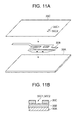
- Fig. 11A is a diagram showing the perspective configuration of the film 30A, the antenna conductor 30B and the insulating layer 30C
- Fig. 11B is a diagram showing the cross-sectional configuration of the film 30A, the antenna conductor 30B and the insulating layer 30C.
- the antenna conductor 30B is first formed on the film 30A.
- the formation of the antenna conductor 30B is implemented by a method such as etching on the film 30A, adhesion of adhesive agent, double-sided adhesive tape or the like.
- the insulating layer 30C is formed on the film 30A on which the antenna conductor 30B has been formed.
- the formation of the insulating layer 30C is implemented by adhesion of film of FPC or the like.
- the coating material for insulation comprises a resist material such as insulating ultraviolet effect resin or the like.
- the insulating layer 30C is formed so that the hole portions 30C1 and 30C2 are set at the soldering position of the feed point P.
- the coaxial cable 40 is soldered to the hole portions 30C1 and 30C2 of the insulating layer 30C shown in Figs. 11A and 11B .
- a soldering manufacturer may solder the hole portions 30C1 and 30C2 which are formed in advance, and an unskilled person can easily solder and prevent the soldering position from being displaced. Furthermore, the unnecessary film 30A and insulating layer 30C are deleted.
- the antenna element 311 is connected to the ground portion 320 through the short stubs 312 and 313, and the feeding point P is provided between the antenna element 311 and the ground portion 320.
- the antenna element 311 has a triangular shape with such an angle that a distance between the antenna element 311 and the ground portion 320 increases with increasing distance from the feeding point P along the ground portion 320.
- the antenna element 311 has such a length that the antenna element 311 resonates at the high frequency f1.
- the antenna element 314 has such a length that the antenna element 314 resonates at the low resonance frequency f2. With this structure, the antenna element 311 has a plurality of antenna current routes different in length.
- the band width of each of the resonance frequency f1 band and the resonance frequency f2 band can be extended. Moreover, because the planar antenna 30 (the antenna portion 310 and the ground portion 320) is planar, the storage space can be reduced. Furthermore, the handy terminal 1 having the planar antenna 30 can perform the wireless communication in which the respective band widths of the resonance frequency f1 band and the resonance frequency f2 bands are wide.
- the antenna element 314 is connected to the antenna element 311 through the two short stubs 315, 316. Therefore, there exist a plurality of routes in which current flows through at least one of the short stubs 315 and 316 at a frequency in the neighborhood of the frequency f2, and thus the band width of the resonance frequency f2 band can be extended.
- the length of the side S1 is set to 1/4 of the wavelength ⁇ 1 of the radio wave of the resonance frequency f1
- the length of the side S2 is set to 1/4 of the wavelength ⁇ 2 of the radio wave of the resonance frequency f2. Therefore, the polarization direction of the radio wave emitted from the planar antenna 30 can be varied, and the gain can be increased.
- the side S2 which is vertical when the handy terminal 1 is used is set to correspond to the lower resonance frequency f2, so that the polarization direction of the radio wave of the resonance frequency f2 having a small gain can be set to the same vertically polarized wave direction as the base station, and thus the gain can be increased.
- the ground portion 330 comprises the ground portion 320 formed on the film 30A and the chassis portion 5. Accordingly, the chassis portion 5 can be used as the ground, and the planar antenna 30 (the antenna portion 310, the ground portion 320) and the storage space thereof can be more greatly reduced. Furthermore, the material of the ground portion 320 is reduced, and thus the cost can be reduced.
- the planar antenna 30 has the insulating layer 30C. Therefore, even when the packaging density of the planar antenna 30 in the handy terminal 1 is increased, the antenna conductor portion 30B can be prevented from being short-circuited to the other parts, the cable, etc.
- the insulating layer 30C has the soldering hole portions 30C1 and 30C2 for the coaxial cable 40 at the feeding point P. Therefore, the soldering position can be fixedly provided at the manufacturing stage, and variation of the antenna performance due to production tolerance can be eliminated.
- a first modification of the above embodiment will be described with reference to Figs. 12A and 12B .
- the device configuration of this modification resides in that the planar antenna 30 in the handy terminal 1 is replaced by planar antennas 60a and 60b.
- the configuration of the planar antennas 60a and 60b will be mainly described, and the description of the other configuration is omitted.
- Fig. 12A is a diagram showing the configuration of the planar antenna 60a.
- the planar antenna 60a comprises an antenna portion 610a and a ground portion 630 as an antenna conductor portion.
- the antenna portion 610a has an antenna element 611 as a first antenna element, a short stub 612 as a first short stub, an antenna element 614 as a second antenna element and short stubs 615 and 616 as second short stubs.
- the ground portion 630 contains the ground portion of the antenna conductor portion and the chassis portion 5.
- the antenna element 611, the antenna element 614, the short subs 615 and 616 and the ground portion 630 are the same as the antenna element 311, the antenna element 314, the short stubs 315, 316 and the ground portion 330 of the planar antenna 30 in this order.
- planar antenna 60a a feeding point P is provided between the antenna element 611 and the ground portion 630. Furthermore, the planar antenna 60a has a film and an insulating layer (not shown) as in the case of the film 30A and the insulating layer 30C of the planar antenna 30.
- the planar antenna 60a is provided with a single short stub 612 instead of the two short stubs 312 and 313, and one end of the antenna element 611 is short-circuited to the ground portion 630 through the short stub 612.
- the short stub 612 has such a shape and width that the empty area between the short stubs 312 and 313 is filled.
- planar antenna 60a of this modification the same advantage as the planar antenna 30 can be obtained. This is because the current flowing in the short stub 612 concentrates on both the right and left end portions thereof and thus the short stub 612 has the same function as the short stubs 312 and 313. Furthermore, three or more short stubs may be provided to connect the antenna element 611 and the ground portion 630.
- Fig. 12B is a diagram showing the configuration of a planar antenna 60b.
- the planar antenna 60b comprises an antenna portion 610b and a ground portion 630 as an antenna conductor.
- the antenna portion 610b has an antenna element 611, a short stub 612, an antenna element 614 and a short stub 617 as a second short stub.
- the planar antenna 60b has a film and an insulating layer (not shown) as in the case of the film 30A and the insulating layer 30C of the planar antenna 30.
- the planar antenna 60b is provided with a single short stub 617 instead of the two short stubs 615 and 616, and one end of the antenna element 614 is short-circuited to the antenna element 611 through the short stub 617.
- the short stub 617 has such a shape and width that the empty area between the short stubs 615 and 616 is filled.
- planar antenna 60b of this modification the same advantage as the planar antenna 30 is obtained. This is because current flowing in the short stub 617 concentrates on both the right and left end portions and thus the short stub 617 has the same function as the short stubs 615 and 616. Three or more short stubs may be provided to connect the antenna element 611 and the antenna element 614.
- a second modification of the above embodiment will be described with reference to Fig. 13 .
- the device configuration of this modification resides in that the planar antenna 30 in the handy terminal 1 is replaced by a planar antenna 70.
- the configuration of the planar antenna 70 will be mainly described, and the description of the other configuration is omitted.
- Fig. 13 is a diagram showing the configuration of the planar antenna 70.
- the planar antenna 70 has an antenna portion 710 and a ground portion 730 as an antenna conductor portion.
- the antenna portion 710 has an antenna element 711 as a first antenna element, a short stub 712 as a first short stub, an antenna element 714 as a second antenna element, and short stubs 715 and 716 as second short stubs.
- the ground portion 730 contains the ground portion of the antenna conductor portion and the chassis portion 5.
- the antenna element 714, the short stubs 715 and 716 and the ground portion 730 are the same as the antenna element 314, the short stubs 315 and 316 and the ground portion 330 of the planar antenna 30 in this order.
- the planar antenna 70 has a film and an insulating layer (not shown) as in the case of the film 30A and the insulating layer 30C of the planar antenna 30.
- the antenna element 711 has a right triangular shape, and a feeding point P is provided between a vertex portion at the lower side of Fig. 13 and the ground portion 730. That is, the antenna element 711 has a shape with such an angle that a distance between the antenna element 711 and the ground portion 730 increases with increasing distance from the feeding point P along the upper side of the ground portion 730.
- the short stub 712 is located below the short stub 715.
- the antenna element 711 is short-circuited to the ground portion 730 through the short stub 712.
- the antenna element 711, the ground portion 730 and the short stub 712 constitutes a loop.
- the same advantage as the planar antenna 30 can be obtained. Furthermore, the position of the feeding point P provided between the antenna element and the ground portion may be changed to another position in the loop constructed by the short stub.
- the antenna element corresponding to the resonance frequency f1 may have a shape with such an angle that a distance between the antenna element and the ground portion increases with increasing distance from the feeding point P along the upper side of the ground portion.
- a third modification of the above embodiment will be described.
- the device configuration of this modification resides in that the planar antenna 30 in the handy terminal 1 is replaced by a planar antenna 80.
- the configuration of the planar antenna 80 will be mainly described, and the description of the other configuration is omitted.
- Fig. 14 is a diagram showing the configuration of the planar antenna 80.
- the planar antenna 80 comprises, as an antenna conductor portion, an antenna portion 810 and a ground portion 820 as a first conductor.
- the antenna portion 810 has an antenna element 811 as a first antenna element, short stubs 812 and 813 as first short tubs, an antenna element 814 as a second antenna element and short stubs 815 and 816 as second short stubs.
- the antenna element 811, the short stubs 812 and 813, the antenna element 814, the short stubs 815 and 816 and the ground portion are the same as the antenna element 311, the short stubs 312 and 313, the antenna element 314 and the short stubs 315 and 316 in this order.
- the ground portion 320 which is the conductor sandwiched between the film 30A and the insulating layer 30C is provided integrally with the chassis portion 5 and considered as the ground portion 330.
- the planar antenna 80 has a ground portion 820 which is a conductor sandwiched between the film and the insulating layer.
- a feeding point P is provided between the antenna element 811 and the ground portion 820.
- the ground portion 820 is not directly electrically connected to the chassis portion 5.
- the ground portion 820 is rectangular, and the length in the short-side direction thereof is represented by L1 while the length in the longitudinal direction thereof is represented by L2.
- the length L1 is set to the length of 1/4 of the wavelength ⁇ 1 of the higher resonance frequency f1
- the length L2 is set to the length of 1/4 of the wavelength ⁇ 2 of the lower resonance frequency.
- planar antenna 80 of this modification the same advantage as the planar antenna 30 can be obtained, and also the ground portion 820 of the planar antenna 80 can be manufactured integrally with the film, the conductor and the insulator.
- the handy terminal is used as the electronic device.
- the present invention may be applied to PDA (Personal Digital Assistant), a cellular phone, a portable communication terminal, a portable device having a wireless communication function such as a portable type computer or the like, and other electronic devices.
- the antenna element 311 may be oblong or the like, and a plurality of short stubs may be provided to connect the antenna element 311 and the antenna element 314.
- the ground portion may be constructed by only a ground part which is not the antenna conductor portion such as the chassis portion 5 or the like. Furthermore, at least two of the above embodiment and the modifications may be properly combined with each other.
- the ground portion is rectangular, and the length L1 in the horizontal direction corresponds to the higher resonance frequency f1 while the length L2 in the vertical direction corresponds to the lower resonance frequency f2.
- the present invention is not limited to this style.
- the length L1 in the horizontal direction may correspond to the resonance frequency f2 while the length L2 in the vertical direction corresponds to the resonance frequency f1.
- the planar antenna is the multiband antenna resonating at the two frequency bands, however, the present invention is not limited to this style.
- the number of the antenna elements of the planar antenna may be set to three or more so that a multiband antenna resonating at three or more frequency bands corresponding to the lengths of the respective antenna elements is constructed.
- planar antenna having the three resonance frequency bands will be described.
- Fig. 15 is a diagram showing the configuration of the planar antenna 90 having the three resonance frequency bands.
- the planar antenna 90 has an antenna portion 910 and a ground portion 930 as an antenna conductor portion.
- the antenna portion 910 has an antenna element 911 as a first antenna element, short stubs 912 and 913 as first short stubs, an antenna element 914 as a second antenna element, short stubs 915 and 916 as second short stubs, an antenna element 917 and a short stub 918.
- the ground portion 930 contains the ground portion of the antenna conductor portion and the chassis portion 5.
- the antenna element 911, the short stubs 912 and 913, the antenna element 914, the short stubs 915 and 916 and the ground portion 930 are the same as the antenna element 311, the short stubs 312 and 313, the antenna element 314, the short stubs 315 and 316 and the ground portion 330 of the planar antenna 30 in this order.
- the antenna element 917 is connected to the antenna element 914 through the short stub 918.
- An end portion of the antenna element 914 (the connection side to the short stub 915) and an end portion of the antenna element 917 are connected to each other through the short stub 918.
- the antenna element 911 has a length at which it resonates at a frequency f1.
- the antenna element 914 has a length at which it resonates at a frequency f2 lower than the frequency f1.
- the antenna element 917 has a length at which it resonates at a frequency f3 between the frequency f1 and the frequency f2.
- the resonance frequency is not limited to the relationship of f2 ⁇ f3 ⁇ f1, and it may satisfy the relationship of f3 ⁇ f2 ⁇ f1, for example.
- the shape of the ground portion may be a shape having three or more sides different in length from one another, such as a trapezoid, and each side may have the length corresponding to each resonance frequency (the length of 1/4 of the wavelength of the radio wave of the resonance frequency).
- the insulating layer of the planar antenna is located at the case 2 side.
- the present invention is not limited to this style.
- the film of the planar antenna may be located at the case 2 side.
- the hole portion penetrating through the film and the insulating layer may be provided at a portion in which no antenna conductor portion exists.
- another insulating part for example, an insulating support part for the case 2 or the like may be made to penetrate through the hole portion.
Abstract
Description
- The present invention relates to a planar antenna and an electronic device.
- Portable devices such as a handy terminal having a wireless communication function, PDA (Personal Digital Assistant), etc. have been known. A planar multiband antenna has been proposed as an antenna for wireless communication which is provided in a portable device (see
JP-A-2007-13596 - An inversed F-shaped antenna having an inversed F-shaped antenna element has also been known as an antenna for wireless communication. Furthermore, a multiband inversed F-shaped antenna has also been proposed (see
JP-A-10-93332 - However, the conventional multiband inversed F-shaped antenna has a plurality of rectangular antenna elements, and the band width of each resonance frequency is structurally narrow.
- Since the conventional multiband inversed F-shaped antenna has a cubic resonance structure, a storage space for the antenna has to be large.
- It is, therefore, a main object of the present invention to extend the band width of a resonance frequency band in a multiband antenna and also reduce a storage space for the antenna.
- According to a first aspect of the present invention, there is provided a planar antenna, including: a film formed of a planar insulating material; an antenna portion which is a planar conductor on the film; and a ground portion which is a conductor to be grounded, wherein the antenna portion includes: at least one first short stub; a first antenna element which is connected to the ground portion through the at least one first short stub and whose shape has such an angle that a distance between the first antenna element and the ground portion increases with increasing distance from a feeding point along the ground portion, the feeding point being provided between the first antenna element and the ground portion; a second short stub; and a second antenna element which is connected to the first antenna element through the second short stub.
- According to a second aspect of the present invention, there is provided a planar antenna, including: a film formed of a planar insulating material; an antenna portion which is a planar conductor on the film; and a ground portion which is a conductor to be grounded, wherein the antenna portion includes: at least one first short stub; a first antenna element which is connected to the ground portion through the at least one first short stub, a feeding point being provided between the first antenna element and the ground portion; a plurality of second short stubs; and a second antenna element which is connected to the first antenna element through the second short stubs.
- According to the present invention, the band width of each of the plurality of resonance frequency bands can be extended in the multiband antenna, and a storage space for the antenna can be reduced.
- Furthermore, according to the present invention, the band width of the resonance frequency band corresponding to a second antenna element can be extended in the multiband antenna, and also a storage space for the antenna can be reduced.
- The above and other objects, advantages and features of the present invention will become more fully understood from the detailed description given hereinbelow and the appended drawings which are given by way of illustration only, and thus are not intended as a definition of the limits of the present invention, and wherein:
-
Fig. 1 is a front view showing a handy terminal according to preferred embodiments of the present invention; -
Fig. 2A is a perspective view of a back side of the handy terminal; -
Fig. 2B is a perspective view of one side of the handy terminal; -
Fig. 2C is a perspective view of a top side of the handy terminal; -
Fig 3 is a block diagram showing a circuit configuration of the handy terminal; -
Fig. 4 shows a configuration of a planar antenna according to the embodiments; -
Fig. 5 shows a connection configuration between the planar antenna and a coaxial cable in the embodiments; -
Fig. 6 shows a configuration of a basic multiband planar antenna; -
Fig. 7 shows routes of current flowing through the planar antenna of the embodiments; -
Fig. 8 shows a relationship between a frequency and an S parameter in the planar antenna of the embodiments, and routes of current under resonance around a second frequency; -
Fig. 9 shows an antenna element and a ground element around a feeding point P; -
Fig. 10A shows current distribution per unit length when a radio wave having a first resonance frequency is radiated in the planar antenna of the embodiments; -
Fig. 10B shows current distribution per unit length when a radio wave having a second resonance frequency is radiated in the planar antenna; -
Fig. 11A is a perspective view showing a film, an antenna conductor portion and an insulating layer; -
Fig. 11B is a cross-sectional view of the film, the antenna portion and the insulating layer; -
Fig. 12A shows a configuration of a planar antenna according to a first modification; -
Fig. 12B shows a configuration of another planar antenna according to the first modification; -
Fig. 13 shows a configuration of a planar antenna according to a second modification; -
Fig. 14 shows a configuration of a planar antenna according to a third modification; and -
Fig. 15 shows a configuration of a planar antenna having three resonance frequencies. - Reference will now be made in detail to preferred embodiments of the present invention and first to third modifications as illustrated in the accompanying drawings. The present invention is not to be considered limited to what is shown in the drawings and the following detailed description.
- The embodiments of the present invention will be described with reference to
Figs. 1 to 10 . First, a device configuration of the embodiments will be explained with reference toFigs. 1 to 5 . -
Fig. 1 is a front view showing a front-side configuration of ahandy terminal 1 according to an embodiment.Fig. 2A is a perspective view showing a perspective configuration of the back side of thehandy terminal 1,Fig. 2B is a perspective view showing a perspective configuration of one side of thehandy terminal 1, andFig. 2C is a perspective view showing a perspective configuration of the top side of thehandy terminal 1. - The
handy terminal 1 as an electronic device according to the embodiment is a portable terminal having functions such as input of information through a user's operation, storage of information, bar-code scanning, etc. Thehandy terminal 1 has ha as a function of performing wireless communication with an external device through an access point according to the wireless LAN (Local Area Network) system, and a cellular phone communication function based on the GSM (Global System for Mobile Communications) system. - The electronic device of this embodiment is not limited to the
handy terminal 1, and it may contain electronic devices such as PDA (Personal Digital Assistance), a cellular phone, a portable communication terminal, a portable device having a wireless communication function such as a portable computer, etc. - As shown in
Fig. 1 , thehandy terminal 1 has adisplay unit 14, atrigger key 3A, various kinds ofkeys 3C, etc. on the front surface of acase 2. Thehandy terminal 1 hastrigger keys 3B on both the side surfaces of thecase 2. Thetrigger keys keys 3C are character input keys of numerals, etc., and function keys for accepting the input of various kinds of functions such as mode switching, etc. - As shown in
Figs. 2A, 2B and 2C , thehandy terminal 1 has aplanar antenna 30, acoaxial cable 40 as a feeding cable, amain board 4, achassis portion 5 as a second conductor portion, aGSM module 5a, abattery 6, akey board 3a, ascanning unit 19, etc. - The respective parts of the
handy terminal 1 are connected to themain board 4. Theplanar antenna 30 is an antenna used for the cellular phone communication as described above. Furthermore, theplanar antenna 30 is fixed to thechassis portion 5 through screws. Theplanar antenna 30 will be described in detail later. - The
chassis portion 5 is a chassis portion of theGSM module 5a, etc. Thechassis portion 5 is formed of metal (conductor) of magnesium alloy, aluminum or the like, and electrically grounded. Therefore, the chassis portion functions as a ground portion of theplanar antenna 30.
Thechassis portion 5 is regarded as being substantially rectangular, and the length in the short-side direction (lateral direction) and the length in the long-side direction (longitudinal direction) are represented by L1 and L2, respectively. The lengths L1 and L2 correspond to the resonance frequencies of radio waves transmitted and received by theplanar antenna 30. TheGSM module 5a is a module for performing the cellular-phone communication and is connected to theplanar antenna 30 through acoaxial cable 40. - The
scanning unit 19 is a reading module for applying light such as a laser beam or the like to a bar-code and receiving and binarizing reflection light from the bar-code to read data of the bar-code. Thebattery 6 supplies power for the power supply of thehandy terminal 1. Thekey board 3a is provided with thetrigger key 3A and the various kinds ofkeys 3C thereon, and outputs key input signals of these keys to themain board 4. -
Fig. 3 is a block diagram showing the circuit configuration of thehandy terminal 1. - As shown in
Fig. 3 , thehandy terminal 1 has CPU (Central Processing Unit) 11 as a controller, aninput unit 12, RAM (Random Access Memory) 13, adisplay unit 14, ROM (Read Only Memory) 15, awireless communication unit 16 as a communication unit having aplanar antenna 30, aflash memory 17, a wirelessLAN communication unit 18 having anantenna 18a, ascanning unit 19, I/F (Inter Face) 20, etc., and the respective parts are connected to one another through abus 21. - The
CPU 11 controls the respective units of thehandy terminal 1. TheCPU 11 reads out a specified program from theROM 15 which stores a system program and various application programs, loads the specified program into theRAM 13, and carries out various processing in cooperation with the program loaded into theRAM 13. - In cooperation with the various programs, the
CPU 11 accepts an input of operating information through theinput unit 12, reads out various information from theROM 15, reads out and writes various information from and into theflash memory 17. Moreover, theCPU 11 controls thewireless communication unit 16 so that thehandy terminal 1 can communicate with an external device through a base station using theplanar antenna 30. TheCPU 11 controls the wirelessLAN communication unit 18 so that thehandy terminal 1 can communicate with an external device through an access point using theantenna 18a. TheCPU 11 controls thescanning unit 19 to read data of a bar code. TheCPU 11 communicates with an external device through the I/F 20 using a communication cable. - The
input unit 12 includes thetrigger keys various keys 3C, and outputs a key input signal of each key pressed by an operator to theCPU 11. Theinput unit 12 may be designed to integrate with thedisplay unit 14 so that a touch panel can be formed. - The
RAM 13 is a volatile memory for temporarily storing information. TheRAM 13 has a working area for temporarily storing various programs executed by theCPU 11 and various data associated with these programs. - The
display unit 14 has a display such as liquid crystal display (LCD) and electro luminescent display (ELD). Thedisplay unit 14 executes a display processing in accordance with a signal from theCPU 11. - The
ROM 15 is a read only storage unit in which various programs and data are stored. - The
wireless communication unit 16 is connected to theplanar antenna 30, and transmits/receives information to/from a base station through the GMS type communication by using theplanar antenna 30. In this embodiment, multiband wireless communication whose resonance frequency bands are set to about 800[MHz] band (frequency f2 band) and about 1900[MHz] band (frequency f1 band) is performed as the GSM type communication. Theplanar antenna 30 is also matched with these resonance frequency bands. However, the present invention is not limited to this embodiment, and theplanar antenna 30 and thewireless communication unit 16 may be adapted to other resonance frequency bands or designed to perform wireless communications based on other wireless communication systems. - The
flash memory 17 is a storage unit which can read out and write information such as various kinds of data. - The wireless
LAN communication unit 18 is connected to theantenna 18a. The wirelessLAN communication unit 18 sends and receives information to and from an external device using theantenna 18a through an access point via wireless LAN communication. - The
scanning unit 19 has a light emitting unit for laser beam or the like, a light receiving unit, a gain circuit, a binarizing circuit, etc. In thescanning unit 19, light emitted from the light emitting unit is applied to a bar-code, and reflection light from the bar-code is received and converted to an electrical signal by the light receiving unit. The electrical signal is amplified in the gain circuit, and converted to data of a white and black bar-code image in the binarizing circuit. As described above, thescanning unit 19 reads a bar-code image, and outputs the data of the bar-code image concerned toCPU 11. - The I/
F 20 sends and receives information to and from an external device through a communication cable. The I/F 20 is a cable communication unit using universal serial bus (USB), for example. - Next, a configuration of the
planar antenna 30 will be explained with reference toFig. 4 . -
Fig. 4 shows a configuration of theplanar antenna 30. - The
planar antenna 30 includes afilm 30A, anantenna conductor portion 30B and an insulatinglayer 30C. Thefilm 30A is a film of FPC (Flexible Print Circuit), and is formed of an insulator such as polyimide. Theantenna conductor 30B is formed of a single planar conductor such as copper foil, and is print-wired on thefilm 30A. The insulatinglayer 30C is formed of an insulator as a film of FPC, for example, and is formed on thefilm 30A and theantenna conductor 30B. The insulatinglayer 30C has hole portions 30C1 and 30C2 for soldering. - The
antenna conductor 30B comprises anantenna portion 310 and aground portion 320 as a first conductor portion. Power is supplied to theantenna portion 310 and theground portion 320 is grounded. Theantenna portion 310 has anantenna element 311 as a first antenna element,short stubs antenna element 314 as a second antenna element, andshort stubs ground portion 320 has aground element 321 and screw holes 322. - The
antenna element 311 is an antenna element for resonance at a higher resonance frequency f1 of the two resonance frequencies f1 and f2. Theantenna element 311 has an almost triangular shape so that a vertex of the triangle is located in the neighborhood of theground element 321. - The
coaxial cable 40 is connected between the vertex portion of the antenna element 311 (corresponding to the position of the hole portion 30C1) and an opposed portion to the vertex portion of the ground element 321 (corresponding to the position of the hole portion 30C2) by soldering. This connection portion is referred to as a feeding point P. - The
antenna element 311 is connected to theshort stub 312 at one end in the longitudinal direction thereof, and also connected to theshort stub 313 so as to be spaced from the connection position of theshort stab 312 at a predetermined distance. Furthermore, theshort stub 312 is connected to theground element 321. Theshort stub 313 is connected to theground element 321 so as to be spaced from the connection position between theshort stub 312 and theground element 321 at a predetermined distance. - The
antenna element 314 is an antenna element for resonance at a lower resonance frequency f2 of the two resonance frequencies f1 and f2. Theantenna element 314 is strip-shaped, and has a bending portion at some midpoint thereof. The bending portion is matched with the mount space of theplanar antenna 30, and the present invention is not limited to this shape. Theantenna element 314 is connected to theshort stub 315 at one end in the longitudinal direction thereof, and also connected to theshort stub 316 so as to be spaced from the connection point of theshort stub 315 at a predetermined distance. Furthermore, theshort stub 315 is connected to a predetermined position of an intermediate portion in the longitudinal direction of theantenna element 311. The longitudinal directions of theantenna element 311, theantenna element 314 and theground element 321 are set to one another. - The
ground element 321 is trapezoidal, however, the present invention is not limited to this shape. Theground element 321 is fixedly connected and electrically conducted to thechassis portion 5 by fixing screws through the screw holes 322. Therefore, theground portion 320 and thechassis portion 5 integrally function as the ground. - Next, the connection between the
planar antenna 30 and thecoaxial cable 40 at the feeding point P will be described with reference toFig. 5 . -
Fig. 5 is a diagram showing the connection configuration between theplanar antenna 30 and thecoaxial cable 40. Thefilm 30A and the insulatinglayer 30C are omitted from the illustration ofFig. 5 . - The
coaxial cable 40 has acore wire 41 formed of copper wire or the like, aninsulator 42 formed of polyethylene or the like, anexternal conductor 43 formed of a meshed copper wire or the like and aprotection coating member 44 as an insulator which are successively arranged concentrically. Thecore wire 41 at one end of thecoaxial cable 40 is passes through the hole portion 30C1 and connected to theantenna element 311 by soldering, and theexternal conductor 43 is passes through the hole portion 30C2 and connected to theground element 321 by soldering.
The other end of thecoaxial cable 40 is connected to theGSM module 5a. Thecore wire 41 at the other end of thecoaxial cable 40 is connected to a power feeding terminal of theGSM module 5a, and theexternal conductor 43 is connected to the ground of theGSM module 5a. High frequency power is supplied from theGSM module 5a through thecoaxial cable 40 to the feeding point P. - Next, the details of the
planar antenna 30 will be described with reference toFigs. 6 to 10 . In order to simplify the description and the illustration, theantenna conductor portion 30B of theplanar antenna 30 will be described, and the description and illustration of thefilm 30A and the insulatinglayer 30C are omitted. - First, the operation principle of a basic multiband
planar antenna 50 will be described. -
Fig. 6 is a diagram showing the configuration of the basic multibandplanar antenna 50. Theplanar antenna 50 is an antenna resonating at frequencies f1 and f2. - As shown in
Fig. 6 , theplanar antenna 50 has anantenna portion 510 and aground portion 520. Theantenna portion 510 has aantenna element 511,short stubs antenna element 514 and ashort stub 515 which are rectangular in shape. - The
antenna element 511 is disposed so that the longitudinal direction thereof is parallel to theground portion 520, and connected to theground portion 520 through theshort stubs antenna element 514 is disposed so that the longitudinal direction thereof is parallel to the longitudinal direction of theantenna element 511, and connected to theantenna element 511 through theshort stub 515. A feeding point P is provided between one end of theshort stub 513 and theground portion 520. - The
ground portion 520, theshort stub 513, theantenna element 511 and theshort stub 512 constitutes a minute loop portion, and loop current flows into the loop portion, whereby the impedance matching is established and the depth of the resonance is adjusted. - The length L3 of a route passing through the
short stub 512 and theantenna element 511 as a current-flowing route is set to 1/4 of the wavelength λ1 of the resonance frequency f1. Likewise, the length L4 of a route passing through theshort stub 512, theantenna element 511, theshort stub 515 and theantenna element 514 as a current-flowing route is set to 1/4 of the wavelength λ2 of the resonance frequency f2. Therefore, theplanar antenna 50 functions as a multiband antenna resonating when the radio waves of the two resonance frequency f1, f2 bands are transmitted/received, thereby obtaining a high gain. - As described above, the
planar antenna 50 is the multiband antenna of the two resonance frequency f1, f2 bands. However, there is a little mode resonating in each frequency band, so that the band width thereof is relatively narrow. - Next, the
planar antenna 30 according to this embodiment will be described. First, as in the case of theplanar antenna 50, theplanar antenna 30 resonates at the two resonance frequencies f1, f2 (f1 > f2). The length of a route passing through theshort stubs antenna element 311 as a current-flowing route is set to 1/4 of the wavelength λ1 of the resonance frequency f1. Furthermore, the length of a route passing through theshort stubs antenna element 311, theshort stubs antenna element 314 as a current-flowing route is set to 1/4 of the wavelength λ2 of the resonance frequency f2. - Next, the configuration of broadening the resonance frequency band of the
planar antenna 30 will be described. -
Fig. 7 is a diagram showing a route for current flowing through theplanar antenna 30. - As shown in
Fig. 7 , theplanar antenna 30 has anantenna portion 310 and aground portion 330. Theground portion 330 is a ground portion when theground portion 320 and thechassis portion 5 are regarded as being integral with each other. - By designing the
antenna element 311 in a substantially triangular shape, a plurality of length-different routes (a plurality of modes) through which current flows can be formed between the feeding point P in the neighborhood of the vertex of the triangle of theantenna element 311 and each end in the longitudinal direction of theantenna element 311 so as to be displaced inside, and thus theantenna element 311 resonates at the different modes, thereby securing the plurality of routes having different lengths through which current flows. The length of the route varies in accordance with the magnitude of the frequency. Therefore, the resonance frequency band is extended by the routes of the plurality of lengths. - Next, another configuration of broadening the resonance frequency band of the
planar antenna 30 will be described. -
Fig. 8 is a diagram showing a relationship between frequency and an S parameter in theplanar antenna 30, and routes of current under resonance around a second frequency f2. The S parameter is called as a scattering matrix (S matrix) or a scattering parameter. The S parameter represents a passage/reflection power characteristic of a circuit network. - As shown in
Fig. 8 , the S parameter with respect to frequency is low around frequencies f1 and f2. A high gain is obtained in the band widths containing the frequencies f1 and f2 as the resonance frequencies. As shown inFig. 8 , the S-parameter low portions around the frequencies f1 and f2 are broad, and thus the band width of the resonance frequency thereof is extended. - As compared with the
planar antenna 50, in theplanar antenna 30, theantenna element 314 resonating at the frequency f2 is short-circuited to theantenna element 311 resonating at the frequency f1 through theshort tub 315 and theshort tub 316. As shown inFig. 8 , in the band of the frequency f2, when the resonating frequency is lower than the frequency f2, current flows through the route passing through theshort stub 312, theantenna element 311, theshort stub 315 and theantenna element 314. - When the resonating frequency is in the neighborhood of the center of the band of the frequency f2, current flows in the route passing through the
short stub 312, theantenna element 311, theshort stub 315 and theantenna element 314 and in the route passing through theshort stub 312, theantenna element 311, theshort stub 316 and theantenna element 314. When the resonance frequency is higher than the frequency f2, the current flows through theshort stub 312, theantenna element 311, theshort stub 316, and theantenna element 314. - Therefore, the place to which current is concentrated varies due to the provision of the
short stub 316, and thus the same advantage obtained when the plurality of antenna elements different in length exist is obtained, and the band width of the resonance frequency band of the lower frequency f2 out of the two resonance frequencies f1 and f2 can be extended. - Next, the impedance matching in the
planar antenna 30 will be described. -
Fig. 9 is a diagram showing theantenna element 311 and theground element 321 in the neighborhood of the feeding point P. - As shown in
Fig. 9 , theantenna element 311 has a substantially triangular shape having angles θ1 and θ2 with respect to theground element 321 with the feeding point P at the center. When the angles θ1 and θ2 increase, the impedance viewed from the feeding point P increases. Furthermore, when the angles θ1 and θ2 decrease, the impedance viewed from the feeding point P is lowered. The matching of the impedance viewed from the feeding point P can be established by adjusting the angles θ1 and θ2. - Next, the shape and size of the ground portion will be described.
-
Fig. 10A is a diagram showing current distribution per unit length in theplanar antenna 30 when a radio wave having the resonance frequency f1 is emitted. -
Fig. 10B is a diagram showing current distribution per unit length in theplanar antenna 30 when a radio wave having the resonance frequency f2 is emitted. - In
Figs. 10A and 10B , it is assumed that the current per unit length increases as the drawing color is shifted from black to white. - As shown in
Fig. 2A andFigs. 10A and 10B , in theplanar antenna 30, the length of the side S1 in the short-side direction (horizontal direction) of theground portion 330 is represented by L1, and the length of the side S2 in the longitudinal direction (vertical direction) is represented by L2. Here, the horizontal direction and the vertical direction are defined with respect to the ground surface when thehandy terminal 1 is used. The length L1 is set to 1/4 of the wavelength λ1 of the higher resonance frequency f1, and the length L2 is set to 1/4 of the wavelength λ2 of the lower resonance frequency f2. - As shown in
Fig. 10A , in theplanar antenna 30, an area in the vicinity of the side S1 resonates and current concentrates there when the radio wave of the resonance frequency f1 is emitted, so that the emitted radio wave is a horizontally-polarized wave. - As shown in
Fig. 10B , in theplanar antenna 30, an area in the vicinity of the side S2 resonates and current concentrates there when the radio wave of the resonance frequency f2 is emitted, so that the emitted radio wave is a vertically-polarized wave. As described above, the polarization direction of the wave transmitted/received to/from theplanar antenna 30 can be varied. - The base station receives the radio wave of the vertically-polarized wave. Electrical waves having low frequencies are little reflected, and thus it is preferable to set the radio wave of the lower frequency f2 to the vertically polarized wave in conformity with the base station. Accordingly, the length of the side S2 in the vertical direction of the
ground portion 330 is set to correspond to the resonance frequency f2. - Next, the process of manufacturing the
planar antenna 30 will be described. -
Fig. 11A is a diagram showing the perspective configuration of thefilm 30A, theantenna conductor 30B and the insulatinglayer 30C, andFig. 11B is a diagram showing the cross-sectional configuration of thefilm 30A, theantenna conductor 30B and the insulatinglayer 30C. - As shown in
Fig. 11A , theantenna conductor 30B is first formed on thefilm 30A. The formation of theantenna conductor 30B is implemented by a method such as etching on thefilm 30A, adhesion of adhesive agent, double-sided adhesive tape or the like. - The insulating
layer 30C is formed on thefilm 30A on which theantenna conductor 30B has been formed. The formation of the insulatinglayer 30C is implemented by adhesion of film of FPC or the like. However, the present invention is not limited to this manner, and a method of painting coating material for insulation or the like may be used. The coating material for insulation comprises a resist material such as insulating ultraviolet effect resin or the like. The insulatinglayer 30C is formed so that the hole portions 30C1 and 30C2 are set at the soldering position of the feed point P. - As shown in
Fig. 5 , thecoaxial cable 40 is soldered to the hole portions 30C1 and 30C2 of the insulatinglayer 30C shown inFigs. 11A and 11B . A soldering manufacturer may solder the hole portions 30C1 and 30C2 which are formed in advance, and an unskilled person can easily solder and prevent the soldering position from being displaced. Furthermore, theunnecessary film 30A and insulatinglayer 30C are deleted. - As described above, according to the embodiments, in the
planar antenna 30, theantenna element 311 is connected to theground portion 320 through theshort stubs antenna element 311 and theground portion 320. Theantenna element 311 has a triangular shape with such an angle that a distance between theantenna element 311 and theground portion 320 increases with increasing distance from the feeding point P along theground portion 320. Theantenna element 311 has such a length that theantenna element 311 resonates at the high frequency f1. Theantenna element 314 has such a length that theantenna element 314 resonates at the low resonance frequency f2. With this structure, theantenna element 311 has a plurality of antenna current routes different in length. Therefore, the band width of each of the resonance frequency f1 band and the resonance frequency f2 band can be extended. Moreover, because the planar antenna 30 (theantenna portion 310 and the ground portion 320) is planar, the storage space can be reduced. Furthermore, thehandy terminal 1 having theplanar antenna 30 can perform the wireless communication in which the respective band widths of the resonance frequency f1 band and the resonance frequency f2 bands are wide. - The
antenna element 314 is connected to theantenna element 311 through the twoshort stubs short stubs - In the
ground portion 330, the length of the side S1 is set to 1/4 of the wavelength λ1 of the radio wave of the resonance frequency f1, and the length of the side S2 is set to 1/4 of the wavelength λ2 of the radio wave of the resonance frequency f2. Therefore, the polarization direction of the radio wave emitted from theplanar antenna 30 can be varied, and the gain can be increased. Particularly, the side S2 which is vertical when thehandy terminal 1 is used is set to correspond to the lower resonance frequency f2, so that the polarization direction of the radio wave of the resonance frequency f2 having a small gain can be set to the same vertically polarized wave direction as the base station, and thus the gain can be increased. - Furthermore, the
ground portion 330 comprises theground portion 320 formed on thefilm 30A and thechassis portion 5. Accordingly, thechassis portion 5 can be used as the ground, and the planar antenna 30 (theantenna portion 310, the ground portion 320) and the storage space thereof can be more greatly reduced. Furthermore, the material of theground portion 320 is reduced, and thus the cost can be reduced. - The
planar antenna 30 has the insulatinglayer 30C.
Therefore, even when the packaging density of theplanar antenna 30 in thehandy terminal 1 is increased, theantenna conductor portion 30B can be prevented from being short-circuited to the other parts, the cable, etc. - The insulating
layer 30C has the soldering hole portions 30C1 and 30C2 for thecoaxial cable 40 at the feeding point P. Therefore, the soldering position can be fixedly provided at the manufacturing stage, and variation of the antenna performance due to production tolerance can be eliminated. - A first modification of the above embodiment will be described with reference to
Figs. 12A and 12B . The device configuration of this modification resides in that theplanar antenna 30 in thehandy terminal 1 is replaced byplanar antennas planar antennas -
Fig. 12A is a diagram showing the configuration of theplanar antenna 60a. As shown inFig. 12A , theplanar antenna 60a comprises anantenna portion 610a and aground portion 630 as an antenna conductor portion. Theantenna portion 610a has anantenna element 611 as a first antenna element, ashort stub 612 as a first short stub, anantenna element 614 as a second antenna element andshort stubs ground portion 630 contains the ground portion of the antenna conductor portion and thechassis portion 5. Theantenna element 611, theantenna element 614, theshort subs ground portion 630 are the same as theantenna element 311, theantenna element 314, theshort stubs ground portion 330 of theplanar antenna 30 in this order. - In the
planar antenna 60a, a feeding point P is provided between theantenna element 611 and theground portion 630. Furthermore, theplanar antenna 60a has a film and an insulating layer (not shown) as in the case of thefilm 30A and the insulatinglayer 30C of theplanar antenna 30. - The
planar antenna 60a is provided with a singleshort stub 612 instead of the twoshort stubs antenna element 611 is short-circuited to theground portion 630 through theshort stub 612. Theshort stub 612 has such a shape and width that the empty area between theshort stubs - According to the
planar antenna 60a of this modification, the same advantage as theplanar antenna 30 can be obtained. This is because the current flowing in theshort stub 612 concentrates on both the right and left end portions thereof and thus theshort stub 612 has the same function as theshort stubs antenna element 611 and theground portion 630. -
Fig. 12B is a diagram showing the configuration of aplanar antenna 60b. As shown inFig. 12B , theplanar antenna 60b comprises anantenna portion 610b and aground portion 630 as an antenna conductor. Theantenna portion 610b has anantenna element 611, ashort stub 612, anantenna element 614 and ashort stub 617 as a second short stub. Theplanar antenna 60b has a film and an insulating layer (not shown) as in the case of thefilm 30A and the insulatinglayer 30C of theplanar antenna 30. - The
planar antenna 60b is provided with a singleshort stub 617 instead of the twoshort stubs antenna element 614 is short-circuited to theantenna element 611 through theshort stub 617. Theshort stub 617 has such a shape and width that the empty area between theshort stubs - According to the
planar antenna 60b of this modification, the same advantage as theplanar antenna 30 is obtained. This is because current flowing in theshort stub 617 concentrates on both the right and left end portions and thus theshort stub 617 has the same function as theshort stubs antenna element 611 and theantenna element 614. - A second modification of the above embodiment will be described with reference to
Fig. 13 . The device configuration of this modification resides in that theplanar antenna 30 in thehandy terminal 1 is replaced by aplanar antenna 70. The configuration of theplanar antenna 70 will be mainly described, and the description of the other configuration is omitted. -
Fig. 13 is a diagram showing the configuration of theplanar antenna 70. As shown inFig. 13 , theplanar antenna 70 has anantenna portion 710 and aground portion 730 as an antenna conductor portion. Theantenna portion 710 has anantenna element 711 as a first antenna element, ashort stub 712 as a first short stub, anantenna element 714 as a second antenna element, andshort stubs ground portion 730 contains the ground portion of the antenna conductor portion and thechassis portion 5. Theantenna element 714, theshort stubs ground portion 730 are the same as theantenna element 314, theshort stubs ground portion 330 of theplanar antenna 30 in this order. Theplanar antenna 70 has a film and an insulating layer (not shown) as in the case of thefilm 30A and the insulatinglayer 30C of theplanar antenna 30. - The
antenna element 711 has a right triangular shape, and a feeding point P is provided between a vertex portion at the lower side ofFig. 13 and theground portion 730. That is, theantenna element 711 has a shape with such an angle that a distance between theantenna element 711 and theground portion 730 increases with increasing distance from the feeding point P along the upper side of theground portion 730. - The
short stub 712 is located below theshort stub 715. Theantenna element 711 is short-circuited to theground portion 730 through theshort stub 712. Theantenna element 711, theground portion 730 and theshort stub 712 constitutes a loop. - According to the
planar antenna 70 of this modification, the same advantage as theplanar antenna 30 can be obtained. Furthermore, the position of the feeding point P provided between the antenna element and the ground portion may be changed to another position in the loop constructed by the short stub. The antenna element corresponding to the resonance frequency f1 may have a shape with such an angle that a distance between the antenna element and the ground portion increases with increasing distance from the feeding point P along the upper side of the ground portion. - A third modification of the above embodiment will be described. The device configuration of this modification resides in that the
planar antenna 30 in thehandy terminal 1 is replaced by aplanar antenna 80. The configuration of theplanar antenna 80 will be mainly described, and the description of the other configuration is omitted. -
Fig. 14 is a diagram showing the configuration of theplanar antenna 80. As shown inFig. 14 , theplanar antenna 80 comprises, as an antenna conductor portion, anantenna portion 810 and aground portion 820 as a first conductor. Theantenna portion 810 has anantenna element 811 as a first antenna element,short stubs antenna element 814 as a second antenna element andshort stubs antenna element 811, theshort stubs antenna element 814, theshort stubs antenna element 311, theshort stubs antenna element 314 and theshort stubs - In the
planar antenna 30, theground portion 320 which is the conductor sandwiched between thefilm 30A and the insulatinglayer 30C is provided integrally with thechassis portion 5 and considered as theground portion 330. Theplanar antenna 80 has aground portion 820 which is a conductor sandwiched between the film and the insulating layer. In theantenna portion 810, a feeding point P is provided between theantenna element 811 and theground portion 820. Theground portion 820 is not directly electrically connected to thechassis portion 5. - As in the case of the
ground portion 330, theground portion 820 is rectangular, and the length in the short-side direction thereof is represented by L1 while the length in the longitudinal direction thereof is represented by L2. The length L1 is set to the length of 1/4 of the wavelength λ1 of the higher resonance frequency f1, and the length L2 is set to the length of 1/4 of the wavelength λ2 of the lower resonance frequency. - According to the
planar antenna 80 of this modification, the same advantage as theplanar antenna 30 can be obtained, and also theground portion 820 of theplanar antenna 80 can be manufactured integrally with the film, the conductor and the insulator. - The embodiment and the modifications described above are examples of the planar antenna and the electronic device, and the present invention is not limited to these embodiment and modifications.
- In the above embodiment and the above modifications, the handy terminal is used as the electronic device. However, the present invention may be applied to PDA (Personal Digital Assistant), a cellular phone, a portable communication terminal, a portable device having a wireless communication function such as a portable type computer or the like, and other electronic devices.
- In the above embodiment, the
antenna element 311 may be oblong or the like, and a plurality of short stubs may be provided to connect theantenna element 311 and theantenna element 314. The ground portion may be constructed by only a ground part which is not the antenna conductor portion such as thechassis portion 5 or the like. Furthermore, at least two of the above embodiment and the modifications may be properly combined with each other. - Furthermore, in the above embodiment and the modifications, the ground portion is rectangular, and the length L1 in the horizontal direction corresponds to the higher resonance frequency f1 while the length L2 in the vertical direction corresponds to the lower resonance frequency f2. However, the present invention is not limited to this style. For example, the length L1 in the horizontal direction may correspond to the resonance frequency f2 while the length L2 in the vertical direction corresponds to the resonance frequency f1.
- In the above embodiment and the modifications, the planar antenna is the multiband antenna resonating at the two frequency bands, however, the present invention is not limited to this style. For example, the number of the antenna elements of the planar antenna may be set to three or more so that a multiband antenna resonating at three or more frequency bands corresponding to the lengths of the respective antenna elements is constructed.
- Here, an example of the planar antenna having the three resonance frequency bands will be described.
-
Fig. 15 is a diagram showing the configuration of theplanar antenna 90 having the three resonance frequency bands. - As shown in
Fig. 15 , theplanar antenna 90 has anantenna portion 910 and aground portion 930 as an antenna conductor portion. Theantenna portion 910 has anantenna element 911 as a first antenna element,short stubs antenna element 914 as a second antenna element,short stubs antenna element 917 and ashort stub 918. Theground portion 930 contains the ground portion of the antenna conductor portion and thechassis portion 5. Theantenna element 911, theshort stubs antenna element 914, theshort stubs ground portion 930 are the same as theantenna element 311, theshort stubs antenna element 314, theshort stubs ground portion 330 of theplanar antenna 30 in this order. - The
antenna element 917 is connected to theantenna element 914 through theshort stub 918. An end portion of the antenna element 914 (the connection side to the short stub 915) and an end portion of theantenna element 917 are connected to each other through theshort stub 918. Theantenna element 911 has a length at which it resonates at a frequency f1. Theantenna element 914 has a length at which it resonates at a frequency f2 lower than the frequency f1. Theantenna element 917 has a length at which it resonates at a frequency f3 between the frequency f1 and the frequency f2. However, the resonance frequency is not limited to the relationship of f2 < f3 < f1, and it may satisfy the relationship of f3 < f2 < f1, for example. - If the number of the resonance frequencies is equal to three or more, the shape of the ground portion may be a shape having three or more sides different in length from one another, such as a trapezoid, and each side may have the length corresponding to each resonance frequency (the length of 1/4 of the wavelength of the radio wave of the resonance frequency).
- In the above embodiments and the above modifications, the insulating layer of the planar antenna is located at the
case 2 side. However, the present invention is not limited to this style. The film of the planar antenna may be located at thecase 2 side. - In the planar antennas of the above embodiment and the above modifications, the hole portion penetrating through the film and the insulating layer may be provided at a portion in which no antenna conductor portion exists. For example, another insulating part, for example, an insulating support part for the
case 2 or the like may be made to penetrate through the hole portion. - With respect to the detailed configurations and operations of the respective elements of the planar antennas and the handy terminals as electronic devices in the above-described embodiments, it will be apparent to those skilled in the art that various modification and variations can be made without departing from the scope of the invention.
- Although various exemplary embodiments have been shown and described, the invention is not limited to the embodiments shown. Therefore, the scope of the invention is intended to be limited solely by the scope of the claims that follow.
Claims (13)
- A planar antenna, comprising:a film formed of a planar insulating material;an antenna portion which is a planar conductor on the film; anda ground portion which is a conductor to be grounded, wherein the antenna portion comprises:at least one first short stub;a first antenna element which is connected to the ground portion through the at least one first short stub and whose shape has such an angle that a distance between the first antenna element and the ground portion increases with increasing distance from a feeding point along the ground portion, the feeding point being provided between the first antenna element and the ground portion;a second short stub; anda second antenna element which is connected to the first antenna element through the second short stub.
- The planar antenna according to claim 1, comprising a plurality of second short stubs, one of which is the second short stub.
- The planar antenna according to claim 1, wherein the ground portion has a plurality of sides whose respective lengths are 1/4 of wavelengths of resonance frequencies different from one another.
- The planar antenna according to claim 1, wherein the ground portion is at least one of a first conductor portion and a second conductor portion, the first conductor portion being planar and formed on the film, and the second conductor portion not being formed on the film.
- The planar antenna according to claim 1, further comprising an insulating layer formed on the antenna portion and the ground portion.
- The planar antenna according to claim 5, wherein the insulating layer includes a hole portion at a position of soldering a feeding cable at the feeding point.
- A planar antenna, comprising:a film formed of a planar insulating material;an antenna portion which is a planar conductor on the film; anda ground portion which is a conductor to be grounded, wherein the antenna portion comprises:at least one first short stub;a first antenna element which is connected to the ground portion through the at least one first short stub, a feeding point being provided between the first antenna element and the ground portion;a plurality of second short stubs; anda second antenna element which is connected to the first antenna element through the second short stubs.
- The planar antenna according to claim 7, wherein the ground portion has a plurality of sides whose respective lengths are 1/4 of wavelengths of resonance frequencies different from one another.
- The planar antenna according to claim 7, wherein the ground portion is at least one of a first conductor portion and a second conductor portion, the first conductor portion being planar and formed on the film, and the second conductor portion not being formed on the film.
- The planar antenna according to claim 7, further comprising an insulating layer formed on the antenna portion and the ground portion.
- The planar antenna according to claim 10, wherein the insulating layer includes a hole portion at a position of soldering a feeding cable at the feeding point.
- An electronic device, comprising:the planar antenna according to claim 1;a communication unit to communicate with an external device through the planar antenna; anda control unit to control the communication unit.
- An electronic device, comprising:the planar antenna according to claim 7;a communication unit to communicate with an external device through the planar antenna; anda control unit to control the communication unit.
Applications Claiming Priority (1)
| Application Number | Priority Date | Filing Date | Title |
|---|---|---|---|
| JP2008140595A JP4775406B2 (en) | 2008-05-29 | 2008-05-29 | Planar antenna and electronic equipment |
Publications (2)
| Publication Number | Publication Date |
|---|---|
| EP2128925A1 true EP2128925A1 (en) | 2009-12-02 |
| EP2128925B1 EP2128925B1 (en) | 2012-05-16 |
Family
ID=40897382
Family Applications (1)
| Application Number | Title | Priority Date | Filing Date |
|---|---|---|---|
| EP09160450A Active EP2128925B1 (en) | 2008-05-29 | 2009-05-18 | Planar antenna and electronic device |
Country Status (4)
| Country | Link |
|---|---|
| US (1) | US8111200B2 (en) |
| EP (1) | EP2128925B1 (en) |
| JP (1) | JP4775406B2 (en) |
| CN (1) | CN101593871B (en) |
Cited By (2)
| Publication number | Priority date | Publication date | Assignee | Title |
|---|---|---|---|---|
| EP2413426A1 (en) * | 2009-03-24 | 2012-02-01 | Casio Computer Co., Ltd. | Multiband antenna and electronic device |
| WO2018210707A1 (en) * | 2017-05-15 | 2018-11-22 | Thomson Licensing | Antenna structure for wireless systems |
Families Citing this family (23)
| Publication number | Priority date | Publication date | Assignee | Title |
|---|---|---|---|---|
| JP4816564B2 (en) * | 2007-05-17 | 2011-11-16 | カシオ計算機株式会社 | Film antenna and electronic equipment |
| JP4613950B2 (en) | 2007-12-27 | 2011-01-19 | カシオ計算機株式会社 | Planar monopole antenna and electronic equipment |
| JP2010278586A (en) * | 2009-05-27 | 2010-12-09 | Casio Computer Co Ltd | Multi-band planar antenna and electronic device |
| JP5549248B2 (en) * | 2010-02-04 | 2014-07-16 | ソニー株式会社 | Antenna element and communication device |
| JP2011176653A (en) | 2010-02-25 | 2011-09-08 | Fujitsu Component Ltd | Antenna device |
| US8757495B2 (en) * | 2010-09-03 | 2014-06-24 | Hand Held Products, Inc. | Encoded information reading terminal with multi-band antenna |
| JP5364848B2 (en) * | 2010-12-24 | 2013-12-11 | パナソニック株式会社 | Antenna device |
| JP2012160951A (en) * | 2011-02-01 | 2012-08-23 | Toshiba Corp | Multi-resonance antenna device, and electronic apparatus equipped with antenna device |
| US8780007B2 (en) | 2011-05-13 | 2014-07-15 | Htc Corporation | Handheld device and planar antenna thereof |
| JP5662889B2 (en) * | 2011-07-04 | 2015-02-04 | 株式会社日立製作所 | Wireless module |
| US8810465B2 (en) * | 2011-11-16 | 2014-08-19 | Symbol Technologies, Inc. | Distributed comb tapped multiband antenna |
| JP2013187614A (en) * | 2012-03-06 | 2013-09-19 | Yamaha Corp | Antenna |
| DE112013003272B4 (en) * | 2012-06-29 | 2017-08-10 | Fujikura Ltd. | Inverted F-type antenna |
| JP5575208B2 (en) * | 2012-11-21 | 2014-08-20 | 株式会社東芝 | Multi-resonant antenna device and electronic device including the antenna device |
| TWI599107B (en) * | 2013-04-23 | 2017-09-11 | 群邁通訊股份有限公司 | Gps antenna, motherboard and wireless communication device having same |
| KR20160023281A (en) * | 2014-08-22 | 2016-03-03 | 삼성전자주식회사 | Multiband Antenna |
| WO2016045046A1 (en) * | 2014-09-25 | 2016-03-31 | 华为技术有限公司 | Multi-band antenna and communication terminal |
| JP6525249B2 (en) * | 2015-03-20 | 2019-06-05 | カシオ計算機株式会社 | Antenna device and electronic device |
| TWI599094B (en) * | 2016-01-07 | 2017-09-11 | 宏碁股份有限公司 | Portable electronic device |
| TWI619305B (en) * | 2016-02-19 | 2018-03-21 | 群邁通訊股份有限公司 | Antenna structure and wireless communication device with same |
| JP6791810B2 (en) * | 2017-06-09 | 2020-11-25 | 株式会社フジクラ | Antenna device |
| PL3893329T3 (en) * | 2020-04-09 | 2024-02-26 | Viessmann Climate Solutions Se | Antenna for sending and/or receiving electromagnetic signals |
| US11862838B2 (en) * | 2020-04-17 | 2024-01-02 | Apple Inc. | Electronic devices having wideband antennas |
Citations (6)
| Publication number | Priority date | Publication date | Assignee | Title |
|---|---|---|---|---|
| JPH1093332A (en) | 1996-09-13 | 1998-04-10 | Nippon Antenna Co Ltd | Dual resonance inverted-f shape antenna |
| US6421014B1 (en) * | 1999-10-12 | 2002-07-16 | Mohamed Sanad | Compact dual narrow band microstrip antenna |
| DE10147921A1 (en) * | 2001-09-28 | 2003-04-17 | Siemens Ag | Planar inverted-F antenna for mobile radio communications has tapered surface element providing electrical connection between resonance body and supply point |
| US20040201528A1 (en) * | 2003-04-08 | 2004-10-14 | Yageo Corporation | Integrated antenna for portable computer |
| US20040246188A1 (en) * | 2003-06-09 | 2004-12-09 | Houkou Electric Co., Ltd. | Multi-frequency antenna and constituting method thereof |
| JP2007013596A (en) | 2005-06-30 | 2007-01-18 | National Institute Of Information & Communication Technology | Multi-band monopole antenna |
Family Cites Families (59)
| Publication number | Priority date | Publication date | Assignee | Title |
|---|---|---|---|---|
| US777682A (en) * | 1902-12-12 | 1904-12-20 | James Wright Macfarlane | Fluid-pressure bearing. |
| JPH0611083B2 (en) | 1987-04-10 | 1994-02-09 | 八木アンテナ株式会社 | Antenna device |
| US5926150A (en) * | 1997-08-13 | 1999-07-20 | Tactical Systems Research, Inc. | Compact broadband antenna for field generation applications |
| SG90061A1 (en) | 1999-08-24 | 2002-07-23 | Univ Singapore | A compact antenna for multiple frequency operation |
| JP2001185938A (en) | 1999-12-27 | 2001-07-06 | Mitsubishi Electric Corp | Two-frequency common antenna, multifrequency common antenna, and two-frequency and multifrequency common array antenna |
| CN1312948C (en) * | 2000-05-26 | 2007-04-25 | 松下电器产业株式会社 | Antenna, antenna arrangement and radio arrangement |
| US6853336B2 (en) * | 2000-06-21 | 2005-02-08 | International Business Machines Corporation | Display device, computer terminal, and antenna |
| JP2002055733A (en) | 2000-07-25 | 2002-02-20 | Samsung Electronics Co Ltd | Portable terminal |
| JP3830358B2 (en) | 2001-03-23 | 2006-10-04 | 日立電線株式会社 | Flat antenna and electric device having the same |
| JP2003078333A (en) | 2001-08-30 | 2003-03-14 | Murata Mfg Co Ltd | Radio communication apparatus |
| CN1545749A (en) * | 2001-09-13 | 2004-11-10 | �����ɷ� | Multilevel and space-filling ground-plane for miniature and multiband antenna |
| JP3622959B2 (en) | 2001-11-09 | 2005-02-23 | 日立電線株式会社 | Manufacturing method of flat antenna |
| US6847328B1 (en) * | 2002-02-28 | 2005-01-25 | Raytheon Company | Compact antenna element and array, and a method of operating same |
| DE60208731T2 (en) | 2002-03-14 | 2006-09-14 | Sony Ericsson Mobile Communications Ab | Built-in multi-band planar antenna with inverted-L main and parasitic antenna elements |
| JP3656610B2 (en) | 2002-03-27 | 2005-06-08 | 日立電線株式会社 | Plate-like antenna and electric device having the same |
| US7081854B2 (en) * | 2002-05-02 | 2006-07-25 | Sony Ericsson Mobile Communications Ab | Printed built-in antenna for use in a portable electronic communication apparatus |
| US6621464B1 (en) * | 2002-05-08 | 2003-09-16 | Accton Technology Corporation | Dual-band dipole antenna |
| JP4187478B2 (en) | 2002-08-08 | 2008-11-26 | ソニー・エリクソン・モバイルコミュニケーションズ株式会社 | Portable wireless communication terminal |
| JP2004096341A (en) * | 2002-08-30 | 2004-03-25 | Fujitsu Ltd | Antenna apparatus including inverted f antenna with variable resonance frequency |
| DE60201905T2 (en) * | 2002-09-09 | 2005-11-10 | Abbott Laboratories Vascular Enterprises Ltd. | System for introducing a self-expanding stent |
| JP3916068B2 (en) * | 2002-11-06 | 2007-05-16 | ソニー・エリクソン・モバイルコミュニケーションズ株式会社 | Wireless device |
| WO2004097980A1 (en) | 2003-04-25 | 2004-11-11 | Sumitomo Electric Industries, Ltd. | Wideband flat antenna |
| TWI264149B (en) * | 2003-05-07 | 2006-10-11 | Hon Hai Prec Ind Co Ltd | Tri-band dipole antenna |
| WO2004102744A1 (en) * | 2003-05-14 | 2004-11-25 | Koninklijke Philips Electronics N.V. | Improvements in or relating to wireless terminals |
| JP2004356823A (en) | 2003-05-28 | 2004-12-16 | Nec Corp | Mobile terminal |
| US20050035919A1 (en) * | 2003-08-15 | 2005-02-17 | Fan Yang | Multi-band printed dipole antenna |
| JP4206325B2 (en) | 2003-10-24 | 2009-01-07 | 京セラ株式会社 | antenna |
| US7095382B2 (en) | 2003-11-24 | 2006-08-22 | Sandbridge Technologies, Inc. | Modified printed dipole antennas for wireless multi-band communications systems |
| TWM258432U (en) * | 2004-03-09 | 2005-03-01 | Hon Hai Prec Ind Co Ltd | Multi-band antenna |
| JP4411408B2 (en) | 2004-03-29 | 2010-02-10 | トッパン・フォームズ株式会社 | RFID type sheet |
| JP2005286915A (en) | 2004-03-30 | 2005-10-13 | Nissei Electric Co Ltd | Multi-frequency antenna |
| TWI279030B (en) * | 2004-06-21 | 2007-04-11 | Accton Technology Corp | Antenna and antenna array |
| TWI304664B (en) * | 2004-06-30 | 2008-12-21 | Hon Hai Prec Ind Co Ltd | Antenna |
| JP4018698B2 (en) | 2004-07-12 | 2007-12-05 | 株式会社東芝 | Broadband antenna and communication apparatus including the broadband antenna |
| TW200605435A (en) * | 2004-07-30 | 2006-02-01 | Arcayan Technology Corp | Dual band and broadband flat dipole antenna |
| JP2006067234A (en) | 2004-08-26 | 2006-03-09 | Matsushita Electric Ind Co Ltd | Antenna device |
| JP4332494B2 (en) * | 2004-12-22 | 2009-09-16 | アルプス電気株式会社 | Antenna device |
| TWI261387B (en) * | 2005-02-03 | 2006-09-01 | Ind Tech Res Inst | Planar dipole antenna |
| JP4672389B2 (en) * | 2005-02-24 | 2011-04-20 | 富士通株式会社 | Antenna device |
| JP2006254081A (en) | 2005-03-10 | 2006-09-21 | Mitsubishi Electric Corp | Dipole-type antenna |
| JP2008538877A (en) | 2005-04-25 | 2008-11-06 | コーニンクレッカ フィリップス エレクトロニクス エヌ ヴィ | Wireless link module with two antennas |
| KR101293589B1 (en) * | 2005-04-27 | 2013-08-13 | 가부시키가이샤 한도오따이 에네루기 켄큐쇼 | Semiconductor device |
| JP2007027906A (en) | 2005-07-12 | 2007-02-01 | Maspro Denkoh Corp | Antenna |
| CN1901278A (en) * | 2005-07-22 | 2007-01-24 | 富士康(昆山)电脑接插件有限公司 | Plane inverse F type antenna and its producing method |
| JP4723947B2 (en) | 2005-08-05 | 2011-07-13 | 小島プレス工業株式会社 | Dual frequency antenna |
| US7336236B2 (en) * | 2005-08-24 | 2008-02-26 | Arcadyan Technology Corporation | Triangular dipole antenna |
| JP2007124346A (en) | 2005-10-28 | 2007-05-17 | Taiyo Yuden Co Ltd | Antenna element and array type antenna |
| TWI318022B (en) | 2005-11-09 | 2009-12-01 | Wistron Neweb Corp | Slot and multi-inverted-f coupling wideband antenna and electronic device thereof |
| US7432860B2 (en) * | 2006-05-17 | 2008-10-07 | Sony Ericsson Mobile Communications Ab | Multi-band antenna for GSM, UMTS, and WiFi applications |
| KR101099481B1 (en) * | 2006-07-07 | 2011-12-27 | 엘지전자 주식회사 | Antenna and Mobile Communication Terminal Using the Same |
| US7423598B2 (en) * | 2006-12-06 | 2008-09-09 | Motorola, Inc. | Communication device with a wideband antenna |
| DE202006019045U1 (en) | 2006-12-18 | 2007-02-22 | Albea Kunststofftechnik Gmbh | Foil structure with antenna has resilient intermediate layer between basic deformable film carrier and lacquer layer in the antenna structure with a non-conductive protective layer on the outside |
| US7265720B1 (en) * | 2006-12-29 | 2007-09-04 | Motorola, Inc. | Planar inverted-F antenna with parasitic conductor loop and device using same |
| US7889139B2 (en) * | 2007-06-21 | 2011-02-15 | Apple Inc. | Handheld electronic device with cable grounding |
| JP4306734B2 (en) * | 2007-01-31 | 2009-08-05 | カシオ計算機株式会社 | Planar circularly polarized antenna and electronic equipment |
| JP4816564B2 (en) * | 2007-05-17 | 2011-11-16 | カシオ計算機株式会社 | Film antenna and electronic equipment |
| US7876274B2 (en) * | 2007-06-21 | 2011-01-25 | Apple Inc. | Wireless handheld electronic device |
| JP4613950B2 (en) * | 2007-12-27 | 2011-01-19 | カシオ計算機株式会社 | Planar monopole antenna and electronic equipment |
| JP2010278586A (en) * | 2009-05-27 | 2010-12-09 | Casio Computer Co Ltd | Multi-band planar antenna and electronic device |
-
2008
- 2008-05-29 JP JP2008140595A patent/JP4775406B2/en active Active
-
2009
- 2009-05-18 EP EP09160450A patent/EP2128925B1/en active Active
- 2009-05-27 CN CN2009102031253A patent/CN101593871B/en active Active
- 2009-05-28 US US12/473,680 patent/US8111200B2/en active Active
Patent Citations (6)
| Publication number | Priority date | Publication date | Assignee | Title |
|---|---|---|---|---|
| JPH1093332A (en) | 1996-09-13 | 1998-04-10 | Nippon Antenna Co Ltd | Dual resonance inverted-f shape antenna |
| US6421014B1 (en) * | 1999-10-12 | 2002-07-16 | Mohamed Sanad | Compact dual narrow band microstrip antenna |
| DE10147921A1 (en) * | 2001-09-28 | 2003-04-17 | Siemens Ag | Planar inverted-F antenna for mobile radio communications has tapered surface element providing electrical connection between resonance body and supply point |
| US20040201528A1 (en) * | 2003-04-08 | 2004-10-14 | Yageo Corporation | Integrated antenna for portable computer |
| US20040246188A1 (en) * | 2003-06-09 | 2004-12-09 | Houkou Electric Co., Ltd. | Multi-frequency antenna and constituting method thereof |
| JP2007013596A (en) | 2005-06-30 | 2007-01-18 | National Institute Of Information & Communication Technology | Multi-band monopole antenna |
Cited By (4)
| Publication number | Priority date | Publication date | Assignee | Title |
|---|---|---|---|---|
| EP2413426A1 (en) * | 2009-03-24 | 2012-02-01 | Casio Computer Co., Ltd. | Multiband antenna and electronic device |
| EP2413426A4 (en) * | 2009-03-24 | 2012-12-19 | Casio Computer Co Ltd | Multiband antenna and electronic device |
| US8692719B2 (en) | 2009-03-24 | 2014-04-08 | Casio Computer Co., Ltd. | Multiband antenna and electronic device |
| WO2018210707A1 (en) * | 2017-05-15 | 2018-11-22 | Thomson Licensing | Antenna structure for wireless systems |
Also Published As
| Publication number | Publication date |
|---|---|
| JP2009290522A (en) | 2009-12-10 |
| US20090295652A1 (en) | 2009-12-03 |
| US8111200B2 (en) | 2012-02-07 |
| CN101593871B (en) | 2013-01-09 |
| CN101593871A (en) | 2009-12-02 |
| EP2128925B1 (en) | 2012-05-16 |
| JP4775406B2 (en) | 2011-09-21 |
Similar Documents
| Publication | Publication Date | Title |
|---|---|---|
| EP2128925B1 (en) | Planar antenna and electronic device | |
| JP5458981B2 (en) | Multiband antenna and electronic equipment | |
| JP4306734B2 (en) | Planar circularly polarized antenna and electronic equipment | |
| US8081124B2 (en) | Planar monopole antenna and electronic device | |
| US8400364B2 (en) | Multiband planar antenna and electronic equipment | |
| EP1564837A2 (en) | Antenna and wireless communications device having antenna | |
| KR101256319B1 (en) | Multiband antenna and electronic device | |
| US11239561B2 (en) | Patch antenna for millimeter wave communications | |
| JPWO2017038549A1 (en) | Antenna structure and electronic equipment | |
| CN105990653B (en) | Antenna device, electronic apparatus, and mobile terminal | |
| CN117525847A (en) | Electronic equipment |
Legal Events
| Date | Code | Title | Description |
|---|---|---|---|
| PUAI | Public reference made under article 153(3) epc to a published international application that has entered the european phase |
Free format text: ORIGINAL CODE: 0009012 |
|
| 17P | Request for examination filed |
Effective date: 20090518 |
|
| AK | Designated contracting states |
Kind code of ref document: A1 Designated state(s): AT BE BG CH CY CZ DE DK EE ES FI FR GB GR HR HU IE IS IT LI LT LU LV MC MK MT NL NO PL PT RO SE SI SK TR |
|
| 17Q | First examination report despatched |
Effective date: 20101022 |
|
| GRAP | Despatch of communication of intention to grant a patent |
Free format text: ORIGINAL CODE: EPIDOSNIGR1 |
|
| GRAS | Grant fee paid |
Free format text: ORIGINAL CODE: EPIDOSNIGR3 |
|
| GRAA | (expected) grant |
Free format text: ORIGINAL CODE: 0009210 |
|
| AK | Designated contracting states |
Kind code of ref document: B1 Designated state(s): AT BE BG CH CY CZ DE DK EE ES FI FR GB GR HR HU IE IS IT LI LT LU LV MC MK MT NL NO PL PT RO SE SI SK TR |
|
| REG | Reference to a national code |
Ref country code: GB Ref legal event code: FG4D |
|
| REG | Reference to a national code |
Ref country code: CH Ref legal event code: EP |
|
| REG | Reference to a national code |
Ref country code: AT Ref legal event code: REF Ref document number: 558462 Country of ref document: AT Kind code of ref document: T Effective date: 20120615 |
|
| REG | Reference to a national code |
Ref country code: IE Ref legal event code: FG4D |
|
| REG | Reference to a national code |
Ref country code: DE Ref legal event code: R096 Ref document number: 602009006954 Country of ref document: DE Effective date: 20120726 |
|
| REG | Reference to a national code |
Ref country code: NL Ref legal event code: VDEP Effective date: 20120516 |
|
| REG | Reference to a national code |
Ref country code: LT Ref legal event code: MG4D Effective date: 20120516 |
|
| PG25 | Lapsed in a contracting state [announced via postgrant information from national office to epo] |
Ref country code: SE Free format text: LAPSE BECAUSE OF FAILURE TO SUBMIT A TRANSLATION OF THE DESCRIPTION OR TO PAY THE FEE WITHIN THE PRESCRIBED TIME-LIMIT Effective date: 20120516 Ref country code: LT Free format text: LAPSE BECAUSE OF FAILURE TO SUBMIT A TRANSLATION OF THE DESCRIPTION OR TO PAY THE FEE WITHIN THE PRESCRIBED TIME-LIMIT Effective date: 20120516 Ref country code: PL Free format text: LAPSE BECAUSE OF FAILURE TO SUBMIT A TRANSLATION OF THE DESCRIPTION OR TO PAY THE FEE WITHIN THE PRESCRIBED TIME-LIMIT Effective date: 20120516 Ref country code: IS Free format text: LAPSE BECAUSE OF FAILURE TO SUBMIT A TRANSLATION OF THE DESCRIPTION OR TO PAY THE FEE WITHIN THE PRESCRIBED TIME-LIMIT Effective date: 20120916 Ref country code: FI Free format text: LAPSE BECAUSE OF FAILURE TO SUBMIT A TRANSLATION OF THE DESCRIPTION OR TO PAY THE FEE WITHIN THE PRESCRIBED TIME-LIMIT Effective date: 20120516 Ref country code: CY Free format text: LAPSE BECAUSE OF FAILURE TO SUBMIT A TRANSLATION OF THE DESCRIPTION OR TO PAY THE FEE WITHIN THE PRESCRIBED TIME-LIMIT Effective date: 20120516 Ref country code: NO Free format text: LAPSE BECAUSE OF FAILURE TO SUBMIT A TRANSLATION OF THE DESCRIPTION OR TO PAY THE FEE WITHIN THE PRESCRIBED TIME-LIMIT Effective date: 20120816 |
|
| REG | Reference to a national code |
Ref country code: AT Ref legal event code: MK05 Ref document number: 558462 Country of ref document: AT Kind code of ref document: T Effective date: 20120516 |
|
| PG25 | Lapsed in a contracting state [announced via postgrant information from national office to epo] |
Ref country code: HR Free format text: LAPSE BECAUSE OF FAILURE TO SUBMIT A TRANSLATION OF THE DESCRIPTION OR TO PAY THE FEE WITHIN THE PRESCRIBED TIME-LIMIT Effective date: 20120516 Ref country code: SI Free format text: LAPSE BECAUSE OF FAILURE TO SUBMIT A TRANSLATION OF THE DESCRIPTION OR TO PAY THE FEE WITHIN THE PRESCRIBED TIME-LIMIT Effective date: 20120516 Ref country code: PT Free format text: LAPSE BECAUSE OF FAILURE TO SUBMIT A TRANSLATION OF THE DESCRIPTION OR TO PAY THE FEE WITHIN THE PRESCRIBED TIME-LIMIT Effective date: 20120917 Ref country code: LV Free format text: LAPSE BECAUSE OF FAILURE TO SUBMIT A TRANSLATION OF THE DESCRIPTION OR TO PAY THE FEE WITHIN THE PRESCRIBED TIME-LIMIT Effective date: 20120516 Ref country code: GR Free format text: LAPSE BECAUSE OF FAILURE TO SUBMIT A TRANSLATION OF THE DESCRIPTION OR TO PAY THE FEE WITHIN THE PRESCRIBED TIME-LIMIT Effective date: 20120817 |
|
| PG25 | Lapsed in a contracting state [announced via postgrant information from national office to epo] |
Ref country code: BE Free format text: LAPSE BECAUSE OF FAILURE TO SUBMIT A TRANSLATION OF THE DESCRIPTION OR TO PAY THE FEE WITHIN THE PRESCRIBED TIME-LIMIT Effective date: 20120516 Ref country code: MC Free format text: LAPSE BECAUSE OF NON-PAYMENT OF DUE FEES Effective date: 20120531 |
|
| PG25 | Lapsed in a contracting state [announced via postgrant information from national office to epo] |
Ref country code: CZ Free format text: LAPSE BECAUSE OF FAILURE TO SUBMIT A TRANSLATION OF THE DESCRIPTION OR TO PAY THE FEE WITHIN THE PRESCRIBED TIME-LIMIT Effective date: 20120516 Ref country code: NL Free format text: LAPSE BECAUSE OF FAILURE TO SUBMIT A TRANSLATION OF THE DESCRIPTION OR TO PAY THE FEE WITHIN THE PRESCRIBED TIME-LIMIT Effective date: 20120516 Ref country code: RO Free format text: LAPSE BECAUSE OF FAILURE TO SUBMIT A TRANSLATION OF THE DESCRIPTION OR TO PAY THE FEE WITHIN THE PRESCRIBED TIME-LIMIT Effective date: 20120516 Ref country code: SK Free format text: LAPSE BECAUSE OF FAILURE TO SUBMIT A TRANSLATION OF THE DESCRIPTION OR TO PAY THE FEE WITHIN THE PRESCRIBED TIME-LIMIT Effective date: 20120516 Ref country code: EE Free format text: LAPSE BECAUSE OF FAILURE TO SUBMIT A TRANSLATION OF THE DESCRIPTION OR TO PAY THE FEE WITHIN THE PRESCRIBED TIME-LIMIT Effective date: 20120516 Ref country code: AT Free format text: LAPSE BECAUSE OF FAILURE TO SUBMIT A TRANSLATION OF THE DESCRIPTION OR TO PAY THE FEE WITHIN THE PRESCRIBED TIME-LIMIT Effective date: 20120516 Ref country code: DK Free format text: LAPSE BECAUSE OF FAILURE TO SUBMIT A TRANSLATION OF THE DESCRIPTION OR TO PAY THE FEE WITHIN THE PRESCRIBED TIME-LIMIT Effective date: 20120516 |
|
| REG | Reference to a national code |
Ref country code: IE Ref legal event code: MM4A |
|
| PG25 | Lapsed in a contracting state [announced via postgrant information from national office to epo] |
Ref country code: MK Free format text: LAPSE BECAUSE OF FAILURE TO SUBMIT A TRANSLATION OF THE DESCRIPTION OR TO PAY THE FEE WITHIN THE PRESCRIBED TIME-LIMIT Effective date: 20120516 Ref country code: IT Free format text: LAPSE BECAUSE OF FAILURE TO SUBMIT A TRANSLATION OF THE DESCRIPTION OR TO PAY THE FEE WITHIN THE PRESCRIBED TIME-LIMIT Effective date: 20120516 |
|
| PLBE | No opposition filed within time limit |
Free format text: ORIGINAL CODE: 0009261 |
|
| STAA | Information on the status of an ep patent application or granted ep patent |
Free format text: STATUS: NO OPPOSITION FILED WITHIN TIME LIMIT |
|
| 26N | No opposition filed |
Effective date: 20130219 |
|
| PG25 | Lapsed in a contracting state [announced via postgrant information from national office to epo] |
Ref country code: ES Free format text: LAPSE BECAUSE OF FAILURE TO SUBMIT A TRANSLATION OF THE DESCRIPTION OR TO PAY THE FEE WITHIN THE PRESCRIBED TIME-LIMIT Effective date: 20120827 Ref country code: IE Free format text: LAPSE BECAUSE OF NON-PAYMENT OF DUE FEES Effective date: 20120518 |
|
| REG | Reference to a national code |
Ref country code: DE Ref legal event code: R097 Ref document number: 602009006954 Country of ref document: DE Effective date: 20130219 |
|
| PG25 | Lapsed in a contracting state [announced via postgrant information from national office to epo] |
Ref country code: MT Free format text: LAPSE BECAUSE OF FAILURE TO SUBMIT A TRANSLATION OF THE DESCRIPTION OR TO PAY THE FEE WITHIN THE PRESCRIBED TIME-LIMIT Effective date: 20120516 Ref country code: BG Free format text: LAPSE BECAUSE OF FAILURE TO SUBMIT A TRANSLATION OF THE DESCRIPTION OR TO PAY THE FEE WITHIN THE PRESCRIBED TIME-LIMIT Effective date: 20120816 |
|
| REG | Reference to a national code |
Ref country code: CH Ref legal event code: PL |
|
| PG25 | Lapsed in a contracting state [announced via postgrant information from national office to epo] |
Ref country code: CH Free format text: LAPSE BECAUSE OF NON-PAYMENT OF DUE FEES Effective date: 20130531 Ref country code: LI Free format text: LAPSE BECAUSE OF NON-PAYMENT OF DUE FEES Effective date: 20130531 |
|
| PG25 | Lapsed in a contracting state [announced via postgrant information from national office to epo] |
Ref country code: TR Free format text: LAPSE BECAUSE OF FAILURE TO SUBMIT A TRANSLATION OF THE DESCRIPTION OR TO PAY THE FEE WITHIN THE PRESCRIBED TIME-LIMIT Effective date: 20120516 |
|
| PG25 | Lapsed in a contracting state [announced via postgrant information from national office to epo] |
Ref country code: LU Free format text: LAPSE BECAUSE OF NON-PAYMENT OF DUE FEES Effective date: 20120518 |
|
| PG25 | Lapsed in a contracting state [announced via postgrant information from national office to epo] |
Ref country code: HU Free format text: LAPSE BECAUSE OF FAILURE TO SUBMIT A TRANSLATION OF THE DESCRIPTION OR TO PAY THE FEE WITHIN THE PRESCRIBED TIME-LIMIT Effective date: 20090518 |
|
| REG | Reference to a national code |
Ref country code: FR Ref legal event code: PLFP Year of fee payment: 8 |
|
| REG | Reference to a national code |
Ref country code: FR Ref legal event code: PLFP Year of fee payment: 9 |
|
| REG | Reference to a national code |
Ref country code: FR Ref legal event code: PLFP Year of fee payment: 10 |
|
| REG | Reference to a national code |
Ref country code: FR Ref legal event code: PLFP Year of fee payment: 15 |
|
| PGFP | Annual fee paid to national office [announced via postgrant information from national office to epo] |
Ref country code: GB Payment date: 20230330 Year of fee payment: 15 |
|
| PGFP | Annual fee paid to national office [announced via postgrant information from national office to epo] |
Ref country code: FR Payment date: 20230411 Year of fee payment: 15 Ref country code: DE Payment date: 20230331 Year of fee payment: 15 |