EP2128744A2 - Pointing device and method for determining rotational angle of pointing device - Google Patents
Pointing device and method for determining rotational angle of pointing device Download PDFInfo
- Publication number
- EP2128744A2 EP2128744A2 EP09004472A EP09004472A EP2128744A2 EP 2128744 A2 EP2128744 A2 EP 2128744A2 EP 09004472 A EP09004472 A EP 09004472A EP 09004472 A EP09004472 A EP 09004472A EP 2128744 A2 EP2128744 A2 EP 2128744A2
- Authority
- EP
- European Patent Office
- Prior art keywords
- rotational angle
- pointing device
- sensing
- coordinate system
- sensing unit
- Prior art date
- Legal status (The legal status is an assumption and is not a legal conclusion. Google has not performed a legal analysis and makes no representation as to the accuracy of the status listed.)
- Withdrawn
Links
Images


Classifications
-
- G—PHYSICS
- G06—COMPUTING OR CALCULATING; COUNTING
- G06F—ELECTRIC DIGITAL DATA PROCESSING
- G06F3/00—Input arrangements for transferring data to be processed into a form capable of being handled by the computer; Output arrangements for transferring data from processing unit to output unit, e.g. interface arrangements
- G06F3/01—Input arrangements or combined input and output arrangements for interaction between user and computer
- G06F3/03—Arrangements for converting the position or the displacement of a member into a coded form
- G06F3/033—Pointing devices displaced or positioned by the user, e.g. mice, trackballs, pens or joysticks; Accessories therefor
- G06F3/0346—Pointing devices displaced or positioned by the user, e.g. mice, trackballs, pens or joysticks; Accessories therefor with detection of the device orientation or free movement in a three-dimensional [3D] space, e.g. 3D mice, 6-DOF [six degrees of freedom] pointers using gyroscopes, accelerometers or tilt-sensors
-
- G—PHYSICS
- G06—COMPUTING OR CALCULATING; COUNTING
- G06F—ELECTRIC DIGITAL DATA PROCESSING
- G06F3/00—Input arrangements for transferring data to be processed into a form capable of being handled by the computer; Output arrangements for transferring data from processing unit to output unit, e.g. interface arrangements
- G06F3/01—Input arrangements or combined input and output arrangements for interaction between user and computer
- G06F3/03—Arrangements for converting the position or the displacement of a member into a coded form
- G06F3/033—Pointing devices displaced or positioned by the user, e.g. mice, trackballs, pens or joysticks; Accessories therefor
- G06F3/0354—Pointing devices displaced or positioned by the user, e.g. mice, trackballs, pens or joysticks; Accessories therefor with detection of two-dimensional [2D] relative movements between the device, or an operating part thereof, and a plane or surface, e.g. 2D mice, trackballs, pens or pucks
- G06F3/03543—Mice or pucks
-
- G—PHYSICS
- G06—COMPUTING OR CALCULATING; COUNTING
- G06F—ELECTRIC DIGITAL DATA PROCESSING
- G06F3/00—Input arrangements for transferring data to be processed into a form capable of being handled by the computer; Output arrangements for transferring data from processing unit to output unit, e.g. interface arrangements
- G06F3/01—Input arrangements or combined input and output arrangements for interaction between user and computer
- G06F3/03—Arrangements for converting the position or the displacement of a member into a coded form
- G06F3/033—Pointing devices displaced or positioned by the user, e.g. mice, trackballs, pens or joysticks; Accessories therefor
- G06F3/038—Control and interface arrangements therefor, e.g. drivers or device-embedded control circuitry
Definitions
- the resolution of the G sensor 2 and the magnetic sensor 3 both are lower than the gyroscope 1. Additionally, the G sensor and the magnetic sensor both naturally have electronic noise, and furthermore the positional accuracy is lowered.
- Another scope of the invention is to provide a method for determining a rotational angle of a pointing device.
- the method includes the following steps of: sensing a first rotational angle of the pointing device relative to an absolute coordinate system; sensing a second rotational angle of the pointing device relative to the absolute coordinate system; calculating an absolute difference between the first rotational angle and the second rotational angle; when the absolute difference is larger than a predetermined threshold, calibrating the first rotational angle by the second rotational angle and outputting a calibrated rotational angle.
- the movement of a cursor or an object in a space is controlled based on the aforesaid first rotational angle or calibrated rotational angle.
- the pointing device of the invention outputs the first rotational angle.
- the pointing device 5 includes a first sensing unit 50, a second sensing unit 52, and a processing unit 54.
- the first sensing unit 50 and the second sensing unit 52 are respectively coupled to the processing unit 54.
- the first sensing unit 50 can be a gyroscope or other rotational sensing unit.
- the second sensing unit 52 can be a G sensor or a magnetic sensor.
- A_out is the calibrated rotational angle; A1 is the first rotational angle; W1 is a first weight; A2 is the second rotational angle; W2 is a second weight.
- the first weight W1 and the second weight W2 can be changed by the designer.
- the first weight W1 can be designed to, but not limited to, be larger than the second weight.
- the first rotational angle sensed by the first sensing unit 50 is 10 degrees
- the second rotational angle sensed by the second sensing unit 52 is 9 degrees
- the predetermined threshold is 3 degrees.
- the absolute difference between the first rotational angle and the second rotational angle is 1 degree and smaller than the predetermined threshold, so the processing 54 outputs the first rotational angle (i.e. 10 degrees) as a control signal for controlling the movement of a cursor.
- the user configures the first sensing unit 50 to return to zero, such that the movement control can be more accurate. For example, if the output value of the first sensing unit 50 is zero, it means that the first sensing unit 50 holds still. Meanwhile, the output value of the second sensing unit 52 is recorded for calibration. In other embodiments, the pointing device 5 can be returned to zero by other methods. For example, the output value of the second sensing unit 52 keeps the same during a period of time (e.g. 10 seconds), and the output value of the second sensing unit 52 at that time can be used for calibration.
- a period of time e.g. 10 seconds
- the pointing device of the invention utilizes the gyroscope or other rotational sensing unit to cooperate with the G sensor or the magnetic sensor.
- the pointing device of the invention utilizes two sensing units to calculate and calibrate the rotational angle of the pointing device.
- the pointing device of the invention outputs the first rotational angle.
- the pointing device calibrates the first rotational angle by the second rotational angle to output a calibrated rotational angle. Accordingly, the resolution of the movement control can be highly raised.
- the invention discloses a pointing device comprising a first sensing unit, a second sensing unit and a processing unit.
- the first sensing unit is utilized for sensing a first rotational angle of the pointing device relative to an absolute coordinate system.
- the second sensing unit is utilized for sensing a second rotational angle of the pointing device relative to the absolute coordinate system.
- the processing unit is utilized for receiving the first and second rotational angles, calculating an absolute difference between the first and second rotational angles and judging whether the absolute difference is smaller than a predetermined threshold. If it is YES, the processing unit outputs the first rotational angle; otherwise, the processing unit calibrates the first rotational angle by the second rotational angle and then outputs the calibrated rotational angle.
Landscapes
- Engineering & Computer Science (AREA)
- General Engineering & Computer Science (AREA)
- Theoretical Computer Science (AREA)
- Human Computer Interaction (AREA)
- Physics & Mathematics (AREA)
- General Physics & Mathematics (AREA)
- Position Input By Displaying (AREA)
Abstract
The invention discloses a pointing device comprising a first sensing unit, a second sensing unit and a processing unit. The first sensing unit is utilized for sensing a first rotational angle of the pointing device relative to an absolute coordinate system. The second sensing unit is utilized for sensing a second rotational angle of the pointing device relative to the absolute coordinate system. The processing unit is utilized for receiving the first and second rotational angles, calculating an absolute difference between the first and second rotational angles and judging whether the absolute difference is smaller than a predetermined threshold. If it is YES, the processing unit outputs the first rotational angle; otherwise, the processing unit calibrates the first rotational angle by the second rotational angle and then outputs the calibrated rotational angle.
Description
- The invention relates to a pointing device and particularly to a pointing device and a method for determining a rotational angle of the pointing device. The invention utilizes two sensing units to calculate and calibrate a rotational angle of the pointing device, and furthermore, the resolution of the pointing device is raised.
- Presently, a computer is an electronic product for daily use. Generally, a user can utilize a keyboard and a pointing device such as mouse, joystick, touch panel, or track ball to input an instruction or further operate the computer to execute a particular function.
- To operate the pointing device in a space, the pointing device utilizes a sensing unit such as a gyroscope, G sensor, or magnetic sensor to sense a rotational angle. The main part of the gyroscope is a rotatable wheel posited on an axis. The gyroscope is designed for sensing and keeping direction based on a law of conservation of angular momentum. Generally, although the resolution of the gyroscope is higher than the G sensor and the magnetic sensor, the gyroscope only outputs relative value without corresponding to the absolute coordinate system of the user. Please refer to
FIG. 1. FIG. 1 is a schematic diagram illustrating anabsolute coordinate system 1. In 3D space, theabsolute coordinate system 1 includes X axis, Y axis, and Z axis. As shown inFIG. 1 , the rotational angle relative to X axis is θ, the rotational angle relative to Y axis is ϕ, and the rotational angle relative to X axis is ψ. - Please refer to
FIG. 2. FIG. 2 is a schematic diagram illustrating a traditional G sensor 2 for sensing a rotational angle. As shown inFIG. 2 , when the G sensor 2 rotates relative to the X axis or Y axis of theabsolute coordinate system 1 inFIG. 1 , the G sensor 2 can sense the rotational angle θ relative to X axis or the rotational angle ϕ relative to Y axis because of the downward gravity force. - Please refer to
FIG. 3. FIG. 3 is a schematic diagram illustrating a traditionalmagnetic sensor 3 for sensing a rotational angle. As shown inFIG. 3 , it is assumed that the Y axis of the absolute coordinate system points to the magnetic north, when themagnetic sensor 3 rotates relative to X axis or Z axis of theabsolute coordinate system 1, themagnetic sensor 3 can sense the rotational angle θ relative to X axis or the rotational angle ψ relative to Z axis. - However, the resolution of the G sensor 2 and the
magnetic sensor 3 both are lower than thegyroscope 1. Additionally, the G sensor and the magnetic sensor both naturally have electronic noise, and furthermore the positional accuracy is lowered. - The traditional 3D pointing device only adopts the signal outputted by a single sensing unit, and the traditional sensing unit such as a gyroscope, G sensor, and magnetic sensor has aforesaid disadvantages, so when a traditional 3D pointing device points at a single axis, the movement of the cursor can not be accurately controlled.
- A scope of the invention is to provide a pointing device, which utilizes two or more sensors to calculate and calibrate the rotational angle of the pointing device, and furthermore the resolution of the pointing device is raised.
- According to an embodiment, the pointing device of the invention includes a first sensing unit, a second sensing unit, and a processing unit. The first sensing unit and the second sensing unit are respectively coupled to the processing unit. The first sensing unit can be a gyroscope or other rotational sensing unit. The second sensing unit can be a G sensor or a magnetic sensor.
- In this embodiment, the first sensing unit is utilized for sensing a first rotational angle of the pointing device relative to the absolute coordinate system. The second sensing unit is utilized for sensing a second rotational angle of the pointing device relative to the absolute coordinate system. The processing unit is utilized for receiving the first rotational angle and the second rotational angle, and calculates the absolute difference between the first rotational angle and the second rotational angle. When the processing unit determines that the absolute difference is larger than a predetermined threshold, the processing unit calibrates the first rotational angle by the second rotational angle and outputs a calibrated rotational angle.
- Another scope of the invention is to provide a method for determining a rotational angle of a pointing device. The method includes the following steps of: sensing a first rotational angle of the pointing device relative to an absolute coordinate system; sensing a second rotational angle of the pointing device relative to the absolute coordinate system; calculating an absolute difference between the first rotational angle and the second rotational angle; when the absolute difference is larger than a predetermined threshold, calibrating the first rotational angle by the second rotational angle and outputting a calibrated rotational angle.
- In practical application, the movement of a cursor or an object in a space is controlled based on the aforesaid first rotational angle or calibrated rotational angle.
- Therefore, when the difference between the first and the second rotational angle is in a tolerable range, the pointing device of the invention outputs the first rotational angle.
- The advantage of the invention is that, when the difference between the first rotational angle and the second rotational angle is too large, the pointing device calibrates the first rotational angle by the second rotational angle, and furthermore the resolution is raised.
- The advantage and spirit of the invention may be understood by the following recitations together with the appended drawings.
-
-
FIG. 1 is a schematic diagram illustrating an absolute coordinate system. -
FIG. 2 is a schematic diagram illustrating a traditional G sensor for sensing a rotational angle. -
FIG. 3 is a schematic diagram illustrating a traditional magnetic sensor for sensing a rotational angle. -
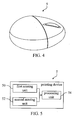
FIG. 4 is a schematic diagram illustrating a pointing device according to an embodiment of the invention. -
FIG. 5 is a block function of the pointing device shown inFIG. 4 . -
FIG. 6 is a flow chart of a method for determining the rotational angle of the pointing device shown inFIG. 4 . - Please refer to
FIG. 4 and FIG. 5. FIG. 4 is a schematic diagram illustrating apointing device 5 according to an embodiment of the invention.FIG. 5 is a block function of thepointing device 5 shown inFIG. 4 . Depending on practical application, the pointing device of the invention can be a mouse, a joystick, a trackball, etc. Thepointing device 5 shown inFIG. 4 is, but not limited to, a mouse. - As shown in
FIG. 5 , thepointing device 5 includes afirst sensing unit 50, asecond sensing unit 52, and aprocessing unit 54. Thefirst sensing unit 50 and thesecond sensing unit 52 are respectively coupled to theprocessing unit 54. In this embodiment, thefirst sensing unit 50 can be a gyroscope or other rotational sensing unit. Thesecond sensing unit 52 can be a G sensor or a magnetic sensor. - When the user rotates the
pointing device 5 to change the inclined angle, thefirst sensing unit 50 can sense the first rotational angle of thepointing device 5 relative to the absolute coordinate system (shown inFIG. 1 ). Alternatively, the first rotational angle is a relative rotational angle. For example, thefirst sensing unit 50 is a gyroscope, and the gyroscope senses a variation of angular velocity of thepointing device 5 relative to the absolute coordinate system to derive the first rotational angle. - Additionally, when the user rotates the
pointing device 5, meanwhile thesecond sensing unit 52 senses the second rotational angle of thepointing device 5 relative to the absolute coordinate system. Alternatively, the second rotational angle is an absolute rotational angle. For example, thesecond sensing unit 52 is a G sensor, and the G sensor senses a variation of the gravity force of thepointing device 5 relative to the absolute coordinate system to derive the second rotational angle. Another way is if thesecond sensing unit 52 is a magnetic sensor, the magnetic sensor sense a variation of the magnetic force of the pointing device relative to the absolute coordinate system to derive the second rotational angle. - Please refer to
FIG. 5 . Theprocessing unit 54 is utilized for receiving the first rotational angle sensed by thefirst sensing unit 50 and the second rotational angle sensed by thesecond sensing unit 52. Afterward, the processing unit calculates the absolute difference between the first and the second rotational angle, and judges whether the absolute difference is smaller than a predetermined threshold. When the judgment result is YES, alternatively, the absolute difference is smaller than the predetermined threshold, theprocessing unit 54 outputs the first rotational angle as a control signal for controlling the movement of a cursor. Contrarily, when the judgment result is NO, that is the absolute difference is larger than or equal to the predetermined threshold, theprocessing unit 54 calibrates the first rotational angle by the second rotational angle. Then, theprocessing unit 54 outputs a calibrated rotational angle as a control signal for controlling the movement of a cursor. - In this embodiment, the aforesaid calibrated rotational angle can be calculated from the following equation.

- A_out is the calibrated rotational angle; A1 is the first rotational angle; W1 is a first weight; A2 is the second rotational angle; W2 is a second weight. The first weight W1 and the second weight W2 can be changed by the designer. Preferably, the first weight W1 can be designed to, but not limited to, be larger than the second weight.
- For example, the first rotational angle sensed by the
first sensing unit 50 is 10 degrees, the second rotational angle sensed by thesecond sensing unit 52 is 9 degrees, and the predetermined threshold is 3 degrees. The absolute difference between the first rotational angle and the second rotational angle is 1 degree and smaller than the predetermined threshold, so theprocessing 54 outputs the first rotational angle (i.e. 10 degrees) as a control signal for controlling the movement of a cursor. - If the first rotational angle sensed by the
first sensing unit 50 is 10 degrees, the second rotational angle sensed by thesecond sensing unit 52 is 5 degrees, and the predetermined threshold is 3 degrees. The absolute difference between the first rotational angle and the second rotational angle is 5 degree and larger than the predetermined threshold, so theprocessing 54 calibrates the first rotational angle according to the aforesaid equation one, and outputs a calibrated rotational angle as a control signal for controlling the movement of a cursor. If the first weight W1 is 2, and the second weight W2 is 1, the calibrated rotational angle is calculated to be 8.33. - Additionally, before the
pointing device 5 of the invention is used, the user configures thefirst sensing unit 50 to return to zero, such that the movement control can be more accurate. For example, if the output value of thefirst sensing unit 50 is zero, it means that thefirst sensing unit 50 holds still. Meanwhile, the output value of thesecond sensing unit 52 is recorded for calibration. In other embodiments, thepointing device 5 can be returned to zero by other methods. For example, the output value of thesecond sensing unit 52 keeps the same during a period of time (e.g. 10 seconds), and the output value of thesecond sensing unit 52 at that time can be used for calibration. - Please refer to
FIG. 6. FIG. 6 is a flow chart of a method for determining the rotational angle of thepointing device 5 shown inFIG. 4 . At first, step S10 is performed to sense the first rotational angle of thepointing device 5 relative to the absolute coordinate system. Meanwhile, step S12 is performed to sense the second rotational angle of thepointing device 5 relative to the absolute coordinate system. Afterwards, step S 14 is performed to calculate the absolute difference between the first rotational angle and the second rotational angle. Then, step S16 is performed to judge whether the absolute difference is smaller than a predetermined threshold. If the judgment result of the step S16 is YES,step S 18 is performed to output the first rotational angle. If the judgment result of the step S16 is NO, step S20 is performed to calibrate the first rotational angle by the second rotational angle. Then, step S22 is performed to output the calibrated rotational angle. - If the
first sensing unit 50 of the pointing device5 is a gyroscope, the step S10 is performed to sense the variation of the angular velocity of the pointing device relative to the absolute coordinate system to derive the first rotational angle. If thesecond sensing unit 52 of thepointing device 5 is a G sensor, the step S12 is performed to sense the variation of the gravity force of thepointing device 5 relative to the absolute coordinate system to derive the second rotational angle. If thesecond sensing unit 52 of thepointing device 5 is a magnetic sensor, the step S12 is performed to sense the variation of the magnetic force relative to the coordinate system to derive the second rotational angle. - In other words, depending on practical application, the pointing device of the invention utilizes the gyroscope or other rotational sensing unit to cooperate with the G sensor or the magnetic sensor.
- Compared with prior art, the pointing device of the invention utilizes two sensing units to calculate and calibrate the rotational angle of the pointing device. When the difference between the first and the second rotational angle is in a tolerable range, the pointing device of the invention outputs the first rotational angle. When the difference between the first rotational angle and the second rotational angle is too large, the pointing device calibrates the first rotational angle by the second rotational angle to output a calibrated rotational angle. Accordingly, the resolution of the movement control can be highly raised.
- With the example and explanations above, the features and spirits of the invention will be hopefully well described. Those skilled in the art will readily observe that numerous modifications and alterations of the device may be made while retaining the teaching of the invention. Accordingly, the above disclosure should be construed as limited only by the metes and bounds of the appended claims.
- The invention discloses a pointing device comprising a first sensing unit, a second sensing unit and a processing unit. The first sensing unit is utilized for sensing a first rotational angle of the pointing device relative to an absolute coordinate system. The second sensing unit is utilized for sensing a second rotational angle of the pointing device relative to the absolute coordinate system. The processing unit is utilized for receiving the first and second rotational angles, calculating an absolute difference between the first and second rotational angles and judging whether the absolute difference is smaller than a predetermined threshold. If it is YES, the processing unit outputs the first rotational angle; otherwise, the processing unit calibrates the first rotational angle by the second rotational angle and then outputs the calibrated rotational angle.
Claims (12)
- A pointing device, comprising:a first sensing unit, for sensing a first rotational angle of the pointing device relative to an absolute coordinate system;a second sensing unit, for sensing a second rotational angle of the pointing device relative to the absolute coordinate system; anda processing unit, coupled to the first sensing unit and the second sensing unit respectively, for receiving the first rotational angle and the second rotational angle, and calculating an absolute difference between the first rotational angle and the second rotational angle, when the processing unit determines that the absolute difference is larger than a predetermined threshold, the processing unit calibrating the first rotational angle according to the second rotational angle and outputting a calibrated rotational angle.
- The pointing device of claim 1, wherein the first sensing unit is a gyroscope, for sensing a variation of an angular velocity of the pointing device relative to the absolute coordinate system to output the first rotational angle.
- The pointing device of claim 1, wherein the second sensing unit is a G sensor, for sensing a variation of a gravity force of the pointing device relative to the absolute coordinate system to derive the second rotational angle.
- The pointing device of claim 1, wherein the second sensing unit is a magnetic sensor, for sensing a variation of a magnetic force of the pointing device relative to the absolute coordinate system to derive the second rotational angle.
- The pointing device of claim 1, wherein the calibrated rotational angle is calculated from the following equation:

- The pointing device of claim 5, wherein the first weight is larger than the second weight.
- A method for determining a rotational angle of a pointing device, comprising the following steps of:sensing a first rotational angle of the pointing device relative to an absolute coordinate system;sensing a second rotational angle of the pointing device relative to the absolute coordinate system;calculating an absolute difference between the first rotational angle and the second rotational angle; andwhen the absolute difference is larger than a predetermined threshold, calibrating the first rotational angle according to the second rotational angle and outputting a calibrated rotational angle.
- The method of claim 7, wherein the first rotational angle is derived from a variation of an angular velocity of the pointing device relative to the coordinate system.
- The method of claim 7, wherein the second rotational angle is derived from a variation of an gravity force of the pointing device relative to the coordinate system.
- The method of claim 7, wherein the second rotational angle is derived from a variation of an magnetic force of the pointing device relative to the coordinate system.
- The method of claim 7, wherein the calibrated rotational angle is calculated from the following equation:

- The method of claim 11, wherein the first weight is larger than the second weight.
Applications Claiming Priority (1)
| Application Number | Priority Date | Filing Date | Title |
|---|---|---|---|
| TW097120029A TWI360068B (en) | 2008-05-30 | 2008-05-30 | Pointing device and method for determining rotatio |
Publications (1)
| Publication Number | Publication Date |
|---|---|
| EP2128744A2 true EP2128744A2 (en) | 2009-12-02 |
Family
ID=40627558
Family Applications (1)
| Application Number | Title | Priority Date | Filing Date |
|---|---|---|---|
| EP09004472A Withdrawn EP2128744A2 (en) | 2008-05-30 | 2009-03-27 | Pointing device and method for determining rotational angle of pointing device |
Country Status (3)
| Country | Link |
|---|---|
| US (1) | US20090299686A1 (en) |
| EP (1) | EP2128744A2 (en) |
| TW (1) | TWI360068B (en) |
Cited By (1)
| Publication number | Priority date | Publication date | Assignee | Title |
|---|---|---|---|---|
| TWI509271B (en) * | 2013-12-09 | 2015-11-21 | Voltafield Technology Corp | Magnetic sensors and electronic compass using the same |
Families Citing this family (11)
| Publication number | Priority date | Publication date | Assignee | Title |
|---|---|---|---|---|
| TWI447356B (en) * | 2011-05-27 | 2014-08-01 | Sitronix Technology Corp | Direction sensing device |
| CN102981646B (en) * | 2012-12-10 | 2016-03-30 | 江苏惠通集团有限责任公司 | Attitude sensing equipment output control method, display control method and device, system |
| TWI491902B (en) * | 2013-07-29 | 2015-07-11 | Ite Tech Inc | Heading calibration method and compass sensor using the same |
| TWI556142B (en) * | 2015-10-07 | 2016-11-01 | 原相科技股份有限公司 | Navigation trace calibrating method and related optical navigation device |
| EP4141623B1 (en) | 2017-04-27 | 2024-05-29 | Magic Leap, Inc. | Augmented reality system comprising light-emitting user input device |
| KR102122600B1 (en) | 2018-03-07 | 2020-06-12 | 매직 립, 인코포레이티드 | Visual tracking of peripheral devices |
| USD930614S1 (en) | 2018-07-24 | 2021-09-14 | Magic Leap, Inc. | Totem controller having an illumination region |
| USD918176S1 (en) | 2018-07-24 | 2021-05-04 | Magic Leap, Inc. | Totem controller having an illumination region |
| KR102696593B1 (en) * | 2019-03-26 | 2024-08-21 | 삼성전자주식회사 | Input Device and Electronic Device which interact with the Input Device |
| TWI790843B (en) * | 2021-12-06 | 2023-01-21 | 群光電子股份有限公司 | Input device and control method thereof |
| CN116263625A (en) * | 2021-12-13 | 2023-06-16 | 群光电子股份有限公司 | Input device and control method thereof |
Family Cites Families (2)
| Publication number | Priority date | Publication date | Assignee | Title |
|---|---|---|---|---|
| US5902968A (en) * | 1996-02-20 | 1999-05-11 | Ricoh Company, Ltd. | Pen-shaped handwriting input apparatus using accelerometers and gyroscopes and an associated operational device for determining pen movement |
| KR100571795B1 (en) * | 2004-02-06 | 2006-04-18 | 삼성전자주식회사 | Geomagnetic sensor and its method supporting dip detection |
-
2008
- 2008-05-30 TW TW097120029A patent/TWI360068B/en active
-
2009
- 2009-03-27 US US12/413,083 patent/US20090299686A1/en not_active Abandoned
- 2009-03-27 EP EP09004472A patent/EP2128744A2/en not_active Withdrawn
Cited By (1)
| Publication number | Priority date | Publication date | Assignee | Title |
|---|---|---|---|---|
| TWI509271B (en) * | 2013-12-09 | 2015-11-21 | Voltafield Technology Corp | Magnetic sensors and electronic compass using the same |
Also Published As
| Publication number | Publication date |
|---|---|
| TW200949625A (en) | 2009-12-01 |
| TWI360068B (en) | 2012-03-11 |
| US20090299686A1 (en) | 2009-12-03 |
Similar Documents
| Publication | Publication Date | Title |
|---|---|---|
| US20090299686A1 (en) | Pointing device and method for determining rotational angle of pointing device | |
| EP2353064B1 (en) | Method and device for inputting force intensity and rotation intensity based on motion sensing | |
| US7333087B2 (en) | Method of adjusting pointing position during click operation and 3D input device using the same | |
| US8654077B2 (en) | Apparatus and method for detecting tap | |
| EP2828675B1 (en) | Method and device for pose tracking using vector magnetometers | |
| KR100552688B1 (en) | Attitude compensation method and apparatus of inertial navigation system, method and apparatus for calculating position of inertial navigation system using same | |
| US8199031B2 (en) | Input apparatus, control apparatus, control system, control method, and program therefor | |
| EP1593931A4 (en) | Difference correcting method for posture determining instrument and motion measuring instrument | |
| US20140371906A1 (en) | Method and Apparatus for Controlling a Robotic Device via Wearable Sensors | |
| CN112394377B (en) | Navigation method, device, electronic device and storage medium | |
| CA3086559C (en) | Method for predicting a motion of an object, method for calibrating a motion model, method for deriving a predefined quantity and method for generating a virtual reality view | |
| CN102331873B (en) | Touch point tracking, positioning and correcting method and system | |
| CN104423566B (en) | Gesture recognition method and wearable device | |
| US20230213549A1 (en) | Virtual Reality System with Modeling Poses of Tracked Objects by Predicting Sensor Data | |
| CN107796387A (en) | Localization method, positioner and electronic equipment | |
| KR20200092456A (en) | Apparatus and method of correcting touch sensor input | |
| US20230213342A1 (en) | Systems and methods for stabilizing magnetic field of inertial measurement unit | |
| JP3560418B2 (en) | Pen-type input device | |
| CN101593037A (en) | Pointing device and method for determining rotation angle of pointing device | |
| JP5125534B2 (en) | Direction detection device and direction detection program | |
| CN103425308B (en) | Touch device and touch point position calibration method thereof | |
| CN112148139A (en) | Gesture recognition method and computer readable storage medium | |
| CN102183232A (en) | Orientation sensor | |
| KR100940095B1 (en) | Pointer movement value calculation device, pointer movement value correction method and posture angle variation correction method, three-dimensional pointing device using the same | |
| EP2965177B1 (en) | Using portable electronic devices for user input on a computer |
Legal Events
| Date | Code | Title | Description |
|---|---|---|---|
| PUAI | Public reference made under article 153(3) epc to a published international application that has entered the european phase |
Free format text: ORIGINAL CODE: 0009012 |
|
| 17P | Request for examination filed |
Effective date: 20090327 |
|
| AK | Designated contracting states |
Kind code of ref document: A2 Designated state(s): AT BE BG CH CY CZ DE DK EE ES FI FR GB GR HR HU IE IS IT LI LT LU LV MC MK MT NL NO PL PT RO SE SI SK TR |
|
| AX | Request for extension of the european patent |
Extension state: AL BA RS |
|
| STAA | Information on the status of an ep patent application or granted ep patent |
Free format text: STATUS: THE APPLICATION HAS BEEN WITHDRAWN |
|
| 18W | Application withdrawn |
Effective date: 20120423 |