EP2128497A1 - Method for monitoring a gear-change operation in a motor vehicle provided with a dual-clutch transmission - Google Patents
Method for monitoring a gear-change operation in a motor vehicle provided with a dual-clutch transmission Download PDFInfo
- Publication number
- EP2128497A1 EP2128497A1 EP08425383A EP08425383A EP2128497A1 EP 2128497 A1 EP2128497 A1 EP 2128497A1 EP 08425383 A EP08425383 A EP 08425383A EP 08425383 A EP08425383 A EP 08425383A EP 2128497 A1 EP2128497 A1 EP 2128497A1
- Authority
- EP
- European Patent Office
- Prior art keywords
- gear
- dis
- velocity
- angular velocity
- disengaged
- Prior art date
- Legal status (The legal status is an assumption and is not a legal conclusion. Google has not performed a legal analysis and makes no representation as to the accuracy of the status listed.)
- Granted
Links
Images


Classifications
-
- F—MECHANICAL ENGINEERING; LIGHTING; HEATING; WEAPONS; BLASTING
- F16—ENGINEERING ELEMENTS AND UNITS; GENERAL MEASURES FOR PRODUCING AND MAINTAINING EFFECTIVE FUNCTIONING OF MACHINES OR INSTALLATIONS; THERMAL INSULATION IN GENERAL
- F16H—GEARING
- F16H59/00—Control inputs to control units of change-speed- or reversing-gearings for conveying rotary motion
- F16H59/68—Inputs being a function of gearing status
- F16H59/70—Inputs being a function of gearing status dependent on the ratio established
-
- F—MECHANICAL ENGINEERING; LIGHTING; HEATING; WEAPONS; BLASTING
- F16—ENGINEERING ELEMENTS AND UNITS; GENERAL MEASURES FOR PRODUCING AND MAINTAINING EFFECTIVE FUNCTIONING OF MACHINES OR INSTALLATIONS; THERMAL INSULATION IN GENERAL
- F16H—GEARING
- F16H59/00—Control inputs to control units of change-speed- or reversing-gearings for conveying rotary motion
- F16H59/68—Inputs being a function of gearing status
- F16H59/70—Inputs being a function of gearing status dependent on the ratio established
- F16H2059/706—Monitoring gear ratio in stepped transmissions, e.g. by calculating the ratio from input and output speed
-
- F—MECHANICAL ENGINEERING; LIGHTING; HEATING; WEAPONS; BLASTING
- F16—ENGINEERING ELEMENTS AND UNITS; GENERAL MEASURES FOR PRODUCING AND MAINTAINING EFFECTIVE FUNCTIONING OF MACHINES OR INSTALLATIONS; THERMAL INSULATION IN GENERAL
- F16H—GEARING
- F16H59/00—Control inputs to control units of change-speed- or reversing-gearings for conveying rotary motion
- F16H59/36—Inputs being a function of speed
- F16H59/38—Inputs being a function of speed of gearing elements
-
- F—MECHANICAL ENGINEERING; LIGHTING; HEATING; WEAPONS; BLASTING
- F16—ENGINEERING ELEMENTS AND UNITS; GENERAL MEASURES FOR PRODUCING AND MAINTAINING EFFECTIVE FUNCTIONING OF MACHINES OR INSTALLATIONS; THERMAL INSULATION IN GENERAL
- F16H—GEARING
- F16H61/00—Control functions within control units of change-speed- or reversing-gearings for conveying rotary motion ; Control of exclusively fluid gearing, friction gearing, gearings with endless flexible members or other particular types of gearing
- F16H61/68—Control functions within control units of change-speed- or reversing-gearings for conveying rotary motion ; Control of exclusively fluid gearing, friction gearing, gearings with endless flexible members or other particular types of gearing specially adapted for stepped gearings
- F16H61/684—Control functions within control units of change-speed- or reversing-gearings for conveying rotary motion ; Control of exclusively fluid gearing, friction gearing, gearings with endless flexible members or other particular types of gearing specially adapted for stepped gearings without interruption of drive
- F16H61/688—Control functions within control units of change-speed- or reversing-gearings for conveying rotary motion ; Control of exclusively fluid gearing, friction gearing, gearings with endless flexible members or other particular types of gearing specially adapted for stepped gearings without interruption of drive with two inputs, e.g. selection of one of two torque-flow paths by clutches
Definitions
- the present invention relates to a method for monitoring a gear-change operation in a motor vehicle provided with an engine whose crankshaft is connected to a transmission having a gearbox comprising first and second primary shafts connectable to the crankshaft of the engine by respective friction clutches controlled by corresponding actuators, and a secondary or output shaft connectable to the primary shafts by gears defining a plurality of velocity ratios or gears.
- the method according to the invention essentially comprises the operation of verifying and validating the detection of the disengagement of a previously engaged gear by detecting the angular velocity of the primary shaft corresponding to said gear to be disengaged, and comparing the detected value of said angular velocity with at least one reference angular velocity.
- E is the engine of a motor vehicle.
- the engine E has a crankshaft ES which, in operation, rotates at an angular velocity ⁇ E and develops a torque C E .
- the engine E is associated with a moment of inertia J E .
- crankshaft ES of the engine E is connected to a transmission denoted by the general reference T.
- the transmission T comprises a gearbox with first and second primary shafts S1 and S2, which are connectable to the crankshaft ES of the engine E by respective friction clutches FC1 and FC2 controlled by corresponding actuators A1 and A2, which may for example be electrically controlled actuators.
- the gearbox GS also comprises a secondary or output shaft SS connectable to the primary shafts S1 and S2 by gears G1, G2 defining a plurality of velocity ratios or gears. In the simplified schematic view of figure 1 only two of these gears are shown.
- the clutches A1 and A2 are each capable of transmitting respective torques to the associated primary shafts S 1 and S2.
- This invention provides a method for monitoring a gear-change operation.
- the gear change to be monitored will be from a previously engaged gear, in the branch of the transmission containing primary shaft S1, to a new gear in the branch containing primary shaft S2.
- C F,dis is the torque transmitted by friction clutch FC1 to that branch of the transmission T in which the change of gear requires disengaging the previously engaged gear.
- C F,inn is the torque transmitted by friction clutch FC2 to the branch of the transmission T of the new gear to be engaged.
- ⁇ p,dis and ⁇ p,inn are the angular velocities of the two primary shafts S1 and S2, respectively t dis and t inn are the transmission ratios produced by gears G1 and G2, respectively, in the branches of the transmission T where the gear-change operation requires disengaging the previously engaged gear, and engaging the new gear, respectively.
- ⁇ s is the angular velocity of the secondary shaft SS.
- the detection of the disengagement of the previously engaged gear is, in the method of the invention, conveniently verified and validated in one of the various ways described below.
- the verification and validation of the detection of the disengagement of the previously engaged gear are based on detecting the angular velocity ⁇ p,dis of the primary shaft (S1 in the example shown in figure 1 ) corresponding to the gear to be disengaged, and comparing the detected value of this angular velocity with at least one reference angular velocity.
- the angular velocity ⁇ p,dis of the primary shaft (S1) corresponding to the gear to be disengaged is compared with a reference velocity corresponding to the angular velocity ⁇ s of the secondary shaft SS multiplied by the transmission ratio t dis of this primary shaft S 1 to the secondary shaft, corresponding to the gear to be disengaged.
- the disengagement of the gear is confirmed when the difference between the velocity ⁇ p,dis of the primary shaft and said reference velocity ⁇ s t dis has an absolute value greater than a predetermined value.
- the velocity ⁇ p,dis can be measured by a known type of sensor such as a phonic wheel.
- the velocity ⁇ s of the secondary shaft can also be detected by a sensor, or can be calculated from the measured angular velocities of the driving wheels, taking into account the transmission ratio at the axle.
- the verification used in the first embodiment described above is advantageously done by suitably taking into consideration the value of the torque C F,dis transmitted by the clutch (FC1) connected to the velocity ratio or gear to be disengaged.
- the angular velocity ⁇ p,dis of the primary shaft corresponding to the gear to be disengaged is compared with a reference velocity corresponding to the angular velocity ⁇ E of the crankshaft ES of the engine E.
- the disengagement of the previously engaged gear is confirmed when the velocity ⁇ p,dis is equal to this reference velocity, and the torque C F,dis transmitted by the clutch (FC1) connected to the gear to be disengaged is greater than a predetermined threshold value.
- the angular velocity ⁇ p,dis corresponding to the gear to be disengaged is compared with a first reference velocity and a second reference velocity, these being calculated by a first mathematical model and a second mathematical model, respectively, which describe the transmission T in the conditions in which said gear is engaged and disengaged, respectively.
- determination of these reference velocities, written ⁇ ref1 and ⁇ ref2 takes place in two units which in this figure are labelled C and D, respectively.
- the reference velocity ⁇ ref1 may be equal to the product of the velocity ⁇ s of the secondary shaft SS and the transmission ratio t dis corresponding to the gear to be disengaged, while the reference velocity ⁇ ref2 may be equal to the angular velocity ⁇ E of the crankshaft ES of the engine E.
- the velocity ⁇ p,dis of the primary shaft corresponding to the gear to be disengaged is compared, in a logical evaluation unit EB, with the reference velocities ⁇ ref1 and ⁇ ref2 .
- the disengagement of the previously engaged gear is confirmed when the angular velocity ⁇ p,dis satisfies a condition of predetermined congruency relative to the reference velocities ⁇ ref1 and ⁇ ref2 .
- Synchronizing the velocity ⁇ E of the crankshaft of the engine E with that of the primary shaft of the gear to be disengaged also facilitates operations in which two gear changes are required in succession.
- ⁇ E and the angular velocity of the primary shaft of the gear to be disengaged are not synchronized at the end of the first gear change, the second gear change request would have to be dealt with by making said primary shaft perform a greater velocity jump, which would increase the load on the associated synchronizer.
Landscapes
- Engineering & Computer Science (AREA)
- General Engineering & Computer Science (AREA)
- Mechanical Engineering (AREA)
- Control Of Transmission Device (AREA)
Abstract
The method comprises the operation of verifying and validating the detection of the disengagement of the previously engaged gear by detecting the angular velocity (ωp,dis) of the primary shaft (S1) corresponding to the gear to be disengaged, and comparing the detected value of said angular velocity (ωp,dis) with at least one reference angular velocity (ωref).
Description
- The present invention relates to a method for monitoring a gear-change operation in a motor vehicle provided with an engine whose crankshaft is connected to a transmission having a gearbox comprising first and second primary shafts connectable to the crankshaft of the engine by respective friction clutches controlled by corresponding actuators, and a secondary or output shaft connectable to the primary shafts by gears defining a plurality of velocity ratios or gears.
- The method according to the invention essentially comprises the operation of verifying and validating the detection of the disengagement of a previously engaged gear by detecting the angular velocity of the primary shaft corresponding to said gear to be disengaged, and comparing the detected value of said angular velocity with at least one reference angular velocity.
- Other features and advantages of the invention will be found in the following detailed description, which is given purely by way of non-limiting example with reference to the appended drawings, in which:
-
figure 1 is a simplified schematic view of a transmission with a dual-clutch gearbox; -
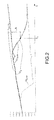
figure 2 is a series of curves showing examples, as a function of time t shown on the horizontal axis, of various values (angular velocities) during a gear change in the drive line depicted infigure 1 ; and -
figure 3 is a schematic view of an embodiment of the method according to the present invention. - In
figure 1 , E is the engine of a motor vehicle. The engine E has a crankshaft ES which, in operation, rotates at an angular velocity ωE and develops a torque CE. - The engine E is associated with a moment of inertia JE.
- The crankshaft ES of the engine E is connected to a transmission denoted by the general reference T.
- The transmission T comprises a gearbox with first and second primary shafts S1 and S2, which are connectable to the crankshaft ES of the engine E by respective friction clutches FC1 and FC2 controlled by corresponding actuators A1 and A2, which may for example be electrically controlled actuators.
- The gearbox GS also comprises a secondary or output shaft SS connectable to the primary shafts S1 and S2 by gears G1, G2 defining a plurality of velocity ratios or gears. In the simplified schematic view of
figure 1 only two of these gears are shown. - In operation, the clutches A1 and A2 are each capable of transmitting respective torques to the associated
primary shafts S 1 and S2. - This invention provides a method for monitoring a gear-change operation. In view of the following description, with reference to
figure 1 it will be assumed that the gear change to be monitored will be from a previously engaged gear, in the branch of the transmission containing primary shaft S1, to a new gear in the branch containing primary shaft S2. - In
figure 1 , CF,dis is the torque transmitted by friction clutch FC1 to that branch of the transmission T in which the change of gear requires disengaging the previously engaged gear. CF,inn, on the other hand, is the torque transmitted by friction clutch FC2 to the branch of the transmission T of the new gear to be engaged.
ω p,dis and ωp,inn are the angular velocities of the two primary shafts S1 and S2, respectively
tdis and tinn are the transmission ratios produced by gears G1 and G2, respectively, in the branches of the transmission T where the gear-change operation requires disengaging the previously engaged gear, and engaging the new gear, respectively.
ω s is the angular velocity of the secondary shaft SS. - When monitoring a change of gear it is important to detect the disengagement of the previously engaged gear. This can easily be done by analysing the signals supplied by sensors measuring the positions of the gears of the synchronizers of the transmission T.
- The detection of the disengagement of the previously engaged gear is, in the method of the invention, conveniently verified and validated in one of the various ways described below.
- In general terms, the verification and validation of the detection of the disengagement of
the previously engaged gear are based on detecting the angular velocity ωp,dis of the primary shaft (S1 in the example shown infigure 1 ) corresponding to the gear to be disengaged, and comparing the detected value of this angular velocity with at least one reference angular velocity. - In a first embodiment, the angular velocity ωp,dis of the primary shaft (S1) corresponding to the gear to be disengaged is compared with a reference velocity corresponding to the angular velocity ωs of the secondary shaft SS multiplied by the transmission ratio tdis of this
primary shaft S 1 to the secondary shaft, corresponding to the gear to be disengaged. The disengagement of the gear is confirmed when the difference between the velocity ωp,dis
of the primary shaft and said reference velocity ωstdis has an absolute value greater than a predetermined value. - Referring to the top curve in
figure 2 , such a condition is satisfied from and after the instant marked t1 in that figure, in which the difference between ωp,dis and tdisωs becomes greater than a predetermined value A. - The velocity ωp,dis can be measured by a known type of sensor such as a phonic wheel.
Similarly, the velocity ωs of the secondary shaft can also be detected by a sensor, or can be calculated from the measured angular velocities of the driving wheels, taking into account the transmission ratio at the axle. - The verification used in the first embodiment described above is advantageously done by suitably taking into consideration the value of the torque CF,dis transmitted by the clutch (FC1) connected to the velocity ratio or gear to be disengaged.
- In a second embodiment, the angular velocity ωp,dis of the primary shaft corresponding to the gear to be disengaged is compared with a reference velocity corresponding to the angular velocity ωE of the crankshaft ES of the engine E. The disengagement of the
previously engaged gear is confirmed when the velocity ωp,dis is equal to this reference velocity, and the torque CF,dis transmitted by the clutch (FC1) connected to the gear to be disengaged is greater than a predetermined threshold value. - In another embodiment shown in the illustrative schematic,
figure 3 , the angular velocity ωp,dis corresponding to the gear to be disengaged is compared with a first reference velocity and a second reference velocity, these being calculated by a first mathematical model and a second mathematical model, respectively, which describe the transmission T in the conditions in which said gear is engaged and disengaged, respectively. Referring tofigure 3 , determination of these reference velocities, written ωref1 and ωref2, takes place in two units which in this figure are labelled C and D, respectively. - As an example, the reference velocity ωref1 may be equal to the product of the velocity ωs of the secondary shaft SS and the transmission ratio tdis corresponding to the gear to be disengaged, while the reference velocity ωref2 may be equal to the angular velocity ωE of the crankshaft ES of the engine E.
- The velocity ωp,dis of the primary shaft corresponding to the gear to be disengaged is compared, in a logical evaluation unit EB, with the reference velocities ωref1 and ωref2. The disengagement of the previously engaged gear is confirmed when the angular velocity ωp,dis satisfies a condition of predetermined congruency relative to the reference velocities ωref1 and ωref2.
- The solutions described above for verifying and validating the disengagement of the "old" gear are based on the fact that the friction clutch connected to the gear to be disengaged is brought partially into contact, producing an advantageous action on completion of the gear-change operation. The reason for this is that the partial contact or partial closure of the friction clutch on the branch of the transmission T containing the gear to be disengaged, helps to synchronize, immediately after disengagement of the "old" gear, the angular velocity of the crankshaft of the engine E with that of the primary shaft of the gear to be disengaged, and thus obviates the need to perform this synchronization at the end of the operation.
- Synchronizing the velocity ωE of the crankshaft of the engine E with that of the primary shaft of the gear to be disengaged also facilitates operations in which two gear changes are
required in succession. In such operations, if ωE and the angular velocity of the primary shaft of the gear to be disengaged are not synchronized at the end of the first gear change, the second gear change request would have to be dealt with by making said primary shaft perform a greater velocity jump, which would increase the load on the associated synchronizer. - Naturally, without departing from the principle of the invention, the embodiments and details of construction may differ substantially from those described and illustrated purely by way of non-limiting example, without thereby departing from the scope of the invention as defined in the appended claims.
Claims (4)
- Method for monitoring a gear-change operation in a motor vehicle provided with an engine (E) whose crankshaft (ES) is connected to a transmission (T) having a gearbox (GS) comprising first and second primary shafts (S1, S2) connectable to the crankshaft (ES) of the engine (E) by respective friction clutches (FC1, FC2) controlled by corresponding actuators (A1, A2), and a secondary or output shaft (SS) connectable to the primary shafts (S1, S2) by gears (G1, G2) defining a plurality of velocity ratios or gears; the method comprising the operation of verifying and validating the detection of the disengagement of the previously engaged gear by detecting the angular velocity (ωp,dis) of the primary shaft (S1) corresponding to the gear to be disengaged, and comparing the detected value of said angular velocity (ωp,dis) with at least one reference angular velocity (ωref).
- Method according to Claim 1, in which the angular velocity (ωp,dis) of the primary shaft (S1) corresponding to the gear to be disengaged is compared with a reference velocity corresponding to the angular velocity (ωs) of the secondary shaft (SS) multiplied by the transmission ratio (τdis) of said primary shaft (S1) to the secondary shaft (SS), corresponding to the gear to be disengaged; the disengagement of said gear being confirmed when the difference between the velocity (ωp,dis) of said primary shaft (S1) and said reference velocity (ωsτdis) has an absolute value greater than a predetermined value (A).
- Method according to Claim 1, in which the angular velocity (ωp,dis) of the primary shaft (S1) corresponding to the gear to be disengaged is compared with a reference velocity corresponding to the angular velocity (ωE) of the crankshaft (ES) of the engine (E); the disengagement of said gear being confirmed when the velocity (ωp,dis) of said primary shaft (S1) is equal to said reference velocity (ωE) and the torque (CF,dis) transmitted by the clutch (FC1) connected to said primary shaft (S1) is greater than a predetermined threshold value (B).
- Method according to Claim 1, in which the angular velocity (ωp,dis) of the primary shaft (S1) corresponding to the gear to be disengaged is compared with a first reference velocity (ωref1) and a second reference velocity (ωref2), these being calculated by a first mathematical method and a second mathematical method, respectively, which describe the transmission (T) in the conditions in which said gear is engaged and disengaged, respectively; the disengagement of said gear being confirmed when the velocity (ωp,dis) of said primary shaft (S1) satisfies a condition of predetermined congruency relative to said first and second reference velocities (ωref1, ωref2).
Priority Applications (5)
| Application Number | Priority Date | Filing Date | Title |
|---|---|---|---|
| EP08425383A EP2128497B1 (en) | 2008-05-28 | 2008-05-28 | Method for monitoring a gear-change operation in a motor vehicle provided with a dual-clutch transmission |
| EP11192451.0A EP2428701B1 (en) | 2008-05-28 | 2008-05-28 | Method for monitoring a gear-change operation in a motor vehicle provided with a dual-clutch transmission |
| AT08425383T ATE554317T1 (en) | 2008-05-28 | 2008-05-28 | METHOD FOR MONITORING A GEAR CHANGE IN A MOTOR VEHICLE WITH DUAL CLUTCH TRANSMISSION |
| US12/422,631 US8255131B2 (en) | 2008-05-28 | 2009-04-13 | Method for monitoring a gear-change operation in a motor vehicle provided with a dual-clutch transmission |
| CN2009101492036A CN101592221B (en) | 2008-05-28 | 2009-05-27 | Method for monitoring a gear-change operation in a motor vehicle provided with a dual-clutch transmission |
Applications Claiming Priority (1)
| Application Number | Priority Date | Filing Date | Title |
|---|---|---|---|
| EP08425383A EP2128497B1 (en) | 2008-05-28 | 2008-05-28 | Method for monitoring a gear-change operation in a motor vehicle provided with a dual-clutch transmission |
Related Child Applications (2)
| Application Number | Title | Priority Date | Filing Date |
|---|---|---|---|
| EP11192451.0A Division EP2428701B1 (en) | 2008-05-28 | 2008-05-28 | Method for monitoring a gear-change operation in a motor vehicle provided with a dual-clutch transmission |
| EP11192451.0 Division-Into | 2011-12-07 |
Publications (2)
| Publication Number | Publication Date |
|---|---|
| EP2128497A1 true EP2128497A1 (en) | 2009-12-02 |
| EP2128497B1 EP2128497B1 (en) | 2012-04-18 |
Family
ID=39877768
Family Applications (2)
| Application Number | Title | Priority Date | Filing Date |
|---|---|---|---|
| EP11192451.0A Not-in-force EP2428701B1 (en) | 2008-05-28 | 2008-05-28 | Method for monitoring a gear-change operation in a motor vehicle provided with a dual-clutch transmission |
| EP08425383A Not-in-force EP2128497B1 (en) | 2008-05-28 | 2008-05-28 | Method for monitoring a gear-change operation in a motor vehicle provided with a dual-clutch transmission |
Family Applications Before (1)
| Application Number | Title | Priority Date | Filing Date |
|---|---|---|---|
| EP11192451.0A Not-in-force EP2428701B1 (en) | 2008-05-28 | 2008-05-28 | Method for monitoring a gear-change operation in a motor vehicle provided with a dual-clutch transmission |
Country Status (4)
| Country | Link |
|---|---|
| US (1) | US8255131B2 (en) |
| EP (2) | EP2428701B1 (en) |
| CN (1) | CN101592221B (en) |
| AT (1) | ATE554317T1 (en) |
Families Citing this family (2)
| Publication number | Priority date | Publication date | Assignee | Title |
|---|---|---|---|---|
| JP5622050B2 (en) * | 2011-04-18 | 2014-11-12 | アイシン・エィ・ダブリュ株式会社 | Vehicle drive device |
| ES2603562T3 (en) | 2012-09-21 | 2017-02-28 | Waldemar Link Gmbh & Co. Kg | Joint implant |
Citations (3)
| Publication number | Priority date | Publication date | Assignee | Title |
|---|---|---|---|---|
| EP0857895A2 (en) * | 1997-02-05 | 1998-08-12 | Eaton Corporation | Disengagement confirmation |
| EP1271005A2 (en) * | 2001-06-18 | 2003-01-02 | Siemens VDO Automotive S.A.S. | Method and device for recognizing the shift position of gearbox |
| EP1887261A1 (en) * | 2006-08-09 | 2008-02-13 | LuK Lamellen und Kupplungsbau Beteiligungs KG | Method and device for controlling a double-clutch gearbox |
Family Cites Families (9)
| Publication number | Priority date | Publication date | Assignee | Title |
|---|---|---|---|---|
| ES2142955T3 (en) * | 1993-09-07 | 2000-05-01 | Motorola Inc | SYSTEM TO DETERMINE THE MISSING FAILURE OF AN ENGINE. |
| DE19527412A1 (en) * | 1995-07-27 | 1997-01-30 | Zahnradfabrik Friedrichshafen | Device for regulating the transmission ratio of a continuously variable transmission |
| CN1118390C (en) * | 1996-10-16 | 2003-08-20 | 大众汽车有限公司 | Method for controlling moment of torque output by automobile's driven device |
| DE19939819C1 (en) * | 1999-08-21 | 2000-11-23 | Daimler Chrysler Ag | Transmission ratio switching method for automobile transmission uses controlled operation of clutches for 2 partial drive trains for selecting new gear ratio in disengaged drive train before re-engagement |
| CN100451400C (en) * | 2004-09-18 | 2009-01-14 | 杨斌彬 | Uninterrupted power gear speed changer |
| DE102005035408A1 (en) * | 2005-07-28 | 2007-02-01 | Robert Bosch Gmbh | Method for determining cylinder-specific rotational characteristics of a shaft of an internal combustion engine |
| ITBO20050635A1 (en) * | 2005-10-21 | 2007-04-22 | Ferrari Spa | METHOD FOR THE EXECUTION OF A GEAR CHANGE IN A SERVO-CHANGE MANUAL CHANGE |
| KR100873857B1 (en) * | 2006-11-06 | 2008-12-15 | 현대자동차주식회사 | 3 → 2 shift control method before stop of automatic transmission |
| JP4768647B2 (en) * | 2007-02-27 | 2011-09-07 | 日立オートモティブシステムズ株式会社 | Variable valve operating device for internal combustion engine |
-
2008
- 2008-05-28 EP EP11192451.0A patent/EP2428701B1/en not_active Not-in-force
- 2008-05-28 AT AT08425383T patent/ATE554317T1/en active
- 2008-05-28 EP EP08425383A patent/EP2128497B1/en not_active Not-in-force
-
2009
- 2009-04-13 US US12/422,631 patent/US8255131B2/en active Active
- 2009-05-27 CN CN2009101492036A patent/CN101592221B/en not_active Expired - Fee Related
Patent Citations (3)
| Publication number | Priority date | Publication date | Assignee | Title |
|---|---|---|---|---|
| EP0857895A2 (en) * | 1997-02-05 | 1998-08-12 | Eaton Corporation | Disengagement confirmation |
| EP1271005A2 (en) * | 2001-06-18 | 2003-01-02 | Siemens VDO Automotive S.A.S. | Method and device for recognizing the shift position of gearbox |
| EP1887261A1 (en) * | 2006-08-09 | 2008-02-13 | LuK Lamellen und Kupplungsbau Beteiligungs KG | Method and device for controlling a double-clutch gearbox |
Also Published As
| Publication number | Publication date |
|---|---|
| ATE554317T1 (en) | 2012-05-15 |
| EP2428701B1 (en) | 2018-11-07 |
| US20090299584A1 (en) | 2009-12-03 |
| CN101592221B (en) | 2013-11-06 |
| CN101592221A (en) | 2009-12-02 |
| US8255131B2 (en) | 2012-08-28 |
| EP2128497B1 (en) | 2012-04-18 |
| EP2428701A1 (en) | 2012-03-14 |
Similar Documents
| Publication | Publication Date | Title |
|---|---|---|
| CN102483107B (en) | clutch contact point | |
| EP2655914B1 (en) | Method and system for calibrating an estimated clutch characteristic curve | |
| US10041584B2 (en) | Control device for transmission | |
| CN101828053B (en) | Fault detection method for motor vehicle gearbox | |
| JP5847521B2 (en) | Dual clutch automatic transmission | |
| US9611934B2 (en) | Shift control apparatus for automatic transmission | |
| JP2009243630A (en) | Clutch control device and mu correction factor calculating method | |
| CN107076227A (en) | The method of double clutch for the double clutch gearbox that is adapted to motor vehicle, the especially Half engagement point of at least one clutch of the double clutch of automatic double clutch gearbox | |
| WO2011037084A1 (en) | Shift device for vehicle | |
| JP4633165B2 (en) | Control device for automatic transmission | |
| CN107763201A (en) | Slide the shift control method and control device of double-clutch speed changer under downshift operating mode | |
| JP6189051B2 (en) | Automatic transmission | |
| EP2767816B1 (en) | Method, device, computer program and computer readable means for monitoring the wear of the syncronizers of a manual gear box | |
| CN103210230B (en) | Determination of the crosstalk behavior of a dual clutch system | |
| CN104100702B (en) | clutch slip identification system and method | |
| EP2428701B1 (en) | Method for monitoring a gear-change operation in a motor vehicle provided with a dual-clutch transmission | |
| CN103765053B (en) | double-clutch automatic transmission | |
| CN103133683A (en) | System and method for controlling a transmission | |
| JP6310777B2 (en) | transmission | |
| JP5144019B2 (en) | Twin clutch type automatic transmission and control method thereof | |
| CN110230695B (en) | A method and device for determining a dual clutch power conflict fault | |
| US11231106B2 (en) | Method for determining the engaged gear in a manual gearbox | |
| JP4101528B2 (en) | Gear stage judging device | |
| CN110651134B (en) | Method for corrected determination of frictional energy generated in a clutch during launch of a vehicle with a manual transmission | |
| CN115614467B (en) | Gear shifting control method for double-clutch transmission |
Legal Events
| Date | Code | Title | Description |
|---|---|---|---|
| PUAI | Public reference made under article 153(3) epc to a published international application that has entered the european phase |
Free format text: ORIGINAL CODE: 0009012 |
|
| AK | Designated contracting states |
Kind code of ref document: A1 Designated state(s): AT BE BG CH CY CZ DE DK EE ES FI FR GB GR HR HU IE IS IT LI LT LU LV MC MT NL NO PL PT RO SE SI SK TR |
|
| AX | Request for extension of the european patent |
Extension state: AL BA MK RS |
|
| 17P | Request for examination filed |
Effective date: 20100531 |
|
| 17Q | First examination report despatched |
Effective date: 20100621 |
|
| AKX | Designation fees paid |
Designated state(s): AT BE BG CH CY CZ DE DK EE ES FI FR GB GR HR HU IE IS IT LI LT LU LV MC MT NL NO PL PT RO SE SI SK TR |
|
| GRAP | Despatch of communication of intention to grant a patent |
Free format text: ORIGINAL CODE: EPIDOSNIGR1 |
|
| RIN1 | Information on inventor provided before grant (corrected) |
Inventor name: PORTA, ATTILIO Inventor name: PREGNOLATO, GIAN LUIGI Inventor name: CORIGLIANO, EMANUEL Inventor name: OSELLA, GIANCARLO Inventor name: MONTU', MARCO |
|
| GRAS | Grant fee paid |
Free format text: ORIGINAL CODE: EPIDOSNIGR3 |
|
| GRAA | (expected) grant |
Free format text: ORIGINAL CODE: 0009210 |
|
| AK | Designated contracting states |
Kind code of ref document: B1 Designated state(s): AT BE BG CH CY CZ DE DK EE ES FI FR GB GR HR HU IE IS IT LI LT LU LV MC MT NL NO PL PT RO SE SI SK TR |
|
| REG | Reference to a national code |
Ref country code: GB Ref legal event code: FG4D |
|
| REG | Reference to a national code |
Ref country code: CH Ref legal event code: EP |
|
| REG | Reference to a national code |
Ref country code: IE Ref legal event code: FG4D |
|
| REG | Reference to a national code |
Ref country code: AT Ref legal event code: REF Ref document number: 554317 Country of ref document: AT Kind code of ref document: T Effective date: 20120515 |
|
| REG | Reference to a national code |
Ref country code: DE Ref legal event code: R096 Ref document number: 602008014892 Country of ref document: DE Effective date: 20120621 |
|
| REG | Reference to a national code |
Ref country code: NL Ref legal event code: VDEP Effective date: 20120418 |
|
| REG | Reference to a national code |
Ref country code: AT Ref legal event code: MK05 Ref document number: 554317 Country of ref document: AT Kind code of ref document: T Effective date: 20120418 |
|
| LTIE | Lt: invalidation of european patent or patent extension |
Effective date: 20120418 |
|
| PG25 | Lapsed in a contracting state [announced via postgrant information from national office to epo] |
Ref country code: IS Free format text: LAPSE BECAUSE OF FAILURE TO SUBMIT A TRANSLATION OF THE DESCRIPTION OR TO PAY THE FEE WITHIN THE PRESCRIBED TIME-LIMIT Effective date: 20120818 Ref country code: PL Free format text: LAPSE BECAUSE OF FAILURE TO SUBMIT A TRANSLATION OF THE DESCRIPTION OR TO PAY THE FEE WITHIN THE PRESCRIBED TIME-LIMIT Effective date: 20120418 Ref country code: SE Free format text: LAPSE BECAUSE OF FAILURE TO SUBMIT A TRANSLATION OF THE DESCRIPTION OR TO PAY THE FEE WITHIN THE PRESCRIBED TIME-LIMIT Effective date: 20120418 Ref country code: CY Free format text: LAPSE BECAUSE OF FAILURE TO SUBMIT A TRANSLATION OF THE DESCRIPTION OR TO PAY THE FEE WITHIN THE PRESCRIBED TIME-LIMIT Effective date: 20120418 Ref country code: NO Free format text: LAPSE BECAUSE OF FAILURE TO SUBMIT A TRANSLATION OF THE DESCRIPTION OR TO PAY THE FEE WITHIN THE PRESCRIBED TIME-LIMIT Effective date: 20120718 Ref country code: FI Free format text: LAPSE BECAUSE OF FAILURE TO SUBMIT A TRANSLATION OF THE DESCRIPTION OR TO PAY THE FEE WITHIN THE PRESCRIBED TIME-LIMIT Effective date: 20120418 Ref country code: LT Free format text: LAPSE BECAUSE OF FAILURE TO SUBMIT A TRANSLATION OF THE DESCRIPTION OR TO PAY THE FEE WITHIN THE PRESCRIBED TIME-LIMIT Effective date: 20120418 |
|
| PG25 | Lapsed in a contracting state [announced via postgrant information from national office to epo] |
Ref country code: HR Free format text: LAPSE BECAUSE OF FAILURE TO SUBMIT A TRANSLATION OF THE DESCRIPTION OR TO PAY THE FEE WITHIN THE PRESCRIBED TIME-LIMIT Effective date: 20120418 Ref country code: PT Free format text: LAPSE BECAUSE OF FAILURE TO SUBMIT A TRANSLATION OF THE DESCRIPTION OR TO PAY THE FEE WITHIN THE PRESCRIBED TIME-LIMIT Effective date: 20120820 Ref country code: SI Free format text: LAPSE BECAUSE OF FAILURE TO SUBMIT A TRANSLATION OF THE DESCRIPTION OR TO PAY THE FEE WITHIN THE PRESCRIBED TIME-LIMIT Effective date: 20120418 Ref country code: GR Free format text: LAPSE BECAUSE OF FAILURE TO SUBMIT A TRANSLATION OF THE DESCRIPTION OR TO PAY THE FEE WITHIN THE PRESCRIBED TIME-LIMIT Effective date: 20120719 Ref country code: LV Free format text: LAPSE BECAUSE OF FAILURE TO SUBMIT A TRANSLATION OF THE DESCRIPTION OR TO PAY THE FEE WITHIN THE PRESCRIBED TIME-LIMIT Effective date: 20120418 |
|
| PG25 | Lapsed in a contracting state [announced via postgrant information from national office to epo] |
Ref country code: BE Free format text: LAPSE BECAUSE OF FAILURE TO SUBMIT A TRANSLATION OF THE DESCRIPTION OR TO PAY THE FEE WITHIN THE PRESCRIBED TIME-LIMIT Effective date: 20120418 Ref country code: MC Free format text: LAPSE BECAUSE OF NON-PAYMENT OF DUE FEES Effective date: 20120531 |
|
| REG | Reference to a national code |
Ref country code: CH Ref legal event code: PL |
|
| PG25 | Lapsed in a contracting state [announced via postgrant information from national office to epo] |
Ref country code: AT Free format text: LAPSE BECAUSE OF FAILURE TO SUBMIT A TRANSLATION OF THE DESCRIPTION OR TO PAY THE FEE WITHIN THE PRESCRIBED TIME-LIMIT Effective date: 20120418 Ref country code: DK Free format text: LAPSE BECAUSE OF FAILURE TO SUBMIT A TRANSLATION OF THE DESCRIPTION OR TO PAY THE FEE WITHIN THE PRESCRIBED TIME-LIMIT Effective date: 20120418 Ref country code: SK Free format text: LAPSE BECAUSE OF FAILURE TO SUBMIT A TRANSLATION OF THE DESCRIPTION OR TO PAY THE FEE WITHIN THE PRESCRIBED TIME-LIMIT Effective date: 20120418 Ref country code: CH Free format text: LAPSE BECAUSE OF NON-PAYMENT OF DUE FEES Effective date: 20120531 Ref country code: CZ Free format text: LAPSE BECAUSE OF FAILURE TO SUBMIT A TRANSLATION OF THE DESCRIPTION OR TO PAY THE FEE WITHIN THE PRESCRIBED TIME-LIMIT Effective date: 20120418 Ref country code: NL Free format text: LAPSE BECAUSE OF FAILURE TO SUBMIT A TRANSLATION OF THE DESCRIPTION OR TO PAY THE FEE WITHIN THE PRESCRIBED TIME-LIMIT Effective date: 20120418 Ref country code: LI Free format text: LAPSE BECAUSE OF NON-PAYMENT OF DUE FEES Effective date: 20120531 Ref country code: RO Free format text: LAPSE BECAUSE OF FAILURE TO SUBMIT A TRANSLATION OF THE DESCRIPTION OR TO PAY THE FEE WITHIN THE PRESCRIBED TIME-LIMIT Effective date: 20120418 Ref country code: EE Free format text: LAPSE BECAUSE OF FAILURE TO SUBMIT A TRANSLATION OF THE DESCRIPTION OR TO PAY THE FEE WITHIN THE PRESCRIBED TIME-LIMIT Effective date: 20120418 |
|
| PLBE | No opposition filed within time limit |
Free format text: ORIGINAL CODE: 0009261 |
|
| STAA | Information on the status of an ep patent application or granted ep patent |
Free format text: STATUS: NO OPPOSITION FILED WITHIN TIME LIMIT |
|
| REG | Reference to a national code |
Ref country code: IE Ref legal event code: MM4A |
|
| 26N | No opposition filed |
Effective date: 20130121 |
|
| GBPC | Gb: european patent ceased through non-payment of renewal fee |
Effective date: 20120718 |
|
| PG25 | Lapsed in a contracting state [announced via postgrant information from national office to epo] |
Ref country code: ES Free format text: LAPSE BECAUSE OF FAILURE TO SUBMIT A TRANSLATION OF THE DESCRIPTION OR TO PAY THE FEE WITHIN THE PRESCRIBED TIME-LIMIT Effective date: 20120729 Ref country code: GB Free format text: LAPSE BECAUSE OF NON-PAYMENT OF DUE FEES Effective date: 20120718 Ref country code: IE Free format text: LAPSE BECAUSE OF NON-PAYMENT OF DUE FEES Effective date: 20120528 |
|
| REG | Reference to a national code |
Ref country code: DE Ref legal event code: R097 Ref document number: 602008014892 Country of ref document: DE Effective date: 20130121 |
|
| PG25 | Lapsed in a contracting state [announced via postgrant information from national office to epo] |
Ref country code: MT Free format text: LAPSE BECAUSE OF FAILURE TO SUBMIT A TRANSLATION OF THE DESCRIPTION OR TO PAY THE FEE WITHIN THE PRESCRIBED TIME-LIMIT Effective date: 20120418 Ref country code: BG Free format text: LAPSE BECAUSE OF FAILURE TO SUBMIT A TRANSLATION OF THE DESCRIPTION OR TO PAY THE FEE WITHIN THE PRESCRIBED TIME-LIMIT Effective date: 20120718 |
|
| PG25 | Lapsed in a contracting state [announced via postgrant information from national office to epo] |
Ref country code: TR Free format text: LAPSE BECAUSE OF FAILURE TO SUBMIT A TRANSLATION OF THE DESCRIPTION OR TO PAY THE FEE WITHIN THE PRESCRIBED TIME-LIMIT Effective date: 20120418 |
|
| PG25 | Lapsed in a contracting state [announced via postgrant information from national office to epo] |
Ref country code: LU Free format text: LAPSE BECAUSE OF NON-PAYMENT OF DUE FEES Effective date: 20120528 |
|
| PG25 | Lapsed in a contracting state [announced via postgrant information from national office to epo] |
Ref country code: HU Free format text: LAPSE BECAUSE OF FAILURE TO SUBMIT A TRANSLATION OF THE DESCRIPTION OR TO PAY THE FEE WITHIN THE PRESCRIBED TIME-LIMIT Effective date: 20080528 |
|
| REG | Reference to a national code |
Ref country code: FR Ref legal event code: PLFP Year of fee payment: 9 |
|
| REG | Reference to a national code |
Ref country code: FR Ref legal event code: PLFP Year of fee payment: 10 |
|
| REG | Reference to a national code |
Ref country code: FR Ref legal event code: PLFP Year of fee payment: 11 |
|
| PGFP | Annual fee paid to national office [announced via postgrant information from national office to epo] |
Ref country code: IT Payment date: 20220506 Year of fee payment: 15 Ref country code: FR Payment date: 20220530 Year of fee payment: 15 Ref country code: DE Payment date: 20220519 Year of fee payment: 15 |
|
| REG | Reference to a national code |
Ref country code: DE Ref legal event code: R119 Ref document number: 602008014892 Country of ref document: DE |
|
| PG25 | Lapsed in a contracting state [announced via postgrant information from national office to epo] |
Ref country code: IT Free format text: LAPSE BECAUSE OF NON-PAYMENT OF DUE FEES Effective date: 20230528 Ref country code: DE Free format text: LAPSE BECAUSE OF NON-PAYMENT OF DUE FEES Effective date: 20231201 |
|
| PG25 | Lapsed in a contracting state [announced via postgrant information from national office to epo] |
Ref country code: FR Free format text: LAPSE BECAUSE OF NON-PAYMENT OF DUE FEES Effective date: 20230531 |