EP2128496A2 - Tooth belt wheel for a tooth belt drive - Google Patents
Tooth belt wheel for a tooth belt drive Download PDFInfo
- Publication number
- EP2128496A2 EP2128496A2 EP09006899A EP09006899A EP2128496A2 EP 2128496 A2 EP2128496 A2 EP 2128496A2 EP 09006899 A EP09006899 A EP 09006899A EP 09006899 A EP09006899 A EP 09006899A EP 2128496 A2 EP2128496 A2 EP 2128496A2
- Authority
- EP
- European Patent Office
- Prior art keywords
- base body
- toothed belt
- belt wheel
- toothing
- wheel
- Prior art date
- Legal status (The legal status is an assumption and is not a legal conclusion. Google has not performed a legal analysis and makes no representation as to the accuracy of the status listed.)
- Withdrawn
Links
Images


Classifications
-
- F—MECHANICAL ENGINEERING; LIGHTING; HEATING; WEAPONS; BLASTING
- F16—ENGINEERING ELEMENTS AND UNITS; GENERAL MEASURES FOR PRODUCING AND MAINTAINING EFFECTIVE FUNCTIONING OF MACHINES OR INSTALLATIONS; THERMAL INSULATION IN GENERAL
- F16H—GEARING
- F16H55/00—Elements with teeth or friction surfaces for conveying motion; Worms, pulleys or sheaves for gearing mechanisms
- F16H55/02—Toothed members; Worms
- F16H55/17—Toothed wheels
- F16H55/171—Toothed belt pulleys
-
- B—PERFORMING OPERATIONS; TRANSPORTING
- B29—WORKING OF PLASTICS; WORKING OF SUBSTANCES IN A PLASTIC STATE IN GENERAL
- B29L—INDEXING SCHEME ASSOCIATED WITH SUBCLASS B29C, RELATING TO PARTICULAR ARTICLES
- B29L2015/00—Gear wheels or similar articles with grooves or projections, e.g. control knobs
- B29L2015/003—Gears
-
- F—MECHANICAL ENGINEERING; LIGHTING; HEATING; WEAPONS; BLASTING
- F16—ENGINEERING ELEMENTS AND UNITS; GENERAL MEASURES FOR PRODUCING AND MAINTAINING EFFECTIVE FUNCTIONING OF MACHINES OR INSTALLATIONS; THERMAL INSULATION IN GENERAL
- F16H—GEARING
- F16H55/00—Elements with teeth or friction surfaces for conveying motion; Worms, pulleys or sheaves for gearing mechanisms
- F16H55/32—Friction members
- F16H55/36—Pulleys
- F16H2055/363—Pulleys with special means or properties for lateral tracking of the flexible members running on the pulley, e.g. with crowning to keep a belt on track
Definitions
- the invention relates to a toothed belt wheel for a toothed belt drive.
- the invention has for its object to provide a toothed belt for a toothed belt drive available, which can be inexpensively manufactured in as few process steps and a timing belt is safe to perform in a position.
- the main body 14 is according to the embodiments almost bottomless. From the bottom remains a maximum edge, so centrally there is a large hole.
- the main body 14 thus consists essentially only of a hollow cylindrical Wall with an inner cross section and an outer cross section.
- the inner cross section is in the in FIG. 1 and FIG. 3 illustrated embodiments in the axial direction stepwise smaller. In the embodiments of the FIGS. 2 and 4 the inner cross section is constant in the axial direction.
- a toothing 20, 200 is applied on an outer periphery 16 of the main body 14 and the wall.
- the toothing 20, 200 preferably runs parallel to the axis of the main body 14.
- the teeth 20, 200 conceivable. It must be made possible by this only a power transmission to a corresponding belt.
- it is a toothed belt with teeth perpendicular to its length.
- a roughening of the surface of the base body 14 would be sufficient.
- the toothing 20, 200 of the main body 14 is in the first two embodiments ( Fig. 1, Fig. 2 ) introduced into the base body 14 by machining.
- the toothing 20, 200 can for this purpose be introduced particularly advantageously by hobbing in the base body 14.
- a toothing 200 may be applied by a contoured plastic layer 202 on the outer circumference of the base body 14.
- the toothing 20, 200 is delimited axially on both end faces 22, 24 of the main body 14 by a flanged wheel 30, 30 ', 30 "by the completion of the toothing 20, 200 on the end faces 22, 24 of the base body 14 with the flanged wheels 30 , 30 ', 30 "ensures a secure guidance of a toothed belt.
- the toothed belt is secured by the protruding flanges 30, 30 ', 30 "from slipping.
- the flanged wheel 30, 30 ', 30 has a larger outer diameter than the base body 14 in order to allow a secure guidance of the belt, various inner diameters being possible for the flange 30, 30', 30".
- the inner diameter of the flanged wheel 30 can be approximately equal to the outer circumference of the main body 14, if the flanged wheel 30 is to be provided, for example, next to the toothing 20, 200 at the edge of the toothed belt wheel 10, 100.
- the flanged wheel 30 would thus expand an end face 22, 24 of the base body 14 radially outwardly when it is placed flush. This is in the first embodiment ( Fig. 1 ).
- the teeth 20, 200 may extend over the entire width of the base body 14. This would be particularly important if the teeth 20, 200 would be raised radially outwardly beyond the outer circumference of the main body 14, as in the third and fourth embodiments ( FIGS. 3 and 4 ) is executed.
- An inner diameter of the flanged wheel 30 approximately equal to the outer circumference of the main body 14 and a placement of the flanged wheel 30 in addition to the teeth 20, 200 namely enforce a corresponding consideration, possibly post-processing during application of the toothing.
- a third possibility for the selection of the inner diameter of the Borusion 30 " is in the fourth embodiment ( Fig. 4 ) of a toothed belt wheel 100 'executed.
- the inner diameter of the flange 30 " is smaller here than the inner diameter of the base body 14.
- the flanged wheels 30, 30 ', 30 also have the task of reinforcing the base body 14. They can be attached either by welding, by pressing or by caulking on the base body 14. For this purpose, the flanged wheels 30, 30' should be used. It is particularly advantageous, alternatively to the abovementioned variants, to spray an edge disc 30, 30 ', 30 "made of plastic on an end face 22, 24 of the main body 14 ,
- one or both flanged wheels 30, 30 ', 30' ' is applied to the base body 14 together with the contoured plastic layer 202 in one production step.
- the application of the existing plastic toothing with simultaneously integrally formed flange or flanged wheels can, for example. done by plastic injection.
- both flanged wheels When machined in the deep-drawn metal part toothing 20, 200 in the timing pulley 10 both flanged wheels must 30, 30 ', 30 "may be formed as separate parts, namely that the machining step makes it necessary for an outlet to be provided beyond the end faces 22, 24 for the milling cutter milling the toothing.
- an embodiment of the flanged wheel 30, 30 ', 30 is possible, in which the flanged wheel 30, 30', 30" is clipped into the contoured plastic layer 202.
- Another attachment of the flanged wheel 30, 30 ', 30 is given, for example, by positive locking of the flanged wheel 30, 30', 30" with the contoured plastic layer 202.
- Connections between parts made of plastic 30, 30 ', 30' ', 202 may alternatively be carried out by welding with ultrasound or with laser.
- the toothed belt 10, 100 is to transmit a force from an output shaft of a drive to a toothed belt.
- the timing pulley 10, 100 must therefore be driven directly or indirectly from the output shaft.
- the base body 14 is provided with driving cams 18, wherein the driving cams 18 protrude radially inward in the hole of the main body.
- FIGS. 1 and 3 is in each case such a driving sock 18 to see.
- the driving cams 18 can engage in corresponding contours of the output shaft of the drive.
- Frictional connections between the toothed belt 10, 100 and output shaft are alternatively executable by interference fit or other compounds.
- FIG. 7 Another in FIG. 7 illustrated embodiment of a flanged wheel 30 '''goes beyond the embodiments of the FIGS. 1 to 4 insofar as that the flanged wheel 30 '''a pot-shaped or bell-shaped base body 14 with teeth 20, 200 provides.
- Two such flanged wheels 30 '''together in coaxial arrangement form a toothed belt wheel, when their base bodies are connected to each other facing each other, so that the flanged wheels 30''' are arranged facing away from each other.
- a method for producing a toothed belt wheel 10, 10 ' comprises, as a first step, the deep-drawing of the pot-shaped or bell-shaped main body 14 made of a metal.
- a second step is the cutting introduction of the toothing 20 into the base body 14 on its outer circumference 16.
- two flanged wheels 30, 30 ', 30 are provided on the end faces 20, 24 of the base body 14.
- at least one of the flanged wheels 30, 30 ', 30 is fastened to an end face 22, 24 of the base body 14.
- a method for producing a toothed belt wheel 100, 100 ', as indicated for example with the exemplary embodiments 3 and 4, also includes deep-drawing as the first method step the pot-shaped or bell-shaped base body 14 made of a metal.
- the toothing 200 made of plastic is applied to the base body on its outer circumference 16.
- a power steering drive 60 is in the FIGS. 5 and 6 shown. In Figure 5 it is clear that the power steering drive 60 is executed paraxial.
- a drive housing 62 of the power steering drive 60 is arranged parallel to a power steering axis 64.
- the drive housing 62 includes the toothed belt wheel, which causes a force transmission to the coaxial power steering axis 64 via the toothed belt.
Abstract
Description
Die Erfindung betrifft ein Zahnriemenrad für einen Zahnriemenantrieb.The invention relates to a toothed belt wheel for a toothed belt drive.
Stand der Technik sind die Druckschriften
Der Erfindung liegt die Aufgabe zugrunde, ein Zahnriemenrad für einen Zahnriemenantrieb zur Verfügung zu stellen, welches kostengünstig in möglichst wenigen Verfahrensschritten hergestellt werden kann und einen Zahnriemen sicher zu führen in der Lage ist.The invention has for its object to provide a toothed belt for a toothed belt drive available, which can be inexpensively manufactured in as few process steps and a timing belt is safe to perform in a position.
Diese Aufgabe wird erfindungsgemäß gelöst durch ein Zahnriemenrad mit den Merkmalen des Anspruchs 1.This object is achieved by a toothed belt with the features of claim 1.
Vorteilhafte Ausführungen der Erfindung sind in den Unteransprüchen angegeben, ebenso Verfahren zur Herstellung erfindungsgemäßer Zahnriemenräder und eine Verwendung für ein solches.Advantageous embodiments of the invention are specified in the dependent claims, as well as methods for producing inventive timing pulleys and a use for such.
Im Folgenden wird die Erfindung anhand von zwei in Zeichnungen dargestellten Ausführungsbeispielen näher erläutert. Es zeigen
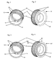
- Fig. 1
- eine perspektivische Darstellung eines ersten Ausführungsbeispiels eines Zahnriemenrads mit spanend eingebrachter Verzahnung und mit Mitnahmenocken,
- Fig. 2
- eine perspektivische Darstellung eines zweiten Ausführungsbeispiels eines Zahnriemenrads mit spanend eingebrachter Verzahnung,
- Fig. 3
- eine perspektivische Darstellung eines dritten Ausführungsbeispiels eines Zahnriemenrads mit umspritzter Verzahnung aus Kunststoff und mit Mitnahmenocken,
- Fig. 4
- eine perspektivische Darstellung eines vierten Ausführungsbeispiels eines Zahnriemenrads mit umspritzter Verzahnung aus Kunststoff,
- Fig. 5
- eine perspektivische Darstellung eines achsparallelen Servolenkungsantriebs, in dem ein erfindungsgemäßes Zahnriemenrad seine Verwendung findet,
- Fig. 6
- einen Axialschnitt durch das in dem in
Fig. 5 dargestellten Servolenkungsantrieb verwendete Zahnriemenrad mit seiner verwendungsgemäßen Umgebung und - Fig. 7
- eine Seitenansicht einer Bordscheibe mit Grundkörper.
- Fig. 1
- 1 is a perspective view of a first embodiment of a toothed belt wheel with toothed toothing and with driving cams,
- Fig. 2
- a perspective view of a second embodiment of a toothed belt wheel with toothed toothing,
- Fig. 3
- 3 is a perspective view of a third exemplary embodiment of a toothed belt wheel with an overmolded toothing made of plastic and with driving cams,
- Fig. 4
- a perspective view of a fourth embodiment of a toothed belt with molded plastic toothing,
- Fig. 5
- a perspective view of an axis-parallel power steering drive, in which a toothed belt according to the invention finds its use,
- Fig. 6
- an axial section through that in the in
Fig. 5 used power steering drive used timing belt with its environment according to the use and - Fig. 7
- a side view of a flange with body.
Den vier in den Abbildungen 1 bis 4 dargestellten Ausführungsbeispielen von Zahnriemenrädern 10, 10', 100, 100' ist ein topf- oder glockenförmiger Grundkörper 14 aus Metall als formgebendes Element gemein. Gleiche Teile sind mit gleichen Bezugszeichen bezeichnet.The four illustrated in Figures 1 to 4 embodiments of the
Der Grundkörper 14 ist den Ausführungsbeispielen entsprechend nahezu bodenlos. Von dem Boden bleibt maximal ein Rand erhalten, so dass zentral ein großes Loch vorhanden ist. Der Grundkörper 14 besteht folglich im Wesentlichen nur aus einer hohlzylindrischen Wandung mit einem inneren Querschnitt und einem äußeren Querschnitt.The
Der innere Querschnitt wird in den in
Die Verzahnung 20, 200 verläuft vorzugsweise achsparallel zum Grundkörper 14. Es sind grundsätzlich auch andere, nicht dargestellte Geometrien für die Verzahnungen 20, 200 denkbar. Es muss hierdurch lediglich eine Kraftübertragung auf einen entsprechenden Riemen ermöglicht werden. Im Falle der dargestellten Ausführungsbeispiele ist es ein Zahnriemen mit zu seiner Länge senkrechter Verzahnung. Bei einem Riemen ohne Verzahnung wäre beispielsweise eine Aufrauhung der Oberfläche des Grundkörpers 14 ausreichend.The toothing 20, 200 preferably runs parallel to the axis of the
Die Verzahnung 20, 200 des Grundkörpers 14 ist in den ersten beiden Ausführungsbeispielen (
Alternativ zum spanenden Einbringen einer Verzahnung 20 kann eine Verzahnung 200 durch eine konturierte Kunststoffschicht 202 auf den Außenumfang des Grundkörpers 14 aufgebracht sein.As an alternative to the cutting introduction of a
Dies entspricht den Ausführungsbeispielen 3 und 4 (
Die Verzahnung 20, 200 ist axial auf beiden Stirnseiten 22, 24 des Grundkörpers 14 von je einer Bordscheibe 30, 30', 30" begrenzt. Durch den Abschluss der Verzahnung 20, 200 an den Stirnseiten 22, 24 des Grundkörpers 14 mit den Bordscheiben 30, 30', 30" ist eine sichere Führung eines Zahnriemens gewährleistet. Der Zahnriemen wird durch die überstehenden Bordscheiben 30, 30', 30" vor einem Herabrutschen gesichert.The
Die Bordscheibe 30, 30', 30" hat einen größeren Außendurchmesser als der Grundkörper 14, um eine sichere Führung des Riemens zu ermöglichen. Es kommen verschiedene Innendurchmesser für die Bordscheibe 30, 30', 30" in Frage.The flanged
Der Innendurchmesser der Bordscheibe 30 kann etwa gleich dem Außenumfang des Grundkörpers 14 sein, wenn die Bordscheibe 30 beispielsweise neben der Verzahnung 20, 200 am Rand des Zahnriemenrades 10, 100 bereitgestellt sein soll. Die Bordscheibe 30 würde somit eine Stirnseite 22, 24 des Grundkörpers 14 radial nach außen erweitern, wenn sie bündig aufgesetzt wird. Dies ist im ersten Ausführungsbeispiel (
Der Innendurchmesser der Bordscheibe 30' kann auch gleich dem Innendurchmesser des Grundkörpers 14 sein, wie es im zweiten Ausführungsbeispiel (
Eine dritte Möglichkeit für die Wahl des Innendurchmessers der Borscheibe 30" ist im vierten Ausführungsbeispiel (
Die Bordscheiben 30, 30', 30" haben neben der Führung des Zahnriemens auch die Aufgabe, den Grundkörper 14 zu verstärken. Sie können entweder durch Verschweißen, durch Aufpressen oder durch Verstemmen am Grundkörper 14 angebracht sein. Dazu sollten die Bordscheiben 30, 30', 30" aus einem geeigneten Material bestehen, bspw. aus dem gleichen wie der Grundkörper 14. Besonders vorteilhaft ist es alternativ zu den vorgenannten Varianten, eine Bordscheibe 30, 30', 30" aus Kunststoff auf einer Stirnseite 22, 24 des Grundkörpers 14 anzuspritzen.In addition to the guidance of the toothed belt, the
Es liegt im Rahmen der Erfindung, dass eine oder beide Bordscheiben 30, 30', 30'' in einem Fertigungsschritt gemeinsam mit der konturierten Kunststoffschicht 202 auf den Grundkörper 14 aufgebracht wird. Das Aufbringen der aus Kunststoff bestehenden Verzahnung mit gleichzeitig einstückig angeformten Bordscheibe bzw. Bordscheiben kann z.B. durch Kunststoffumspritzen erfolgen.It is within the scope of the invention that one or both
Bei spanend in das tiefgezogene Metallteil eingebrachter Verzahnung 20, 200 in das Zahnriemenrad 10 müssen beide Bordscheiben 30, 30', 30" als separate Teile ausgebildet sein. Der Verfahrensschritt der spanenden Bearbeitung macht es nämlich notwendig, dass über die Stirnseiten 22, 24 hinaus ein Auslauf für den Fräser, der die Verzahnung fräst, gegeben ist.When machined in the deep-drawn
Durch die Wahl der konturierten Kunststoffschicht 202 als aufgebrachte Verzahnung 200 ist eine Ausführungsform der Bordscheibe 30, 30', 30" möglich, bei der die Bordscheibe 30, 30', 30" in die konturierte Kunststoffschicht 202 eingeklipst wird. Eine andere Befestigung der Bordscheibe 30, 30', 30" ist bspw. durch Formschluss der Bordscheibe 30, 30', 30" mit der konturierten Kunststoffschicht 202 gegeben. Verbindungen zwischen Teilen aus Kunststoff 30, 30', 30'', 202 können alternativ auch durch Verschweißen mit Ultraschall oder mit Laser ausgeführt sein.By choosing the contoured
Das Zahnriemenrad 10, 100 soll eine Kraft von einer Ausgangswelle eines Antriebs auf einen Zahnriemen übertragen. Das Zahnriemenrad 10, 100 muss folglich direkt oder indirekt von der Ausgangswelle angetrieben werden können. Hierzu ist bspw. der Grundkörper 14 mit Mitnahmenocken 18 versehen, wobei die Mitnahmenocken 18 im Loch des Grundkörpers radial nach innen abstehen.The
In den
Für den Fall, dass die Ausgangswelle oder ein anderes mit dem Zahnriemenrad 10, 10', 100, 100' in Wirkverbindung stehendes Element statt negativer Ausformungen zur Aufnahme von Mitnahmenocken 18 positive Erhebungen aufweist, die bspw. als Nocken ausgebildet sind, sind im Grundkörper 14 alternativ hierzu in nicht dargestellter Weise Aussparungen zur Aufnahme solcher Erhebungen vorgesehen.In the event that the output shaft or another with the
Kraftschlüssige Verbindungen zwischen Zahnriemenrad 10, 100 und Ausgangswelle sind alternativ auch durch Presspassung oder andere Verbindungen ausführbar. Besonders vorteilhaft ist bspw. eine Fixierung einer Bordscheibe mit solchen Verbindungen auf dem antreibenden Element.Frictional connections between the
Ein weiteres in
Ein Verfahren zur Herstellung eines Zahnriemenrades 10, 10' wie bspw. in den Ausführungsbeispielen 1 und 2 angegeben, weist als ersten Schritt das Tiefziehen des topf- oder glockenförmigen Grundkörpers 14 aus einem Metall auf. Ein zweiter Schritt ist das spanende Einbringen der Verzahnung 20 in den Grundkörper 14 an seinem Außenumfang 16. In einem dritten Schritt werden zwei Bordscheiben 30, 30', 30'' an den Stirnseiten 20, 24 des Grundkörpers 14 bereitgestellt. Abschließend wird mindestens eine der Bordscheiben 30, 30', 30" an einer Stirnseite 22, 24 des Grundkörpers 14 befestigt.A method for producing a
Ein Verfahren zur Herstellung eines Zahnriemenrades 100, 100', wie etwa mit den Ausführungsbeispielen 3 und 4 angegeben, weist als ersten Verfahrensschritt ebenfalls das Tiefziehen des topf- oder glockenförmigen Grundkörpers 14 aus einem Metall auf. In einem zweiten Verfahrensschritt wird die Verzahnung 200 aus Kunststoff auf den Grundkörper an seinem Außenumfang 16 aufgebracht. In einem dritten Verfahrensschritt wird mindestens eine Bordscheibe 30, 30', 30'' an den Stirnseiten 22, 24 des Grundkörpers 14 bereitgestellt, wonach abschließend in einem vierten Verfahrensschritt mindestens eine Bordscheibe 30, 30', 30" an einer der Stirnseiten des Grundkörpers 14 befestigt wird.A method for producing a
Die Zahnriemenräder 10, 10', 100, 100' und das zuletzt beschriebene Zahnriemenrad bestehend aus zwei Bordscheiben 30''' werden vorzugsweise in Servolenkungsantrieben verwendet. Solch ein Servolenkungsantrieb 60 ist in den
- 10, 10'10, 10 '
- Zahnriemenradtoothed belt
- 1212
- Aussparungenrecesses
- 1414
- Grundkörperbody
- 1616
- Außenumfangouter periphery
- 1818
- Mitnahmenockendrive cams
- 2020
- gefräste Verzahnungmilled teeth
- 2222
- erste Stirnseitefirst end face
- 2424
- zweite Stirnseitesecond end face
- 30, 30', 30", 30'''30, 30 ', 30 ", 30' ''
- Bordscheibeflanged wheel
- 6060
- ServolenkungsantriebPower Steering drive
- 6262
- Antriebsgehäusedrive housing
- 6464
- ServolenkungsachsePower steering axis
- 100, 100'100, 100 '
- Zahnriemenradtoothed belt
- 200200
- aufgebrachte Verzahnungapplied toothing
- 202202
- konturierte Kunststoffschichtcontoured plastic layer
Claims (21)
dadurch gekennzeichnet, dass
die Verzahnung (200) durch eine konturierte Kunststoffschicht (202) auf den Außenumfang des Grundkörpers (14) aufgebracht ist.Toothed belt wheel (10, 10 ', 100, 100') according to claim 1,
characterized in that
the toothing (200) is applied by a contoured plastic layer (202) on the outer circumference of the base body (14).
dadurch gekennzeichnet, dass
die konturierte Kunststoffschicht (202) auf den Außenumfang des Grundkörpers (14) aufgespritzt ist.Toothed belt wheel (10, 10 ', 100, 100') according to claim 2,
characterized in that
the contoured plastic layer (202) is sprayed onto the outer periphery of the base body (14).
dadurch gekennzeichnet, dass
die mindestens eine Bordscheibe (30, 30', 30'') durch Verschweißen am Grundkörper (14) angebracht ist.Toothed belt wheel (10, 10 ', 100, 100') according to at least one of claims 1 to 3,
characterized in that
the at least one flange (30, 30 ', 30'') is attached by welding to the base body (14).
dadurch gekennzeichnet, dass
die mindestens eine Bordscheibe (30, 30', 30") durch Aufpressen am Grundkörper (14) angebracht ist.Toothed belt wheel (10, 10 ', 100, 100') according to at least one of claims 1 to 3,
characterized in that
the at least one flange (30, 30 ', 30 ") is attached by pressing on the base body (14).
dadurch gekennzeichnet, dass
die mindestens eine Bordscheibe (30, 30', 30") durch Verstemmen am Grundkörper (14) angebracht ist.Toothed belt wheel (10, 10 ', 100, 100') according to at least one of claims 1 to 3,
characterized in that
the at least one flanged wheel (30, 30 ', 30 ") is attached to the base body (14) by caulking.
dadurch gekennzeichnet, dass
eine Bordscheibe (30, 30', 30") aus Kunststoff auf einer Stirnseite (22, 24) des Grundkörpers (14) angespritzt ist.Toothed belt wheel (10, 10 ', 100, 100') according to one of the preceding claims,
characterized in that
a flange (30, 30 ', 30 ") made of plastic on a front side (22, 24) of the base body (14) is molded.
dadurch gekennzeichnet, dass
eine Bordscheibe (30, 30', 30") in die konturierte Kunststoffschicht (202) eingeklipst ist.Toothed belt wheel (10, 10 ', 100, 100') according to at least one of claims 2 to 6,
characterized in that
a flange (30, 30 ', 30 ") is clipped into the contoured plastic layer (202).
dadurch gekennzeichnet, dass
eine Bordscheibe (30, 30', 30'') durch Formschluss mit der konturierten Kunststoffschicht (202) verbunden ist.Toothed belt wheel (10, 10 ', 100, 100') according to at least one of claims 2 to 6,
characterized in that
a flange (30, 30 ', 30'') is connected by positive engagement with the contoured plastic layer (202).
dadurch gekennzeichnet, dass
die Verzahnung (20) spanend in den Grundkörper (14) eingebracht ist.Toothed belt wheel (10, 10 ', 100, 100') according to at least one of claims 1 or 4 to 6,
characterized in that
the toothing (20) is machined into the base body (14).
dadurch gekennzeichnet, dass die Verzahnung (20) durch Wälzfräsen in den Grundkörper (14) eingebracht ist.Toothed belt wheel (10, 10 ', 100, 100') according to at least one of claims 1, 4 to 6 or 10,
characterized in that the toothing (20) is introduced by hobbing in the base body (14).
dadurch gekennzeichnet, dass das Metall des Grundkörpers (14) Stahlblech ist.Toothed belt wheel (10, 10 ', 100, 100') according to one of the preceding claims,
characterized in that the metal of the base body (14) is sheet steel.
dadurch gekennzeichnet, dass
der Grundkörper (14) mit Mitnahmenocken (18) versehen ist, wobei die Mitnahmenocken (18) nach radial innen vom Grundkörper (14) abstehen.Toothed belt wheel (10, 10 ', 100, 100') according to one of the preceding claims,
characterized in that
the base body (14) is provided with driving cams (18), wherein the driving cams (18) project radially inward from the base body (14).
dadurch gekennzeichnet, dass
der Grundkörper (14) Aussparungen zur Aufnahme von Nocken einer Welle oder Nabe aufweist.Toothed belt wheel (10, 10 ', 100, 100') according to one of the preceding claims,
characterized in that
the main body (14) has recesses for receiving cams of a shaft or hub.
dadurch gekennzeichnet, dass
die konturierte Kunstoffschicht (202) und eine Bordscheibe (30, 30', 30") einstückig ausgeführt ist.Toothed belt wheel (10, 10 ', 100, 100') according to at least one of claims 2 to 6, 8 or 9,
characterized in that
the contoured plastic layer (202) and a flange (30, 30 ', 30 ") is made in one piece.
dadurch gekennzeichnet, dass
mindestens eine Verbindung zwischen Teilen aus Kunststoff (30, 30', 30'', 202) durch Verschweißen mit Ultraschall ausgeführt ist.Toothed belt wheel (10, 10 ', 100, 100') according to at least one of claims 2 to 6, 8, 9 or 15,
characterized in that
at least one connection between parts made of plastic (30, 30 ', 30'', 202) is carried out by welding with ultrasound.
dadurch gekennzeichnet, dass
mindestens eine Verbindung zwischen Teilen aus Kunststoff (30, 30', 30" ,202) durch Verschweißen mit Laser ausgeführt ist.A toothed belt wheel (10, 10 ', 100, 100') according to at least one of claims 2 to 6, 8, 9, 15 or 16,
characterized in that
at least one connection between parts made of plastic (30, 30 ', 30 ", 202) is performed by welding with laser.
dadurch gekennzeichnet, dass
der Servolenkungsantrieb (60) achsparallel ausgeführt ist.Use according to claim 20,
characterized in that
the power steering drive (60) is executed paraxial.
Applications Claiming Priority (1)
| Application Number | Priority Date | Filing Date | Title |
|---|---|---|---|
| DE102008025077A DE102008025077A1 (en) | 2008-05-26 | 2008-05-26 | Toothed belt wheel for a toothed belt drive |
Publications (2)
| Publication Number | Publication Date |
|---|---|
| EP2128496A2 true EP2128496A2 (en) | 2009-12-02 |
| EP2128496A3 EP2128496A3 (en) | 2009-12-16 |
Family
ID=40941966
Family Applications (1)
| Application Number | Title | Priority Date | Filing Date |
|---|---|---|---|
| EP09006899A Withdrawn EP2128496A3 (en) | 2008-05-26 | 2009-05-22 | Tooth belt wheel for a tooth belt drive |
Country Status (4)
| Country | Link |
|---|---|
| US (1) | US20090291792A1 (en) |
| EP (1) | EP2128496A3 (en) |
| CN (1) | CN101592216A (en) |
| DE (1) | DE102008025077A1 (en) |
Cited By (6)
| Publication number | Priority date | Publication date | Assignee | Title |
|---|---|---|---|---|
| DE102013112542A1 (en) | 2013-11-14 | 2015-05-21 | Trw Automotive Gmbh | Transmission assembly for an electromechanical power steering |
| DE102014201565A1 (en) | 2014-01-29 | 2015-07-30 | Volkswagen Aktiengesellschaft | Flange for a belt drive, method for producing such a flanged wheel, method for fixing a flange on a belt drive and arrangement of a flange on a belt drive |
| DE102015111243A1 (en) | 2015-07-10 | 2017-01-12 | Trw Automotive Gmbh | Vehicle steering system |
| AT518781B1 (en) * | 2016-12-19 | 2018-01-15 | Miba Sinter Austria Gmbh | pulley |
| EP3385572A1 (en) * | 2017-04-04 | 2018-10-10 | Jtekt Corporation | Steering system |
| DE102022203995B3 (en) | 2022-04-26 | 2023-10-12 | Zf Friedrichshafen Ag | Pulley with a support ring and method of manufacturing a pulley |
Families Citing this family (6)
| Publication number | Priority date | Publication date | Assignee | Title |
|---|---|---|---|---|
| DE102010003105A1 (en) * | 2010-03-22 | 2011-09-22 | Zf Lenksysteme Gmbh | Power steering |
| DE102013103493A1 (en) * | 2013-04-08 | 2014-10-23 | Trw Automotive Gmbh | Pulley and gear nut with such a pulley |
| DE102013216916B4 (en) | 2013-08-26 | 2023-06-01 | Volkswagen Aktiengesellschaft | Toothed belt wheel, steering of a motor vehicle with such a toothed belt wheel and method for installing a toothed belt |
| CN105333103B (en) * | 2015-11-18 | 2019-04-23 | 杭州禾呈科技股份有限公司 | A kind of two-stage coaxle multi-wedge type high-precision spinning belt pulley and its manufacturing method |
| DE102018201630B4 (en) | 2018-02-02 | 2023-01-19 | Zf Friedrichshafen Ag | Pulley for a toothed belt drive of a steer-by-wire steering and method for manufacturing the pulley and use of the pulley |
| DE102018209536A1 (en) | 2018-06-14 | 2019-12-19 | Bayerische Motoren Werke Aktiengesellschaft | toothed belt |
Citations (8)
| Publication number | Priority date | Publication date | Assignee | Title |
|---|---|---|---|---|
| DE29715257U1 (en) | 1997-08-26 | 1997-12-04 | Atlas Copco Electric Tools | Driving device |
| DE10237557A1 (en) | 2002-08-16 | 2004-02-26 | Alfred Kärcher Gmbh & Co. Kg | Swashplate pump especially for high pressure cleaning appliances has swashplate drive with pinion meshing with gear ring installed on swashplate concentrically to rotational axis, and revolving around axis parallel to swashplate |
| DE69723523T2 (en) | 1996-10-08 | 2004-03-04 | Scambia Industrial Developments Ag | Jack and method of manufacturing the same |
| DE10352256A1 (en) | 2003-11-08 | 2005-06-09 | Ina-Schaeffler Kg | rolling bodies |
| DE102004038681A1 (en) | 2004-08-10 | 2006-06-01 | Schaeffler Kg | Electromotive camshaft adjuster |
| DE102005006673A1 (en) | 2004-11-19 | 2006-06-08 | Rempel Stanztechnik Gmbh & Co.Kg | A method for producing a metal part of a plastic-metal composite part and a metal part produced by the method |
| DE102006059946A1 (en) | 2005-12-22 | 2007-07-05 | Volkswagen Ag | Toothed belt wheel for motor vehicle, has hub base body with drum-shaped section and toothing made up of thermosetting plastic which lies at outer circumference of drum-shaped section |
| DE102005061481A1 (en) | 2005-12-22 | 2007-07-05 | Schaeffler Kg | Switching device e.g. for switching gears in manual transmission, has sliding sleeve adjustable from neutral position toward wheel and has teeth interfering with teeth |
Family Cites Families (17)
| Publication number | Priority date | Publication date | Assignee | Title |
|---|---|---|---|---|
| DE7301225U (en) * | 1973-04-26 | Winkelmann & Pannhoff Gmbh | Toothed belt pulley, especially for drives with low torque transmission | |
| US2724975A (en) * | 1952-10-15 | 1955-11-29 | Niles Bement Pond Co | Pressed steel pulley |
| DE2314000A1 (en) * | 1973-03-21 | 1974-09-26 | Davall Gear Company Ltd | Non-shrink plastic gear wheel - with central metal hub incorporated during moulding |
| IT1116319B (en) * | 1977-11-02 | 1986-02-10 | Iao Industrie Riunite Spa | PRINTED PULLEY FROM SHEET METAL FOR TIMING BELT DRIVES |
| DE2833458C3 (en) * | 1978-07-29 | 1981-01-29 | A. Friedr. Flender Gmbh & Co Kg, 4290 Bocholt | Belt pulley with flanged pulley |
| JPS5768238A (en) * | 1980-10-09 | 1982-04-26 | Honda Motor Co Ltd | Manufacture of tooth form member transmission |
| DD227365A1 (en) * | 1984-10-15 | 1985-09-18 | Zentralinstitut Schweiss | METHOD FOR PRODUCING ELASTIC BEADS |
| DE8909052U1 (en) * | 1989-07-26 | 1989-09-07 | Gebrueder Sulzer Ag, Winterthur, Ch | |
| DE4219108C1 (en) * | 1992-06-11 | 1994-03-03 | Freudenberg Carl Fa | Pulley |
| JP2001276939A (en) * | 2000-03-29 | 2001-10-09 | Tsubakimoto Chain Co | Caulking roller and flanged sintered pulley processed by caulking roller |
| JP2004301208A (en) * | 2003-03-31 | 2004-10-28 | Koshin Kogyo Kk | Gear, and method for manufacturing the same |
| DE102005041046A1 (en) * | 2004-08-31 | 2006-04-06 | Denso Corp., Kariya | A power transmission device for use with an internal combustion engine and method of manufacturing a pulley unit |
| DE102004058963A1 (en) * | 2004-12-08 | 2006-06-14 | Schaeffler Kg | Timing pulley |
| DE102005018581A1 (en) * | 2005-04-21 | 2006-10-26 | Volkswagen Ag | Pulley for serrated belt, comprising shoulder ring with toothed inner surface |
| JP2007160439A (en) * | 2005-12-12 | 2007-06-28 | Gates Unitta Asia Co | Manufacturing method of toothed pulley |
| AT506562B1 (en) * | 2007-04-30 | 2011-05-15 | Miba Sinter Austria Gmbh | PULLEY |
| DE102007023364A1 (en) * | 2007-05-18 | 2008-11-20 | Schaeffler Kg | pulley |
-
2008
- 2008-05-26 DE DE102008025077A patent/DE102008025077A1/en not_active Withdrawn
-
2009
- 2009-04-22 US US12/428,158 patent/US20090291792A1/en not_active Abandoned
- 2009-05-13 CN CNA2009101409306A patent/CN101592216A/en active Pending
- 2009-05-22 EP EP09006899A patent/EP2128496A3/en not_active Withdrawn
Patent Citations (8)
| Publication number | Priority date | Publication date | Assignee | Title |
|---|---|---|---|---|
| DE69723523T2 (en) | 1996-10-08 | 2004-03-04 | Scambia Industrial Developments Ag | Jack and method of manufacturing the same |
| DE29715257U1 (en) | 1997-08-26 | 1997-12-04 | Atlas Copco Electric Tools | Driving device |
| DE10237557A1 (en) | 2002-08-16 | 2004-02-26 | Alfred Kärcher Gmbh & Co. Kg | Swashplate pump especially for high pressure cleaning appliances has swashplate drive with pinion meshing with gear ring installed on swashplate concentrically to rotational axis, and revolving around axis parallel to swashplate |
| DE10352256A1 (en) | 2003-11-08 | 2005-06-09 | Ina-Schaeffler Kg | rolling bodies |
| DE102004038681A1 (en) | 2004-08-10 | 2006-06-01 | Schaeffler Kg | Electromotive camshaft adjuster |
| DE102005006673A1 (en) | 2004-11-19 | 2006-06-08 | Rempel Stanztechnik Gmbh & Co.Kg | A method for producing a metal part of a plastic-metal composite part and a metal part produced by the method |
| DE102006059946A1 (en) | 2005-12-22 | 2007-07-05 | Volkswagen Ag | Toothed belt wheel for motor vehicle, has hub base body with drum-shaped section and toothing made up of thermosetting plastic which lies at outer circumference of drum-shaped section |
| DE102005061481A1 (en) | 2005-12-22 | 2007-07-05 | Schaeffler Kg | Switching device e.g. for switching gears in manual transmission, has sliding sleeve adjustable from neutral position toward wheel and has teeth interfering with teeth |
Cited By (11)
| Publication number | Priority date | Publication date | Assignee | Title |
|---|---|---|---|---|
| DE102013112542A1 (en) | 2013-11-14 | 2015-05-21 | Trw Automotive Gmbh | Transmission assembly for an electromechanical power steering |
| WO2015071057A1 (en) * | 2013-11-14 | 2015-05-21 | Trw Automotive Gmbh | Transmission assembly for an electromechanical power steering device |
| DE102014201565A1 (en) | 2014-01-29 | 2015-07-30 | Volkswagen Aktiengesellschaft | Flange for a belt drive, method for producing such a flanged wheel, method for fixing a flange on a belt drive and arrangement of a flange on a belt drive |
| DE102015111243A1 (en) | 2015-07-10 | 2017-01-12 | Trw Automotive Gmbh | Vehicle steering system |
| WO2017009252A1 (en) * | 2015-07-10 | 2017-01-19 | Trw Automotive Gmbh | Vehicle steering system |
| AT518781B1 (en) * | 2016-12-19 | 2018-01-15 | Miba Sinter Austria Gmbh | pulley |
| AT518781A4 (en) * | 2016-12-19 | 2018-01-15 | Miba Sinter Austria Gmbh | pulley |
| DE102017011502A1 (en) | 2016-12-19 | 2018-06-21 | Miba Sinter Austria Gmbh | pulley |
| EP3385572A1 (en) * | 2017-04-04 | 2018-10-10 | Jtekt Corporation | Steering system |
| US10661824B2 (en) | 2017-04-04 | 2020-05-26 | Jtekt Corporation | Steering system |
| DE102022203995B3 (en) | 2022-04-26 | 2023-10-12 | Zf Friedrichshafen Ag | Pulley with a support ring and method of manufacturing a pulley |
Also Published As
| Publication number | Publication date |
|---|---|
| EP2128496A3 (en) | 2009-12-16 |
| US20090291792A1 (en) | 2009-11-26 |
| DE102008025077A1 (en) | 2009-12-10 |
| CN101592216A (en) | 2009-12-02 |
Similar Documents
| Publication | Publication Date | Title |
|---|---|---|
| EP2128496A2 (en) | Tooth belt wheel for a tooth belt drive | |
| EP2707614B1 (en) | Plug connector for rotationally connecting two components and method therefor | |
| EP2245339B1 (en) | Component with inner and outer teeth and method for manufacturing the component | |
| EP2376810B1 (en) | Cast part, planet carrier,hollow shaft,planetary gear | |
| WO2005015056A1 (en) | Planet carrier for a gearbox | |
| EP3722641A1 (en) | Planetary carrier arrangement of a planetary gear, in particular a planetary gear of a side door transmission, and method for producing such a planet ary carrier arrangement | |
| DE102014208003A1 (en) | Planet carrier for a planetary gear made of welded parts | |
| DE102007026605A1 (en) | Ball Screw | |
| EP2495468A2 (en) | Planetary drive with shaft-to-collar connection | |
| DE102017222891A1 (en) | Sheet metal plate carrier and method for its speed increase | |
| DE102007028259A1 (en) | Connection between two components having a round cross-section of a transmission for absorbing axial forces | |
| EP3409392A1 (en) | Method for manufacturing stamped parts | |
| DE102005053989B4 (en) | Process for producing a coupling body | |
| DE102012202446A1 (en) | Pinion i.e. sun wheel, for differential gear box that is utilized as spur gear differential gear box of motor car, has locking unit introduced in case and as internal thread in recess of wheel body for axially locking shaft | |
| DE10317506B4 (en) | A method of manufacturing a hollow workpiece and a hollow workpiece produced by the method | |
| DE102006044109A1 (en) | Connecting a first with a second cylindrical member and method for mounting the first and the second component | |
| WO2007128359A1 (en) | Method for the production of a gear component | |
| DE102012202455A1 (en) | Powertrain portion for motor vehicle e.g. car, has plastic plate that is positioned positively between torque transmission elements to ensure axial backup of one torque transmission element to another torque transmission element | |
| DE10290270B3 (en) | Attachment of a radial flat disc to a hub, in particular for a clutch disc of a motor vehicle | |
| WO2016162029A1 (en) | Multi-part differential cage of a spur gear differential, assembled from forged and sheet-metal parts | |
| DE102020201889A1 (en) | Pinion for a bicycle drive | |
| DE102008036882A1 (en) | Cam shaft for valve gear of internal combustion engine, has elongated, tubular carrier body, on which three-dimensional cam body is fixed in axial and radial position for representation of defined control time | |
| DE19941884A1 (en) | Automotive torque converter impeller blade anchorage prevents deformation as result of assembly process | |
| DE102007038971A1 (en) | Machine element for a shaft-hub connection and method of manufacturing a shaft-hub connection | |
| DE102008000445A1 (en) | Guidable wheel drive for motor vehicle, has planet carrier with disk-shaped carrier part and hollow cylindrical flange part, where carrier part and flange part are connected with each other by welding or chipless shaping process |
Legal Events
| Date | Code | Title | Description |
|---|---|---|---|
| PUAI | Public reference made under article 153(3) epc to a published international application that has entered the european phase |
Free format text: ORIGINAL CODE: 0009012 |
|
| PUAL | Search report despatched |
Free format text: ORIGINAL CODE: 0009013 |
|
| AK | Designated contracting states |
Kind code of ref document: A2 Designated state(s): AT BE BG CH CY CZ DE DK EE ES FI FR GB GR HR HU IE IS IT LI LT LU LV MC MK MT NL NO PL PT RO SE SI SK TR |
|
| AK | Designated contracting states |
Kind code of ref document: A3 Designated state(s): AT BE BG CH CY CZ DE DK EE ES FI FR GB GR HR HU IE IS IT LI LT LU LV MC MK MT NL NO PL PT RO SE SI SK TR |
|
| RIC1 | Information provided on ipc code assigned before grant |
Ipc: F16H 55/36 20060101ALN20091112BHEP Ipc: F16H 55/17 20060101AFI20091112BHEP Ipc: F16H 55/48 20060101ALN20091112BHEP |
|
| 17P | Request for examination filed |
Effective date: 20100304 |
|
| 17Q | First examination report despatched |
Effective date: 20100610 |
|
| STAA | Information on the status of an ep patent application or granted ep patent |
Free format text: STATUS: THE APPLICATION IS DEEMED TO BE WITHDRAWN |
|
| 18D | Application deemed to be withdrawn |
Effective date: 20101228 |