EP2128485A1 - Friction transmission belt - Google Patents
Friction transmission belt Download PDFInfo
- Publication number
- EP2128485A1 EP2128485A1 EP08720893A EP08720893A EP2128485A1 EP 2128485 A1 EP2128485 A1 EP 2128485A1 EP 08720893 A EP08720893 A EP 08720893A EP 08720893 A EP08720893 A EP 08720893A EP 2128485 A1 EP2128485 A1 EP 2128485A1
- Authority
- EP
- European Patent Office
- Prior art keywords
- rubber layer
- friction
- transmission belt
- friction transmission
- ribbed belt
- Prior art date
- Legal status (The legal status is an assumption and is not a legal conclusion. Google has not performed a legal analysis and makes no representation as to the accuracy of the status listed.)
- Granted
Links
Images


Classifications
-
- F—MECHANICAL ENGINEERING; LIGHTING; HEATING; WEAPONS; BLASTING
- F16—ENGINEERING ELEMENTS AND UNITS; GENERAL MEASURES FOR PRODUCING AND MAINTAINING EFFECTIVE FUNCTIONING OF MACHINES OR INSTALLATIONS; THERMAL INSULATION IN GENERAL
- F16G—BELTS, CABLES, OR ROPES, PREDOMINANTLY USED FOR DRIVING PURPOSES; CHAINS; FITTINGS PREDOMINANTLY USED THEREFOR
- F16G1/00—Driving-belts
- F16G1/28—Driving-belts with a contact surface of special shape, e.g. toothed
-
- C—CHEMISTRY; METALLURGY
- C08—ORGANIC MACROMOLECULAR COMPOUNDS; THEIR PREPARATION OR CHEMICAL WORKING-UP; COMPOSITIONS BASED THEREON
- C08K—Use of inorganic or non-macromolecular organic substances as compounding ingredients
- C08K7/00—Use of ingredients characterised by shape
- C08K7/22—Expanded, porous or hollow particles
-
- C—CHEMISTRY; METALLURGY
- C08—ORGANIC MACROMOLECULAR COMPOUNDS; THEIR PREPARATION OR CHEMICAL WORKING-UP; COMPOSITIONS BASED THEREON
- C08L—COMPOSITIONS OF MACROMOLECULAR COMPOUNDS
- C08L21/00—Compositions of unspecified rubbers
-
- C—CHEMISTRY; METALLURGY
- C08—ORGANIC MACROMOLECULAR COMPOUNDS; THEIR PREPARATION OR CHEMICAL WORKING-UP; COMPOSITIONS BASED THEREON
- C08L—COMPOSITIONS OF MACROMOLECULAR COMPOUNDS
- C08L23/00—Compositions of homopolymers or copolymers of unsaturated aliphatic hydrocarbons having only one carbon-to-carbon double bond; Compositions of derivatives of such polymers
- C08L23/02—Compositions of homopolymers or copolymers of unsaturated aliphatic hydrocarbons having only one carbon-to-carbon double bond; Compositions of derivatives of such polymers not modified by chemical after-treatment
- C08L23/16—Ethylene-propylene or ethylene-propylene-diene copolymers
-
- F—MECHANICAL ENGINEERING; LIGHTING; HEATING; WEAPONS; BLASTING
- F16—ENGINEERING ELEMENTS AND UNITS; GENERAL MEASURES FOR PRODUCING AND MAINTAINING EFFECTIVE FUNCTIONING OF MACHINES OR INSTALLATIONS; THERMAL INSULATION IN GENERAL
- F16G—BELTS, CABLES, OR ROPES, PREDOMINANTLY USED FOR DRIVING PURPOSES; CHAINS; FITTINGS PREDOMINANTLY USED THEREFOR
- F16G1/00—Driving-belts
- F16G1/06—Driving-belts made of rubber
- F16G1/08—Driving-belts made of rubber with reinforcement bonded by the rubber
-
- F—MECHANICAL ENGINEERING; LIGHTING; HEATING; WEAPONS; BLASTING
- F16—ENGINEERING ELEMENTS AND UNITS; GENERAL MEASURES FOR PRODUCING AND MAINTAINING EFFECTIVE FUNCTIONING OF MACHINES OR INSTALLATIONS; THERMAL INSULATION IN GENERAL
- F16G—BELTS, CABLES, OR ROPES, PREDOMINANTLY USED FOR DRIVING PURPOSES; CHAINS; FITTINGS PREDOMINANTLY USED THEREFOR
- F16G5/00—V-belts, i.e. belts of tapered cross-section
- F16G5/04—V-belts, i.e. belts of tapered cross-section made of rubber
- F16G5/06—V-belts, i.e. belts of tapered cross-section made of rubber with reinforcement bonded by the rubber
-
- F—MECHANICAL ENGINEERING; LIGHTING; HEATING; WEAPONS; BLASTING
- F16—ENGINEERING ELEMENTS AND UNITS; GENERAL MEASURES FOR PRODUCING AND MAINTAINING EFFECTIVE FUNCTIONING OF MACHINES OR INSTALLATIONS; THERMAL INSULATION IN GENERAL
- F16G—BELTS, CABLES, OR ROPES, PREDOMINANTLY USED FOR DRIVING PURPOSES; CHAINS; FITTINGS PREDOMINANTLY USED THEREFOR
- F16G5/00—V-belts, i.e. belts of tapered cross-section
- F16G5/20—V-belts, i.e. belts of tapered cross-section with a contact surface of special shape, e.g. toothed
-
- C—CHEMISTRY; METALLURGY
- C08—ORGANIC MACROMOLECULAR COMPOUNDS; THEIR PREPARATION OR CHEMICAL WORKING-UP; COMPOSITIONS BASED THEREON
- C08L—COMPOSITIONS OF MACROMOLECULAR COMPOUNDS
- C08L77/00—Compositions of polyamides obtained by reactions forming a carboxylic amide link in the main chain; Compositions of derivatives of such polymers
Definitions
- the present invention relates to a belt used for an automotive engine, general industrial power transmission machinery, and so on, especially to a friction transmission belt which can be prevented from producing an abnormal noise.
- friction transmission belts such as V-belts, V-ribbed belts, and flat belts, are widely used for power transmission.
- a user of a friction transmission belt often regards the occurrence of the abnormal noise to be problematic; therefore, for example in an automobile in which a friction transmission belt is in use, countermeasures are undertaken to prevent water from accumulating on the friction transmission belt because it is a primary cause of an abnormal noise coming from the transmission belt.
- it is difficult to completely prevent an abnormal noise caused by water therefore, developing a friction transmission belt that does not make abnormal noises, even in the presence of water, is desired not only by a user of a friction transmission belt, but by auto manufacturers as well.
- the objective of the present invention is to provide a friction transmission belt which can prevent the generation of an abnormal noise in spite of the presence of water is thereon.
- a rubber layer having a friction surface is included.
- the rubber layer includes a reinforcement, and the friction surface is uneven in order to drain water so that slippage of the friction transmission belt caused by water accumulating on the friction surface is prevented.
- the reinforcement may include a carbon black.
- the average nitrogen adsorption surface area (ASTM D1765-01) of the carbon black is preferably between 33 and 99 (m 2 /g), and ideally between 40 and 49 (m 2 /g).
- the rubber layer preferably includes short fibers.
- the rubber layer may be formed from a rubber comprising an EPDM (Ethylene Propylene Terpolymer).
- the friction transmission belt may further include an adhesive rubber layer bonded to the rubber layer, with a tension member embedded in the adhesive rubber layer.
- a rubber layer material forms a rubber layer of a friction transmission belt.
- the rubber layer has a friction surface.
- the rubber layer material includes a reinforcement.
- the rubber layer material creates an uneven friction surface in order to drain water so that slippage of the friction transmission belt caused by water accumulating on the friction surface is prevented.
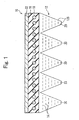
- Fig. 1 is a cross-sectional view of a V-ribbed belt 10.
- the V-ribbed belt 10 (a friction transmission belt) includes a bottom rubber layer 12, an adhesive rubber layer 16, and a fabric 22.
- the bottom rubber layer 12 and the fabric 22 are provided on the surfaces of the V-ribbed belt 10.
- the adhesive rubber layer 16 is layered on the bottom rubber layer 12, and the surface of the adhesive rubber layer 16 is covered with the fabric 22.
- a plurality of V-ribs 20 are formed on the bottom rubber layer 12.
- the V-ribs 20 are extending along the longitudinal direction of the V-ribbed belt 10, and are arranged along the width direction of the V-ribbed belt 10.
- the surfaces of the V-ribs 20, that is, the surfaces 12S of the bottom rubber layer 12, are friction surfaces that engage a pulley (not shown). Many short fibers 14 are included in the bottom rubber layer 12.
- the short fibers 14 are oriented roughly parallel to the width direction of the V-ribbed belt 10. A part of the short fibers 14 protrude from the side surfaces of the V-ribs 20, or from the friction surface 12S of the bottom rubber layer 12. A cord 18 (a tension member) is embedded near the center of the adhesive rubber layer 16.
- Table 1 represents formulations of the rubber layer materials used for forming the bottom rubber layer 12 in the working and comparative examples of the first embodiment.
- Table 1 FORMULATIONS OF THE RUBBER LAYER MATERIALS (*) RUBBER MATERIAL REINFORCEMENT (CARBON BLACK) GRAPHITE SHORT FIBER EPDM HAF FEF SRF NYLON 66 COTTON WORKING EXAMPLE 1 100 0 60 0 15 10 10 WORKING EXAMPLE 2 100 50 0 0 15 15 10 COMPARATIVE EXAMPLE 1 100 60 0 0 0 25 0 COMPARATIVE EXAMPLE 2 100 0 0 50 15 15 10 (*) WALL UNIT IS WEIGHT PART
- the rubber layer materials include 100 weight parts of EPDM (Ethylene Propylene Terpolymer) as a main component. Further, every working and comparative example includes a carbon black as a reinforcement to improve the rubber strength and modulus characteristics of the rubber.
- EPDM Ethylene Propylene Terpolymer
- working example 1 60 weight parts of an FEF (the code N500 equivalent of ASTM D1765-01 with an average nitrogen adsorption surface area of 40 to 49 (m 2 /g)), in working example 2 and comparative example 1, 50 or 60 weight parts of an HAF (the code N300 equivalent of ASTM D1765-01 with an average nitrogen adsorption surface area of 70 to 99 (m 2 /g)), and in comparative example 2, 50 weight parts of an SRF (the code N700 equivalent of ASTM D1765-01 with an average nitrogen adsorption surface area of 21 to 32 (m 2 /g)), are used.
- the rubber layer materials of working examples 1, 2 and of comparative example 2 include 15 weight parts of graphite to prevent stick-slip of the V-ribbed belt 10 under steady-state operation.
- the short fibers 14 (see Fig. 1 ) of cotton or nylon 66 are included.
- the water absorbent cotton assists with water removed from the friction surface.
- common components such as sulfur as a vulcanizing agent and anti-aging agent, are added.
- the V-ribbed belts 10 of the working and comparative examples are manufactured from the rubber layer materials represented in Fig. 1 . That is, the material of the fabric 22, the material sheet for the adhesive rubber layer 16, the cord 18, and the above explained rubber layer material are wound on a cylindrical drum (not shown), which is heated and pressurized at a predetermined temperature and pressure. At the time of heating and pressurization, two material sheets of the adhesive rubber layer 16, into which the cord 18 is embedded, are wound onto the cylindrical drum so that the cord 18 is arranged inside of the adhesive rubber layer 16 (see Fig.1 ).
- V-ribbed belt 10 including the bottom rubber layer 12, the adhesive rubber layer 16, the cord 18, and the fabric 22 (see Fig.1 ) is manufactured.
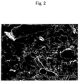
- Fig. 2 is a magnified image of the friction surface 12S of the bottom rubber layer 12, that is, the friction surface of the V-ribbed belt 10 manufactured from the rubber layer material of working example 1 and subjected to use for a predetermined time.
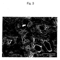
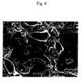
- Figs. 3 to 5 are magnified images of working example 2, and comparative examples 1 and 2, respectively, which correspond to Fig. 2 .
- the V-ribbed belt 10 was trained over a drive pulley and a driven pulley, both of which having a diameter of 120 mm, and a tensioner pulley with a diameter of 45 mm, the V-ribbed belt 10 was run for 24 hours at a temperature of 85 degrees Celsius, and at a rotating speed of 4900 rpm of the driven pulley.
- the magnified images of the friction surfaces 12S of the V-ribbed belt 10 in Figs. 2 to 5 were photographed by a SEM (a scanning type electron microscope) at 300X magnification.
- the short fibers 14 Prior to use, in each of the bottom rubber layers 12 of the working and comparative examples, the short fibers 14 (see Fig. 1 ) protrude from the friction surface 12S of the bottom rubber layer 12, that is, from the friction surface. Therefore, the friction surface is not smooth, and in the presence of water on its surface, the water runs off and does not adhere to it, so the water is drained and no abnormal noise is emitted.
- the short fibers 14 which initially protruded from the friction surface of the V-ribbed belt 10 had been worn down, thus decreasing unevenness of the friction surface in varying degrees among working and comparative examples. The resulting condition of the friction surface was maintained in order of decreasing unevenness as follows: comparative example 2, working example 1, working example 2, and comparative example 1 (see Figs. 2 to 5 ).
- the V-ribbed belt 10 was trained over a drive pulley with a diameter of 130 mm, a tensioner pulley with a diameter of 55 mm, and a driven pulley with a diameter of 128 mm.
- the driven pulley was rotated at 1000 rpm.
- the test condition was adjusted so that the load torque applied to the driven pulley was 10.0 Nm.
- water was poured onto the drive pulley at a rate of 300ml per minute, and the resulting existence or absence of slippage of the V-ribbed belt 10 was examined.
- Fig. 6 represents the result of the first water pouring slippage test of the V-ribbed belt 10 of working example 1 that has been used for 24 hours under the condition of the predetermined time usage explained above.
- Figs. 7 and 8 represent the test results for working example 2 and comparative example 1, respectively, which correspond to those of Fig. 6 .
- the bold line represents the voltage (sound voltage) corresponding to the magnitude of noise caused by the V-ribbed belt and detected by a microphone (not shown), and the thin line represents the number of revolutions of the driven pulley, respectively.
- the horizontal axes represent time.
- the second water pouring slippage test is carried out under the same condition as the first water pouring slippage test, except for the provision of a 5mm shim between the driven pulley and a different level on a different part of the driven pulley axis, thus slightly angling the V-ribbed belt 10 against the drive pulley.
- the condition of the second water pouring slippage test is more severe than that of the first water pouring slippage test.
- the second water pouring slippage test is carried out for the V-ribbed belt 10 of working examples 1 and 2 and comparative examples 1 and 2 after they have been in use for 24 hours under the previously explained conditions of the predetermined time usage, similar to the first water pouring slippage test.
- the number of revolutions of the driven pulley is approximately constant, and the V-ribbed belt 10 of working example 1 does not slip (see Fig. 9 ).
- the V-ribbed belt 10 slips shortly after starting the test due to the water poured onto the drive pulley, causing an abnormal high frequency noise to occur later on, when the V-ribbed belt 10 resumes running normally (see Figs. 10 to 12 ). Therefore, the V-ribbed belt 10 of working example 2 that represented good results in the first water pouring slippage test, did not represent a good result in the second water pouring slippage test, whose conditions were more severe than those of the first water pouring slippage test.
- the V-ribbed belt 10 of working examples is capable of preventing an abnormal noise due to slippage thereof.
- the FEF with the average nitrogen adsorption surface area between 40 and 49 (m 2 /g) is especially suitable as a carbon black to form the uneven surfaces for water drainage purpose, because working example 1 produced better results than those of working example 2.
- HAF carbon black with average nitrogen adsorption surface area between approximately 70 and 99 (m 2 /g) is used, the slippage of the V-ribbed belt 10 and generation of an abnormal noise can be prevented under mild usage conditions (see Figs. 7 and 10 ). Therefore, by using the surface unevenness can be maintained for water drainage purposes even when the short fibers 14 protruding from the friction surface 12S are worn down.
- slippage of the V-ribbed belt 10 and generation of an abnormal noise can be prevented even in the presence of water accumulated on the friction surface 12S of the V-ribbed belt 10, by modifying the reinforcement included in the bottom rubber layer 12 of the V-ribbed belt 10.
- the rubber layer material to form the bottom rubber layer 12 includes a diatomaceous earth, differing from the first embodiment.
- the V-ribbed belt 10 was manufactured in the same method as one in the first embodiment, excluding the formulation of the rubber layer material.
- Table 2 represents formulations of the rubber layer materials of the working and comparative examples of the second embodiment.
- Table 2 FORMULATIONS OF THE RUBBER LAYER MATERIALS (*) RUBBER MATERIAL REINFORCEMENT (CARBON BLACK) DIATOMACEOUS EARTH ZEOLITE SHORT FIBER COEFFICIENT OF STATIC FRICTION EPDM HAF FEF SRF PARTICLE SIZE 9 ⁇ m PARTICLE SIZE 23.4 ⁇ m PARTICLE SIZE 43.6 ⁇ m PARTICLE SIZE 0.2mm PARTICLE SIZE 1.25 ⁇ m NYLON 66 PRE-USE POST-USE WORKING EXAMPLE 3 100 0 60 0 10 0 0 0 0 25 0.679 0.637 WORKING EXAMPLE 4 100 0 60 0 15 0 0 0 0 25 0.640 0.795 WORKING EXAMPLE 5 100 0 60 0 20 0 0 0 0 25 0.545 0.713 COMPARATIVE
- the first water pouring slippage test explained above is carried out for each of the V-ribbed belts 10 (see Fig. 1 ) that were manufactured from the rubber layer materials of the working examples 3 to 5 and comparative examples 3 to 5.
- the test was carried out not only for the V-ribbed belts 10 which were subjected to use for a predetermined time under the same condition as the one in the first embodiment (post-use), but also for the V-ribbed belts 10 which were not used (pre-use).
- the V-ribbed belts 10 of the working examples 3 and 4 produced especially good results where there was neither slippage, nor abnormal noise. Also, the V-ribbed belts 10 of the working example 5 produced good results. That is, although a slight slippage and an abnormal noise were produced in the post-used V-ribbed belts 10 of the working example 5, the V-ribbed belts 10 of the working example 5 that was in the pre-use state produced results as good as the working examples 3 and 4.
- the V-ribbed belts 10 of the comparative examples 3 and 4 slip, due to the less diatomaceous earth and the lack of water-absorbency of the bottom rubber layer 12.
- the V-ribbed belt 10 also slips, because the coefficient of friction of the friction surface 12S (see Table 2) becomes lower than required, from excessive addition of diatomaceous earth. It is considered that as a result, larger abnormal noises were generated in the comparative examples 3 to 5 than in the working examples 3 to 5.
- diatomaceous earth with an average particle size smaller than or equal to 20 ⁇ m (for example, as small as about 9 ⁇ m), is suitable for addition to the rubber layer material of the V-ribbed belt 10.
- the reasons for this are as follows. First, in the V-ribbed belt 10 which includes the diatomaceous earth of a smaller particle size, the amount of diatomaceous earth exposed on the friction surface 12S of the bottom rubber layer 12 (see Fig. 1 ) is greater than the V-ribbed belt 10 which includes the diatomaceous earth of larger particle size but same weight content. Secondly, smaller diatomaceous earth has greater surface area per unit weight content, so it has superior water absorbency than larger diatomaceous earth.
- comparative examples 8 and 9 are explained. These comparative examples corresponded to comparative example 1 plus diatomaceous earth, and the HAF carbon black was used in comparative examples 8 and 9. In these comparative examples 8 and 9, as well as the other comparative examples, generation of a slippage and an abnormal noise were clearly found, regardless of the pre- or post-use state of the V-ribbed belts 10.
- comparative examples 10 to 12 are explained.
- the amounts of added carbon black were less than in the other working and comparative examples, or no carbon black was added.
- the formulation of the comparative example 12 which includes no carbon black By using the formulation of the comparative example 12 which includes no carbon black, a uniform rubber layer material was not produced, and the V-ribbed belt 10 could not manufactured.
- generation of a slippage and an abnormal noise were also clearly found, regardless of the pre- or post-use state of the V-ribbed belts 10.
- comparative examples 13 and 14 are explained.
- zeolite was added to the rubber layer materials, unlike the other working examples. 15 weight parts of each of zeolite either with an average particle size of 0.2mm or of 1.25 ⁇ m, was used (see Table 2). The only difference between the formulations of comparative examples 13 and 14 and that of comparative example 3, is the zeolite.
- generation of a slippage and an abnormal noise were also clearly found, regardless of the pre- or post-use status of the V-ribbed belts 10.
- generation of a slippage and an abnormal noise of the V-rilabed belt 10 in the presence of water accumulated on the friction surface can be reliably prevented by adding diatomaceous earth, an inorganic porous material, to the rubber layer material.
- each member composing the V-ribbed belt 10, such as the bottom rubber layer 12 are not limited to those in either of the two embodiments.
- the carbon black with the average nitrogen adsorption surface area of the predetermined range can prevent belt slippage and resulting abnormal noises as explained above
- XCF, GPF and so on may also be used as a reinforcement of the bottom rubber layer 12, in addition to the FEF and HAF used in the embodiments.
- silica may be used instead of, or in addition to a carbon black, as a reinforcement.
- Types of diatomaceous earths different from those of the embodiments may be used, such as ones having different average particle sizes.
- the bottom rubber layer 12 may be made from a CR rubber, a hydrogenated nitrile rubber, a styrene-butadiene rubber, a natural rubber and so on. Note that a peroxide may be used instead of a sulfur for a crosslinking reaction of the EPDM and so on. Further, the rubber materials of the bottom rubber layer 12 of the present embodiments may be applied to a friction transmission belt other than the V-ribbed belt 10, such as a flat belt or a V-belt.
- a friction transmission belt which can prevent generation of an abnormal noise even when water has accumulated thereon, can be supplied.
Landscapes
- Engineering & Computer Science (AREA)
- General Engineering & Computer Science (AREA)
- Mechanical Engineering (AREA)
- Chemical & Material Sciences (AREA)
- Health & Medical Sciences (AREA)
- Chemical Kinetics & Catalysis (AREA)
- Medicinal Chemistry (AREA)
- Polymers & Plastics (AREA)
- Organic Chemistry (AREA)
- Compositions Of Macromolecular Compounds (AREA)
- Manufacture Of Macromolecular Shaped Articles (AREA)
- Laminated Bodies (AREA)
Abstract
Description
- The present invention relates to a belt used for an automotive engine, general industrial power transmission machinery, and so on, especially to a friction transmission belt which can be prevented from producing an abnormal noise.
- In automobiles, general industrial power transmission machinery, and so on, friction transmission belts such as V-belts, V-ribbed belts, and flat belts, are widely used for power transmission.
- It is not uncommon to have an abnormal noise emanate from a friction transmission belt in normal use. Such an abnormal noise may even be generated when the friction transmission belt and pulleys operate without malfunction. For example, in a case where water accumulates on a smooth surface of a friction transmission belt which has been in use for a long period of time, the trend of abnormal noise generation is remarkable. This is because when the friction transmission belt slips due to a water film generated on the friction contact surfaces of a pulley and the friction transmission belt, later on, a water film disappears and then the pulley re-starts rotating, an abnormal noise is easily produced at the time when the water is drained.
- A user of a friction transmission belt often regards the occurrence of the abnormal noise to be problematic; therefore, for example in an automobile in which a friction transmission belt is in use, countermeasures are undertaken to prevent water from accumulating on the friction transmission belt because it is a primary cause of an abnormal noise coming from the transmission belt. However, it is difficult to completely prevent an abnormal noise caused by water, therefore, developing a friction transmission belt that does not make abnormal noises, even in the presence of water, is desired not only by a user of a friction transmission belt, but by auto manufacturers as well.
- The objective of the present invention is to provide a friction transmission belt which can prevent the generation of an abnormal noise in spite of the presence of water is thereon.
- In the friction transmission belt according to the present invention, a rubber layer having a friction surface is included. The rubber layer includes a reinforcement, and the friction surface is uneven in order to drain water so that slippage of the friction transmission belt caused by water accumulating on the friction surface is prevented.
- The reinforcement may include a carbon black. In this case, the average nitrogen adsorption surface area (ASTM D1765-01) of the carbon black is preferably between 33 and 99 (m2/g), and ideally between 40 and 49 (m2/g).
- Further, the rubber layer preferably includes short fibers. The rubber layer may be formed from a rubber comprising an EPDM (Ethylene Propylene Terpolymer).
- The friction transmission belt may further include an adhesive rubber layer bonded to the rubber layer, with a tension member embedded in the adhesive rubber layer.
- A rubber layer material, according to the present invention, forms a rubber layer of a friction transmission belt. The rubber layer has a friction surface. The rubber layer material includes a reinforcement. The rubber layer material creates an uneven friction surface in order to drain water so that slippage of the friction transmission belt caused by water accumulating on the friction surface is prevented.
- The present invention will be better understood from the description of the preferred embodiments of the invention set forth below, together with the accompanying drawings in which:
-
Fig. 1 is a sectional view of a V-ribbed belt of the first embodiment; -
Fig. 2 is a magnified image of a friction surface of a bottom rubber layer of a V-ribbed belt that has been in use for a predetermined time and was manufactured from a rubber layer material of working example 1; -
Fig. 3 is a magnified image of a friction surface of a bottom rubber layer of a V-ribbed belt that has been in use for a predetermined time and was manufactured from a rubber layer material of working example 2; -
Fig. 4 is a magnified image of a friction surface of a bottom rubber layer of a V-ribbed belt that has been in use for a predetermined time and was manufactured from a rubber layer material of comparative example 1; -
Fig. 5 is a magnified image of a friction surface of a bottom rubber layer of a V-ribbed belt that has been in use for a predetermined time and was manufactured from a rubber layer material of comparative example 2; -
Fig. 6 is a view representing the results of the first water pouring slippage test of a previously used V-ribbed belt of working example 1; -
Fig. 7 is a view representing the results of the first water pouring slippage test of a previously used V-ribbed belt of working example 2; -
Fig. 8 is a view representing the results of the first water pouring slippage test of a previously used V-ribbed belt of comparative example 1; -
Fig. 9 is a view representing the results of the second water pouring slippage test of a previously used V-ribbed belt of working example 1; -
Fig. 10 is a view representing the results of the second water pouring slippage test of a previously used V-ribbed belt of working example 2; -
Fig. 11 is a view representing the results of the second water pouring slippage test of a previously used V-ribbed belt of comparative example 1; and -
Fig. 12 is a view representing the results of the second water pouring slippage test of a previously used V-ribbed belt of comparative example 2. - Hereinafter, the first embodiment of the present invention is explained with reference to the attached figures.
Fig. 1 is a cross-sectional view of a V-ribbedbelt 10. - The V-ribbed belt 10 (a friction transmission belt) includes a
bottom rubber layer 12, anadhesive rubber layer 16, and afabric 22. Thebottom rubber layer 12 and thefabric 22 are provided on the surfaces of the V-ribbedbelt 10. Theadhesive rubber layer 16 is layered on thebottom rubber layer 12, and the surface of theadhesive rubber layer 16 is covered with thefabric 22. A plurality of V-ribs 20 are formed on thebottom rubber layer 12. The V-ribs 20 are extending along the longitudinal direction of the V-ribbedbelt 10, and are arranged along the width direction of the V-ribbedbelt 10. The surfaces of the V-ribs 20, that is, thesurfaces 12S of thebottom rubber layer 12, are friction surfaces that engage a pulley (not shown). Manyshort fibers 14 are included in thebottom rubber layer 12. Theshort fibers 14 are oriented roughly parallel to the width direction of the V-ribbedbelt 10. A part of theshort fibers 14 protrude from the side surfaces of the V-ribs 20, or from thefriction surface 12S of thebottom rubber layer 12. A cord 18 (a tension member) is embedded near the center of theadhesive rubber layer 16. - Next, the formulations of the
bottom rubber layer 12 are explained. Table 1 represents formulations of the rubber layer materials used for forming thebottom rubber layer 12 in the working and comparative examples of the first embodiment.Table 1 FORMULATIONS OF THE RUBBER LAYER MATERIALS (*) RUBBER MATERIAL REINFORCEMENT
(CARBON BLACK)GRAPHITE SHORT FIBER EPDM HAF FEF SRF NYLON 66 COTTON WORKING EXAMPLE 1 100 0 60 0 15 10 10 WORKING EXAMPLE 2 100 50 0 0 15 15 10 COMPARATIVE EXAMPLE 1 100 60 0 0 0 25 0 COMPARATIVE EXAMPLE 2 100 0 0 50 15 15 10 (*) WALL UNIT IS WEIGHT PART - In all working and comparative examples, the rubber layer materials include 100 weight parts of EPDM (Ethylene Propylene Terpolymer) as a main component. Further, every working and comparative example includes a carbon black as a reinforcement to improve the rubber strength and modulus characteristics of the rubber. In working example 1, 60 weight parts of an FEF (the code N500 equivalent of ASTM D1765-01 with an average nitrogen adsorption surface area of 40 to 49 (m2/g)), in working example 2 and comparative example 1, 50 or 60 weight parts of an HAF (the code N300 equivalent of ASTM D1765-01 with an average nitrogen adsorption surface area of 70 to 99 (m2/g)), and in comparative example 2, 50 weight parts of an SRF (the code N700 equivalent of ASTM D1765-01 with an average nitrogen adsorption surface area of 21 to 32 (m2/g)), are used. The rubber layer materials of working examples 1, 2 and of comparative example 2 include 15 weight parts of graphite to prevent stick-slip of the V-ribbed
belt 10 under steady-state operation. - In the rubber layer materials of each working and comparative example, the short fibers 14 (see
Fig. 1 ) of cotton or nylon 66 are included. The water absorbent cotton assists with water removed from the friction surface. Further, in these rubber layer materials, common components such as sulfur as a vulcanizing agent and anti-aging agent, are added. - The V-ribbed
belts 10 of the working and comparative examples are manufactured from the rubber layer materials represented inFig. 1 . That is, the material of thefabric 22, the material sheet for theadhesive rubber layer 16, thecord 18, and the above explained rubber layer material are wound on a cylindrical drum (not shown), which is heated and pressurized at a predetermined temperature and pressure. At the time of heating and pressurization, two material sheets of theadhesive rubber layer 16, into which thecord 18 is embedded, are wound onto the cylindrical drum so that thecord 18 is arranged inside of the adhesive rubber layer 16 (seeFig.1 ). - After heating and pressurizing the cylindrical drum, a vulcanized sleeve is cut to a predetermined width, and V-
ribs 20 can be formed thereon by cutting a part from the bottom rubber layer. Thus the V-ribbedbelt 10 including thebottom rubber layer 12, theadhesive rubber layer 16, thecord 18, and the fabric 22 (seeFig.1 ) is manufactured. - Next, the surface shape of the
bottom rubber layer 12 that is formed from the rubber layer materials of the working and comparative examples is explained.Fig. 2 is a magnified image of thefriction surface 12S of thebottom rubber layer 12, that is, the friction surface of the V-ribbedbelt 10 manufactured from the rubber layer material of working example 1 and subjected to use for a predetermined time.Figs. 3 to 5 are magnified images of working example 2, and comparative examples 1 and 2, respectively, which correspond toFig. 2 . - Note that the conditions of the above mentioned predetermined time of usage are as follows. The V-ribbed
belt 10 was trained over a drive pulley and a driven pulley, both of which having a diameter of 120 mm, and a tensioner pulley with a diameter of 45 mm, the V-ribbedbelt 10 was run for 24 hours at a temperature of 85 degrees Celsius, and at a rotating speed of 4900 rpm of the driven pulley. The magnified images of the friction surfaces 12S of the V-ribbedbelt 10 inFigs. 2 to 5 were photographed by a SEM (a scanning type electron microscope) at 300X magnification. - Prior to use, in each of the bottom rubber layers 12 of the working and comparative examples, the short fibers 14 (see
Fig. 1 ) protrude from thefriction surface 12S of thebottom rubber layer 12, that is, from the friction surface. Therefore, the friction surface is not smooth, and in the presence of water on its surface, the water runs off and does not adhere to it, so the water is drained and no abnormal noise is emitted. However, following the predetermined time of usage, theshort fibers 14 which initially protruded from the friction surface of the V-ribbedbelt 10 had been worn down, thus decreasing unevenness of the friction surface in varying degrees among working and comparative examples. The resulting condition of the friction surface was maintained in order of decreasing unevenness as follows: comparative example 2, working example 1, working example 2, and comparative example 1 (seeFigs. 2 to 5 ). - Next, the results of the first water pouring slippage test of the V-ribbed
belt 10 for working examples and comparative examples are explained. - In the first water pouring slippage test, the V-ribbed
belt 10 was trained over a drive pulley with a diameter of 130 mm, a tensioner pulley with a diameter of 55 mm, and a driven pulley with a diameter of 128 mm. The driven pulley was rotated at 1000 rpm. At the time, the test condition was adjusted so that the load torque applied to the driven pulley was 10.0 Nm. 30 seconds into the start of the test, water was poured onto the drive pulley at a rate of 300ml per minute, and the resulting existence or absence of slippage of the V-ribbedbelt 10 was examined. -
Fig. 6 represents the result of the first water pouring slippage test of the V-ribbedbelt 10 of working example 1 that has been used for 24 hours under the condition of the predetermined time usage explained above.Figs. 7 and8 represent the test results for working example 2 and comparative example 1, respectively, which correspond to those ofFig. 6 . - In
Figs. 6 to 8 , and the following figures mentioned below, the bold line represents the voltage (sound voltage) corresponding to the magnitude of noise caused by the V-ribbed belt and detected by a microphone (not shown), and the thin line represents the number of revolutions of the driven pulley, respectively. The horizontal axes represent time. - In a comparison between the V-ribbed
belt 10 of working examples 1 and 2 following usage over the predetermined amount of time, the number of revolutions of the driven pulley is approximately constant (seeFigs. 6 and7 ). On the other hand, comparative example 1 experienced significant V-ribbedbelt 10 slippage shortly after the start of the test and water was poured onto the drive pulley, and a large decrease in the number of revolutions of the driven pulley. Afterwards, the V-ribbedbelt 10 resumed running normally, and an abnormal noise was produced when the number of revolution increased (seeFig. 8 ). - Note that the sound voltage has been also varied in the results of the first water pouring slippage test for working examples 1 and 2 (see
Figs. 6 and7 ), although the magnitude of the variations of the sound voltage was smaller than those of comparative example 1 (seeFig. 8 ). However, the abnormal noise only occurs in comparative example 1, as explained below. - In comparative example 1, a film of water forms on the contact surface of the driven pulley and the V-ribbed
belt 10 from the water poured onto the drive pulley, thus causing the V-ribbedbelt 10 to slip and the pulley to idle. Following the disappearance of the water film from the surface of the V-ribbedbelt 10, it suddenly resumes rotating, but causes a high frequency abnormal noise (seeFig. 8 ) . On the other hand, in regard to working examples 1 and 2 (seeFigs. 6 and7 ) the slippage of the V-ribbedbelt 10 is prevented, as indicated by the number of revolutions of the driven pulley, and the high frequency abnormal noise generated in the test of comparative example 1 is avoided. - Next, the results of the second water pouring slippage test of the V-ribbed
belt 10 for working examples and comparative examples are explained. - The second water pouring slippage test is carried out under the same condition as the first water pouring slippage test, except for the provision of a 5mm shim between the driven pulley and a different level on a different part of the driven pulley axis, thus slightly angling the V-ribbed
belt 10 against the drive pulley. As this configuration suggests, the condition of the second water pouring slippage test is more severe than that of the first water pouring slippage test. Note that the second water pouring slippage test is carried out for the V-ribbedbelt 10 of working examples 1 and 2 and comparative examples 1 and 2 after they have been in use for 24 hours under the previously explained conditions of the predetermined time usage, similar to the first water pouring slippage test. - In the second water pouring slippage test, the number of revolutions of the driven pulley is approximately constant, and the V-ribbed
belt 10 of working example 1 does not slip (seeFig. 9 ). On the other hand, with respect to working example 2 and comparative examples 1 and 2, the V-ribbedbelt 10 slips shortly after starting the test due to the water poured onto the drive pulley, causing an abnormal high frequency noise to occur later on, when the V-ribbedbelt 10 resumes running normally (seeFigs. 10 to 12 ). Therefore, the V-ribbedbelt 10 of working example 2 that represented good results in the first water pouring slippage test, did not represent a good result in the second water pouring slippage test, whose conditions were more severe than those of the first water pouring slippage test. - These test results validate the following facts. In comparative example 1, the film of water forms at the boundary surface between the pulley contact surface of the used V-ribbed
belt 10, that is, thefriction surface 12S (seeFigs. 1 and4 ), and the surface of the pulley, thus causing the V-ribbedbelt 10 to slip. Afterwards, the film of water is maintained for a relatively long period of time because of the relativelysmooth friction surface 12S, which disrupts the normal operation of the V-ribbedbelt 10. In comparative example 2, although thefriction surface 12S (seeFig. 5 ) is uneven, the V-ribbedbelt 10 slips and generates abnormal noise. This is because the wear of thefriction surface 12S is heavy and uneven wear is generated on thefriction surface 12S. - Contrary to these comparative examples, in working examples 1 and 2 where the friction surfaces 12S on the bottom rubber layer 12 (see
Figs. 2 and3 ) having suitable unevenness are properly provided, water on thefriction surface 12S is promptly removed, so that the V-ribbedbelt 10 has excellent anti-slippage performance. As a result, the V-ribbedbelt 10 of working examples is capable of preventing an abnormal noise due to slippage thereof. - As explained above, using an FEF with an average nitrogen adsorption surface area (ASTM D1765-01) between approximately 40 and 49 (m2/g) as a reinforcement, and providing minute unevenness on the
friction surface 12S of thebottom rubber layer 12 for water drainage (working example 1), can effectively prevent the slippage of the V-ribbedbelt 10 and the generation of abnormal noise (seeFigs. 6 and9 ), even under severe usage conditions where the V-ribbedbelt 10 is trained over pulleys inclined towards one another. Further, because the previously used V-ribbedbelt 10 of working example 1 can prevent the slippage thereof, it is apparent that the surface unevenness for water drainage can be maintained by using the FEF, even when the short fibers 14 (seeFig. 1 ) that contribute to maintaining the surface unevenness, that is, theshort fibers 14 which protrude from thefriction surface 12S of thebottom rubber layer 12, are worn down. Note that the FEF with the average nitrogen adsorption surface area between 40 and 49 (m2/g) is especially suitable as a carbon black to form the uneven surfaces for water drainage purpose, because working example 1 produced better results than those of working example 2. - Further, when HAF carbon black with average nitrogen adsorption surface area between approximately 70 and 99 (m2/g) is used, the slippage of the V-ribbed
belt 10 and generation of an abnormal noise can be prevented under mild usage conditions (seeFigs. 7 and10 ). Therefore, by using the surface unevenness can be maintained for water drainage purposes even when theshort fibers 14 protruding from thefriction surface 12S are worn down. - As mentioned above, because the abnormal noise effect can be mitigated in the V-ribbed
belt 10 of working examples 1 and 2 after an extended period of use, it is clear that the usage of the carbon blacks including the FEF, and HAF with average nitrogen adsorption surface areas between 33 and 99 (m2/g), excluding the SRF, can prevent belt slippage and abnormal noises. - As explained in the first embodiment, slippage of the V-ribbed
belt 10 and generation of an abnormal noise can be prevented even in the presence of water accumulated on thefriction surface 12S of the V-ribbedbelt 10, by modifying the reinforcement included in thebottom rubber layer 12 of the V-ribbedbelt 10. - Next, the second embodiment is explained. In the second embodiment, the rubber layer material to form the bottom rubber layer 12 (see
Fig. 1 ) includes a diatomaceous earth, differing from the first embodiment. In the second embodiment, the V-ribbed belt 10 (seeFig. 1 ) was manufactured in the same method as one in the first embodiment, excluding the formulation of the rubber layer material. - Table 2 represents formulations of the rubber layer materials of the working and comparative examples of the second embodiment.
Table 2 FORMULATIONS OF THE RUBBER LAYER MATERIALS (*) RUBBER MATERIAL REINFORCEMENT
(CARBON BLACK)DIATOMACEOUS EARTH ZEOLITE SHORT FIBER COEFFICIENT OF STATIC FRICTION EPDM HAF FEF SRF PARTICLE SIZE 9µm PARTICLE SIZE 23.4µm PARTICLE SIZE 43.6µm PARTICLE SIZE 0.2mm PARTICLE SIZE 1.25µm NYLON 66 PRE-USE POST-USE WORKING EXAMPLE 3 100 0 60 0 10 0 0 0 0 25 0.679 0.637 WORKING EXAMPLE 4 100 0 60 0 15 0 0 0 0 25 0.640 0.795 WORKING EXAMPLE 5 100 0 60 0 20 0 0 0 0 25 0.545 0.713 COMPARATIVE EXAMPLE 3 100 0 60 0 0 0 0 0 0 25 1.031 0.910 COMPARATIVE EXAMPLE 4 100 0 0 0 5 0 0 0 0 25 0.775 0.732 COMPARATIVE EXAMPLE 5 100 0 60 0 40 0 0 0 0 25 0.586 0.595 COMPARATIVE EXAMPLE 6 100 0 60 0 0 15 0 0 0 25 0.613 0.469 COMPARATIVE EXAMPLE 7 100 0 60 0 0 0 15 0 0 25 0.578 0.588 COMPARATIVE EXAMPLE 8 100 60 0 0 15 0 0 0 0 25 0.559 0.687 COMPARATIVE EXAMPLE 9 100 60 0 0 40 0 0 0 0 25 0.600 0.779 COMPARATIVE EXAMPLE 10 100 0 30 0 30 0 0 0 0 25 0.555 0.508 COMPARATIVE EXAMPLE 11 100 30 0 0 30 0 0 0 0 25 0.630 0.628 COMPARATIVE EXAMPLE 12 100 0 0 0 60 0 0 0 0 25 - - COMPARATIVE EXAMPLE 13 100 0 60 0 0 0 0 15 0 25 0.813 0.671 COMPARATIVE EXAMPLE 14 100 0 60 0 0 0 0 0 15 25 0.717 0.781 (*) ALL UNIT IS WEIGHT PART - In working examples 3 to 5 and comparative examples 3 to 5, 0 to 40 weight parts of diatomaceous earth are used with 100 weight parts of EPDM as a rubber material, 60 weight parts of FEF carbon black, and 25 weight parts of nylon 66 (see
Fig. 2 ). In these working and comparative examples, diatomaceous earth having an average particle size of 9µm is used. - The first water pouring slippage test explained above is carried out for each of the V-ribbed belts 10 (see
Fig. 1 ) that were manufactured from the rubber layer materials of the working examples 3 to 5 and comparative examples 3 to 5. In all working and comparative examples of the present embodiment, the test was carried out not only for the V-ribbedbelts 10 which were subjected to use for a predetermined time under the same condition as the one in the first embodiment (post-use), but also for the V-ribbedbelts 10 which were not used (pre-use). - In the first water pouring slippage test, the V-ribbed
belts 10 of the working examples 3 and 4 produced especially good results where there was neither slippage, nor abnormal noise. Also, the V-ribbedbelts 10 of the working example 5 produced good results. That is, although a slight slippage and an abnormal noise were produced in the post-used V-ribbedbelts 10 of the working example 5, the V-ribbedbelts 10 of the working example 5 that was in the pre-use state produced results as good as the working examples 3 and 4. - Further, the results of these working examples 3 to 5 are superior to those of the working examples 1 and 2 of the first embodiment, in terms of the following points: In the working examples 1 and 2, when the water pouring test had been repeated many times, generation of a slippage or an abnormal noise was sometimes found. In the working examples 3 to 5 of the present embodiment, however, the test results were constantly good.
- On the contrary, in the comparative examples 3 to 5, the test results were not good. That is, except for the V-ribbed
belt 10 of the comparative example 4 in the pre-use state, where relatively less slippage and abnormal noise were found, slippage and abnormal noise were clearly found in all of the V-ribbedbelts 10 of the comparative examples 3 to 5, regardless of pre- or post-use state. - From these test results, it is clear that adding 10 to 20 weight parts of diatomaceous earth to the 100 weight parts of rubber material in the rubber layer material (adding 5 to 10 weight percent of diatomaceous earth in the whole rubber layer material), further improves the anti-slippage property of the V-ribbed
belt 10, and more reliably prevents the generation of an abnormal noise. It is considered that these effects are provided by the water-absorbent diatomaceous earth which efficiently removes the water which accumulates on thefriction surface 12S (seeFig. 1 ) of thebottom rubber layer 12. - On the contrary, the V-ribbed
belts 10 of the comparative examples 3 and 4 slip, due to the less diatomaceous earth and the lack of water-absorbency of thebottom rubber layer 12. In the comparative example 5, the V-ribbedbelt 10 also slips, because the coefficient of friction of thefriction surface 12S (see Table 2) becomes lower than required, from excessive addition of diatomaceous earth. It is considered that as a result, larger abnormal noises were generated in the comparative examples 3 to 5 than in the working examples 3 to 5. - Next, comparative examples 6 and 7 are explained. In these comparative examples, the average particle size of the diatomaceous earth differed from the 9µm of the working examples 3 to 5, and were instead 23.4µm and 43.6µm, respectively (see Table 2). In these comparative examples 6 and 7, generation of the slippage and abnormal noise were clearly found, regardless of the pre- or post-use state.
- Therefore, diatomaceous earth with an average particle size smaller than or equal to 20µm (for example, as small as about 9 µm), is suitable for addition to the rubber layer material of the V-ribbed
belt 10. The reasons for this are as follows. First, in the V-ribbedbelt 10 which includes the diatomaceous earth of a smaller particle size, the amount of diatomaceous earth exposed on thefriction surface 12S of the bottom rubber layer 12 (seeFig. 1 ) is greater than the V-ribbedbelt 10 which includes the diatomaceous earth of larger particle size but same weight content. Secondly, smaller diatomaceous earth has greater surface area per unit weight content, so it has superior water absorbency than larger diatomaceous earth. - Next, comparative examples 8 and 9 are explained. These comparative examples corresponded to comparative example 1 plus diatomaceous earth, and the HAF carbon black was used in comparative examples 8 and 9. In these comparative examples 8 and 9, as well as the other comparative examples, generation of a slippage and an abnormal noise were clearly found, regardless of the pre- or post-use state of the V-ribbed
belts 10. - These test results in the present embodiment also demonstrate that the FEF is more suitable than the HAF as a carbon black for addition to the rubber layer material.
- Next, comparative examples 10 to 12 are explained. In these comparative examples, the amounts of added carbon black were less than in the other working and comparative examples, or no carbon black was added. By using the formulation of the comparative example 12 which includes no carbon black, a uniform rubber layer material was not produced, and the V-ribbed
belt 10 could not manufactured. In the comparative examples 10 and 11, generation of a slippage and an abnormal noise were also clearly found, regardless of the pre- or post-use state of the V-ribbedbelts 10. - Therefore, it is confirmed that when the additional amount of carbon black such as the FEF and HAF is reduced to about half of that in the above explained working and comparative examples, or reduced to nothing, good results are not obtained even when diatomaceous earth in an amount corresponding to the reduced amount of carbon black is added.
- Next, comparative examples 13 and 14 are explained. In these comparative examples, zeolite was added to the rubber layer materials, unlike the other working examples. 15 weight parts of each of zeolite either with an average particle size of 0.2mm or of 1.25µm, was used (see Table 2). The only difference between the formulations of comparative examples 13 and 14 and that of comparative example 3, is the zeolite. In comparative examples 13 and 14, generation of a slippage and an abnormal noise were also clearly found, regardless of the pre- or post-use status of the V-ribbed
belts 10. - As a result, in cases where zeolite is used instead of diatomaceous earth, no advantage is obtained. This may be because that zeolite has less water-absorbency than diatomaceous earth does, or due to the difference in the properties of the friction surfaces 12S of these examples and the others, such as unevenness.
- As explained in the present embodiment, generation of a slippage and an abnormal noise of the V-
rilabed belt 10 in the presence of water accumulated on the friction surface, can be reliably prevented by adding diatomaceous earth, an inorganic porous material, to the rubber layer material. - The materials of each member composing the V-ribbed
belt 10, such as thebottom rubber layer 12, are not limited to those in either of the two embodiments. For example, because the carbon black with the average nitrogen adsorption surface area of the predetermined range can prevent belt slippage and resulting abnormal noises as explained above, XCF, GPF and so on may also be used as a reinforcement of thebottom rubber layer 12, in addition to the FEF and HAF used in the embodiments. - Although no graphite was used in the second embodiment (the working examples 3 to 5 and comparative examples 3 to 12), a suitable amount the graphite may be used to prevent the coefficient of friction of the
friction surface 12S (seeFig. 1 ) from dropping below the required level. - Further, silica may be used instead of, or in addition to a carbon black, as a reinforcement.
- Types of diatomaceous earths different from those of the embodiments may be used, such as ones having different average particle sizes.
- Although there is an advantage to using a rubber made from the EPDM because of its generally superior anti-heat and anti-wear performance characteristics, the
bottom rubber layer 12 may be made from a CR rubber, a hydrogenated nitrile rubber, a styrene-butadiene rubber, a natural rubber and so on. Note that a peroxide may be used instead of a sulfur for a crosslinking reaction of the EPDM and so on. Further, the rubber materials of thebottom rubber layer 12 of the present embodiments may be applied to a friction transmission belt other than the V-ribbedbelt 10, such as a flat belt or a V-belt. - According to the present invention, a friction transmission belt which can prevent generation of an abnormal noise even when water has accumulated thereon, can be supplied.
Claims (9)
- A friction transmission belt comprising a rubber layer having a friction surface,
said rubber layer comprising a carbon black whose average nitrogen adsorption surface area (ASTM D1765-01) being between 33 and 99 (m2/g), said friction surface being uneven to drain water so that slippage of said friction transmission belt caused by water accumulating on said friction surface is prevented. - A friction transmission belt according to claim 1, wherein the average nitrogen adsorption surface area (ASTM D1765-01) of said carbon black is between 40 and 49 (m2/g).
- A friction transmission belt according to claim 1, wherein said rubber layer further comprises short fibers.
- A friction transmission belt according to claim 1, wherein said rubber layer further comprises diatomaceous earth.
- A friction transmission belt according to claim 4, wherein said rubber layer comprises 10 to 20 weight parts of said diatomaceous earth per 100 weight parts of rubber material.
- A friction transmission belt according to claim 4, wherein the average particle size of said diatomaceous earth is smaller than or equal to 20µm.
- A friction transmission belt according to claim 1, wherein said rubber layer is formed by a rubber comprising an EPDM (Ethylene Propylene Terpolymer).
- A friction transmission belt according to claim 1, further comprising an adhesive rubber layer bonded to said rubber layer, and a tension member embedded in said adhesive rubber layer.
- A rubber layer material to form a rubber layer of a friction transmission belt, said rubber layer having a friction surface;
said rubber layer material comprising a carbon black whose average nitrogen adsorption surface area (ASTM D1765-01) being between 33 and 99 (m2/g), said rubber layer material causing said uneven friction surface to drain water so that slippage of said friction transmission belt caused by water which is accumulating on said friction surface is prevented.
Applications Claiming Priority (2)
| Application Number | Priority Date | Filing Date | Title |
|---|---|---|---|
| PCT/JP2007/053987 WO2008102459A1 (en) | 2007-02-23 | 2007-02-23 | Friction transmission belt |
| PCT/JP2008/053344 WO2008102911A1 (en) | 2007-02-23 | 2008-02-20 | Friction transmission belt |
Publications (3)
| Publication Number | Publication Date |
|---|---|
| EP2128485A1 true EP2128485A1 (en) | 2009-12-02 |
| EP2128485A4 EP2128485A4 (en) | 2011-05-04 |
| EP2128485B1 EP2128485B1 (en) | 2015-05-20 |
Family
ID=39709744
Family Applications (1)
| Application Number | Title | Priority Date | Filing Date |
|---|---|---|---|
| EP08720893.0A Not-in-force EP2128485B1 (en) | 2007-02-23 | 2008-02-20 | Friction transmission belt |
Country Status (10)
| Country | Link |
|---|---|
| US (1) | US20100323835A1 (en) |
| EP (1) | EP2128485B1 (en) |
| KR (1) | KR101111543B1 (en) |
| CN (1) | CN101583809B (en) |
| CA (1) | CA2679037C (en) |
| ES (1) | ES2542057T3 (en) |
| MX (1) | MX2009008966A (en) |
| MY (1) | MY148316A (en) |
| TW (1) | TWI440780B (en) |
| WO (2) | WO2008102459A1 (en) |
Families Citing this family (12)
| Publication number | Priority date | Publication date | Assignee | Title |
|---|---|---|---|---|
| TWI404874B (en) * | 2010-06-18 | 2013-08-11 | Sanwu Rubber Mfg Co Ltd | V-ribbed power transmission belt and method for manufacturing the same |
| CN103168184B (en) * | 2010-10-21 | 2015-08-05 | 阪东化学株式会社 | Friction belt for power transmission |
| DE102010043322A1 (en) * | 2010-11-03 | 2012-05-03 | Arntz Beteiligungs Gmbh & Co. Kg | Drive belt for transmitting a drive movement and method for producing a drive belt |
| US9879131B2 (en) | 2012-08-31 | 2018-01-30 | Soucy Techno Inc. | Rubber compositions and uses thereof |
| US9840611B2 (en) | 2013-10-18 | 2017-12-12 | Soucy Techno Inc. | Rubber compositions and uses thereof |
| WO2015089647A1 (en) | 2013-12-19 | 2015-06-25 | Soucy Techno Inc. | Rubber compositions and uses thereof |
| EP3988153B1 (en) | 2015-03-31 | 2024-04-24 | Fisher & Paykel Healthcare Limited | A user interface for supplying gases to an airway |
| CN121668497A (en) | 2016-08-11 | 2026-03-17 | 费雪派克医疗保健有限公司 | Collapsible catheter, patient interface, and headgear connector |
| CN110799770B (en) * | 2017-07-19 | 2020-09-01 | 阪东化学株式会社 | Transmission belt and method of making the same |
| CN109897287A (en) * | 2019-01-30 | 2019-06-18 | 盖茨优霓塔传动系统(苏州)有限公司 | Flat-toothed belt |
| US12123475B2 (en) * | 2020-01-16 | 2024-10-22 | Mitsuboshi Belting Ltd. | Core wire for drive belt, drive belt, and method for manufacturing core wire and drive belt |
| JP7293486B1 (en) | 2022-01-20 | 2023-06-19 | 三ツ星ベルト株式会社 | Rubber composition for power transmission belt and power transmission belt |
Family Cites Families (29)
| Publication number | Priority date | Publication date | Assignee | Title |
|---|---|---|---|---|
| JPS61156754U (en) * | 1985-03-20 | 1986-09-29 | ||
| JP3113027B2 (en) * | 1991-12-17 | 2000-11-27 | 株式会社椿本チエイン | Toothed belt and method of manufacturing the same |
| EP0686714B1 (en) * | 1994-06-06 | 2001-09-19 | Bando Chemical Industries, Limited | Method of producing short fibers |
| CN1082525C (en) * | 1994-08-08 | 2002-04-10 | 旭化成株式会社 | hydrogenated rubber composition |
| US5610217A (en) * | 1994-10-31 | 1997-03-11 | The Gates Corporation | Ethylene-alpha-olefin belting |
| JP3021362B2 (en) * | 1995-09-20 | 2000-03-15 | 三ツ星ベルト株式会社 | Conveyor toothed belt |
| CA2203617C (en) * | 1996-04-26 | 2000-08-08 | Hiroshi Jonen | Power transmission belt |
| US5886066A (en) * | 1997-07-17 | 1999-03-23 | Hoechst Celanese Corporation | Thermoplastic polymer composition exhibiting improved wear |
| JP2000039049A (en) * | 1998-07-23 | 2000-02-08 | Mitsuboshi Belting Ltd | V-ribbed belt |
| JP3069337B2 (en) * | 1998-12-08 | 2000-07-24 | バンドー化学株式会社 | Power transmission belt and elastomer composition |
| US6432013B1 (en) * | 1999-05-24 | 2002-08-13 | Bando Chemical Industries, Ltd. | Power transmission belt and method for fabricating the same |
| US6435997B1 (en) * | 1999-05-24 | 2002-08-20 | Bando Chemical Industries, Ltd. | Power transmission belt and method for fabricating the same |
| EP1149866A3 (en) * | 2000-04-27 | 2003-04-23 | JSR Corporation | Rubber mixtures based on crosslinked rubber particles and non-crosslinked rubbers |
| DE60139428D1 (en) * | 2000-06-07 | 2009-09-10 | Zeon Corp | Conjugated diene rubber gel, rubber compositions containing the same and processes for producing conjugated diene rubber |
| US6512039B1 (en) * | 2001-11-16 | 2003-01-28 | Lord Corporation | Adhesives for bonding peroxide-cured elastomers |
| CA2423498C (en) * | 2002-03-28 | 2006-08-01 | Mitsuboshi Belting Ltd. | Power transmission belt |
| US6824485B2 (en) * | 2002-07-09 | 2004-11-30 | The Gates Corporation | Power transmission belt |
| JP2004060779A (en) * | 2002-07-29 | 2004-02-26 | Mitsuboshi Belting Ltd | V-ribbed belt |
| JP4133595B2 (en) * | 2002-08-08 | 2008-08-13 | ゲイツ・ユニッタ・アジア株式会社 | Transmission belt |
| JP2004176904A (en) * | 2002-09-30 | 2004-06-24 | Mitsuboshi Belting Ltd | Power transmission belt |
| JP4772292B2 (en) * | 2003-05-30 | 2011-09-14 | 三ツ星ベルト株式会社 | Transmission belt |
| JP4856375B2 (en) * | 2004-12-28 | 2012-01-18 | 三ツ星ベルト株式会社 | V-ribbed belt |
| JP2007032753A (en) * | 2005-07-28 | 2007-02-08 | Mitsuboshi Belting Ltd | Transmission belt |
| JP4672603B2 (en) * | 2005-08-31 | 2011-04-20 | 三ツ星ベルト株式会社 | Friction transmission belt |
| US20090075770A1 (en) * | 2006-03-24 | 2009-03-19 | Bando Chemical Industries, Ltd. | Power transmission belt |
| US9506527B2 (en) * | 2006-04-07 | 2016-11-29 | Gates Corporation | Power transmission belt |
| US7524902B2 (en) * | 2006-05-30 | 2009-04-28 | Sabic Innovative Plastics Ip B.V. | Core-shell particle composition, method, and article |
| CN101535059B (en) * | 2006-11-13 | 2013-01-09 | 米其林集团总公司 | Elastomer compositions with carbon black |
| JP5358191B2 (en) | 2006-12-22 | 2013-12-04 | バンドー化学株式会社 | Rubber composition for transmission belt and transmission belt |
-
2007
- 2007-02-23 WO PCT/JP2007/053987 patent/WO2008102459A1/en not_active Ceased
-
2008
- 2008-02-20 MY MYPI20092728A patent/MY148316A/en unknown
- 2008-02-20 US US12/449,447 patent/US20100323835A1/en not_active Abandoned
- 2008-02-20 WO PCT/JP2008/053344 patent/WO2008102911A1/en not_active Ceased
- 2008-02-20 MX MX2009008966A patent/MX2009008966A/en unknown
- 2008-02-20 EP EP08720893.0A patent/EP2128485B1/en not_active Not-in-force
- 2008-02-20 CN CN2008800014505A patent/CN101583809B/en not_active Expired - Fee Related
- 2008-02-20 TW TW097105876A patent/TWI440780B/en not_active IP Right Cessation
- 2008-02-20 KR KR1020097013680A patent/KR101111543B1/en not_active Expired - Fee Related
- 2008-02-20 ES ES08720893.0T patent/ES2542057T3/en active Active
- 2008-02-20 CA CA2679037A patent/CA2679037C/en not_active Expired - Fee Related
Also Published As
| Publication number | Publication date |
|---|---|
| CA2679037C (en) | 2015-09-08 |
| EP2128485B1 (en) | 2015-05-20 |
| MX2009008966A (en) | 2009-08-31 |
| CN101583809A (en) | 2009-11-18 |
| KR101111543B1 (en) | 2012-02-27 |
| TW200835868A (en) | 2008-09-01 |
| CA2679037A1 (en) | 2008-08-28 |
| EP2128485A4 (en) | 2011-05-04 |
| US20100323835A1 (en) | 2010-12-23 |
| CN101583809B (en) | 2012-09-26 |
| KR20090100378A (en) | 2009-09-23 |
| MY148316A (en) | 2013-03-29 |
| WO2008102459A1 (en) | 2008-08-28 |
| ES2542057T3 (en) | 2015-07-30 |
| TWI440780B (en) | 2014-06-11 |
| WO2008102911A1 (en) | 2008-08-28 |
Similar Documents
| Publication | Publication Date | Title |
|---|---|---|
| EP2128485B1 (en) | Friction transmission belt | |
| EP1540204B1 (en) | Power transmission belt | |
| EP2128486B1 (en) | Power transmission belt | |
| EP3214338B1 (en) | Friction transmission belt and manufacturing method thereof | |
| JP4745789B2 (en) | V-ribbed belt and method for manufacturing V-ribbed belt | |
| CN109642640B (en) | V-ribbed belts and their uses | |
| US7887448B2 (en) | Power transmission belt | |
| JP5058886B2 (en) | Friction transmission belt | |
| JP2019194494A (en) | V-ribbed belt and application thereof | |
| JP5179464B2 (en) | Friction transmission belt | |
| JP4757041B2 (en) | V-ribbed belt | |
| JP4515959B2 (en) | Transmission flat belt | |
| JP3559278B1 (en) | Transmission belt | |
| AU2003253659B2 (en) | Power transmission belt | |
| EP3786479B1 (en) | V-ribbed belt and application thereof | |
| WO2018043355A1 (en) | V-ribbed belt and use thereof | |
| JP2005336295A (en) | Rubber composition and transmission belt | |
| JP2006077785A (en) | Power transmission belt | |
| JP2007298162A (en) | Friction transmission belt | |
| JP2006258114A (en) | Friction transmission belt | |
| JP2008157319A (en) | Friction transmission belt | |
| JP2006153234A (en) | Transmission belt | |
| JP2008069910A (en) | Transmission flat belt | |
| JP2005155908A (en) | V-ribbed belt | |
| JP2006282763A (en) | METHOD FOR PRODUCING BONDED BODY OF ETHYLENE-alpha-OLEFIN ELASTOMER COMPOSITION AND FIBER AND POWER TRANSMISSION BELT |
Legal Events
| Date | Code | Title | Description |
|---|---|---|---|
| PUAI | Public reference made under article 153(3) epc to a published international application that has entered the european phase |
Free format text: ORIGINAL CODE: 0009012 |
|
| 17P | Request for examination filed |
Effective date: 20090922 |
|
| AK | Designated contracting states |
Kind code of ref document: A1 Designated state(s): AT BE BG CH CY CZ DE DK EE ES FI FR GB GR HR HU IE IS IT LI LT LU LV MC MT NL NO PL PT RO SE SI SK TR |
|
| DAX | Request for extension of the european patent (deleted) | ||
| A4 | Supplementary search report drawn up and despatched |
Effective date: 20110405 |
|
| 17Q | First examination report despatched |
Effective date: 20120416 |
|
| GRAP | Despatch of communication of intention to grant a patent |
Free format text: ORIGINAL CODE: EPIDOSNIGR1 |
|
| INTG | Intention to grant announced |
Effective date: 20141203 |
|
| GRAS | Grant fee paid |
Free format text: ORIGINAL CODE: EPIDOSNIGR3 |
|
| GRAA | (expected) grant |
Free format text: ORIGINAL CODE: 0009210 |
|
| AK | Designated contracting states |
Kind code of ref document: B1 Designated state(s): AT BE BG CH CY CZ DE DK EE ES FI FR GB GR HR HU IE IS IT LI LT LU LV MC MT NL NO PL PT RO SE SI SK TR |
|
| REG | Reference to a national code |
Ref country code: GB Ref legal event code: FG4D |
|
| REG | Reference to a national code |
Ref country code: CH Ref legal event code: EP |
|
| REG | Reference to a national code |
Ref country code: AT Ref legal event code: REF Ref document number: 727902 Country of ref document: AT Kind code of ref document: T Effective date: 20150615 |
|
| REG | Reference to a national code |
Ref country code: IE Ref legal event code: FG4D |
|
| REG | Reference to a national code |
Ref country code: DE Ref legal event code: R096 Ref document number: 602008038219 Country of ref document: DE |
|
| REG | Reference to a national code |
Ref country code: ES Ref legal event code: FG2A Ref document number: 2542057 Country of ref document: ES Kind code of ref document: T3 Effective date: 20150730 |
|
| REG | Reference to a national code |
Ref country code: AT Ref legal event code: MK05 Ref document number: 727902 Country of ref document: AT Kind code of ref document: T Effective date: 20150520 |
|
| REG | Reference to a national code |
Ref country code: LT Ref legal event code: MG4D |
|
| REG | Reference to a national code |
Ref country code: NL Ref legal event code: MP Effective date: 20150520 |
|
| PG25 | Lapsed in a contracting state [announced via postgrant information from national office to epo] |
Ref country code: NO Free format text: LAPSE BECAUSE OF FAILURE TO SUBMIT A TRANSLATION OF THE DESCRIPTION OR TO PAY THE FEE WITHIN THE PRESCRIBED TIME-LIMIT Effective date: 20150820 Ref country code: HR Free format text: LAPSE BECAUSE OF FAILURE TO SUBMIT A TRANSLATION OF THE DESCRIPTION OR TO PAY THE FEE WITHIN THE PRESCRIBED TIME-LIMIT Effective date: 20150520 Ref country code: FI Free format text: LAPSE BECAUSE OF FAILURE TO SUBMIT A TRANSLATION OF THE DESCRIPTION OR TO PAY THE FEE WITHIN THE PRESCRIBED TIME-LIMIT Effective date: 20150520 Ref country code: LT Free format text: LAPSE BECAUSE OF FAILURE TO SUBMIT A TRANSLATION OF THE DESCRIPTION OR TO PAY THE FEE WITHIN THE PRESCRIBED TIME-LIMIT Effective date: 20150520 Ref country code: PT Free format text: LAPSE BECAUSE OF FAILURE TO SUBMIT A TRANSLATION OF THE DESCRIPTION OR TO PAY THE FEE WITHIN THE PRESCRIBED TIME-LIMIT Effective date: 20150921 |
|
| PG25 | Lapsed in a contracting state [announced via postgrant information from national office to epo] |
Ref country code: AT Free format text: LAPSE BECAUSE OF FAILURE TO SUBMIT A TRANSLATION OF THE DESCRIPTION OR TO PAY THE FEE WITHIN THE PRESCRIBED TIME-LIMIT Effective date: 20150520 Ref country code: LV Free format text: LAPSE BECAUSE OF FAILURE TO SUBMIT A TRANSLATION OF THE DESCRIPTION OR TO PAY THE FEE WITHIN THE PRESCRIBED TIME-LIMIT Effective date: 20150520 Ref country code: BG Free format text: LAPSE BECAUSE OF FAILURE TO SUBMIT A TRANSLATION OF THE DESCRIPTION OR TO PAY THE FEE WITHIN THE PRESCRIBED TIME-LIMIT Effective date: 20150820 Ref country code: GR Free format text: LAPSE BECAUSE OF FAILURE TO SUBMIT A TRANSLATION OF THE DESCRIPTION OR TO PAY THE FEE WITHIN THE PRESCRIBED TIME-LIMIT Effective date: 20150821 Ref country code: IS Free format text: LAPSE BECAUSE OF FAILURE TO SUBMIT A TRANSLATION OF THE DESCRIPTION OR TO PAY THE FEE WITHIN THE PRESCRIBED TIME-LIMIT Effective date: 20150920 |
|
| PG25 | Lapsed in a contracting state [announced via postgrant information from national office to epo] |
Ref country code: DK Free format text: LAPSE BECAUSE OF FAILURE TO SUBMIT A TRANSLATION OF THE DESCRIPTION OR TO PAY THE FEE WITHIN THE PRESCRIBED TIME-LIMIT Effective date: 20150520 Ref country code: EE Free format text: LAPSE BECAUSE OF FAILURE TO SUBMIT A TRANSLATION OF THE DESCRIPTION OR TO PAY THE FEE WITHIN THE PRESCRIBED TIME-LIMIT Effective date: 20150520 |
|
| REG | Reference to a national code |
Ref country code: FR Ref legal event code: PLFP Year of fee payment: 9 |
|
| REG | Reference to a national code |
Ref country code: DE Ref legal event code: R097 Ref document number: 602008038219 Country of ref document: DE |
|
| PG25 | Lapsed in a contracting state [announced via postgrant information from national office to epo] |
Ref country code: RO Free format text: LAPSE BECAUSE OF NON-PAYMENT OF DUE FEES Effective date: 20150520 Ref country code: CZ Free format text: LAPSE BECAUSE OF FAILURE TO SUBMIT A TRANSLATION OF THE DESCRIPTION OR TO PAY THE FEE WITHIN THE PRESCRIBED TIME-LIMIT Effective date: 20150520 Ref country code: SK Free format text: LAPSE BECAUSE OF FAILURE TO SUBMIT A TRANSLATION OF THE DESCRIPTION OR TO PAY THE FEE WITHIN THE PRESCRIBED TIME-LIMIT Effective date: 20150520 Ref country code: PL Free format text: LAPSE BECAUSE OF FAILURE TO SUBMIT A TRANSLATION OF THE DESCRIPTION OR TO PAY THE FEE WITHIN THE PRESCRIBED TIME-LIMIT Effective date: 20150520 |
|
| PLBE | No opposition filed within time limit |
Free format text: ORIGINAL CODE: 0009261 |
|
| STAA | Information on the status of an ep patent application or granted ep patent |
Free format text: STATUS: NO OPPOSITION FILED WITHIN TIME LIMIT |
|
| 26N | No opposition filed |
Effective date: 20160223 |
|
| PG25 | Lapsed in a contracting state [announced via postgrant information from national office to epo] |
Ref country code: SI Free format text: LAPSE BECAUSE OF FAILURE TO SUBMIT A TRANSLATION OF THE DESCRIPTION OR TO PAY THE FEE WITHIN THE PRESCRIBED TIME-LIMIT Effective date: 20150520 Ref country code: BE Free format text: LAPSE BECAUSE OF NON-PAYMENT OF DUE FEES Effective date: 20160229 |
|
| PG25 | Lapsed in a contracting state [announced via postgrant information from national office to epo] |
Ref country code: BE Free format text: LAPSE BECAUSE OF FAILURE TO SUBMIT A TRANSLATION OF THE DESCRIPTION OR TO PAY THE FEE WITHIN THE PRESCRIBED TIME-LIMIT Effective date: 20150520 |
|
| PG25 | Lapsed in a contracting state [announced via postgrant information from national office to epo] |
Ref country code: MC Free format text: LAPSE BECAUSE OF FAILURE TO SUBMIT A TRANSLATION OF THE DESCRIPTION OR TO PAY THE FEE WITHIN THE PRESCRIBED TIME-LIMIT Effective date: 20150520 Ref country code: LU Free format text: LAPSE BECAUSE OF FAILURE TO SUBMIT A TRANSLATION OF THE DESCRIPTION OR TO PAY THE FEE WITHIN THE PRESCRIBED TIME-LIMIT Effective date: 20160220 |
|
| REG | Reference to a national code |
Ref country code: CH Ref legal event code: PL |
|
| PG25 | Lapsed in a contracting state [announced via postgrant information from national office to epo] |
Ref country code: CH Free format text: LAPSE BECAUSE OF NON-PAYMENT OF DUE FEES Effective date: 20160229 Ref country code: LI Free format text: LAPSE BECAUSE OF NON-PAYMENT OF DUE FEES Effective date: 20160229 |
|
| REG | Reference to a national code |
Ref country code: IE Ref legal event code: MM4A |
|
| PG25 | Lapsed in a contracting state [announced via postgrant information from national office to epo] |
Ref country code: IE Free format text: LAPSE BECAUSE OF NON-PAYMENT OF DUE FEES Effective date: 20160220 |
|
| REG | Reference to a national code |
Ref country code: FR Ref legal event code: PLFP Year of fee payment: 10 |
|
| PGFP | Annual fee paid to national office [announced via postgrant information from national office to epo] |
Ref country code: FR Payment date: 20170223 Year of fee payment: 10 Ref country code: DE Payment date: 20170227 Year of fee payment: 10 |
|
| PGFP | Annual fee paid to national office [announced via postgrant information from national office to epo] |
Ref country code: GB Payment date: 20170227 Year of fee payment: 10 |
|
| PG25 | Lapsed in a contracting state [announced via postgrant information from national office to epo] |
Ref country code: NL Free format text: LAPSE BECAUSE OF FAILURE TO SUBMIT A TRANSLATION OF THE DESCRIPTION OR TO PAY THE FEE WITHIN THE PRESCRIBED TIME-LIMIT Effective date: 20150520 Ref country code: SE Free format text: LAPSE BECAUSE OF FAILURE TO SUBMIT A TRANSLATION OF THE DESCRIPTION OR TO PAY THE FEE WITHIN THE PRESCRIBED TIME-LIMIT Effective date: 20150520 |
|
| PGFP | Annual fee paid to national office [announced via postgrant information from national office to epo] |
Ref country code: IT Payment date: 20170223 Year of fee payment: 10 Ref country code: ES Payment date: 20170227 Year of fee payment: 10 |
|
| PG25 | Lapsed in a contracting state [announced via postgrant information from national office to epo] |
Ref country code: MT Free format text: LAPSE BECAUSE OF FAILURE TO SUBMIT A TRANSLATION OF THE DESCRIPTION OR TO PAY THE FEE WITHIN THE PRESCRIBED TIME-LIMIT Effective date: 20150520 |
|
| PG25 | Lapsed in a contracting state [announced via postgrant information from national office to epo] |
Ref country code: HU Free format text: LAPSE BECAUSE OF FAILURE TO SUBMIT A TRANSLATION OF THE DESCRIPTION OR TO PAY THE FEE WITHIN THE PRESCRIBED TIME-LIMIT; INVALID AB INITIO Effective date: 20080220 Ref country code: CY Free format text: LAPSE BECAUSE OF FAILURE TO SUBMIT A TRANSLATION OF THE DESCRIPTION OR TO PAY THE FEE WITHIN THE PRESCRIBED TIME-LIMIT Effective date: 20150520 |
|
| PG25 | Lapsed in a contracting state [announced via postgrant information from national office to epo] |
Ref country code: MT Free format text: LAPSE BECAUSE OF FAILURE TO SUBMIT A TRANSLATION OF THE DESCRIPTION OR TO PAY THE FEE WITHIN THE PRESCRIBED TIME-LIMIT Effective date: 20160229 Ref country code: TR Free format text: LAPSE BECAUSE OF FAILURE TO SUBMIT A TRANSLATION OF THE DESCRIPTION OR TO PAY THE FEE WITHIN THE PRESCRIBED TIME-LIMIT Effective date: 20150520 |
|
| REG | Reference to a national code |
Ref country code: DE Ref legal event code: R119 Ref document number: 602008038219 Country of ref document: DE |
|
| GBPC | Gb: european patent ceased through non-payment of renewal fee |
Effective date: 20180220 |
|
| REG | Reference to a national code |
Ref country code: FR Ref legal event code: ST Effective date: 20181031 |
|
| PG25 | Lapsed in a contracting state [announced via postgrant information from national office to epo] |
Ref country code: DE Free format text: LAPSE BECAUSE OF NON-PAYMENT OF DUE FEES Effective date: 20180901 |
|
| PG25 | Lapsed in a contracting state [announced via postgrant information from national office to epo] |
Ref country code: FR Free format text: LAPSE BECAUSE OF NON-PAYMENT OF DUE FEES Effective date: 20180228 Ref country code: GB Free format text: LAPSE BECAUSE OF NON-PAYMENT OF DUE FEES Effective date: 20180220 Ref country code: IT Free format text: LAPSE BECAUSE OF NON-PAYMENT OF DUE FEES Effective date: 20180220 |
|
| REG | Reference to a national code |
Ref country code: ES Ref legal event code: FD2A Effective date: 20190801 |
|
| PG25 | Lapsed in a contracting state [announced via postgrant information from national office to epo] |
Ref country code: ES Free format text: LAPSE BECAUSE OF NON-PAYMENT OF DUE FEES Effective date: 20180221 |