EP2128420A2 - Engine with an automatic choke and method of operating an automatic choke for an engine - Google Patents
Engine with an automatic choke and method of operating an automatic choke for an engine Download PDFInfo
- Publication number
- EP2128420A2 EP2128420A2 EP09251406A EP09251406A EP2128420A2 EP 2128420 A2 EP2128420 A2 EP 2128420A2 EP 09251406 A EP09251406 A EP 09251406A EP 09251406 A EP09251406 A EP 09251406A EP 2128420 A2 EP2128420 A2 EP 2128420A2
- Authority
- EP
- European Patent Office
- Prior art keywords
- engine
- choke
- choke valve
- temperature value
- controller
- Prior art date
- Legal status (The legal status is an assumption and is not a legal conclusion. Google has not performed a legal analysis and makes no representation as to the accuracy of the status listed.)
- Withdrawn
Links
- 238000000034 method Methods 0.000 title claims abstract description 34
- 238000001514 detection method Methods 0.000 claims description 7
- 230000004044 response Effects 0.000 claims description 3
- 238000010276 construction Methods 0.000 description 34
- 239000003990 capacitor Substances 0.000 description 7
- 239000000203 mixture Substances 0.000 description 7
- 230000008569 process Effects 0.000 description 6
- 238000004891 communication Methods 0.000 description 5
- 230000003750 conditioning effect Effects 0.000 description 5
- 239000000446 fuel Substances 0.000 description 5
- 239000004020 conductor Substances 0.000 description 4
- 230000008878 coupling Effects 0.000 description 4
- 238000010168 coupling process Methods 0.000 description 4
- 238000005859 coupling reaction Methods 0.000 description 4
- 230000007704 transition Effects 0.000 description 3
- 238000004804 winding Methods 0.000 description 3
- 102100023882 Endoribonuclease ZC3H12A Human genes 0.000 description 2
- 101710112715 Endoribonuclease ZC3H12A Proteins 0.000 description 2
- 238000003491 array Methods 0.000 description 2
- 230000008859 change Effects 0.000 description 2
- 238000002485 combustion reaction Methods 0.000 description 2
- 239000000463 material Substances 0.000 description 2
- 238000005259 measurement Methods 0.000 description 2
- QGVYYLZOAMMKAH-UHFFFAOYSA-N pegnivacogin Chemical compound COCCOC(=O)NCCCCC(NC(=O)OCCOC)C(=O)NCCCCCCOP(=O)(O)O QGVYYLZOAMMKAH-UHFFFAOYSA-N 0.000 description 2
- 229920001296 polysiloxane Polymers 0.000 description 2
- 238000004382 potting Methods 0.000 description 2
- 230000001737 promoting effect Effects 0.000 description 2
- 239000007858 starting material Substances 0.000 description 2
- 239000004593 Epoxy Substances 0.000 description 1
- 230000008901 benefit Effects 0.000 description 1
- 239000006227 byproduct Substances 0.000 description 1
- 238000013270 controlled release Methods 0.000 description 1
- 230000003111 delayed effect Effects 0.000 description 1
- 238000010586 diagram Methods 0.000 description 1
- 230000009977 dual effect Effects 0.000 description 1
- 230000005669 field effect Effects 0.000 description 1
- 230000006870 function Effects 0.000 description 1
- 239000012212 insulator Substances 0.000 description 1
- 230000003993 interaction Effects 0.000 description 1
- 238000012423 maintenance Methods 0.000 description 1
- 238000004519 manufacturing process Methods 0.000 description 1
- 230000007246 mechanism Effects 0.000 description 1
- 230000000737 periodic effect Effects 0.000 description 1
- 239000004065 semiconductor Substances 0.000 description 1
- 230000001953 sensory effect Effects 0.000 description 1
- 238000012360 testing method Methods 0.000 description 1
- 238000011144 upstream manufacturing Methods 0.000 description 1
- 230000000007 visual effect Effects 0.000 description 1
Images


Classifications
-
- F—MECHANICAL ENGINEERING; LIGHTING; HEATING; WEAPONS; BLASTING
- F02—COMBUSTION ENGINES; HOT-GAS OR COMBUSTION-PRODUCT ENGINE PLANTS
- F02M—SUPPLYING COMBUSTION ENGINES IN GENERAL WITH COMBUSTIBLE MIXTURES OR CONSTITUENTS THEREOF
- F02M1/00—Carburettors with means for facilitating engine's starting or its idling below operational temperatures
- F02M1/02—Carburettors with means for facilitating engine's starting or its idling below operational temperatures the means to facilitate starting or idling being chokes for enriching fuel-air mixture
-
- F—MECHANICAL ENGINEERING; LIGHTING; HEATING; WEAPONS; BLASTING
- F02—COMBUSTION ENGINES; HOT-GAS OR COMBUSTION-PRODUCT ENGINE PLANTS
- F02D—CONTROLLING COMBUSTION ENGINES
- F02D41/00—Electrical control of supply of combustible mixture or its constituents
- F02D41/02—Circuit arrangements for generating control signals
- F02D41/04—Introducing corrections for particular operating conditions
- F02D41/06—Introducing corrections for particular operating conditions for engine starting or warming up
- F02D41/062—Introducing corrections for particular operating conditions for engine starting or warming up for starting
- F02D41/067—Introducing corrections for particular operating conditions for engine starting or warming up for starting with control of the choke
-
- F—MECHANICAL ENGINEERING; LIGHTING; HEATING; WEAPONS; BLASTING
- F02—COMBUSTION ENGINES; HOT-GAS OR COMBUSTION-PRODUCT ENGINE PLANTS
- F02M—SUPPLYING COMBUSTION ENGINES IN GENERAL WITH COMBUSTIBLE MIXTURES OR CONSTITUENTS THEREOF
- F02M1/00—Carburettors with means for facilitating engine's starting or its idling below operational temperatures
- F02M1/08—Carburettors with means for facilitating engine's starting or its idling below operational temperatures the means to facilitate starting or idling becoming operative or inoperative automatically
- F02M1/10—Carburettors with means for facilitating engine's starting or its idling below operational temperatures the means to facilitate starting or idling becoming operative or inoperative automatically dependent on engine temperature, e.g. having thermostat
-
- F—MECHANICAL ENGINEERING; LIGHTING; HEATING; WEAPONS; BLASTING
- F02—COMBUSTION ENGINES; HOT-GAS OR COMBUSTION-PRODUCT ENGINE PLANTS
- F02D—CONTROLLING COMBUSTION ENGINES
- F02D2200/00—Input parameters for engine control
- F02D2200/02—Input parameters for engine control the parameters being related to the engine
- F02D2200/021—Engine temperature
-
- F—MECHANICAL ENGINEERING; LIGHTING; HEATING; WEAPONS; BLASTING
- F02—COMBUSTION ENGINES; HOT-GAS OR COMBUSTION-PRODUCT ENGINE PLANTS
- F02D—CONTROLLING COMBUSTION ENGINES
- F02D41/00—Electrical control of supply of combustible mixture or its constituents
- F02D41/02—Circuit arrangements for generating control signals
- F02D41/04—Introducing corrections for particular operating conditions
- F02D41/06—Introducing corrections for particular operating conditions for engine starting or warming up
- F02D41/062—Introducing corrections for particular operating conditions for engine starting or warming up for starting
- F02D41/065—Introducing corrections for particular operating conditions for engine starting or warming up for starting at hot start or restart
Definitions
- the invention relates to an automatic choke for an engine, particularly a small engine.
- the invention also relates to a method of operating the automatic choke.
- Small engines having a carburetor are used in various apparatus, including lawn and garden equipment (e.g., lawn mowers, lawn tractors, blowers), generators, pressure washers, snow throwers, agricultural equipment, outboard engines and other outdoor power equipment.
- the carburetor can include a throttle and a choke.
- the choke provides a rich fuel-air mixture upon start-up of the engine to sustain the combustion reaction, and the throttle valve position is responsive to the load on the engine.
- the choke is actuated manually.
- some small engines include an automatic choke.
- it is known to control a choke valve with a thermally responsive mechanism.
- the automatic choke of the invention controls the choke valve during one or more relief periods, or phases, any of which can be based on an engine temperature.
- the automatic choke can operate in three relief phases.
- the first relief phase maintains the choke valve at a first position for a first time period.
- the second relief phase maintains the choke valve at a second position for a number or count of engine revolutions.
- the third relief phase transitions the choke valve from the second position to the fully open position over a second time period.
- the first and second positions can be the same, and/or can be based on a single engine temperature or based on distinct engine temperatures.
- the first and second time periods and the revolution count can be based on a single (or the same) engine temperature or can be based on distinct (or different) engine temperatures.
- the invention provides an automatic choke for an engine having a choke valve.
- the automatic choke includes a motor configured to be connected to the choke valve, a temperature sensor configured to be connected to the engine, and a controller electrically connected to the motor and the temperature sensor.
- the controller can also be electrically connected to an ignition circuit of the engine.
- the controller includes an electronic circuit such as a programmable device.
- the controller is configured to generate a motor control signal to move the choke valve to a first position, determine a time period to hold the choke valve at the first position, generate the motor control signal to move the choke valve from the first position to the second position, determine a count to hold the choke valve at the second position, and generate the motor control signal to move the choke valve to a fully-open position.
- the controller is configured to store position information related to the first position, store a flag associated with the first position, determine the engine has re-started, and control the automatic choke with the stored position information based on the flag and the determination that the engine has re-started.
- the controller can be configured to determine the engine is being restarted, determine a temperature value based on the temperature signal after the determination that the engine is being restarted, and direct the choke valve to a fully-open position without providing choke relief based on the temperature value indicating the engine temperature is greater than a threshold.
- the invention provides an engine and an apparatus with the automatic choke.
- Fig. 1 is a perspective view of a small engine having an automatic choke.
- Fig. 2 is a schematic representation of an apparatus including the engine of Fig. 1 .
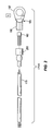
- Fig. 3 is an exploded view of a temperature sensor capable of being used in the automatic choke of Fig. 1 .
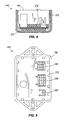
- Fig. 4 is sectional view of the controller of the automatic choke of Fig. 1 .
- Fig. 5 is a top view of the controller of Fig. 4 .
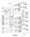
- Figs. 6A and 6B are an electrical schematic of the automatic choke of Fig. 4 .
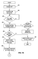
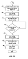
- Figs. 7A-7C are flow diagrams of a method of operating the automatic choke of Fig. 4 .
- Fig. 8 is a graphical representation of the method of Figs. 7A-7C.
- Fig. 9 is a graph representing the optimal number of revolutions versus ambient temperature for a motor in a first relief phase.
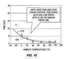
- Fig. 10 is a graph representing the optimal time period versus ambient temperature for the motor in the first relief phase.
- Fig. 11 is a graph representing optimal number of revolutions versus ambient temperature for a motor in a second relief phase.
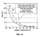
- Fig. 12 is a graph representing the optimal time period versus ambient temperature for the motor in the second relief phase.
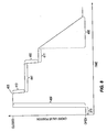
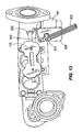
- Fig. 13 is a partial-sectional view of an operator override of the automatic choke of Fig. 1 .
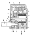
- Fig. 14 is a sectional view of a motor capable of being used in the automatic choke represented in Fig. 13 .
- embodiments of the invention include hardware and software components or modules that, for purposes of discussion, may be illustrated and described as if the majority of the components were implemented in hardware.
- the hardware based aspects of the invention including the electronics, may be implemented in software.
- a plurality of hardware and software based devices, as well as a plurality of different structural components may be utilized to implement the invention.
- the specific mechanical configurations illustrated in the drawings are intended to exemplify embodiments of the invention and that other alternative mechanical constructions are possible.
- Fig. 1 depicts a small engine 100 (e.g., less than about 45 horsepower) incorporating one embodiment of the invention.
- Fig. 2 represents a portion of an apparatus 102 (e.g., a piece of outdoor power equipment) including the small engine 100 having a carburetor 105. It is envisioned, however, that the invention can be used with larger engines having a carburetor.
- the carburetor 105 includes a throttle valve 110 and a choke valve 115 upstream from a cylinder 120.
- the cylinder 120 includes an ignition plug 125, a piston 130, an intake valve 135, and an exhaust valve 140.
- the carburetor 105 mixes air with fuel. The mixture is introduced to the cylinder head past the intake valve 135.
- the piston 130 compresses the mixture and the ignition plug 125 adds a spark to the compressed mixture.
- the resulting combustion byproducts are then exhausted past the exhaust valve 140.
- the choke valve 115 is driven by a motor such as a uni-polar stepper motor 145.
- a motor such as a uni-polar stepper motor 145.
- Other types of motors including a bi-polar stepper motor or a linear motor, can be used to move the choke valve 115.
- the motor 145 is electrically coupled to a controller 150.
- the controller 150 receives inputs from one or more sensors and controls one or more aspects of the engine, including the motor 145, based on the inputs from the sensors. Therefore, the automatic choke may include the choke valve 115, the motor 145, the controller 150, and the sensors. It is also envisioned that the automatic choke can include a mechanical stop 155, which will be discussed further below.
- the controller 150 is coupled to a power source 160, an ignition circuit 165, and a temperature sensor 170.
- the power source 160 provides supply power to the electrical components of the engine 100, including the controller 150.
- the power source can be a standard 12 VDC battery.
- a small engine 100 typically includes an ignition circuit 165 for controlling the ignition or sparking of the engine 100.
- the controller 150 also uses a signal produced by the ignition circuit 165 or by a separate sensor as an indication of the engine rotational speed.
- the controller 150 may also use both the signal produced by the ignition circuit 165 and the signal by the separate sensor to determine the engine rotational speed.
- the rotational speed may be determined by comparing the ignition signal with the sensory output signal. That is, the rotational speed of the power takeoff shaft of the engine 100 has a relation to the ignition of the engine 100.
- the controller 150 uses the ignition circuit or the separate revolution sensor to also obtain the engine rotational speed. Other means can also be used to determine the rotational speed of the engine 100.
- the engine rotational speed can be calculated by a moving average of one or more signals.
- the controller 150 can provide a deactivate (or kill) signal to the ignition circuit 165 to prevent sparking.
- the temperature sensor 170 senses a temperature of the engine 100 and provides a signal having a relation to the sensed temperature to the controller 150.
- An exemplary temperature sensor 170 is a Hokuriku model number NM3103H400H3 thermistor. Other temperature sensors can be used in place of the temperature sensor 170 shown in Fig. 2 .
- the temperature sensor 170A includes a conductor 175 coupled to a thermal sensor 180.
- the thermal sensor 180 is a silicone thermistor, such as a National Semiconductor model no. LN 60-TO92 silicone thermistor.
- the temperature sensor 170A further includes a connector 185 having a first connector or ring portion 190 and a second connector portion 195.
- the thermal sensor 180 is at least partially housed in at least a portion of the second connector portion 195 such that the thermal sensor 180 engages the second connector portion 195.
- a fastener such as potting epoxy, is then used to fasten the thermal sensor 180 to the connector 185.
- a shrink-wrapped insulator 200 can also be placed around the conductor 175, thermal sensor 180, and connector 185 for protection from the elements.
- the ring portion 190 allows the temperature sensor 170 to be coupled to the engine 100 via a fastener, such as a bolt or screw. It is envisioned that the connector 185 can include other shapes or designs in place of the ring portion 190 to promote the coupling of the connector to the engine 100 and the thermal conduction to the thermal sensor 180.
- the controller 150 includes an input/output (I/O) layer or circuit 205.
- the I/O circuit 205 includes I/O connections allowing an electrical system and/or operator to interact with the controller 150. The interaction includes sending information to and/or receiving information from the controller.
- the term "information” is broadly construed to comprise knowledge, instructions, data, codes, values, events, states, measures, outcomes, and similar items, which may be communicated via signals (e.g., analog signals, digital signals) or stored in memory.
- Every connection to/from the controller 150 can be considered an I/O connection.
- the I/O circuit 205 allows the controller 150 to interface with an operator (e.g., via an input and/or output device or interface) or an electrical system (e.g., a programming apparatus, a diagnostic apparatus) not normally associated with the operation of the controller 150.
- the controller 150 is supported by a circuit board 210 surrounded at least partially by a potting material 212 and secured to a housing 215.
- Ports CN1, CN2, and CN3 extend from the housing 215 and receive conductors.
- the conductors and ports CN1, CN2, and CN3 couple the controller 150 to the stepper motor 145, the power source 160, the ignition circuit 165, the temperature sensor 170, and a second electrical system or can be used by a technician.
- the automatic choke 240 can be a stand-alone device that is retrofit onto existing engines 100 by coupling the automatic choke 240 to the engine 100.
- the retrofit of the automatic choke 240 includes coupling the motor 145 to the choke valve 115 and coupling the temperature sensor 170 to the engine 100.
- controller 150 can control other aspects of the engine 100 and/or other aspects of the apparatus 102 driven by the engine 100.
- the controller 150 can be used to control the throttle valve 110 or an ignition circuit, or to operate an accessory component 250 of the apparatus 102.
- the controller 150 includes a power supply 300, a temperature signal conditioning circuit 305, a revolution detection circuit 310, a programmable device such as microcontroller M1, a motor drive circuit 320, and I/O circuitry 205.
- the power supply 300 receives power from the power source 160 and regulates the supply power to one or more desired voltages.
- the power supply 300 includes a voltage regulator REG1, capacitors C1, C2, and C3, and diode D1, the combination of which result in a first supply voltage (e.g., 3.3 VDC) used to power a first set of components of the controller 150.
- the power supply 300 further includes Zener diodes ZD1 and ZD2 for protecting circuitry (e.g., the voltage regulator) of the controller 150 from voltage spikes.
- the voltage regulator REG1 is a Rohm model number BA033CC0FP voltage regulator. Of course, other voltage regulators may be used for other constructions and the magnitudes of the supply voltages can vary.
- the revolution detection circuit 310 is connected to the ignition circuit 165 and provides a revolution signal to the microcontroller M1 having a relation to the rotational movement of the engine 100.
- the microcontroller M1 receives the revolution signal and determines a revolution count and/or a rotational speed of the engine using the signal.
- the revolution signal may be a train of pulses having a relation to a flywheel magnet interacting with an ignition coil or other coil.
- the microcontroller M1 can determine the revolution count by counting the accumulated pulses from a point in time or point in operation, and/or can determine the rotation speed based on the frequency of the pulses.
- the revolution detection circuit 310 includes diode D4; transistor Q1; resistors R4, R5, R6, R7, and R8; and capacitors C6 and C7.
- the circuitry 310 filters and conditions the signal from the coil, and provides a pulse train to the microcontroller M1.
- the temperature signal conditioning circuit 305A includes a resistor R10 and a capacitor C13, both of which are coupled to the temperature sensor 170A of Fig. 3 .
- Alternative temperature sensors such as a thermistor, can include a different conditioning circuit, such as temperature signal conditioning circuitry 305B.
- the temperature sensor conditioning circuit 305B includes resistors R1, R2, and R3; resistor array RB1; diodes D2 and D3; and capacitors C4 and C5. It is also envisioned for some constructions to include other temperature sensors for providing an ambient or comparison temperature.
- a temperature sensor can be supported by or directly coupled to the circuit board 210.
- the microcontroller M1 for the shown construction, is a NEC model no. UPD78F0500 microcontroller.
- the microcontroller M1 includes a processor, volatile memory, nonvolatile memory, an A/D converter, a counter or timer, an oscillator, and a communication port. It is envisioned that the microcontroller M1 may be divided into multiple microcontrollers, that some of the just-listed features of the microcontroller M1 may be separate or distinct from the microcontroller M1 (e.g., the inclusion of a separate oscillator from the microcontroller M1), and that the microcontroller M1 may include other features not listed. It is also envisioned that other hardware devices (e.g., other programmable devices and application specific integrated circuits) and arrangements may be used in place of the microcontroller M1.
- instructions stored in memory 325 are executed by the processor 330 to receive signals from the revolution detection circuit 310 and the temperature sensor 170, to process the information contained in the signals, and to output signals for controlling the motor 145 based on the processed signals and other information (e.g., data) stored in the memory 325.
- instructions stored in the memory 325 are executed by the processor 330 to promote communication with an external device via the I/O circuit 205. It is also envisioned that the processor 330 can execute other instructions for promoting other operations not discussed herein.
- the motor drive circuit 320 receives a control signal from the microcontroller M1 and translates the signal to a drive signal for controlling the motor 145.
- the type and arrangement of the signal may depend in part on the type of motor used.
- the motor for one construction is the uni-polar stepper motor 145.
- the motor driver circuit 320 shown in Fig. 6B may be used with the uni-polar stepper motor 145. More specifically, the illustrated construction includes dual field effect transistors (FETs) F1 and F2; resistor arrays RB5 and RB6; and diodes D10, D11, D12, D13, and D14.
- FETs field effect transistors
- the microcontroller M1 can modify the control of the motor 145 based on the battery voltage. That is, the microcontroller M1 can operate the motor 145 with a first technique if the battery voltage is low and operate the motor 145 with a second technique if the battery voltage is high.
- the automatic choke 240 can include the mechanical stop 155 ( Fig. 2 ) for preventing the choke valve from moving past a known or selected position.
- the mechanical stop 155 allows the motor 145 to step through a predetermined number of degrees of rotation (e.g., 360-degrees of rotation) at predefined times (e.g., upon power up) to guarantee that the valve is at a known location (e.g., fully-closed).
- the microcontroller M1 knows the location of the valve 115 as the motor 145 moves the valve 115 from the known location.
- the microcontroller M1 can receive a signal from a sensor coupled to the motor 145, the signal having a relation to the position of the valve 115.
- a second mechanical stop can be used with one stop 155 corresponding to a first position (e.g., fully closed) and a second stop corresponding to a second position (e.g., fully opened).
- the I/O circuit 205A shown in Fig. 6A promotes serial communication with the microcontroller M1.
- the I/O circuit 205A includes a resistor array RB2, Zenor diodes ZD3, and capacitors C8 and C9.
- the I/O layer can use other wire and/or wireless interfaces for promoting communication with the microcontroller M1.
- the construction shown in Fig. 4 also includes I/O circuit 205B.
- the I/O circuit 205B promotes communication through resistor arrays RB3 and RB4; resistor R9; and capacitors C10, C11, and C12.
- the I/O circuit 205B is used for programming the microcontroller M1 during manufacturing or to re-load the entire program, and the I/O circuit 205A is primarily used for maintenance, including software maintenance.
- a technician or operator can electrically couple a device (such as a hand-held device, personal computer, or similar computing device) to the microcontroller M1 during the Program Mode.
- the Program Mode allows information to be exchanged with the microcontroller M1.
- the information exchange can include downloading configuration information (e.g., data, tables, equations, events) to the microcontroller M1; downloading programming information (e.g., instructions; code) to the microcontroller M1; and uploading event information (e.g., logs; faults; codes; data) from the microcontroller M1.
- configuration information e.g., data, tables, equations, events
- programming information e.g., instructions; code
- event information e.g., logs; faults; codes; data
- configuration information is broadly construed to comprise information used to configure the automatic choke to the engine and/or apparatus containing the automatic choke. It is envisioned that the configuration information can include information for multiple engines/apparatus and an operator can select the configuration information for the specific engine/apparatus containing the automatic choke.
- the technician can also instruct the microcontroller M1 to operate in a Run Mode.
- the Run Mode allows the microcontroller M1 to control the motor 145 in response to the inputs (e.g., temperature and speed signals) received by the microcontroller M1. It is contemplated that the microcontroller M1 can receive embedded signals, via the I/O circuit, indicating the Program and Run Modes.
- the controller 150 can include other output circuitry for providing signals to other devices.
- the controller 150 in Fig. 6A includes an output circuit 205C having resistors R11, R12, R13, R14, R15, R16, R17, R18, and R19; FET F3; diodes D5, D6, D7, D8, and D9; and capacitor C14, the combination of which provides a first output to a light-emitting diode LED and a second output to a solenoid.
- the LED provides a visual output to the operator or technician regarding a state of the automatic choke.
- the solenoid can be used to shut off fuel flow to the engine.
- Fig. 7 which consists of Figs. 7A , 7B , and 7C .
- Fig. 8 is a graphical representation of the position of the choke valve 115 versus time during an exemplary method of operation.
- the engine 100 is off and the controller 150 is powered down.
- Step 375 can occur when a key switch is turned to the "off" position.
- the controller 150 is initialized. This can occur when an operator activates the apparatus 102 (e.g., turns a key to the "on" position), which results in the power source 160 supplying power to the power supply 300.
- the power supply 300 regulates the supply power and provides the power to the controller 150, including the microcontroller M1.
- the microcontroller M1 Upon receiving the power, the microcontroller M1 is initialized, reads instructions and data from memory 325, and initiates the automatic choke 240.
- the microcontroller M1 also starts a counter ECU_TIME.
- step 390 Upon the counter ECU_TIME (step 385) completing a time period, the microcontroller M1 proceeds to step 390, referred to herein as the Choke Control Standby State. While the description thus far discusses the method proceeding from step 385 to step 390, the microcontroller M1 enters the Choke Control Standby State (step 390) under other conditions, some of which are discussed below. Similarly, while the upcoming description discusses the operation proceeding from step 390 to step 395 to step 400, the operation can change the order of steps, as will be exampled below. Before proceeding further, it should be understood that the sequence of the steps discussed herein can vary, one or more steps may occur concurrently, and not all steps may be required.
- the processor 330 obtains one more instructions from the memory 325, interprets the obtained instructions, and executes the interpreted instructions to perform the particular function. For example, if the microcontroller M1 determines an initial temperature, then the processor 330 obtains, interprets, and executes one or more software instructions to acquire and determine an initial temperature for the engine 100.
- the microcontroller M1 determines whether the ECU_TIME counter has passed the time period (e.g. four seconds) and a temperature parameter TEMP (discussed below) is less than a threshold NO_CHOKE_TEMP (discussed below). If both of these conditions are met, then the microcontroller M1 proceeds to step 400. If not, then the microcontroller proceeds to step 705 (discussed below). The microcontroller M1 proceeds to step 400 predominantly upon the key turning to the "on" position and the ECU_TIME counter lapsing.
- the microcontroller M1 issues a signal to the motor drive circuit 320 to drive the motor 145 to the fully-closed position.
- the motor drive circuit 320 causes the motor 145 to rotate an excessive number of degrees to confirm the choke valve 115 is in the fully-closed position.
- the microcontroller M1 sets the parameter MOTOR_POSITION (which identifies the location of the choke valve 115) to zero and a flag CHOKE_STATE_B0 to one.
- a "fully-closed position” may not result in the choke valve 115 being completely closed (e.g., the valve 115 is 100% closed) and a "fully-open position” may not result in the choke valve 115 being completely open (e.g., the valve 115 is 100% open).
- the fully-closed position will be referred to herein as the furthest position the choke valve 115 can close and the fully-open position will be referred to herein as the furthest position the choke valve 115 can open.
- the microcontroller M1 determines an initial (or first relief) position of the choke valve 115. More specifically, the microcontroller M1 accesses the configuration information and obtains one or more data tables for the automatic choke 240. The microcontroller M1 then determines a present temperature, referred to herein as the initial temperature for the engine 100. For example, the microcontroller M1 can acquire a signal from the temperature sensor 170. With the initial temperature and the configuration information, the microcontroller M1 determines the initial position of the choke valve 115.
- the initial position might be fully closed; if the initial temperature is a moderate, ambient temperature, then the initial position might be a partially closed position; and if the initial temperature is an above-ambient, hot temperature (e.g., resulting from a previous running of the engine), then the initial position may be at an almost fully-open position. For the example shown in Fig. 8 , the initial position is not at the fully closed position.
- the microcontroller M1 accesses a data table for the initial position.
- One exemplary table is shown in Table 1.
- the table includes a plurality of discrete points defining a relationship among the present temperature and choke valve position (INITIAL_POS).
- the microcontroller M1 can include instructions for interpolating the acquired data to create values, for example, between the discrete points.
- the stored data can include data for defining equations or other relationships to establish a relationship among the initial choke position and the initial temperature.
- the stored data can vary depending on many factors, such as the model of the engine, model of the original equipment including the engine, the attached accessories, expected environment, etc.
- the stored data can be created empirically and stored in the microcontroller.
- the microcontroller M1 moves the choke valve 115 toward the initial position.
- the parameter MOTOR_TARGET_POS is set to the choke start position (INITIAL_POS) of Table T1.
- the choke valve 115 moves toward the MOTOR_TARGET_POS. If the engine 100 starts (discussed below-step 415) before movement is complete, then the choke start position (INITIAL_POS) is set as the present position of the choke valve 115 (step 420), a flag CHOKE_STATE_B1 is set to one, and the microcontroller M1 proceeds to the first relief phase.
- the flag CHOKE_STATE_B1 is set to one (step 430) and the microcontroller M1 proceeds to the first relief phase.
- MOTOR_TARGET_POS parameter relates to the position at which the choke valve 115 moves toward, and the MOTOR_POSITION parameter related to the position that the choke valve 115 is currently located. Further references to the parameter MOTOR_TARGET_POS and MOTOR_POSITION will not be provided below, but should be apparent from the description below.
- the operator may be cranking the engine 100 before, during, or after step 430.
- the operator can turn the key switch to a "start” position, which results in a start motor cranking the engine 100.
- the operator could have turned the key switch to the "start” position soon after turning the key switch to the "on” position or could have delayed between the movements.
- the revolution detection circuit 310 provides a pulse train to the microcontroller M1.
- the microcontroller M1 senses the pulse train and determines the starter motor is cranking the engine 100 when the frequency of the pulse train is less than a defined frequency. If the engine does not start by a defined time period, the automatic choke can indicate an error through the LED and stop the start routine.
- the microcontroller M1 will continue to monitor the engine speed to determine whether the engine 100 has started.
- the microcontroller M1 can determine the engine 100 has started by determining whether the rotational speed of the engine 100 is greater than a threshold, which is referred to as the start speed.
- the start speed can be slightly greater than the maximum speed of the starter motor.
- a table can be created for the engine start decision based on the initial engine temperature.
- the microcontroller M1 detects whether the engine 100 has started. If yes, then the microcontroller M1 proceeds to step 440 to perform a first relief phase.
- the automatic choke 240 initiates a first relief phase, which is identified as line 441 in Fig. 8 .
- the microcontroller M1 acquires a temperature (hereinafter the "engine-run temperature") after the starting of the engine.
- the microcontroller M1 might use the initial temperature as the engine-run temperature.
- the microcontroller determines a first relief period (e.g., a length of time or periodic count) of the first relief phase 425 (step 435).
- a first relief period e.g., a length of time or periodic count
- An exemplary table for the first relief phase 425 is shown in Table 2.
- the table includes a plurality of discrete points defining a relationship between the engine-run temperature and the first relief period.
- the microcontroller can include instructions for interpolating the acquired data to create values, for example, between the discrete points.
- the stored data can include data for defining equations or other relationships to establish a relationship between the engine-run temperature and the first relief period.
- a relief phase is defined herein as a phase in which the choke valve 115 provides a controlled choke relief to the engine 100; e.g., the choke valve 115 is kept or held at a position for a time period or count, or the choke valve 115 is controllably moved at a defined rate that provides a defined relief.
- the microcontroller M1 maintains the choke valve 115 at the initial position INITIAL_POS until the period lapses for the first relief phase 441 (step 445).
- the period for the first relief phase 441 can be initiated from one of a plurality of points (e.g., when entering step 440 or entering step 405). Other time measurements can be used in place of seconds. For example, the time measurement can be a processor or oscillator count.
- the flag Choke_State.B2 is set to one (step 450).
- the microcontroller M1 determines a second position for the choke valve 115 (step 455), referred to as the second relief position.
- the microcontroller M1 uses the engine-run temperature and configuration information for determining the second relief position.
- the table includes a plurality of discrete points defining a relationship between the engine-run temperature and the second relief position.
- the microcontroller M1 can include instructions for interpolating the acquired data to create values, for example, between the discrete points.
- the stored data can include data for defining equations or other relationships to establish a relationship between the run temperature and the second relief time or the second revolution count. It is also envisioned that the second relief position can be determined based on a current run temperature. [t3] Table 3 Engine-Run Temperature (Deg F.) -20 -10 0 40 50 70 120 Second Relief Position (%) 70 70 65 60 60 55 50
- the microcontroller then moves the choke valve to the second relief position.
- the choke valve 115 is driven to the second relief position.
- the flag CHOKE_STATE_B3 is set to one (step 465).
- the automatic choke 240 initiates a second relief phase.
- the microcontroller M1 uses the engine-run temperature and configuration information for determining an engine revolution count.
- the engine revolution count for the second relief phase 471 can be initiated from the movement of the choke valve to the second relief position. However, in other embodiments, the engine revolution count can begin from the end of the first relief phase 441.
- the table includes a plurality of discrete points defining a relationship between the engine-run temperature and the second revolution count.
- the microcontroller M1 can include instructions for interpolating the acquired data to create values, for example, between the discrete points.
- the stored data can include data for defining equations or other relationships to establish a relationship between the run temperature and the second revolution count. It is also envisioned that the second relief position and the second revolution count can be determined based on a current run temperature.
- Table 4 Engine-Run Temperature (Deg F.) -20 -10 0 40 50 70 120 Second Relief Count (Rotational pulses) 3500 2500 1500 1000 500 200 0
- the microcontroller M1 maintains the choke valve at the second relief position until the monitored revolution count traverses the second relief count (step 475).
- the period for the second relief phase 471 can be initiated from one of a plurality of points (e.g., the end of the first phase or after movement of the choke valve to the second relief position).
- the flag CHOKE_STATE_B4 is set to one (step 480).
- the automatic choke 240 then performs a third relief phase (step 485), which is identified as line 486 in Figs. 6A and 6B .
- the microcontroller M1 uses the engine-run temperature and configuration information for determining the parameters of the third relief phase 486.
- the parameters of the third relief phase 486 include a third relief period.
- the table includes a plurality of discrete points defining a relationship between the engine-run temperature and the third relief period.
- the microcontroller M1 can include instructions for interpolating the acquired data to create values, for example, between the discrete points.
- the stored data can include data for defining equations or other relationships to establish a relationship between the run temperature and an engine revolution count. It is also envisioned that the third relief period can be determined based on a current run temperature. [t5] Table 5 Engine-Run Temperature (Deg F.) -20 -10 0 40 50 70 120 Third Relief Duration (Sec) 4 4 3 2 1 0 0
- the automatic choke 240 moves the choke valve 115 over the duration of the third relief phase 486.
- This movement may also be referred to as a controlled movement.
- the microcontroller M1 determines the remaining angular movement for the valve 115 to fully open. The microcontroller M1 then divides the third relief period proportionally over the remaining angular movement. For example, if the choke valve 115 is moved in one degree increments, if the second relief position is 45 degrees (50%), and the third relief period is 1.5 seconds, then the microcontroller M1 drives the valve one degree every 0.033 seconds (i.e., 1.5 seconds divided by 45 degrees).
- a controlled release can be similarly performed if the release is based on revolution count instead of time.
- the microcontroller M1 determines that the third relief phase 486 is complete and sets the flag CHOKE_STATE_B5 equal to one. Once the choke valve 115 obtains the fully-open position, the parameter MOTOR_TARGET_POS is set as full open position, the present position parameter MOTOR_POSITION is set as full open position. The microcontroller maintains the choke valve at these positions until the engine shuts down or the detection of a safety switch. The sensing of whether the engine 100 shuts down can be based on engine rotational speed. For example, if the rotational speed is less than a minimum value for a time period, then the microcontroller M1 assumes the engine 100 has shut down and returns to step 375.
- the automatic choke 240 includes multiple phases for controlling the position of the choke valve 115.
- the length of the first relief phase 441 is based on time
- the length of the second relief phase 471 is based on revolution count.
- Figs. 9 , 10 , 11 , and 12 provide empirical test data for an engine 100 run at multiple engine speeds. The data includes optimal points for the engine 100 to transition from a first valve position to a second valve position (shown in Figs. 9 and 10 ) at multiple temperatures, and optimal points for the motor to transition from the second valve position to the third valve position (shown in Figs. 11 and 12 ) at multiple temperatures. As shown in Figs.
- time provides more consistent trending over multiple engine speeds between the first valve position and the second valve position than revolution count. That is, the trend lines 615 and 620 for high and low engine speeds, respectively, are more similar to each other than the trend lines 605 and 610 for high and low engine speeds, respectively. As shown in Figs. 11 and 12 , revolution count provides more consistent trending for multiple engine speeds between approximately 75% and 0% than does time. That is, the trend lines 625 and 630 for high and low engine speeds, respectively, are more similar to each other than the trend lines 635 and 640 for high and low engine speeds. Therefore, for the motor tested in Figs. 9 , 10 , 11 , and 12 , time is a better control parameter for the first phase and revolution count is a better control parameter for the second phase.
- the microcontroller M1 further includes nonvolatile memory that stores choke operation information (e.g., a latest choke valve position, a latest "flag" of the algorithm). As the process traverses particular operations, the nonvolatile memory stores operation information, such as the flag. If the engine 100 stops or deactivates before completing the movement of the choke valve 115, the microcontroller M1 can retrieve the previously stored operation information and control the automatic choke 240 based on the stored operation information and based on other conditions. This allows the automatic choke 240 to reduce the time to perform the startup routine, and reduce the amount of exhaust caused by an overly-enriched fuel mixture.
- choke operation information e.g., a latest choke valve position, a latest "flag" of the algorithm.
- the microcontroller M1 determines whether the engine rotational speed signal (e.g., based on the ignition signal) was removed (or "cut") as a result of engine overload. For example, if the rotational speed signal goes slower (e.g., the microcontroller M1 detects a slower speed, such as cranking speed) and then the signal is suspended, the microcontroller M1 then determines that the engine 100 stalled by overload. If the engine 100 stops as a result of overload during cranking RPM (e.g., prior to the engine-start speed), then the microcontroller M1 can re-initiate the control sequence.
- the engine rotational speed signal e.g., based on the ignition signal
- the microcontroller M1 determines that the engine 100 stalled by overload. If the engine 100 stops as a result of overload during cranking RPM (e.g., prior to the engine-start speed), then the microcontroller M1 can re-initiate the control sequence.
- the microcontroller M1 can adjust the starting sequence using the previously stored flag information, or the microcontroller M1 can re-initiate the control sequence.
- the microcontroller M1 determines whether the rotational speed signal was removed or interrupted as a result of a safety switch, such as a seat switch, being activated. For example, if the engine rotational speed signal is suspended without detecting a slower speed, such as the cranking speed, then the microcontroller M1 determines that the rotational speed signal was interrupted by a safety switch. That is, the safety switch initially causes the removal and the later return of the ignition signal, thereby restarting the engine without any cranking. If the ignition signal was removed as a result of a safety switch, the microcontroller M1 waits or holds for a time period (e.g., 5 seconds), and then determines the rotational speed of the engine 100.
- a safety switch such as a seat switch
- the microcontroller M1 can modify the operation of the automatic choke based on the returning rotational speed.
- the microcontroller M1 can use the previously stored flag information to adjust the starting sequence. If the microcontroller M1 does not use previously-stored flag information, then one or more phases of the control sequence can be skipped. Alternatively, if the rotational speed is less than the threshold, then the microcontroller M1 can re-initiate the control sequence (e.g., return to the initial position).
- the microcontroller M1 determines whether the power was removed as a result of a safety switch being activated. If the power signal was removed as a result of a safety switch, which can be determined if the ignition signal returns at power-up, the microcontroller M1 waits a time period (e.g., 5 seconds), and then determines the rotational speed of the engine 100. The microcontroller M1 can modify the operation of the automatic choke based on the rotational speed. For example, if the rotational speed is greater than a threshold (e.g., the engine-start speed), then the microcontroller M1 uses the previously stored flag information to adjust the starting sequence.
- a threshold e.g., the engine-start speed
- microcontroller M1 If the microcontroller M1 does not use previously-stored flag information, then one or more phases of the control sequence can be skipped. Alternatively, if the rotational speed is less than the threshold, then the microcontroller M1 can re-initiate the control sequence (e.g., return to the initial position).
- the engine rotational speed may be faster than the engine-start speed, or the cranking speed, before the automatic choke 240 finishes initializing. It is envisioned that the microcontroller M1 can recognize this situation, move the choke valve 115 to a position between fully open and fully closed, and start the process from that position. The rotational travel of the choke valve 115 can be the same as or larger than the full travel to obtain the fully open position since the choke valve 115 started from the modified initial position. It is also envisioned that the control sequence can skip one or more phases. For example, the control sequence may start from step 455 with the assumption that the first relief phase is unnecessary.
- the automatic choke 240 includes a sensor for sensing a parameter having a relation to the load on the engine.
- the sensor can be a load-MAP (manifold air pressure) sensor.
- the sensor can be the revolution sensor, where the microcontroller determines a rotational speed.
- the rotational speed in some apparatus 102, can have a relation to the load of the apparatus.
- the load sensor can be used to adjust the valve position if the automatic choke 240 senses a change in the load. For example, if the load is increased while the automatic choke 240 is in the process of the choke routine, the air-fuel mixture may be too rich, or too far from the desired air/fuel ratio, for the additional load.
- the automatic choke 240 can adjust the valve position to provide a richer mixture to compensate for the additional load.
- the automatic choke 240 includes a second temperature sensor to be used for comparison with the sensor 170.
- the second sensor can be coupled to the printed circuit board (PCB) for sensing a temperature of the PCB. Since the PCB is made from a different material than the engine housing, to which the sensor 170 can be directly coupled a temperature differential may occur depending on whether the engine has been recently started.
- the microcontroller M1 can use this information to adjust the starting sequence.
- the microcontroller M1 uses the previously stored flag information to adjust the starting sequence.
- a threshold e.g., for example two degrees Fahrenheit
- the microcontroller M1 uses the previously stored flag information to adjust the starting sequence.
- the microcontroller M1 might assume that the engine has been dormant and starts at step 375.
- the microcontroller M1 can determine whether to proceed to a different point in the process (other than 405) based on the flags ENGINE_STATE_B1 through B3 and the flags CHOKE_STATE_B0 through B6. For a specific example, if the flag ENGINE_STATE_B3 is equal to one and the flag CHOKE_STATE_B3 is one, but the flag CHOKE_STATE_B4 is zero, then the microcontroller M1 can proceed to step 475. That is, the microcontroller M1 uses stored flags and status information to adjust the control of the automatic choke 240. Other examples using the ENGINE_STATE flags and the CHOKE_STATE flags can be accomplished similarly.
- the microcontroller M1 determines whether an engine temperature, which can be a current temperature or a previously stored temperature, is less than a threshold NO_CHOKE_TEMP.
- the threshold NO_CHOKE_TEMP provides an indication of whether the engine temperature is sufficient such that no choke is required. For example, the engine may have been just running. If the process proceeds from step 395 to step 705, then the microcontroller M1 proceeds to move the choke valve 115 to the fully open position. Once the choke valve is fully open, the microprocessor proceeds to step 500.
- the microcontroller M1 compares the engine temperature to the circuit board temperature when the microcontroller M1 confirms that the actual engine RPM is above the start speed. If the difference between the two temperatures is greater than a threshold, then the microcontroller M1 can vary a parameter of at least one of the relief phases. For example, the microcontroller M1 can determine a ratio based on the temperature difference. The ratio can then be applied to the first relief time, the second relief count, and/or the third relief time. The use of the ratio can be in addition to adjusting the startup sequence based on the latest flag information.
- the engine 100 includes a manual choke 800 that overrides the automatic choke 240.
- the engine 100 includes a choke lever 805, a choke link 810, and a motor lever 815 that couple the motor 145 to the choke valve 115.
- a manual operation lever 820 can be coupled to the motor lever 815. When moved by an operator, the manual operation lever 820 can override the automatic choke 240. This allows manual operation of the choke valve 115 when the automatic choke 240 is not performing to the satisfaction of the operator.
- a mechanical clutch is coupled to or integrated with the motor 145.
- the mechanical clutch can be integrated with a motor gearing that couples a rotor shaft (discussed below) to the motor lever 815.
- the clutch slips when an operator moves the operation lever 820, even if the motor 115 is energized. This allows an operator to move the choke valve 115 regardless of the operation of the motor 145. This construction also allows control of the choke valve 115 even if the motor 145 does not operate.
- the motor 145 includes a housing 825 that supports a bushing 830.
- An output shaft 835 rotates in the bushing 830 and couples to the motor lever 815.
- a stator 840 having windings 845.
- the windings 845 controllably generate a magnetic field that interacts with a magnetic field of the rotor 855 (e.g., a magnetic field produced by magnets 850 of the rotor 855).
- the rotor 855 is interconnected with (e.g., coupled to or integrated with) a rotor shaft 860 supported by one or more bearings.
- the rotor shaft 860 is coupled to the output shaft 835 via gears 865, 870, 875, and 880.
- the gears 865, 870, 875, and 880 cause the output shaft 835 to rotate in response to the rotor shaft 860.
- Pins 885 support a circuit board 890 having a motor controller attached thereto.
- the motor controller provides the voltage (or current) to the stator windings 545 to achieve the varying magnetic field.
- the motor 145 further includes clutch washers 895. Clutch washers 895 provide a friction fit between the output gear 880 and the output shaft 835 such that, when an excessive load is applied to the shaft 835, the shaft 835 slips with respect to the clutch washers 895.
- the invention proves a new and useful engine with an automatic choke.
- the invention also provides a new and useful method of operating an automatic choke for an engine.
Abstract
Description
- This application claims the benefit of
U.S. Patent Application Nos. 61/059,503 filed June 6, 2008 61/056,230 filed May 27, 2008 61/056,223 filed May 27, 2008 - The invention relates to an automatic choke for an engine, particularly a small engine. The invention also relates to a method of operating the automatic choke.
- Small engines having a carburetor are used in various apparatus, including lawn and garden equipment (e.g., lawn mowers, lawn tractors, blowers), generators, pressure washers, snow throwers, agricultural equipment, outboard engines and other outdoor power equipment. The carburetor can include a throttle and a choke. The choke provides a rich fuel-air mixture upon start-up of the engine to sustain the combustion reaction, and the throttle valve position is responsive to the load on the engine.
- In many small engines, the choke is actuated manually. However, some small engines include an automatic choke. For example, it is known to control a choke valve with a thermally responsive mechanism.
- In one embodiment, the automatic choke of the invention controls the choke valve during one or more relief periods, or phases, any of which can be based on an engine temperature. For example, the automatic choke can operate in three relief phases. The first relief phase maintains the choke valve at a first position for a first time period. The second relief phase maintains the choke valve at a second position for a number or count of engine revolutions. The third relief phase transitions the choke valve from the second position to the fully open position over a second time period. The first and second positions can be the same, and/or can be based on a single engine temperature or based on distinct engine temperatures. Further, the first and second time periods and the revolution count can be based on a single (or the same) engine temperature or can be based on distinct (or different) engine temperatures.
- In another embodiment, the invention provides an automatic choke for an engine having a choke valve. The automatic choke includes a motor configured to be connected to the choke valve, a temperature sensor configured to be connected to the engine, and a controller electrically connected to the motor and the temperature sensor. The controller can also be electrically connected to an ignition circuit of the engine. The controller includes an electronic circuit such as a programmable device. In one construction, the controller is configured to generate a motor control signal to move the choke valve to a first position, determine a time period to hold the choke valve at the first position, generate the motor control signal to move the choke valve from the first position to the second position, determine a count to hold the choke valve at the second position, and generate the motor control signal to move the choke valve to a fully-open position.
- In another construction, the controller is configured to store position information related to the first position, store a flag associated with the first position, determine the engine has re-started, and control the automatic choke with the stored position information based on the flag and the determination that the engine has re-started. In yet another construction, the controller can be configured to determine the engine is being restarted, determine a temperature value based on the temperature signal after the determination that the engine is being restarted, and direct the choke valve to a fully-open position without providing choke relief based on the temperature value indicating the engine temperature is greater than a threshold.
- In another embodiment, the invention provides an engine and an apparatus with the automatic choke.
- Other aspects of the invention will become apparent by consideration of the detailed description and accompanying drawings.
-
Fig. 1 is a perspective view of a small engine having an automatic choke. -
Fig. 2 is a schematic representation of an apparatus including the engine ofFig. 1 . -
Fig. 3 is an exploded view of a temperature sensor capable of being used in the automatic choke ofFig. 1 . -
Fig. 4 is sectional view of the controller of the automatic choke ofFig. 1 . -
Fig. 5 is a top view of the controller ofFig. 4 . -
Figs. 6A and6B are an electrical schematic of the automatic choke ofFig. 4 . -
Figs. 7A-7C are flow diagrams of a method of operating the automatic choke ofFig. 4 . -
Fig. 8 is a graphical representation of the method ofFigs. 7A-7C. -
Fig. 9 is a graph representing the optimal number of revolutions versus ambient temperature for a motor in a first relief phase. -
Fig. 10 is a graph representing the optimal time period versus ambient temperature for the motor in the first relief phase. -
Fig. 11 is a graph representing optimal number of revolutions versus ambient temperature for a motor in a second relief phase. -
Fig. 12 is a graph representing the optimal time period versus ambient temperature for the motor in the second relief phase. -
Fig. 13 is a partial-sectional view of an operator override of the automatic choke ofFig. 1 . -
Fig. 14 is a sectional view of a motor capable of being used in the automatic choke represented inFig. 13 . - Before any embodiments of the invention are explained in detail, it is to be understood that the invention is not limited in its application to the details of construction and the arrangement of components set forth in the following description or illustrated in the following drawings. The invention is capable of other embodiments and of being practiced or of being carried out in various ways. Also, it is to be understood that the phraseology and terminology used herein is for the purpose of description and should not be regarded as limiting. The use of "including," "comprising," or "having" and variations thereof herein is meant to encompass the items listed thereafter and equivalents thereof as well as additional items.
- Although directional references, such as upper, lower, downward, upward, rearward, bottom, front, rear, etc., may be made herein in describing the drawings, these references are made relative to the drawings (as normally viewed) for convenience. These directions are not intended to be taken literally or limit the invention in any form. In addition, terms such as "first", "second", and "third" may be used herein for purposes of description and are not intended to indicate or imply relative importance or significance. Similarly, the use of capitalization used herein is for the purpose of description and is not intended to indicate or imply any importance or significance.
- It should be understood that embodiments of the invention include hardware and software components or modules that, for purposes of discussion, may be illustrated and described as if the majority of the components were implemented in hardware. However, one of ordinary skill in the art, and based on a reading of this detailed description, would recognize that, in at least one embodiment, the hardware based aspects of the invention, including the electronics, may be implemented in software. As such, it should be noted that a plurality of hardware and software based devices, as well as a plurality of different structural components, may be utilized to implement the invention. Furthermore, and as described in subsequent paragraphs, the specific mechanical configurations illustrated in the drawings are intended to exemplify embodiments of the invention and that other alternative mechanical constructions are possible.
-
Fig. 1 depicts a small engine 100 (e.g., less than about 45 horsepower) incorporating one embodiment of the invention.Fig. 2 represents a portion of an apparatus 102 (e.g., a piece of outdoor power equipment) including thesmall engine 100 having acarburetor 105. It is envisioned, however, that the invention can be used with larger engines having a carburetor. - The
carburetor 105 includes athrottle valve 110 and achoke valve 115 upstream from acylinder 120. Thecylinder 120 includes anignition plug 125, apiston 130, anintake valve 135, and anexhaust valve 140. Thecarburetor 105 mixes air with fuel. The mixture is introduced to the cylinder head past theintake valve 135. Thepiston 130 compresses the mixture and theignition plug 125 adds a spark to the compressed mixture. The resulting combustion byproducts are then exhausted past theexhaust valve 140. - The
choke valve 115 is driven by a motor such as auni-polar stepper motor 145. Other types of motors, including a bi-polar stepper motor or a linear motor, can be used to move thechoke valve 115. Themotor 145 is electrically coupled to acontroller 150. As discussed below, thecontroller 150 receives inputs from one or more sensors and controls one or more aspects of the engine, including themotor 145, based on the inputs from the sensors. Therefore, the automatic choke may include thechoke valve 115, themotor 145, thecontroller 150, and the sensors. It is also envisioned that the automatic choke can include amechanical stop 155, which will be discussed further below. - Referring further to
Fig. 2 , thecontroller 150 is coupled to apower source 160, anignition circuit 165, and atemperature sensor 170. Thepower source 160 provides supply power to the electrical components of theengine 100, including thecontroller 150. For example, the power source can be a standard 12 VDC battery. - A
small engine 100 typically includes anignition circuit 165 for controlling the ignition or sparking of theengine 100. Thecontroller 150 also uses a signal produced by theignition circuit 165 or by a separate sensor as an indication of the engine rotational speed. Thecontroller 150 may also use both the signal produced by theignition circuit 165 and the signal by the separate sensor to determine the engine rotational speed. For example, the rotational speed may be determined by comparing the ignition signal with the sensory output signal. That is, the rotational speed of the power takeoff shaft of theengine 100 has a relation to the ignition of theengine 100. Thecontroller 150 uses the ignition circuit or the separate revolution sensor to also obtain the engine rotational speed. Other means can also be used to determine the rotational speed of theengine 100. For example, it is contemplated that the engine rotational speed can be calculated by a moving average of one or more signals. Additionally, thecontroller 150 can provide a deactivate (or kill) signal to theignition circuit 165 to prevent sparking. - The
temperature sensor 170 senses a temperature of theengine 100 and provides a signal having a relation to the sensed temperature to thecontroller 150. Anexemplary temperature sensor 170 is a Hokuriku model number NM3103H400H3 thermistor. Other temperature sensors can be used in place of thetemperature sensor 170 shown inFig. 2 . - For example, an
alternative temperature sensor 170A is shown inFig. 3 . Thetemperature sensor 170A includes aconductor 175 coupled to athermal sensor 180. In one construction, thethermal sensor 180 is a silicone thermistor, such as a National Semiconductor model no. LN 60-TO92 silicone thermistor. Thetemperature sensor 170A further includes aconnector 185 having a first connector orring portion 190 and asecond connector portion 195. Thethermal sensor 180 is at least partially housed in at least a portion of thesecond connector portion 195 such that thethermal sensor 180 engages thesecond connector portion 195. A fastener, such as potting epoxy, is then used to fasten thethermal sensor 180 to theconnector 185. A shrink-wrappedinsulator 200 can also be placed around theconductor 175,thermal sensor 180, andconnector 185 for protection from the elements. Thering portion 190 allows thetemperature sensor 170 to be coupled to theengine 100 via a fastener, such as a bolt or screw. It is envisioned that theconnector 185 can include other shapes or designs in place of thering portion 190 to promote the coupling of the connector to theengine 100 and the thermal conduction to thethermal sensor 180. - Referring back to
Fig. 2 , thecontroller 150 includes an input/output (I/O) layer or circuit 205. The I/O circuit 205 includes I/O connections allowing an electrical system and/or operator to interact with thecontroller 150. The interaction includes sending information to and/or receiving information from the controller. As used herein, the term "information" is broadly construed to comprise knowledge, instructions, data, codes, values, events, states, measures, outcomes, and similar items, which may be communicated via signals (e.g., analog signals, digital signals) or stored in memory. - Before proceeding further, it should be understood that every connection to/from the
controller 150 can be considered an I/O connection. However, unless stated otherwise herein, it is assumed that the I/O circuit 205 allows thecontroller 150 to interface with an operator (e.g., via an input and/or output device or interface) or an electrical system (e.g., a programming apparatus, a diagnostic apparatus) not normally associated with the operation of thecontroller 150. - With reference to
Fig. 4 , thecontroller 150 is supported by acircuit board 210 surrounded at least partially by apotting material 212 and secured to ahousing 215. Ports CN1, CN2, and CN3 (Fig. 5 ), extend from thehousing 215 and receive conductors. The conductors and ports CN1, CN2, and CN3 couple thecontroller 150 to thestepper motor 145, thepower source 160, theignition circuit 165, thetemperature sensor 170, and a second electrical system or can be used by a technician. As shown inFigs. 4 and 5 , theautomatic choke 240 can be a stand-alone device that is retrofit onto existingengines 100 by coupling theautomatic choke 240 to theengine 100. The retrofit of theautomatic choke 240 includes coupling themotor 145 to thechoke valve 115 and coupling thetemperature sensor 170 to theengine 100. - It is also envisioned that the
controller 150 can control other aspects of theengine 100 and/or other aspects of theapparatus 102 driven by theengine 100. For example, thecontroller 150 can be used to control thethrottle valve 110 or an ignition circuit, or to operate anaccessory component 250 of theapparatus 102. - An electrical schematic of the
controller 150 is shown inFigs. 6A and6B . Thecontroller 150 includes apower supply 300, a temperature signal conditioning circuit 305, a revolution detection circuit 310, a programmable device such as microcontroller M1, amotor drive circuit 320, and I/O circuitry 205. - The
power supply 300 receives power from thepower source 160 and regulates the supply power to one or more desired voltages. In the illustrated construction, thepower supply 300 includes a voltage regulator REG1, capacitors C1, C2, and C3, and diode D1, the combination of which result in a first supply voltage (e.g., 3.3 VDC) used to power a first set of components of thecontroller 150. Thepower supply 300 further includes Zener diodes ZD1 and ZD2 for protecting circuitry (e.g., the voltage regulator) of thecontroller 150 from voltage spikes. In one construction, the voltage regulator REG1 is a Rohm model number BA033CC0FP voltage regulator. Of course, other voltage regulators may be used for other constructions and the magnitudes of the supply voltages can vary. - The revolution detection circuit 310 is connected to the
ignition circuit 165 and provides a revolution signal to the microcontroller M1 having a relation to the rotational movement of theengine 100. The microcontroller M1 receives the revolution signal and determines a revolution count and/or a rotational speed of the engine using the signal. For example, the revolution signal may be a train of pulses having a relation to a flywheel magnet interacting with an ignition coil or other coil. The microcontroller M1 can determine the revolution count by counting the accumulated pulses from a point in time or point in operation, and/or can determine the rotation speed based on the frequency of the pulses. In the illustrated construction, the revolution detection circuit 310 includes diode D4; transistor Q1; resistors R4, R5, R6, R7, and R8; and capacitors C6 and C7. The circuitry 310 filters and conditions the signal from the coil, and provides a pulse train to the microcontroller M1. - The temperature
signal conditioning circuit 305A includes a resistor R10 and a capacitor C13, both of which are coupled to thetemperature sensor 170A ofFig. 3 . Alternative temperature sensors, such as a thermistor, can include a different conditioning circuit, such as temperaturesignal conditioning circuitry 305B. The temperaturesensor conditioning circuit 305B includes resistors R1, R2, and R3; resistor array RB1; diodes D2 and D3; and capacitors C4 and C5. It is also envisioned for some constructions to include other temperature sensors for providing an ambient or comparison temperature. For example, a temperature sensor can be supported by or directly coupled to thecircuit board 210. - The microcontroller M1, for the shown construction, is a NEC model no. UPD78F0500 microcontroller. The microcontroller M1 includes a processor, volatile memory, nonvolatile memory, an A/D converter, a counter or timer, an oscillator, and a communication port. It is envisioned that the microcontroller M1 may be divided into multiple microcontrollers, that some of the just-listed features of the microcontroller M1 may be separate or distinct from the microcontroller M1 (e.g., the inclusion of a separate oscillator from the microcontroller M1), and that the microcontroller M1 may include other features not listed. It is also envisioned that other hardware devices (e.g., other programmable devices and application specific integrated circuits) and arrangements may be used in place of the microcontroller M1.
- In operation of the microcontroller M1, during Run Mode (discussed below), instructions (e.g., in the form of code) stored in
memory 325 are executed by theprocessor 330 to receive signals from the revolution detection circuit 310 and thetemperature sensor 170, to process the information contained in the signals, and to output signals for controlling themotor 145 based on the processed signals and other information (e.g., data) stored in thememory 325. In Program Mode (discussed below), instructions stored in thememory 325 are executed by theprocessor 330 to promote communication with an external device via the I/O circuit 205. It is also envisioned that theprocessor 330 can execute other instructions for promoting other operations not discussed herein. - Referring again to
Figs. 6A and6B , themotor drive circuit 320 receives a control signal from the microcontroller M1 and translates the signal to a drive signal for controlling themotor 145. The type and arrangement of the signal may depend in part on the type of motor used. For example, the motor for one construction is theuni-polar stepper motor 145. Themotor driver circuit 320 shown inFig. 6B may be used with theuni-polar stepper motor 145. More specifically, the illustrated construction includes dual field effect transistors (FETs) F1 and F2; resistor arrays RB5 and RB6; and diodes D10, D11, D12, D13, and D14. It is also envisioned that the microcontroller M1 can modify the control of themotor 145 based on the battery voltage. That is, the microcontroller M1 can operate themotor 145 with a first technique if the battery voltage is low and operate themotor 145 with a second technique if the battery voltage is high. - Before proceeding further, it should be understood that the
automatic choke 240 can include the mechanical stop 155 (Fig. 2 ) for preventing the choke valve from moving past a known or selected position. Themechanical stop 155 allows themotor 145 to step through a predetermined number of degrees of rotation (e.g., 360-degrees of rotation) at predefined times (e.g., upon power up) to guarantee that the valve is at a known location (e.g., fully-closed). Based on this initial position, the microcontroller M1 knows the location of thevalve 115 as themotor 145 moves thevalve 115 from the known location. In other constructions, the microcontroller M1 can receive a signal from a sensor coupled to themotor 145, the signal having a relation to the position of thevalve 115. It is also envisioned that a second mechanical stop can be used with onestop 155 corresponding to a first position (e.g., fully closed) and a second stop corresponding to a second position (e.g., fully opened). - The I/
O circuit 205A shown inFig. 6A promotes serial communication with the microcontroller M1. The I/O circuit 205A includes a resistor array RB2, Zenor diodes ZD3, and capacitors C8 and C9. Of course, the I/O layer can use other wire and/or wireless interfaces for promoting communication with the microcontroller M1. For example, the construction shown inFig. 4 also includes I/O circuit 205B. The I/O circuit 205B promotes communication through resistor arrays RB3 and RB4; resistor R9; and capacitors C10, C11, and C12. In one embodiment, the I/O circuit 205B is used for programming the microcontroller M1 during manufacturing or to re-load the entire program, and the I/O circuit 205A is primarily used for maintenance, including software maintenance. - For the construction shown, a technician or operator can electrically couple a device (such as a hand-held device, personal computer, or similar computing device) to the microcontroller M1 during the Program Mode. The Program Mode allows information to be exchanged with the microcontroller M1. The information exchange can include downloading configuration information (e.g., data, tables, equations, events) to the microcontroller M1; downloading programming information (e.g., instructions; code) to the microcontroller M1; and uploading event information (e.g., logs; faults; codes; data) from the microcontroller M1. It should be apparent that the program mode allows the operator to program the automatic choke to a
specific apparatus 102. - As used herein, the term "configuration information" is broadly construed to comprise information used to configure the automatic choke to the engine and/or apparatus containing the automatic choke. It is envisioned that the configuration information can include information for multiple engines/apparatus and an operator can select the configuration information for the specific engine/apparatus containing the automatic choke.
- The technician can also instruct the microcontroller M1 to operate in a Run Mode. The Run Mode allows the microcontroller M1 to control the
motor 145 in response to the inputs (e.g., temperature and speed signals) received by the microcontroller M1. It is contemplated that the microcontroller M1 can receive embedded signals, via the I/O circuit, indicating the Program and Run Modes. - The
controller 150 can include other output circuitry for providing signals to other devices. For example, thecontroller 150 inFig. 6A includes anoutput circuit 205C having resistors R11, R12, R13, R14, R15, R16, R17, R18, and R19; FET F3; diodes D5, D6, D7, D8, and D9; and capacitor C14, the combination of which provides a first output to a light-emitting diode LED and a second output to a solenoid. The LED provides a visual output to the operator or technician regarding a state of the automatic choke. The solenoid can be used to shut off fuel flow to the engine. - One method of operating the
automatic choke 240 is shown inFig. 7 , which consists ofFigs. 7A ,7B , and7C .Fig. 8 is a graphical representation of the position of thechoke valve 115 versus time during an exemplary method of operation. Atstep 375, theengine 100 is off and thecontroller 150 is powered down. Step 375 can occur when a key switch is turned to the "off" position. Atstep 380, thecontroller 150 is initialized. This can occur when an operator activates the apparatus 102 (e.g., turns a key to the "on" position), which results in thepower source 160 supplying power to thepower supply 300. Thepower supply 300 regulates the supply power and provides the power to thecontroller 150, including the microcontroller M1. Upon receiving the power, the microcontroller M1 is initialized, reads instructions and data frommemory 325, and initiates theautomatic choke 240. The microcontroller M1 also starts a counter ECU_TIME. - Upon the counter ECU_TIME (step 385) completing a time period, the microcontroller M1 proceeds to step 390, referred to herein as the Choke Control Standby State. While the description thus far discusses the method proceeding from
step 385 to step 390, the microcontroller M1 enters the Choke Control Standby State (step 390) under other conditions, some of which are discussed below. Similarly, while the upcoming description discusses the operation proceeding fromstep 390 to step 395 to step 400, the operation can change the order of steps, as will be exampled below. Before proceeding further, it should be understood that the sequence of the steps discussed herein can vary, one or more steps may occur concurrently, and not all steps may be required. - Also, it should be understood that, when the microcontroller M1 performs an operation, the
processor 330 obtains one more instructions from thememory 325, interprets the obtained instructions, and executes the interpreted instructions to perform the particular function. For example, if the microcontroller M1 determines an initial temperature, then theprocessor 330 obtains, interprets, and executes one or more software instructions to acquire and determine an initial temperature for theengine 100. - At
step 395, the microcontroller M1 determines whether the ECU_TIME counter has passed the time period (e.g. four seconds) and a temperature parameter TEMP (discussed below) is less than a threshold NO_CHOKE_TEMP (discussed below). If both of these conditions are met, then the microcontroller M1 proceeds to step 400. If not, then the microcontroller proceeds to step 705 (discussed below). The microcontroller M1 proceeds to step 400 predominantly upon the key turning to the "on" position and the ECU_TIME counter lapsing. - At
step 400, the microcontroller M1 issues a signal to themotor drive circuit 320 to drive themotor 145 to the fully-closed position. In one construction, themotor drive circuit 320 causes themotor 145 to rotate an excessive number of degrees to confirm thechoke valve 115 is in the fully-closed position. After the motor has initialized (i.e., fully closes), then the microcontroller M1 sets the parameter MOTOR_POSITION (which identifies the location of the choke valve 115) to zero and a flag CHOKE_STATE_B0 to one. - Before proceeding further, it should be understood that a "fully-closed position" may not result in the
choke valve 115 being completely closed (e.g., thevalve 115 is 100% closed) and a "fully-open position" may not result in thechoke valve 115 being completely open (e.g., thevalve 115 is 100% open). However, the fully-closed position will be referred to herein as the furthest position thechoke valve 115 can close and the fully-open position will be referred to herein as the furthest position thechoke valve 115 can open. - At
step 405, the microcontroller M1 determines an initial (or first relief) position of thechoke valve 115. More specifically, the microcontroller M1 accesses the configuration information and obtains one or more data tables for theautomatic choke 240. The microcontroller M1 then determines a present temperature, referred to herein as the initial temperature for theengine 100. For example, the microcontroller M1 can acquire a signal from thetemperature sensor 170. With the initial temperature and the configuration information, the microcontroller M1 determines the initial position of thechoke valve 115. For example, if the initial temperature is a cold, ambient temperature, then the initial position might be fully closed; if the initial temperature is a moderate, ambient temperature, then the initial position might be a partially closed position; and if the initial temperature is an above-ambient, hot temperature (e.g., resulting from a previous running of the engine), then the initial position may be at an almost fully-open position. For the example shown inFig. 8 , the initial position is not at the fully closed position. - In one exemplary operation, the microcontroller M1 accesses a data table for the initial position. One exemplary table is shown in Table 1. The table includes a plurality of discrete points defining a relationship among the present temperature and choke valve position (INITIAL_POS). The microcontroller M1 can include instructions for interpolating the acquired data to create values, for example, between the discrete points. In other constructions, the stored data can include data for defining equations or other relationships to establish a relationship among the initial choke position and the initial temperature.
[t1] Table 1 Initial Temp. (Deg F.) -20 -10 0 40 50 70 120 Initial position (%) 100 100 100 100 95 90 85 - It should also be understood that the stored data can vary depending on many factors, such as the model of the engine, model of the original equipment including the engine, the attached accessories, expected environment, etc. The stored data can be created empirically and stored in the microcontroller.
- During
step 410, the microcontroller M1 moves thechoke valve 115 toward the initial position. For example, the parameter MOTOR_TARGET_POS is set to the choke start position (INITIAL_POS) of Table T1. Thechoke valve 115 moves toward the MOTOR_TARGET_POS. If theengine 100 starts (discussed below-step 415) before movement is complete, then the choke start position (INITIAL_POS) is set as the present position of the choke valve 115 (step 420), a flag CHOKE_STATE_B1 is set to one, and the microcontroller M1 proceeds to the first relief phase. When thechoke valve 115 obtains the choke start position (i.e., MOTOR_TARGET_POS-step 425), then the flag CHOKE_STATE_B1 is set to one (step 430) and the microcontroller M1 proceeds to the first relief phase. It should be apparent that the MOTOR_TARGET_POS parameter relates to the position at which thechoke valve 115 moves toward, and the MOTOR_POSITION parameter related to the position that thechoke valve 115 is currently located. Further references to the parameter MOTOR_TARGET_POS and MOTOR_POSITION will not be provided below, but should be apparent from the description below. - It should be understood that the operator may be cranking the
engine 100 before, during, or afterstep 430. For example, the operator can turn the key switch to a "start" position, which results in a start motor cranking theengine 100. The operator could have turned the key switch to the "start" position soon after turning the key switch to the "on" position or could have delayed between the movements. During cranking, the revolution detection circuit 310 provides a pulse train to the microcontroller M1. The microcontroller M1 senses the pulse train and determines the starter motor is cranking theengine 100 when the frequency of the pulse train is less than a defined frequency. If the engine does not start by a defined time period, the automatic choke can indicate an error through the LED and stop the start routine. - The microcontroller M1 will continue to monitor the engine speed to determine whether the
engine 100 has started. Typically, the microcontroller M1 can determine theengine 100 has started by determining whether the rotational speed of theengine 100 is greater than a threshold, which is referred to as the start speed. For example, the start speed can be slightly greater than the maximum speed of the starter motor. Alternatively, a table can be created for the engine start decision based on the initial engine temperature. - At
step 435, the microcontroller M1 detects whether theengine 100 has started. If yes, then the microcontroller M1 proceeds to step 440 to perform a first relief phase. - At
step 440, theautomatic choke 240 initiates a first relief phase, which is identified asline 441 inFig. 8 . For thefirst relief phase 441, the microcontroller M1 acquires a temperature (hereinafter the "engine-run temperature") after the starting of the engine. Alternatively, the microcontroller M1 might use the initial temperature as the engine-run temperature. - With the engine-run temperature and configuration information, the microcontroller determines a first relief period (e.g., a length of time or periodic count) of the first relief phase 425 (step 435). An exemplary table for the
first relief phase 425 is shown in Table 2. The table includes a plurality of discrete points defining a relationship between the engine-run temperature and the first relief period. The microcontroller can include instructions for interpolating the acquired data to create values, for example, between the discrete points. In other constructions, the stored data can include data for defining equations or other relationships to establish a relationship between the engine-run temperature and the first relief period. A relief phase is defined herein as a phase in which thechoke valve 115 provides a controlled choke relief to theengine 100; e.g., thechoke valve 115 is kept or held at a position for a time period or count, or thechoke valve 115 is controllably moved at a defined rate that provides a defined relief.[t2] Table 2 Engine-Run Temperature (Deg F.) -20 -10 0 40 50 70 120 First Relief Duration (Sec) 6 4 2 0.5 .3 .1 0 - At
step 440, the microcontroller M1 maintains thechoke valve 115 at the initial position INITIAL_POS until the period lapses for the first relief phase 441 (step 445). The period for thefirst relief phase 441 can be initiated from one of a plurality of points (e.g., when enteringstep 440 or entering step 405). Other time measurements can be used in place of seconds. For example, the time measurement can be a processor or oscillator count. After thefirst relief phase 441 ends, the flag Choke_State.B2 is set to one (step 450). - After the first relief phase, the microcontroller M1 determines a second position for the choke valve 115 (step 455), referred to as the second relief position. For the second relief position, the microcontroller M1 uses the engine-run temperature and configuration information for determining the second relief position.
- An exemplary table for the second relief position is shown in Table 3. The table includes a plurality of discrete points defining a relationship between the engine-run temperature and the second relief position. The microcontroller M1 can include instructions for interpolating the acquired data to create values, for example, between the discrete points. In other constructions, the stored data can include data for defining equations or other relationships to establish a relationship between the run temperature and the second relief time or the second revolution count. It is also envisioned that the second relief position can be determined based on a current run temperature.
[t3] Table 3 Engine-Run Temperature (Deg F.) -20 -10 0 40 50 70 120 Second Relief Position (%) 70 70 65 60 60 55 50 - The microcontroller then moves the choke valve to the second relief position. At
step 460, thechoke valve 115 is driven to the second relief position. After completing the movement, the flag CHOKE_STATE_B3 is set to one (step 465). - At
step 470, theautomatic choke 240 initiates a second relief phase. For the second relief phase 471 (Fig. 8 ), the microcontroller M1 uses the engine-run temperature and configuration information for determining an engine revolution count. The engine revolution count for thesecond relief phase 471 can be initiated from the movement of the choke valve to the second relief position. However, in other embodiments, the engine revolution count can begin from the end of thefirst relief phase 441. - An exemplary table for the
second relief phase 471 is shown in Table 4. The table includes a plurality of discrete points defining a relationship between the engine-run temperature and the second revolution count. The microcontroller M1 can include instructions for interpolating the acquired data to create values, for example, between the discrete points. In other constructions, the stored data can include data for defining equations or other relationships to establish a relationship between the run temperature and the second revolution count. It is also envisioned that the second relief position and the second revolution count can be determined based on a current run temperature.[t4] Table 4 Engine-Run Temperature (Deg F.) -20 -10 0 40 50 70 120 Second Relief Count (Rotational pulses) 3500 2500 1500 1000 500 200 0 - The microcontroller M1 maintains the choke valve at the second relief position until the monitored revolution count traverses the second relief count (step 475). The period for the
second relief phase 471 can be initiated from one of a plurality of points (e.g., the end of the first phase or after movement of the choke valve to the second relief position). Upon completion of the run relief position, the flag CHOKE_STATE_B4 is set to one (step 480). - The
automatic choke 240 then performs a third relief phase (step 485), which is identified asline 486 inFigs. 6A and6B . For thethird relief phase 486, the microcontroller M1 uses the engine-run temperature and configuration information for determining the parameters of thethird relief phase 486. In one operation, the parameters of thethird relief phase 486 include a third relief period. - An exemplary table for the
third relief phase 486 is shown in Table 5. The table includes a plurality of discrete points defining a relationship between the engine-run temperature and the third relief period. The microcontroller M1 can include instructions for interpolating the acquired data to create values, for example, between the discrete points. In other constructions, the stored data can include data for defining equations or other relationships to establish a relationship between the run temperature and an engine revolution count. It is also envisioned that the third relief period can be determined based on a current run temperature.[t5] Table 5 Engine-Run Temperature (Deg F.) -20 -10 0 40 50 70 120 Third Relief Duration (Sec) 4 4 3 2 1 0 0 - In the exemplary operation, the
automatic choke 240 moves thechoke valve 115 over the duration of thethird relief phase 486. This movement may also be referred to as a controlled movement. For example, the microcontroller M1 determines the remaining angular movement for thevalve 115 to fully open. The microcontroller M1 then divides the third relief period proportionally over the remaining angular movement. For example, if thechoke valve 115 is moved in one degree increments, if the second relief position is 45 degrees (50%), and the third relief period is 1.5 seconds, then the microcontroller M1 drives the valve one degree every 0.033 seconds (i.e., 1.5 seconds divided by 45 degrees). A controlled release can be similarly performed if the release is based on revolution count instead of time. - At
step 490, the microcontroller M1 then determines that thethird relief phase 486 is complete and sets the flag CHOKE_STATE_B5 equal to one. Once thechoke valve 115 obtains the fully-open position, the parameter MOTOR_TARGET_POS is set as full open position, the present position parameter MOTOR_POSITION is set as full open position. The microcontroller maintains the choke valve at these positions until the engine shuts down or the detection of a safety switch. The sensing of whether theengine 100 shuts down can be based on engine rotational speed. For example, if the rotational speed is less than a minimum value for a time period, then the microcontroller M1 assumes theengine 100 has shut down and returns to step 375. - As discussed above, the
automatic choke 240 includes multiple phases for controlling the position of thechoke valve 115. In one construction, the length of thefirst relief phase 441 is based on time, and the length of thesecond relief phase 471 is based on revolution count.Figs. 9 ,10 ,11 , and12 provide empirical test data for anengine 100 run at multiple engine speeds. The data includes optimal points for theengine 100 to transition from a first valve position to a second valve position (shown inFigs. 9 and10 ) at multiple temperatures, and optimal points for the motor to transition from the second valve position to the third valve position (shown inFigs. 11 and12 ) at multiple temperatures. As shown inFigs. 9 and10 , time provides more consistent trending over multiple engine speeds between the first valve position and the second valve position than revolution count. That is, thetrend lines trend lines Figs. 11 and12 , revolution count provides more consistent trending for multiple engine speeds between approximately 75% and 0% than does time. That is, thetrend lines trend lines Figs. 9 ,10 ,11 , and12 , time is a better control parameter for the first phase and revolution count is a better control parameter for the second phase. - As discussed for the detailed example of
Fig. 7 , the microcontroller M1 further includes nonvolatile memory that stores choke operation information (e.g., a latest choke valve position, a latest "flag" of the algorithm). As the process traverses particular operations, the nonvolatile memory stores operation information, such as the flag. If theengine 100 stops or deactivates before completing the movement of thechoke valve 115, the microcontroller M1 can retrieve the previously stored operation information and control theautomatic choke 240 based on the stored operation information and based on other conditions. This allows theautomatic choke 240 to reduce the time to perform the startup routine, and reduce the amount of exhaust caused by an overly-enriched fuel mixture. - In another construction, the microcontroller M1 determines whether the engine rotational speed signal (e.g., based on the ignition signal) was removed (or "cut") as a result of engine overload. For example, if the rotational speed signal goes slower (e.g., the microcontroller M1 detects a slower speed, such as cranking speed) and then the signal is suspended, the microcontroller M1 then determines that the
engine 100 stalled by overload. If theengine 100 stops as a result of overload during cranking RPM (e.g., prior to the engine-start speed), then the microcontroller M1 can re-initiate the control sequence. Alternatively, if theengine 100 stops as a result of overload after cranking RPM (e.g., after the engine-start speed), then the microcontroller M1 can adjust the starting sequence using the previously stored flag information, or the microcontroller M1 can re-initiate the control sequence. - In yet another construction, the microcontroller M1 determines whether the rotational speed signal was removed or interrupted as a result of a safety switch, such as a seat switch, being activated. For example, if the engine rotational speed signal is suspended without detecting a slower speed, such as the cranking speed, then the microcontroller M1 determines that the rotational speed signal was interrupted by a safety switch. That is, the safety switch initially causes the removal and the later return of the ignition signal, thereby restarting the engine without any cranking. If the ignition signal was removed as a result of a safety switch, the microcontroller M1 waits or holds for a time period (e.g., 5 seconds), and then determines the rotational speed of the
engine 100. The microcontroller M1 can modify the operation of the automatic choke based on the returning rotational speed. The microcontroller M1 can use the previously stored flag information to adjust the starting sequence. If the microcontroller M1 does not use previously-stored flag information, then one or more phases of the control sequence can be skipped. Alternatively, if the rotational speed is less than the threshold, then the microcontroller M1 can re-initiate the control sequence (e.g., return to the initial position). - In a further construction, the microcontroller M1 determines whether the power was removed as a result of a safety switch being activated. If the power signal was removed as a result of a safety switch, which can be determined if the ignition signal returns at power-up, the microcontroller M1 waits a time period (e.g., 5 seconds), and then determines the rotational speed of the
engine 100. The microcontroller M1 can modify the operation of the automatic choke based on the rotational speed. For example, if the rotational speed is greater than a threshold (e.g., the engine-start speed), then the microcontroller M1 uses the previously stored flag information to adjust the starting sequence. If the microcontroller M1 does not use previously-stored flag information, then one or more phases of the control sequence can be skipped. Alternatively, if the rotational speed is less than the threshold, then the microcontroller M1 can re-initiate the control sequence (e.g., return to the initial position). - In some constructions, the engine rotational speed may be faster than the engine-start speed, or the cranking speed, before the
automatic choke 240 finishes initializing. It is envisioned that the microcontroller M1 can recognize this situation, move thechoke valve 115 to a position between fully open and fully closed, and start the process from that position. The rotational travel of thechoke valve 115 can be the same as or larger than the full travel to obtain the fully open position since thechoke valve 115 started from the modified initial position. It is also envisioned that the control sequence can skip one or more phases. For example, the control sequence may start fromstep 455 with the assumption that the first relief phase is unnecessary. - In another construction, the
automatic choke 240 includes a sensor for sensing a parameter having a relation to the load on the engine. For example, the sensor can be a load-MAP (manifold air pressure) sensor. In other constructions, the sensor can be the revolution sensor, where the microcontroller determines a rotational speed. The rotational speed, in someapparatus 102, can have a relation to the load of the apparatus. The load sensor can be used to adjust the valve position if theautomatic choke 240 senses a change in the load. For example, if the load is increased while theautomatic choke 240 is in the process of the choke routine, the air-fuel mixture may be too rich, or too far from the desired air/fuel ratio, for the additional load. Theautomatic choke 240 can adjust the valve position to provide a richer mixture to compensate for the additional load. - In yet another construction, the
automatic choke 240 includes a second temperature sensor to be used for comparison with thesensor 170. For example, the second sensor can be coupled to the printed circuit board (PCB) for sensing a temperature of the PCB. Since the PCB is made from a different material than the engine housing, to which thesensor 170 can be directly coupled a temperature differential may occur depending on whether the engine has been recently started. The microcontroller M1 can use this information to adjust the starting sequence. - For example, if the temperature differential between the first and second temperature sensors is greater than a threshold (e.g., for example two degrees Fahrenheit), then the microcontroller M1 uses the previously stored flag information to adjust the starting sequence. Alternatively, if the two temperatures are substantially similar, then the microcontroller M1 might assume that the engine has been dormant and starts at
step 375. - A more specific example regarding the adjustment of the control sequence of
Fig. 7 is now provided. When theengine 100 stops for a time period, then the flag ENGINE_STATE_B1 is set to one. When the engine stalls due to excess load, then the flag ENGINE_STATE_B2 is set to one. When the engine stops due to a safety switch, then the flag ENGINE_STATE_B3 is set to one. These engine states can occur at almost any operation in the sequence ofFig. 7 . As best shown bystep 700, the sequence returns to step 390 when one of the flags ENGINE_STATE_B1, B2, or B3 occur. Afterstep 395 but before step 400 (not shown), the microcontroller M1 can determine whether to proceed to a different point in the process (other than 405) based on the flags ENGINE_STATE_B1 through B3 and the flags CHOKE_STATE_B0 through B6. For a specific example, if the flag ENGINE_STATE_B3 is equal to one and the flag CHOKE_STATE_B3 is one, but the flag CHOKE_STATE_B4 is zero, then the microcontroller M1 can proceed to step 475. That is, the microcontroller M1 uses stored flags and status information to adjust the control of theautomatic choke 240. Other examples using the ENGINE_STATE flags and the CHOKE_STATE flags can be accomplished similarly. - Referring again to step 395, the microcontroller M1 determines whether an engine temperature, which can be a current temperature or a previously stored temperature, is less than a threshold NO_CHOKE_TEMP. The threshold NO_CHOKE_TEMP provides an indication of whether the engine temperature is sufficient such that no choke is required. For example, the engine may have been just running.
If the process proceeds fromstep 395 to step 705, then the microcontroller M1 proceeds to move thechoke valve 115 to the fully open position.
Once the choke valve is fully open, the microprocessor proceeds to step 500. - In another exemplary method of operation, the microcontroller M1 compares the engine temperature to the circuit board temperature when the microcontroller M1 confirms that the actual engine RPM is above the start speed. If the difference between the two temperatures is greater than a threshold, then the microcontroller M1 can vary a parameter of at least one of the relief phases. For example, the microcontroller M1 can determine a ratio based on the temperature difference. The ratio can then be applied to the first relief time, the second relief count, and/or the third relief time. The use of the ratio can be in addition to adjusting the startup sequence based on the latest flag information.
- In yet another additional construction (
Fig. 13 ), theengine 100 includes amanual choke 800 that overrides theautomatic choke 240. Theengine 100 includes achoke lever 805, achoke link 810, and amotor lever 815 that couple themotor 145 to thechoke valve 115. Amanual operation lever 820 can be coupled to themotor lever 815. When moved by an operator, themanual operation lever 820 can override theautomatic choke 240. This allows manual operation of thechoke valve 115 when theautomatic choke 240 is not performing to the satisfaction of the operator. - In the more specific construction of
Fig. 13 , a mechanical clutch is coupled to or integrated with themotor 145. The mechanical clutch can be integrated with a motor gearing that couples a rotor shaft (discussed below) to themotor lever 815. The clutch slips when an operator moves theoperation lever 820, even if themotor 115 is energized. This allows an operator to move thechoke valve 115 regardless of the operation of themotor 145. This construction also allows control of thechoke valve 115 even if themotor 145 does not operate. - One
exemplary motor 145 including a clutch is shown inFig. 14 . Themotor 145 includes ahousing 825 that supports abushing 830. Anoutput shaft 835 rotates in thebushing 830 and couples to themotor lever 815. Enclosed within the housing is astator 840 havingwindings 845. Thewindings 845 controllably generate a magnetic field that interacts with a magnetic field of the rotor 855 (e.g., a magnetic field produced bymagnets 850 of the rotor 855). Therotor 855 is interconnected with (e.g., coupled to or integrated with) arotor shaft 860 supported by one or more bearings. Therotor shaft 860 is coupled to theoutput shaft 835 viagears gears output shaft 835 to rotate in response to therotor shaft 860.Pins 885 support acircuit board 890 having a motor controller attached thereto. The motor controller provides the voltage (or current) to the stator windings 545 to achieve the varying magnetic field. Themotor 145 further includesclutch washers 895.Clutch washers 895 provide a friction fit between theoutput gear 880 and theoutput shaft 835 such that, when an excessive load is applied to theshaft 835, theshaft 835 slips with respect to theclutch washers 895. That is, under normal operation, the friction fit of theclutch washers 895 allows themotor 145 to control thechoke valve 115 as described above. However, when an operator operates themanual operation lever 820, theshaft 835 slips regardless of the movement of therotor shaft 860. - Therefore, the invention proves a new and useful engine with an automatic choke. The invention also provides a new and useful method of operating an automatic choke for an engine.
Claims (23)
- An automatic choke (240) configured to be connected to an engine (100), the automatic choke (240) comprising:a choke valve (115);a motor (145) configured to be connected to the choke valve (240) and to move the choke valve (115) in response to a motor control signal;a temperature sensor (170) configured to provide a temperature signal related to a temperature of the engine (100); anda controller (150) electrically connected to the motor (145) and to the temperature sensor (170) and including an electronic circuit (210), the controller (150) being configured to
generate a first motor control signal that causes the motor (145) to move the choke valve (115) to a first position,
determine a time period to hold the choke valve (115) at the first position, the determination of the time period being based on a temperature value, the temperature value having a relation to the temperature signal,
generate a second motor control signal to move the choke valve (115) from the first position toward the second position,
determine a count to hold the choke valve (115) at the second position, the determination of the count being based on the temperature value, the count having a relation to a number of engine revolutions, and
generate a third motor control signal to move the choke valve (115) toward a fully-open position. - An automatic choke (240) as set forth in claim 1, wherein the controller (150) is configured to generate a fourth motor control signal to move the choke valve (115) toward a fully closed position prior to generating the first motor control signal.
- An automatic choke (240) as set forth in claim 1 or claim 2, wherein the controller (150) is further configured to determine the first position of the choke valve (115) based on the temperature value, and to determine the second position of the choke valve (115) based on the temperature value.
- An automatic choke (240) as set forth in any preceding claim, wherein the controller (150) is configured to set the first position based on a position of the choke valve (115) upon starting the engine (100).
- An automatic choke (240) as set forth in claim 3, wherein the temperature value includes a first temperature value and a second temperature value, wherein the controller (150) is configured to determine that the first position is based on the first temperature value and the controller (150) is configured to determine that the second position is based on the second temperature value.
- An automatic choke (240) as set forth in any of claims 3 to 5, wherein the temperature value includes a first temperature value and a second temperature value, wherein the controller (150) determines the time period to hold the choke valve (115) based on the first temperature value and determines the count to hold the choke valve (115) based on the second temperature value.
- An automatic choke (240) as set forth in any of claims 4 to 6, wherein the controller (150) is configured to determine the first temperature value prior to the engine (100) starting, and wherein the controller (150) is configured to determine the second temperature value after the engine (100) starts.
- An automatic choke (240) as set forth in any preceding claim, wherein the controller (150) is further configured to determine a second time period to release the choke valve (115) from the second position to the fully open position, and wherein controller (150) is configured to generate the motor control signal to move the choke valve (115) toward the fully-open position over the second time period.
- An automatic choke (240) as set forth in any preceding claim, wherein the automatic choke (240) includes a coil configured to generate a count signal to the electronic circuit (210) as a function of engine speed.
- An automatic choke (240) as set forth in any preceding claim, wherein the electronic circuit (210) includes a programmable device.
- An automatic choke (240) as set forth in any preceding claim, wherein the engine (100) further includes an ignition circuit (165) configured to provide an ignition signal, and wherein the controller (150) determines the count of engine revolutions based on the ignition signal.
- An automatic choke as set forth in any preceding claim, wherein the engine (100) further includes an engine revolution detection circuit (310) configured to provide an engine revolution signal having a relation to the rotation of a shaft of the engine (100), and wherein the controller (150) determines the count of engine revolutions based on the engine revolution signal.
- A method of controlling a choke valve (115) of an engine (100) with a controller (150), the controller (150) having a programmable device and being coupled to a temperature sensor (170) and to a motor (145), the method comprising:determining a temperature value using the temperature sensor (170), the temperature value having a relation to a temperature of the engine (100);moving the choke valve (115) to a first position using the motor (145);determining a time period to hold the choke valve (115) in the first position, the determining of the time period being based on the temperature value;keeping the choke valve (115) at the first position for the time period;moving the choke valve (115) from the first position toward a second position using the motor (145);determining a count related to a number of engine revolutions to hold the choke valve (115) in the second position, the determining of the count being based on the temperature value;keeping the choke valve (115) at the second position for the count; andmoving the choke valve (115) from the second position toward a fully open position.
- A method as set forth in claim 13, wherein the determining a temperature value includes determining a first temperature value and determining a second temperature value, wherein the determining the time period is based on the first temperature value, and wherein the determining the count is based on the second temperature value.
- A method as set forth in claim 14, wherein the determining a first temperature value occurs prior to starting the engine (100), and wherein the determining a second temperature value occurs after the engine (100) starts.
- A method as set forth in any of claims 13 to 15, wherein the choke valve (115) is moved to a fully closed position prior to the moving the choke valve (115) to the first position.
- A method as set forth in any of claims 13 to 16, further comprising determining a second time period to release the choke valve (115) from the second position to the fully open position, and wherein the moving the choke valve (115) from the second position toward a fully open position includes controllably moving the choke valve (115) toward the fully open position during the second time period.
- A method as set forth in any of claims 13 to 17, wherein the determining the count includes accessing a stored count value from a look-up table.
- An automatic choke (240) for controlling a choke valve (115) of an engine (100), the automatic choke (240) comprising a controller (150), a motor (145), a choke valve (115), and a temperature sensor (170), the controller (150) being configured to perform the method of controlling the choke valve (115) of claim 13.
- A method of starting an engine (100) having an automatic choke (240) including a choke valve (115), a motor (145) coupled to the choke valve (115), a controller (150) coupled to the motor (145), and a temperature sensor (170) coupled to the controller (150), the controller (150) having a programmable device, the method comprising:determining a temperature value using the temperature sensor (170), the temperature value having a relation to a temperature of the engine (100);receiving a signal to start the engine (100) with the controller (150);performing a relief phase for the engine (100) with the automatic choke (240), including determining a count related to a number of engine revolutions, the count being based on the temperature value, and performing the relief phase during the count.
- A method as set forth in claim 20, wherein the relief phase is a second relief phase, and the method further comprising:performing a first relief phase for the engine (100) with the automatic choke (240), including determining a time period for the first relief phase based on the temperature value and performing the first relief phase over the time period.
- A method as set forth in claim 21, wherein the first relief phase occurs before the second relief phase.
- A method as set forth in claim 22, and further comprising:performing a third relief phase for the engine (100) with the automatic choke (240), including determining a second time period based on the temperature value, and performing the third relief phase during the second time period.
Applications Claiming Priority (3)
| Application Number | Priority Date | Filing Date | Title |
|---|---|---|---|
| US5622308P | 2008-05-27 | 2008-05-27 | |
| US5623008P | 2008-05-27 | 2008-05-27 | |
| US5950308P | 2008-06-06 | 2008-06-06 |
Publications (2)
| Publication Number | Publication Date |
|---|---|
| EP2128420A2 true EP2128420A2 (en) | 2009-12-02 |
| EP2128420A3 EP2128420A3 (en) | 2012-02-15 |
Family
ID=41056851
Family Applications (2)
| Application Number | Title | Priority Date | Filing Date |
|---|---|---|---|
| EP09251406A Withdrawn EP2128420A3 (en) | 2008-05-27 | 2009-05-27 | Engine with an automatic choke and method of operating an automatic choke for an engine |
| EP09251405A Withdrawn EP2157307A3 (en) | 2008-05-27 | 2009-05-27 | Engine with an automotic choke and method of operating an automatic choke for an engine |
Family Applications After (1)
| Application Number | Title | Priority Date | Filing Date |
|---|---|---|---|
| EP09251405A Withdrawn EP2157307A3 (en) | 2008-05-27 | 2009-05-27 | Engine with an automotic choke and method of operating an automatic choke for an engine |
Country Status (2)
| Country | Link |
|---|---|
| US (3) | US8434444B2 (en) |
| EP (2) | EP2128420A3 (en) |
Cited By (8)
| Publication number | Priority date | Publication date | Assignee | Title |
|---|---|---|---|---|
| EP2472086A1 (en) * | 2010-12-28 | 2012-07-04 | Honda Motor Co., Ltd. | Automatic choke apparatus for carburetor |
| EP2713035A1 (en) * | 2012-09-27 | 2014-04-02 | Honda Motor Co., Ltd. | Initialization processing apparatus for cogeneration system having gas engine |
| WO2015023885A3 (en) * | 2013-08-15 | 2015-06-18 | Kohler Co. | Systems and methods for electronically controlling the position of a choke valve in a carburetor |
| US10054081B2 (en) | 2014-10-17 | 2018-08-21 | Kohler Co. | Automatic starting system |
| EP3333413A3 (en) * | 2016-12-12 | 2018-09-05 | Kohler Co. | Ignition module for internal combustion engine with integrated communication device |
| EP3404251A4 (en) * | 2016-01-15 | 2019-02-13 | Suzhou Cleva Precision Machinery & Technology Co., Ltd. | Portable gasoline tool and electronic ignition system thereof |
| EP3415741A4 (en) * | 2016-01-15 | 2019-06-19 | Suzhou Cleva Precision Machinery & Technology Co., Ltd. | Electric accelerator device and control system thereof |
| EP3404239A4 (en) * | 2016-01-15 | 2019-08-07 | Suzhou Cleva Precision Machinery & Technology Co., Ltd. | Garden tool |
Families Citing this family (17)
| Publication number | Priority date | Publication date | Assignee | Title |
|---|---|---|---|---|
| EP2140548A4 (en) | 2007-03-20 | 2010-06-09 | Tabula Inc | Configurable ic having a routing fabric with storage elements |
| US8434444B2 (en) * | 2008-05-27 | 2013-05-07 | Briggs & Stratton Corporation | Engine with an automatic choke and method of operating an automatic choke for an engine |
| JP4921515B2 (en) * | 2009-04-27 | 2012-04-25 | 本田技研工業株式会社 | Control device for general-purpose internal combustion engine |
| JP5418119B2 (en) * | 2009-09-30 | 2014-02-19 | 日立工機株式会社 | Work machine |
| WO2012002859A1 (en) * | 2010-07-01 | 2012-01-05 | Husqvarna Ab | Method of delivering start-up fuel to an internal combustion engine |
| USD685897S1 (en) | 2010-12-03 | 2013-07-09 | Briggs & Stratton Corporation | Air filter |
| DE202011000519U1 (en) * | 2011-03-09 | 2012-06-12 | Makita Corporation | Engine working device with an internal combustion engine |
| US9628009B2 (en) * | 2011-10-27 | 2017-04-18 | Briggs & Stratton Corporation | Method for monitoring and controlling engine speed |
| US10215130B2 (en) | 2012-02-10 | 2019-02-26 | Briggs & Stratton Corporation | Choke override for an engine |
| US9429107B2 (en) | 2013-02-22 | 2016-08-30 | Briggs & Stratton Corporation | Solenoid autochoke for an engine |
| US9347390B2 (en) * | 2013-03-20 | 2016-05-24 | Ford Global Technologies, Llc | Engine de-choking in response to an engine flood event |
| US9945326B2 (en) | 2015-05-07 | 2018-04-17 | Briggs & Stratton Corporation | Automatic choking mechanism for internal combustion engines |
| US9932936B2 (en) | 2015-11-11 | 2018-04-03 | Briggs & Stratton Corporation | Carburetor choke removal mechanism for pressure washers |
| CN105626285B (en) * | 2016-01-29 | 2019-01-25 | 深圳市力骏泰燃气动力科技有限公司 | A kind of engine mixed gas intelligent regulating system |
| WO2019183427A1 (en) * | 2018-03-22 | 2019-09-26 | Continental Motors, Inc. | Engine ignition timing and power supply system |
| CN111376247A (en) * | 2018-12-28 | 2020-07-07 | 深圳市优必选科技有限公司 | Steering engine calibration method, steering engine calibration device and robot |
| CN111042972A (en) * | 2019-12-31 | 2020-04-21 | 重庆鑫源农机股份有限公司 | Generator start control circuit and generator |
Citations (3)
| Publication number | Priority date | Publication date | Assignee | Title |
|---|---|---|---|---|
| US4433665A (en) * | 1981-03-23 | 1984-02-28 | Nippon Soken, Inc. | Device for controlling choke valve in carburetor for internal combustion engine |
| JPH041455A (en) * | 1990-04-13 | 1992-01-06 | Yanmar Diesel Engine Co Ltd | Electronic control mechanism for gasoline engine |
| EP1574693A1 (en) * | 2004-03-12 | 2005-09-14 | Honda Motor Co., Ltd | Automatic choke |
Family Cites Families (85)
| Publication number | Priority date | Publication date | Assignee | Title |
|---|---|---|---|---|
| US2684057A (en) * | 1949-04-01 | 1954-07-20 | Borg Warner | Electrically actuated automatic choke |
| US2689532A (en) * | 1951-01-09 | 1954-09-21 | Ibm | Nonrotating multipiston radial pump |
| US2764393A (en) * | 1954-05-14 | 1956-09-25 | Charles F Geyer | Manually actuated control attachment for automatic choke |
| US3064953A (en) * | 1960-04-29 | 1962-11-20 | John C Hayes | Manual auxiliary control system for automatic chokes |
| FR1586471A (en) | 1968-09-05 | 1970-02-20 | ||
| FR2114238A5 (en) | 1970-11-20 | 1972-06-30 | Gele Pierre | |
| JPS5432884B2 (en) | 1971-10-25 | 1979-10-17 | ||
| JPS5435261B2 (en) * | 1972-08-10 | 1979-11-01 | ||
| US3837322A (en) | 1973-07-30 | 1974-09-24 | Honda Motor Co Ltd | Carburetor choke |
| JPS5326608B2 (en) | 1974-03-15 | 1978-08-03 | ||
| ZA745824B (en) * | 1974-09-12 | 1975-11-26 | M Schoeman | Supplying fuel to internal combustion engines |
| JPS51136038A (en) * | 1975-05-17 | 1976-11-25 | Yamaha Motor Co Ltd | Internal combustion engine |
| US4011844A (en) * | 1975-06-16 | 1977-03-15 | Honda Giken Kogyo Kabushiki Kaisha | Automatic choke valve apparatus in an internal combustion engine |
| US4005690A (en) | 1975-06-23 | 1977-02-01 | Honda Giken Kogyo Kabushiki Kaisha | Automatic choke valve apparatus in an internal combustion engine |
| US4027640A (en) * | 1975-08-15 | 1977-06-07 | Honda Giken Kogyo Kabushiki Kaisha | Automatic choke valve apparatus in an internal combustion engine |
| ZA756062B (en) * | 1975-09-23 | 1977-04-27 | M Schoeman | Supplying fuel to internal combustion engines |
| US4197767A (en) * | 1978-05-08 | 1980-04-15 | The Bendix Corporation | Warm up control for closed loop engine roughness fuel control |
| JPS54158527A (en) | 1978-06-02 | 1979-12-14 | Hitachi Ltd | Electronic type fuel control device for internal combustion engine |
| US4245317A (en) * | 1978-06-22 | 1981-01-13 | The Bendix Corporation | Start and warm up features for electronic fuel management systems |
| US4246639A (en) | 1978-06-22 | 1981-01-20 | The Bendix Corporation | Start and warm up features for electronic fuel management systems |
| US4292946A (en) * | 1978-11-15 | 1981-10-06 | Nissan Motor Company, Limited | Air-fuel ratio control system |
| DE2927881C2 (en) | 1979-07-11 | 1984-06-28 | Bosch und Pierburg System oHG, 4040 Neuss | Method and device for transitional enrichment in mixture formers |
| US4279841A (en) * | 1979-08-09 | 1981-07-21 | General Motors Corporation | Carburetor with improved choke mechanism |
| US4298549A (en) * | 1979-10-29 | 1981-11-03 | Woodworth Carburetor Corp. Of Nevada | Carburetor |
| US4321902A (en) * | 1980-04-11 | 1982-03-30 | General Motors Corporation | Engine control method |
| JPS5720529A (en) | 1980-07-12 | 1982-02-03 | Honda Motor Co Ltd | Device for controlling fluid flow supplied to internal combustion engine |
| JPS5726236A (en) | 1980-07-23 | 1982-02-12 | Honda Motor Co Ltd | Warming up detector for air to fuel ratio controller of internal combustion engine |
| JPS5726238A (en) | 1980-07-25 | 1982-02-12 | Toyota Motor Corp | Idle rate of revolution controller |
| JPS5732036A (en) * | 1980-08-05 | 1982-02-20 | Honda Motor Co Ltd | Air/fuel ratio feedback control device for internal combustion engine |
| JPS5751936A (en) * | 1980-09-12 | 1982-03-27 | Hitachi Ltd | Controlling and trouble discrimination initializing timing setting system for engine controller |
| JPS5770932A (en) | 1980-10-07 | 1982-05-01 | Honda Motor Co Ltd | Warming-up detector for air fuel ratio controller of internal combustion engine |
| US4530805A (en) | 1980-12-10 | 1985-07-23 | Abbey Harold | Flow regulating carburetors |
| JPS57181955A (en) | 1981-04-30 | 1982-11-09 | Sanshin Ind Co Ltd | Overheat preventer for engine |
| JPS5862373A (en) * | 1981-10-07 | 1983-04-13 | Nippon Denso Co Ltd | Ignition timing control device for internal- combustion engine |
| US4344898A (en) | 1981-12-10 | 1982-08-17 | Aisan Kogyo Kabushiki Kaisha | Carburetor controlling system |
| US4463723A (en) | 1982-04-01 | 1984-08-07 | Acf Industries, Incorporated | Apparatus for controllably opening a carburetor choke valve |
| JPS5996465A (en) | 1982-11-24 | 1984-06-02 | Honda Motor Co Ltd | Fuel feed controller for engine |
| IT1157490B (en) | 1982-12-20 | 1987-02-11 | Weber Spa | CARBURETOR FOR INTERNAL COMBUSTION ENGINES EQUIPPED WITH ELECTRONIC ACTING BODIES SUITABLE TO MAINTAIN THE MINIMUM RPM OF THE ENGINE AND TO CHECK THE POSITION OF THE STARTING BUTTERFLY DURING THE ENGINE EFFICIENCY |
| JPS59136526A (en) * | 1983-01-27 | 1984-08-06 | Honda Motor Co Ltd | Apparatus for controlling complete-combustion opening of throttle valve |
| JPS59190450A (en) * | 1983-04-11 | 1984-10-29 | Honda Motor Co Ltd | Air-fuel ratio controller for internal-combustion engine for car |
| JPS6011640A (en) | 1983-06-29 | 1985-01-21 | Yanmar Diesel Engine Co Ltd | Governing controller for heat pump driving gas engine |
| FR2568631B1 (en) | 1984-08-03 | 1987-01-16 | Solex | CARBURETOR WITH AUTOMATIC STARTING DEVICE |
| US4883616A (en) * | 1984-08-13 | 1989-11-28 | Covey Jr Ray M | Vaporizer/carburetor and method |
| JPS61101659A (en) * | 1984-10-22 | 1986-05-20 | Fuji Heavy Ind Ltd | Autochoke device |
| JPS61157731A (en) | 1984-12-29 | 1986-07-17 | Daihatsu Motor Co Ltd | Warming system of engine for vehicle |
| JPS61275558A (en) * | 1985-05-24 | 1986-12-05 | Honda Motor Co Ltd | Intake secondary air feeder for internal-combustion engine |
| JPS62279259A (en) | 1986-05-28 | 1987-12-04 | Sanshin Ind Co Ltd | Automatic choke device |
| FR2603948B1 (en) * | 1986-09-17 | 1991-01-11 | Solex | ELECTRICAL ASSISTANCE ON SHUTTER |
| JPS63167061A (en) | 1986-12-27 | 1988-07-11 | Honda Motor Co Ltd | Air-fuel ratio control device for internal combustion engine |
| JPH0652062B2 (en) | 1987-01-31 | 1994-07-06 | 三信工業株式会社 | Auto choke device |
| JPH01203626A (en) * | 1988-02-07 | 1989-08-16 | Honda Motor Co Ltd | Starting control device and intake air quantity control device for internal combustion engine |
| JPH0286969A (en) | 1988-09-21 | 1990-03-27 | Kumagai Gumi Co Ltd | Wave pump |
| JP2621120B2 (en) * | 1988-10-19 | 1997-06-18 | 三信工業株式会社 | Fuel supply device for internal combustion engine |
| DE3924353A1 (en) | 1989-07-22 | 1991-02-14 | Prufrex Elektro App | CONTROL SYSTEM FOR THE CARBURETOR OF AN INTERNAL COMBUSTION ENGINE |
| JPH04116256A (en) | 1990-09-04 | 1992-04-16 | Kubota Corp | Electronic governor |
| US5657730A (en) * | 1991-04-12 | 1997-08-19 | Ab Volvo | Method for cold starting piston-type combustion engines and a device for carrying out the method |
| US5146882A (en) * | 1991-08-27 | 1992-09-15 | General Motors Corporation | Method and apparatus for cold starting a spark ignited internal combustion engine fueled with an alcohol-based fuel mixture |
| JP3203440B2 (en) * | 1992-10-08 | 2001-08-27 | 株式会社ユニシアジェックス | Air-fuel ratio feedback control device for internal combustion engine |
| JP3543119B2 (en) * | 1993-09-08 | 2004-07-14 | ヤマハマリン株式会社 | Engine start control device |
| US5611312A (en) | 1995-02-07 | 1997-03-18 | Walbro Corporation | Carburetor and method and apparatus for controlling air/fuel ratio of same |
| JP3764187B2 (en) * | 1995-06-02 | 2006-04-05 | ヤマハマリン株式会社 | Engine start control device |
| US5660765A (en) | 1996-06-26 | 1997-08-26 | Kohler Co. | Thermostatic element for controlling a solenoid operated carburetor choke |
| JPH1030499A (en) | 1996-07-12 | 1998-02-03 | Kubota Corp | Engine equipped with choke valve gear |
| US6012420A (en) * | 1997-12-30 | 2000-01-11 | Briggs & Stratton Corporation | Automatic air inlet control system for an engine |
| JP4116256B2 (en) | 2001-01-10 | 2008-07-09 | 帝人株式会社 | Medical oxygen cylinder |
| CA2437787A1 (en) * | 2001-02-08 | 2002-08-15 | Bombardier Inc. | Systems and methods for automatic carburetor enrichment during cold start |
| WO2003036078A1 (en) * | 2001-10-22 | 2003-05-01 | Yamaha Hatsudoki Kabushiki Kaisha | Autochoke controller |
| JP2003343359A (en) * | 2002-05-30 | 2003-12-03 | Zama Japan Kk | Carburetor |
| JP2004232529A (en) | 2003-01-30 | 2004-08-19 | Toyota Industries Corp | Auto-choke device |
| US7121269B2 (en) * | 2003-04-16 | 2006-10-17 | Michael North | Hot-start solenoid valve |
| US6990969B2 (en) * | 2003-07-30 | 2006-01-31 | Briggs And Stratton Corporation | Automatic choke for an engine |
| DE10335345B4 (en) | 2003-08-01 | 2013-04-18 | Andreas Stihl Ag & Co. Kg | Method for operating a carburetor assembly for an internal combustion engine and carburetor assembly for its implementation |
| TWI268309B (en) | 2004-03-03 | 2006-12-11 | Honda Motor Co Ltd | Device for controlling choke valve of carburetor |
| JP4391275B2 (en) * | 2004-03-09 | 2009-12-24 | 三菱電機株式会社 | Multi-cylinder engine operation control device |
| US7213555B2 (en) * | 2004-03-12 | 2007-05-08 | Honda Motor Co., Ltd. | Automatic choke |
| JP4199688B2 (en) * | 2004-03-18 | 2008-12-17 | 本田技研工業株式会社 | Auto choke device |
| JP4405340B2 (en) | 2004-08-18 | 2010-01-27 | 本田技研工業株式会社 | Electronic controller for carburetor choke valve |
| ES2307095T3 (en) | 2004-08-18 | 2008-11-16 | Honda Motor Co., Ltd. | CARBURETOR ELECTRONIC CONTROL SYSTEM. |
| JP4319111B2 (en) * | 2004-08-26 | 2009-08-26 | 本田技研工業株式会社 | Electric choke device for vaporizer |
| US7171947B2 (en) | 2005-05-27 | 2007-02-06 | Honda Motor Co., Ltd. | Electrically-actuated throttle device for general-purpose engine |
| JP2007023838A (en) | 2005-07-13 | 2007-02-01 | Honda Motor Co Ltd | Auto-choke device of general-purpose internal combustion engine |
| US7487608B2 (en) * | 2005-07-29 | 2009-02-10 | Honda Motor Co., Ltd. | Walk-behind self-propelled snow removing machine |
| JP4523543B2 (en) | 2005-12-14 | 2010-08-11 | 本田技研工業株式会社 | Engine carburetor automatic control device |
| JP4868523B2 (en) * | 2007-04-04 | 2012-02-01 | 京都電機器株式会社 | Auto choke device in engine |
| US8434444B2 (en) * | 2008-05-27 | 2013-05-07 | Briggs & Stratton Corporation | Engine with an automatic choke and method of operating an automatic choke for an engine |
-
2009
- 2009-05-15 US US12/466,583 patent/US8434444B2/en active Active
- 2009-05-15 US US12/466,593 patent/US8219305B2/en active Active
- 2009-05-27 EP EP09251406A patent/EP2128420A3/en not_active Withdrawn
- 2009-05-27 EP EP09251405A patent/EP2157307A3/en not_active Withdrawn
-
2012
- 2012-07-09 US US13/544,544 patent/US8434445B2/en active Active
Patent Citations (3)
| Publication number | Priority date | Publication date | Assignee | Title |
|---|---|---|---|---|
| US4433665A (en) * | 1981-03-23 | 1984-02-28 | Nippon Soken, Inc. | Device for controlling choke valve in carburetor for internal combustion engine |
| JPH041455A (en) * | 1990-04-13 | 1992-01-06 | Yanmar Diesel Engine Co Ltd | Electronic control mechanism for gasoline engine |
| EP1574693A1 (en) * | 2004-03-12 | 2005-09-14 | Honda Motor Co., Ltd | Automatic choke |
Non-Patent Citations (3)
| Title |
|---|
| US 61056223 A 27 May 2008 |
| US 61056230 A 27 May 2008 |
| US 61059503 A 06 June 2008 |
Cited By (14)
| Publication number | Priority date | Publication date | Assignee | Title |
|---|---|---|---|---|
| EP2472086A1 (en) * | 2010-12-28 | 2012-07-04 | Honda Motor Co., Ltd. | Automatic choke apparatus for carburetor |
| US8783664B2 (en) | 2010-12-28 | 2014-07-22 | Honda Motor Co., Ltd. | Automatic choke apparatus for carburetor |
| EP2713035A1 (en) * | 2012-09-27 | 2014-04-02 | Honda Motor Co., Ltd. | Initialization processing apparatus for cogeneration system having gas engine |
| US10240543B2 (en) | 2013-08-15 | 2019-03-26 | Kohler Co. | Integrated ignition and electronic auto-choke module for an internal combustion engine |
| CN104884776A (en) * | 2013-08-15 | 2015-09-02 | 科勒公司 | Systems and methods for electronically controlling fuel-to-air ratio for an internal combustion engine |
| US9464588B2 (en) | 2013-08-15 | 2016-10-11 | Kohler Co. | Systems and methods for electronically controlling fuel-to-air ratio for an internal combustion engine |
| WO2015023885A3 (en) * | 2013-08-15 | 2015-06-18 | Kohler Co. | Systems and methods for electronically controlling the position of a choke valve in a carburetor |
| US10794313B2 (en) | 2013-08-15 | 2020-10-06 | Kohler Co. | Integrated ignition and electronic auto-choke module for an internal combustion engine |
| US10054081B2 (en) | 2014-10-17 | 2018-08-21 | Kohler Co. | Automatic starting system |
| EP3404251A4 (en) * | 2016-01-15 | 2019-02-13 | Suzhou Cleva Precision Machinery & Technology Co., Ltd. | Portable gasoline tool and electronic ignition system thereof |
| EP3415741A4 (en) * | 2016-01-15 | 2019-06-19 | Suzhou Cleva Precision Machinery & Technology Co., Ltd. | Electric accelerator device and control system thereof |
| EP3404239A4 (en) * | 2016-01-15 | 2019-08-07 | Suzhou Cleva Precision Machinery & Technology Co., Ltd. | Garden tool |
| EP3333413A3 (en) * | 2016-12-12 | 2018-09-05 | Kohler Co. | Ignition module for internal combustion engine with integrated communication device |
| US10634111B2 (en) | 2016-12-12 | 2020-04-28 | Kohler Co. | Ignition module for internal combustion engine with integrated communication device |
Also Published As
| Publication number | Publication date |
|---|---|
| EP2157307A2 (en) | 2010-02-24 |
| US20090293828A1 (en) | 2009-12-03 |
| EP2128420A3 (en) | 2012-02-15 |
| US8434444B2 (en) | 2013-05-07 |
| US8219305B2 (en) | 2012-07-10 |
| US20090299614A1 (en) | 2009-12-03 |
| EP2157307A3 (en) | 2012-02-15 |
| US8434445B2 (en) | 2013-05-07 |
| US20120266839A1 (en) | 2012-10-25 |
Similar Documents
| Publication | Publication Date | Title |
|---|---|---|
| EP2128420A2 (en) | Engine with an automatic choke and method of operating an automatic choke for an engine | |
| CN111163845B (en) | Multifunctional engine control and input system | |
| JP4921515B2 (en) | Control device for general-purpose internal combustion engine | |
| US7369933B2 (en) | Simple engine fuel controller | |
| US7171947B2 (en) | Electrically-actuated throttle device for general-purpose engine | |
| US20070012287A1 (en) | Automatic choke control system for general-purpose engine | |
| US8036818B2 (en) | Control apparatus for general-purpose engine | |
| CN108884785B (en) | Fuel supply system for engine warm-up | |
| US8770171B2 (en) | Combustion engine, diagnostic arrangement for a combustion engine and a method for setting a combustion engine | |
| JP3913493B2 (en) | Starter for internal combustion engine | |
| US9410487B2 (en) | Control apparatus for general purpose machine | |
| EP1975395B1 (en) | General-purpose internal combustion engine | |
| JP2009264266A (en) | Control apparatus for general-purpose engine | |
| JP3990358B2 (en) | Auto choke control device | |
| JP2005076522A (en) | Throttle device for general-purpose engine | |
| JP2009264267A (en) | Control apparatus for general-purpose engine | |
| JP3074220B2 (en) | Control device for internal combustion engine | |
| KR0139932B1 (en) | Auxiliary starting ignition advance system control and method for diesel engine | |
| JP2004232529A (en) | Auto-choke device | |
| JP5189675B2 (en) | Engine electronic control unit | |
| JPH0320579B2 (en) | ||
| JPH11324731A (en) | Controller for internal combustion engine |
Legal Events
| Date | Code | Title | Description |
|---|---|---|---|
| PUAI | Public reference made under article 153(3) epc to a published international application that has entered the european phase |
Free format text: ORIGINAL CODE: 0009012 |
|
| AK | Designated contracting states |
Kind code of ref document: A2 Designated state(s): AT BE BG CH CY CZ DE DK EE ES FI FR GB GR HR HU IE IS IT LI LT LU LV MC MK MT NL NO PL PT RO SE SI SK TR |
|
| PUAL | Search report despatched |
Free format text: ORIGINAL CODE: 0009013 |
|
| AK | Designated contracting states |
Kind code of ref document: A3 Designated state(s): AT BE BG CH CY CZ DE DK EE ES FI FR GB GR HR HU IE IS IT LI LT LU LV MC MK MT NL NO PL PT RO SE SI SK TR |
|
| AX | Request for extension of the european patent |
Extension state: AL BA RS |
|
| RIC1 | Information provided on ipc code assigned before grant |
Ipc: F02D 41/06 20060101ALI20120110BHEP Ipc: F02M 1/10 20060101ALI20120110BHEP Ipc: F02M 1/02 20060101AFI20120110BHEP |
|
| STAA | Information on the status of an ep patent application or granted ep patent |
Free format text: STATUS: THE APPLICATION IS DEEMED TO BE WITHDRAWN |
|
| 18D | Application deemed to be withdrawn |
Effective date: 20120817 |