EP2128371B1 - Method for insulating a jamb for exterior joinery work - Google Patents
Method for insulating a jamb for exterior joinery work Download PDFInfo
- Publication number
- EP2128371B1 EP2128371B1 EP09007045A EP09007045A EP2128371B1 EP 2128371 B1 EP2128371 B1 EP 2128371B1 EP 09007045 A EP09007045 A EP 09007045A EP 09007045 A EP09007045 A EP 09007045A EP 2128371 B1 EP2128371 B1 EP 2128371B1
- Authority
- EP
- European Patent Office
- Prior art keywords
- jamb
- chamber
- scale
- shaped
- strips
- Prior art date
- Legal status (The legal status is an assumption and is not a legal conclusion. Google has not performed a legal analysis and makes no representation as to the accuracy of the status listed.)
- Active
Links
- 238000000034 method Methods 0.000 title claims description 16
- 238000005192 partition Methods 0.000 claims description 5
- 239000011810 insulating material Substances 0.000 claims description 4
- 238000005096 rolling process Methods 0.000 claims description 3
- XAGFODPZIPBFFR-UHFFFAOYSA-N aluminium Chemical compound [Al] XAGFODPZIPBFFR-UHFFFAOYSA-N 0.000 description 5
- 229910052782 aluminium Inorganic materials 0.000 description 5
- 239000004411 aluminium Substances 0.000 description 5
- 238000004519 manufacturing process Methods 0.000 description 4
- 238000007789 sealing Methods 0.000 description 4
- 238000009413 insulation Methods 0.000 description 3
- 239000006260 foam Substances 0.000 description 2
- 230000005855 radiation Effects 0.000 description 2
- 229920002994 synthetic fiber Polymers 0.000 description 2
- 239000002131 composite material Substances 0.000 description 1
- 238000001125 extrusion Methods 0.000 description 1
- 239000000463 material Substances 0.000 description 1
- 239000000203 mixture Substances 0.000 description 1
- 230000008092 positive effect Effects 0.000 description 1
- 239000003566 sealing material Substances 0.000 description 1
- 230000009466 transformation Effects 0.000 description 1
Images



Classifications
-
- E—FIXED CONSTRUCTIONS
- E06—DOORS, WINDOWS, SHUTTERS, OR ROLLER BLINDS IN GENERAL; LADDERS
- E06B—FIXED OR MOVABLE CLOSURES FOR OPENINGS IN BUILDINGS, VEHICLES, FENCES OR LIKE ENCLOSURES IN GENERAL, e.g. DOORS, WINDOWS, BLINDS, GATES
- E06B3/00—Window sashes, door leaves, or like elements for closing wall or like openings; Layout of fixed or moving closures, e.g. windows in wall or like openings; Features of rigidly-mounted outer frames relating to the mounting of wing frames
- E06B3/04—Wing frames not characterised by the manner of movement
- E06B3/263—Frames with special provision for insulation
- E06B3/26301—Frames with special provision for insulation with prefabricated insulating strips between two metal section members
- E06B3/26303—Frames with special provision for insulation with prefabricated insulating strips between two metal section members with thin strips, e.g. defining a hollow space between the metal section members
-
- E—FIXED CONSTRUCTIONS
- E06—DOORS, WINDOWS, SHUTTERS, OR ROLLER BLINDS IN GENERAL; LADDERS
- E06B—FIXED OR MOVABLE CLOSURES FOR OPENINGS IN BUILDINGS, VEHICLES, FENCES OR LIKE ENCLOSURES IN GENERAL, e.g. DOORS, WINDOWS, BLINDS, GATES
- E06B3/00—Window sashes, door leaves, or like elements for closing wall or like openings; Layout of fixed or moving closures, e.g. windows in wall or like openings; Features of rigidly-mounted outer frames relating to the mounting of wing frames
- E06B3/04—Wing frames not characterised by the manner of movement
- E06B3/263—Frames with special provision for insulation
- E06B3/2632—Frames with special provision for insulation with arrangements reducing the heat transmission, other than an interruption in a metal section
-
- E—FIXED CONSTRUCTIONS
- E06—DOORS, WINDOWS, SHUTTERS, OR ROLLER BLINDS IN GENERAL; LADDERS
- E06B—FIXED OR MOVABLE CLOSURES FOR OPENINGS IN BUILDINGS, VEHICLES, FENCES OR LIKE ENCLOSURES IN GENERAL, e.g. DOORS, WINDOWS, BLINDS, GATES
- E06B3/00—Window sashes, door leaves, or like elements for closing wall or like openings; Layout of fixed or moving closures, e.g. windows in wall or like openings; Features of rigidly-mounted outer frames relating to the mounting of wing frames
- E06B3/04—Wing frames not characterised by the manner of movement
- E06B3/263—Frames with special provision for insulation
- E06B3/273—Frames with special provision for insulation with prefabricated insulating elements held in position by deformation of portions of the metal frame members
-
- E—FIXED CONSTRUCTIONS
- E06—DOORS, WINDOWS, SHUTTERS, OR ROLLER BLINDS IN GENERAL; LADDERS
- E06B—FIXED OR MOVABLE CLOSURES FOR OPENINGS IN BUILDINGS, VEHICLES, FENCES OR LIKE ENCLOSURES IN GENERAL, e.g. DOORS, WINDOWS, BLINDS, GATES
- E06B3/00—Window sashes, door leaves, or like elements for closing wall or like openings; Layout of fixed or moving closures, e.g. windows in wall or like openings; Features of rigidly-mounted outer frames relating to the mounting of wing frames
- E06B3/04—Wing frames not characterised by the manner of movement
- E06B3/263—Frames with special provision for insulation
- E06B3/2632—Frames with special provision for insulation with arrangements reducing the heat transmission, other than an interruption in a metal section
- E06B2003/26321—Frames with special provision for insulation with arrangements reducing the heat transmission, other than an interruption in a metal section with additional prefab insulating materials in the hollow space
-
- E—FIXED CONSTRUCTIONS
- E06—DOORS, WINDOWS, SHUTTERS, OR ROLLER BLINDS IN GENERAL; LADDERS
- E06B—FIXED OR MOVABLE CLOSURES FOR OPENINGS IN BUILDINGS, VEHICLES, FENCES OR LIKE ENCLOSURES IN GENERAL, e.g. DOORS, WINDOWS, BLINDS, GATES
- E06B3/00—Window sashes, door leaves, or like elements for closing wall or like openings; Layout of fixed or moving closures, e.g. windows in wall or like openings; Features of rigidly-mounted outer frames relating to the mounting of wing frames
- E06B3/04—Wing frames not characterised by the manner of movement
- E06B3/263—Frames with special provision for insulation
- E06B3/2632—Frames with special provision for insulation with arrangements reducing the heat transmission, other than an interruption in a metal section
- E06B2003/26325—Frames with special provision for insulation with arrangements reducing the heat transmission, other than an interruption in a metal section the convection or radiation in a hollow space being reduced, e.g. by subdividing the hollow space
- E06B2003/26327—Frames with special provision for insulation with arrangements reducing the heat transmission, other than an interruption in a metal section the convection or radiation in a hollow space being reduced, e.g. by subdividing the hollow space with separate thin walled inserts
-
- E—FIXED CONSTRUCTIONS
- E06—DOORS, WINDOWS, SHUTTERS, OR ROLLER BLINDS IN GENERAL; LADDERS
- E06B—FIXED OR MOVABLE CLOSURES FOR OPENINGS IN BUILDINGS, VEHICLES, FENCES OR LIKE ENCLOSURES IN GENERAL, e.g. DOORS, WINDOWS, BLINDS, GATES
- E06B3/00—Window sashes, door leaves, or like elements for closing wall or like openings; Layout of fixed or moving closures, e.g. windows in wall or like openings; Features of rigidly-mounted outer frames relating to the mounting of wing frames
- E06B3/04—Wing frames not characterised by the manner of movement
- E06B3/263—Frames with special provision for insulation
- E06B3/2632—Frames with special provision for insulation with arrangements reducing the heat transmission, other than an interruption in a metal section
- E06B2003/26325—Frames with special provision for insulation with arrangements reducing the heat transmission, other than an interruption in a metal section the convection or radiation in a hollow space being reduced, e.g. by subdividing the hollow space
- E06B2003/2633—Frames with special provision for insulation with arrangements reducing the heat transmission, other than an interruption in a metal section the convection or radiation in a hollow space being reduced, e.g. by subdividing the hollow space the insulating strips between the metal sections having ribs extending into the hollow space
-
- E—FIXED CONSTRUCTIONS
- E06—DOORS, WINDOWS, SHUTTERS, OR ROLLER BLINDS IN GENERAL; LADDERS
- E06B—FIXED OR MOVABLE CLOSURES FOR OPENINGS IN BUILDINGS, VEHICLES, FENCES OR LIKE ENCLOSURES IN GENERAL, e.g. DOORS, WINDOWS, BLINDS, GATES
- E06B3/00—Window sashes, door leaves, or like elements for closing wall or like openings; Layout of fixed or moving closures, e.g. windows in wall or like openings; Features of rigidly-mounted outer frames relating to the mounting of wing frames
- E06B3/04—Wing frames not characterised by the manner of movement
- E06B3/263—Frames with special provision for insulation
- E06B2003/26349—Details of insulating strips
- E06B2003/2635—Specific form characteristics
- E06B2003/26352—Specific form characteristics hollow
-
- E—FIXED CONSTRUCTIONS
- E06—DOORS, WINDOWS, SHUTTERS, OR ROLLER BLINDS IN GENERAL; LADDERS
- E06B—FIXED OR MOVABLE CLOSURES FOR OPENINGS IN BUILDINGS, VEHICLES, FENCES OR LIKE ENCLOSURES IN GENERAL, e.g. DOORS, WINDOWS, BLINDS, GATES
- E06B3/00—Window sashes, door leaves, or like elements for closing wall or like openings; Layout of fixed or moving closures, e.g. windows in wall or like openings; Features of rigidly-mounted outer frames relating to the mounting of wing frames
- E06B3/04—Wing frames not characterised by the manner of movement
- E06B3/263—Frames with special provision for insulation
- E06B2003/26349—Details of insulating strips
- E06B2003/26387—Performing extra functions
- E06B2003/26389—Holding sealing strips or forming sealing abutments
Definitions
- the present invention concerns a method for insulating a jamb for exterior joinery work such as doors, windows or the like.
- door or window jambs are formed of two jambs, i.e. what are called the outer scale and inner scale, usually made of aluminium, and at least two thermally insulating strips in the shape of jambs provided at a distance from one another between the outer scale and the inner scale so as to form a thermal interruption, whereby said strips are fixed in grooves of the outer scale and of the inner scale with their longitudinal edges during the assembly of the door or window jamb.
- the strips are usually clamped in the grooves by what is called the roll-in technique, whereby the outer edges of the aforesaid grooves are plastically transformed by folding down said edges towards the inside by means of a roller or the like.
- a good thermal interruption makes sure that there is not any cold radiation from the outer scale to the inner scale.
- thermal interruptions are usually focussed on a single type of window or door jamb and, consequently, they cannot be universally applied, which also makes their application expensive.
- This assembly method restricts the length of the jambs, however, for example to a length of 6 meters.
- DE 35 45 092 A1 shows a known method for insulating a jamb according to the preamble of claim 1 and a known insulated jamb according to the preamble of claim 3.
- the invention aims to remedy one or several of the above-mentioned disadvantages and to obtain considerable insulating values for the thermal interruption of aluminium systems for manufacturing exterior joinery work in a simple and cheap manner.
- the invention concerns a method for insulating a jamb for exterior joinery work of the above-mentioned type, according to claim 1.
- the width of the thermal bridge As a function of the width of the thermal bridge, it is possible to create several compartments, thanks to a combination of the above-mentioned strips and multi-chamber jambs, which can efficiently restrict the cold transfer from the outside to the inside.
- a limited series of strip forms and multi-chamber jambs can provide for an efficient thermal insulation for several types and forms of window and door jambs, with a restricted supply of said elements.
- the basic form of the strips is preferably the conventional Omega structure.
- the cross ribs thereby serve as partitions which stop the cold radiation.
- the I-shape provides the multi-chamber jamb with a strong and robust design which resists any transformation of the jamb.
- the multi-chamber jambs are profiled such that, after the assembly of the window or door jamb, they are kept in place in a clamping manner between the outer scale and inner scale by means of conical clamping as well as by means of slantingly provided distance ribs.
- the present invention also concerns an insulated jamb for exterior joinery work such as a door or window jamb or the like, according to claim 3.
- FIG. 1 schematically shows a jamb 1 of the exterior joinery work of a window, a door or the like, whereby the jamb 1 is in this case composed of two parallel jambs 2-3 made of aluminium or another material, i.e. an outer scale 2 and an inner scale 3 respectively, which are connected to one another by means of two thermally insulating strips 4-5 made of a heat-insulating material, for example a synthetic material or a composite material.
- a heat-insulating material for example a synthetic material or a composite material.
- the grooves 8 are defined by ribs 9 provided crosswise on the above-mentioned walls 6-7 at a distance from one another.
- the insulating strips 4-5 have the conventional Omega structure, forming the base part 10 of the strip, and whereby the longitudinal edges 11 of the Omega widen so as to fix the longitudinal edges 11 in the grooves 8 of the inner and outer scale 2-3.
- One or several cross ribs 12 can be provided on the base part 10.
- the strips 4-5 have one and two cross ribs 12 respectively which are directed towards one another, such that the cross ribs 12 divide the space between the inner and outer scale in four crosswise directed compartments 13 which are separated from one another and thus prevent any cold flow.
- the method for insulating and assembling a jamb as that of figure 1 is very simple and as follows.
- Figures 2A-2D show some practical embodiments of a limited series of insulating strips in detail.
- the insulating strip 14 in figure 2A is provided with two parallel cross ribs 12 on the inside and it is provided with a stop part 15 on the outside which, together with the base part 10, encloses a space, whereby this stop part 15, after the assembly of the jamb 1, can serve as a stop to a hinge element, for example.
- the base part 10 of the insulating strip 4 is provided with a cross rib 12 on one side situated around the centre of the aforesaid base part 10.
- the insulating strip 5 of figure 2C is provided with a T-shaped element 16 on the outside of the base part 10, such that in an assembled jamb 1, a sealing material, a sealing jamb or the like can be fixed to said T-shaped element 16.
- Figure 2D represents an insulating strip 17 which is a simplified version of the strip from figure 2C , whereby the cross ribs 12 have been omitted and only a T-shaped element 16 is provided on the outer perimeter of the base part 10.
- the jamb from figure 3 differs from that in figure 1 in that the outer and inner scales 2-3 are made wider.
- the insulating strips 4,5 As the grooves 8 in which the insulating strips 4,5 have been provided are further removed from one another, the compartments 13 formed in the space between the scales are not entirely separated; on the contrary, the insulating strips create a zigzag structure in the space, and in this way as well cold flow is prevented.
- Figure 4 shows a cross section of a jamb 1 in which the insulating strips 5,17 from figures 2C and 2D connect the outer and inner scale 2-3 to one another.
- the cross ribs 12 of the insulating strips form separate compartments 13 in the space between the outer and inner scale 2-3.
- Figure 5 shows a cross section of joinery comprising the jamb 18 of a fixed frame and the jamb 19 of the rotating leaf of a window or door working in conjunction with the latter.
- connection between the fixed jamb 18 and the leaf 19 is realised by means of a hinge element, not represented in the figures.
- the fixed jamb 18 is provided with the insulating strips 4-5 from figures 2B and 2C .
- a sealing jamb 20 At the far end of the wall 6 of the outer jamb 2 is provided a sealing jamb 20, provided on a standing edge 21.
- the standing edge 21 is situated at the head 22 of the T-shaped element 16, such that the T-shaped element 16 and the standing edge 21 form a slot in between which a head 23 of the sealing jamb 20 can be provided in a clamping manner.
- the jamb 19 of the leaf is provided with the insulating strip 14 from figure 2A , whereby the stop part 15 functions as a stop to the sealing jamb 20.
- Figure 6 shows an embodiment according to the invention of a wide jamb 1 whereby the use of two insulating strips is combined with an I-shaped multi-chamber jamb 24.
- the multi-chamber jamb 24 is provided with two parallel flanges 25, narrowing in a conical manner, and on which are provided one or several ribs 26 extending in the longitudinal direction on the sides of the flanges 25 directed towards the scales 2-3, and with which the multi-chamber jamb 24 is provided in a conical groove 27 on the walls 6-7 of the scales 2-3 directed towards one another in a clamping manner.
- the grooves 27 are preferably confined by the inner ribs 9 of the grooves 8.
- the multi-chamber jamb 24 is provided between the insulating strips 4-5, and the cross ribs 12 on the strips 4-5 are directed towards said multi-chamber jamb 24, such that several compartments 13 are formed in the space between the strips 4-5 and the multi-chamber jamb 24, as a result of which an even better insulating value of the composed jamb 1 is obtained.
- the multi-chamber jamb has been especially made I-shaped in order to guarantee its rigidity and so as to maintain its geometry after its clamping.
- the multi-chamber jamb 24 can be made of a synthetic material, but of course the use of other insulating materials is not excluded according to the invention.
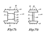
- Figure 7 shows two embodiments of the multi-chamber jamb 24 in detail, whereby in figures 7A and 7B , the multi-chamber jamb 24 is provided with a narrower or a wider base part 28 respectively, and thus is more appropriate to be applied in a narrower or wider composed jamb respectively.
- the base part 28 of the multi-chamber jamb 24 from figure 7A also differs from the variant in figure 7B in that there are two cross partitions 29 so as to form three chambers 30 preventing the cold flow in the composed jamb 1 and so as to additionally guarantee the geometry being maintained after the clamping.
- the method for insulating a jamb 1 for exterior joinery work is very simple and as follows.
- the multi-chamber jamb 24 and the thermally insulating strips 4-5 are pre-assembled and put together between the inner and the outer scale 2-3, whereby the multi-chamber jamb 24 is being held between the insulating strips 4-5 by the ribs 12 as the ribs 12 mesh in the multi-chamber jamb 24.
- the strips 4-5 are thereby provided with their free edges 11 in the grooves 8, whereas the multi-chamber jamb 24 will be automatically centred in the conical groove 27 thanks to the conical crosscut flanges 25, the conical flanges 25 thus forming centring means.
- the insulating strips 4-5 are fixed with their longitudinal edges 11 to the scales 2-3 by rolling in, for example, whereby the outer ribs 9 of the inner and outer scale 2-3 are transformed towards the inside so as to clamp or frame the above-mentioned free edges 11 of the insulating strips 4-5.
- the multi-chamber jamb 24 is thereby preferably clamped in the axial direction between the walls 6-7 of the inner and outer scale 2-3, whereby the ribs 26 serve as clamping means.
- the slanting erection of said distance ribs 26 in relation to the flanges 25 and to the inner scale and the outer scale serves to compensate for dimensional tolerances when clamping the multi-chamber jamb 24, such that said multi-chamber jamb 24 is always sufficiently clamped, which is absolutely necessary for a smooth processing of the window or door jamb during the later production process, for example as the multi-chamber jamb might shift while the jamb 1 is being processed.
- the cross section of figure 8 differs from that in figure 6 in that the jamb 1 is not so wide and is provided with the I-shaped multi-chamber jamb 24 from figure 7B .
- the cross ribs 12 on the strips 4-5 which are directed towards the base part 28 of the multi-chamber jamb 24 form entirely separated compartments 13 in the space between the outer and inner scale 2-3, preventing any cold flow from the outer to the inner scale.
- cross ribs 12 create a zigzag structure on the strips 4-5 in the space which is confined between the multi-chamber jamb 24, the insulating strip 4-5 and the inner and outer scales 2-3.
- outward protruding elements and ribs may vary as a function of the required application.
Landscapes
- Engineering & Computer Science (AREA)
- Civil Engineering (AREA)
- Structural Engineering (AREA)
- Physics & Mathematics (AREA)
- Thermal Sciences (AREA)
- Wing Frames And Configurations (AREA)
Description
- The present invention concerns a method for insulating a jamb for exterior joinery work such as doors, windows or the like.
- It is known that door or window jambs are formed of two jambs, i.e. what are called the outer scale and inner scale, usually made of aluminium, and at least two thermally insulating strips in the shape of jambs provided at a distance from one another between the outer scale and the inner scale so as to form a thermal interruption, whereby said strips are fixed in grooves of the outer scale and of the inner scale with their longitudinal edges during the assembly of the door or window jamb.
- The strips are usually clamped in the grooves by what is called the roll-in technique, whereby the outer edges of the aforesaid grooves are plastically transformed by folding down said edges towards the inside by means of a roller or the like.
- A good thermal interruption makes sure that there is not any cold radiation from the outer scale to the inner scale.
- This is obtained among others by dividing the space between the strips and the outer and inner scale in air compartments that are separated from one another by means of crosswise directed partitions.
- Such thermal interruptions usually have a very complex shape and, consequently, are very expensive.
- Moreover, the shape and dimensions of such thermal interruptions are usually focussed on a single type of window or door jamb and, consequently, they cannot be universally applied, which also makes their application expensive.
- Solutions are already known whereby foam strips are additionally provided between the thermally insulating strips, which foam strips are pushed in the cavity between said strips in their longitudinal direction.
- This assembly method restricts the length of the jambs, however, for example to a length of 6 meters.
- Moreover, techniques are known for injecting insulating material between the thermally insulating strips, which is a complex and expensive process, however.
-
DE 35 45 092 A1 shows a known method for insulating a jamb according to the preamble of claim 1 and a known insulated jamb according to the preamble ofclaim 3. - The invention aims to remedy one or several of the above-mentioned disadvantages and to obtain considerable insulating values for the thermal interruption of aluminium systems for manufacturing exterior joinery work in a simple and cheap manner.
- To this end, the invention concerns a method for insulating a jamb for exterior joinery work of the above-mentioned type, according to claim 1.
- As a function of the width of the thermal bridge, it is possible to create several compartments, thanks to a combination of the above-mentioned strips and multi-chamber jambs, which can efficiently restrict the cold transfer from the outside to the inside.
- Thus, a limited series of strip forms and multi-chamber jambs can provide for an efficient thermal insulation for several types and forms of window and door jambs, with a restricted supply of said elements.
- Thanks to said limited series of forms, less extrusion dies will have to be provided for to manufacture the strips and multi-chamber jambs than has been the case up to now, resulting in lower production costs.
- The basic form of the strips is preferably the conventional Omega structure.
- The cross ribs thereby serve as partitions which stop the cold radiation.
- The I-shaped multi-chamber jamb between the strips, together with the ribs of the strips, form compartments which have a positive effect on the insulating value of the jambs.
- The special design of the multi-chamber jambs has been conceived such that a mechanical insert is possible before the strips are assembled between an aluminium outer scale and inner scale.
- The I-shape provides the multi-chamber jamb with a strong and robust design which resists any transformation of the jamb.
- The multi-chamber jambs are profiled such that, after the assembly of the window or door jamb, they are kept in place in a clamping manner between the outer scale and inner scale by means of conical clamping as well as by means of slantingly provided distance ribs.
- This offers an additional advantage in that the strips of the thermal interruption and the multi-chamber jamb can be assembled as a whole with the aluminium inner and outer scale, and in that they can be subsequently assembled in a single operation by means of a conventional strip roll-in machine or tool.
- The present invention also concerns an insulated jamb for exterior joinery work such as a door or window jamb or the like, according to
claim 3. - In order to better explain the characteristics of the invention, the following preferred applications of the method for insulating an outer jamb for exterior joinery work and an insulated jamb according to the invention are described by way of example only, without being limitative in any way, with reference to the accompanying drawings, in which:
-
figure 1 schematically represents a jamb for exterior joinery work, seen as a section but not according to the invention; -
figures 2A to 2D represent possible strip forms that can be selected to modularly compose a jamb for exterior joinery work in accordance with the invention; -
figure 3 represents a jamb not according to the invention as infigure 1 , but applied in a wider jamb; -
figure 4 represents a jamb not according to the invention in which the strips offigures 2C and 2D have been combined so as to form a thermal insulation; -
figure 5 represents exterior joinery work with a fixed frame and a hinge-mounted leaf, composed of insulated jambs not according to the invention; -
figure 6 represents a jamb which is insulated according to the method of the invention, making use of insulation strips that are selected from the series offigures 2A to 2D , combined with an I-shaped multi-chamber jamb, provided with two conical crosscut ends with several slantingly provided distance ribs; -
figure 7A shows a detail of the multi-chamber jamb which is indicated by F7A infigure 6 ; -
figure 7B shows a variant offigure 7A for a narrower jamb as represented infigure 8 ; -
figure 8 shows a jamb which is analogous to the embodiment offigure 6 , but with a smaller jamb section. -
Figure 1 schematically shows a jamb 1 of the exterior joinery work of a window, a door or the like, whereby the jamb 1 is in this case composed of two parallel jambs 2-3 made of aluminium or another material, i.e. anouter scale 2 and aninner scale 3 respectively, which are connected to one another by means of two thermally insulating strips 4-5 made of a heat-insulating material, for example a synthetic material or a composite material. - On the walls 6-7 of the scales 2-3 directed towards one another are provided
grooves 8 for every insulating strip 4-5 which are situated opposite one another in this case, but which is not necessarily so. - The
grooves 8 are defined byribs 9 provided crosswise on the above-mentioned walls 6-7 at a distance from one another. - In the given embodiment, the insulating strips 4-5 have the conventional Omega structure, forming the
base part 10 of the strip, and whereby thelongitudinal edges 11 of the Omega widen so as to fix thelongitudinal edges 11 in thegrooves 8 of the inner and outer scale 2-3. - One or
several cross ribs 12 can be provided on thebase part 10. - In the given jamb 1 of
figure 1 , the strips 4-5 have one and twocross ribs 12 respectively which are directed towards one another, such that thecross ribs 12 divide the space between the inner and outer scale in four crosswise directedcompartments 13 which are separated from one another and thus prevent any cold flow. - The method for insulating and assembling a jamb as that of
figure 1 , consisting of an outer and an inner scale, is very simple and as follows. - From a limited series of strip forms is selected a combination of
insulating strips selected strips longitudinal edges 11 in thegrooves 8 of the inner andouter scale - The presence of the
cross ribs 12 on thebase part 10 of bothinsulating strips compartments 13 and improves the insulating qualities of the obtained jamb 1. -
Figures 2A-2D show some practical embodiments of a limited series of insulating strips in detail. - The
insulating strip 14 infigure 2A is provided with twoparallel cross ribs 12 on the inside and it is provided with astop part 15 on the outside which, together with thebase part 10, encloses a space, whereby thisstop part 15, after the assembly of the jamb 1, can serve as a stop to a hinge element, for example. - In the variant of
figure 2B , thebase part 10 of theinsulating strip 4 is provided with across rib 12 on one side situated around the centre of theaforesaid base part 10. - The
insulating strip 5 offigure 2C is provided with a T-shaped element 16 on the outside of thebase part 10, such that in an assembled jamb 1, a sealing material, a sealing jamb or the like can be fixed to said T-shaped element 16. -
Figure 2D represents aninsulating strip 17 which is a simplified version of the strip fromfigure 2C , whereby thecross ribs 12 have been omitted and only a T-shaped element 16 is provided on the outer perimeter of thebase part 10. - It is clear that the jamb 1 represented in
figure 1 of the strips 4-5 fromfigures 2B and 2C has been provided and that it is easy to build the window or door jamb in a modular manner, as a function of the required window or door jamb, with an appropriate selection of insulating strips selected from the limited series represented infigures 2A to 2D . - It will be clear to the craftsman that the above-described method is not restricted to the above-mentioned combination of strips in the jamb.
- The jamb from
figure 3 differs from that infigure 1 in that the outer and inner scales 2-3 are made wider. - As the
grooves 8 in which theinsulating strips compartments 13 formed in the space between the scales are not entirely separated; on the contrary, the insulating strips create a zigzag structure in the space, and in this way as well cold flow is prevented. -
Figure 4 shows a cross section of a jamb 1 in which theinsulating strips figures 2C and 2D connect the outer and inner scale 2-3 to one another. - Thanks to the position of the
grooves 8 on the walls 6-7 of the scales 2-3 which are directed towards one another, thecross ribs 12 of the insulating strips formseparate compartments 13 in the space between the outer and inner scale 2-3. -
Figure 5 shows a cross section of joinery comprising thejamb 18 of a fixed frame and thejamb 19 of the rotating leaf of a window or door working in conjunction with the latter. - The connection between the
fixed jamb 18 and theleaf 19 is realised by means of a hinge element, not represented in the figures. - The fixed
jamb 18 is provided with the insulating strips 4-5 fromfigures 2B and 2C . - At the far end of the
wall 6 of theouter jamb 2 is provided a sealingjamb 20, provided on a standingedge 21. - The standing
edge 21 is situated at thehead 22 of the T-shaped element 16, such that the T-shaped element 16 and the standingedge 21 form a slot in between which ahead 23 of the sealingjamb 20 can be provided in a clamping manner. - The
jamb 19 of the leaf is provided with theinsulating strip 14 fromfigure 2A , whereby thestop part 15 functions as a stop to the sealingjamb 20. -
Figure 6 shows an embodiment according to the invention of a wide jamb 1 whereby the use of two insulating strips is combined with an I-shapedmulti-chamber jamb 24. - In the given embodiment, the
multi-chamber jamb 24 is provided with twoparallel flanges 25, narrowing in a conical manner, and on which are provided one orseveral ribs 26 extending in the longitudinal direction on the sides of theflanges 25 directed towards the scales 2-3, and with which themulti-chamber jamb 24 is provided in aconical groove 27 on the walls 6-7 of the scales 2-3 directed towards one another in a clamping manner. - The
grooves 27 are preferably confined by theinner ribs 9 of thegrooves 8. - In the given embodiment, the
multi-chamber jamb 24 is provided between the insulating strips 4-5, and thecross ribs 12 on the strips 4-5 are directed towards saidmulti-chamber jamb 24, such thatseveral compartments 13 are formed in the space between the strips 4-5 and themulti-chamber jamb 24, as a result of which an even better insulating value of the composed jamb 1 is obtained. - The multi-chamber jamb has been especially made I-shaped in order to guarantee its rigidity and so as to maintain its geometry after its clamping.
- The
multi-chamber jamb 24 can be made of a synthetic material, but of course the use of other insulating materials is not excluded according to the invention. -
Figure 7 shows two embodiments of themulti-chamber jamb 24 in detail, whereby infigures 7A and 7B , themulti-chamber jamb 24 is provided with a narrower or awider base part 28 respectively, and thus is more appropriate to be applied in a narrower or wider composed jamb respectively. - The
base part 28 of themulti-chamber jamb 24 fromfigure 7A also differs from the variant infigure 7B in that there are twocross partitions 29 so as to form threechambers 30 preventing the cold flow in the composed jamb 1 and so as to additionally guarantee the geometry being maintained after the clamping. - Naturally, the invention is not restricted to such
multi-chamber jambs 24 with threechambers 30, and alternative embodiments with more or lesscross partitions 29 are possible as well. - The method for insulating a jamb 1 for exterior joinery work is very simple and as follows.
- First, the
multi-chamber jamb 24 and the thermally insulating strips 4-5 are pre-assembled and put together between the inner and the outer scale 2-3, whereby themulti-chamber jamb 24 is being held between the insulating strips 4-5 by theribs 12 as theribs 12 mesh in themulti-chamber jamb 24. - The strips 4-5 are thereby provided with their
free edges 11 in thegrooves 8, whereas themulti-chamber jamb 24 will be automatically centred in theconical groove 27 thanks to the conicalcrosscut flanges 25, theconical flanges 25 thus forming centring means. - Next, the insulating strips 4-5 are fixed with their
longitudinal edges 11 to the scales 2-3 by rolling in, for example, whereby theouter ribs 9 of the inner and outer scale 2-3 are transformed towards the inside so as to clamp or frame the above-mentionedfree edges 11 of the insulating strips 4-5. - The
multi-chamber jamb 24 is thereby preferably clamped in the axial direction between the walls 6-7 of the inner and outer scale 2-3, whereby theribs 26 serve as clamping means. The slanting erection of saiddistance ribs 26 in relation to theflanges 25 and to the inner scale and the outer scale serves to compensate for dimensional tolerances when clamping themulti-chamber jamb 24, such that said multi-chamber jamb 24 is always sufficiently clamped, which is absolutely necessary for a smooth processing of the window or door jamb during the later production process, for example as the multi-chamber jamb might shift while the jamb 1 is being processed. - The cross section of
figure 8 differs from that infigure 6 in that the jamb 1 is not so wide and is provided with the I-shaped multi-chamber jamb 24 fromfigure 7B . - The
cross ribs 12 on the strips 4-5 which are directed towards thebase part 28 of themulti-chamber jamb 24 form entirely separatedcompartments 13 in the space between the outer and inner scale 2-3, preventing any cold flow from the outer to the inner scale. - Naturally, alternative embodiments are possible whereby the
cross ribs 12 create a zigzag structure on the strips 4-5 in the space which is confined between themulti-chamber jamb 24, the insulating strip 4-5 and the inner and outer scales 2-3. - It is clear that the series of strip forms and multi-chamber jambs is not necessarily limited to those represented in the figures, but that for example also more than two cross ribs can be provided on the insulating strips and that the width of the multi-chamber jambs is not necessarily restricted to both embodiments of
figures 7A and 7B . - Also the outward protruding elements and ribs may vary as a function of the required application.
- It is clear that, thanks to the modular composition of the jambs, many possibilities are created to efficiently insulate many possible jamb forms by making a selection from a series of insulating strips and multi-chamber jambs.
- The present invention is by no means restricted to the embodiments of jambs given by way of example and represented in the accompanying drawings; on the contrary, such a method and jambs can be made according to different variants while still remaining within the scope of the invention as defined by the claims.
Claims (11)
- Method for insulating a jamb (1) for exterior joinery work such as a door or window jamb, formed of two jambs (2-3), what are called an outer scale (2) and inner scale (3), and at least two thermally insulating strips (4,5) in the shape of jambs provided at a distance from one another between the outer scale (2) and the inner scale (3) so as to form a thermal interruption, whereby these strips (4-5) are clamped in grooves (8) of the outer scale (2) and of the inner scale (3) with their longitudinal edges (11) during the assembly of the door or window jamb (1) by rolling in, whereby the door or window jamb (1) is modular, making use of a combination of insulating strips (4-5) selected from a limited series of strip forms with predominantly similar-shaped base parts (10) so as to connect the outer scale (2) and the inner scale (3), which combination of insulating strips (4-5) is applied in combination with at least one I-shaped jamb (24), made of insulating material, provided with its parallel flanges clamped between the inner scale and outer scale, and which is selected from a limited series of I-shaped jambs (24) having different widths, characterised in that the insulating strips are provided with one or several cross ribs (12) on said base parts (10), in that said I-shaped jamb is a multi-chamber I-shaped jamb (24), provided with its core between the cross ribs (12) of the insulating strips (4-5) with said core directed crosswise to the aforesaid cross ribs (12) and whereby, thanks to the mutual combination of the insulating strips (4-5) with at least one I-shaped multi-chamber jamb (24), the space between the insulating strips (4-5) and the I-shaped multi-chamber jamb (24) is divided in crosswise directed compartments (13).
- Method according to claim 1, characterised in that the strips (4-5) of the thermal interruption and the I-shaped multi-chamber jamb (24) are assembled as a whole and are provided as a whole between the inner and outer scale, and subsequently are fixed to the inner scale and outer scale by clamping the longitudinal edges of the strips (4-5) in the grooves (8) of the inner scale or outer scale by rolling them in or the like.
- Insulated jamb (1) for exterior joinery work such as a door, a window jamb or the like, said jamb (1) being is modularly built and comprises at least two jambs (2-3), what are called an outer scale (2) and an inner scale (3), and at least two thermally insulating strips (4-5) on the one hand, whereby the above-mentioned insulating strips (4-5) are provided at a distance from one another between the outer scale (2) and the inner scale (3) so as to form a thermal interruption, whereby the insulating strips (4-5) comprise base parts (10) and, on the other hand, at least one I-shaped jamb (24) provided with its core between the insulating strips (4-5), and which is clamped with its parallel flanges between the inner scale and the outer scale, characterised in that the insulating strips are provided with one or several cross ribs (12) on said base parts (10), in that said I-shaped jamb is a multi-chamber I-shaped jamb (24), with its core directed crosswise to the aforesaid cross ribs (12) and whereby, thanks to the mutual combination of the insulating strips (4-5) with the at least one I-shaped multi-chamber jamb (24), the space between the insulating strips (4-5) and the I-shaped multi-chamber jamb (24) is divided in crosswise directed compartments (13).
- Insulated jamb (1) according to claim 3, characterised in that the multi-chamber jamb (24) is provided with clamping means.
- Insulated jamb (1) according to claim 4, characterised in that the above-mentioned clamping means consist of one or several ribs (26) extending in the longitudinal direction on the sides of the flanges of the I-shaped multi-chamber jamb (24) directed towards the inner scale and outer scale.
- Insulated jamb (1) according to claim 4 or 5, characterised in that the aforesaid ribs are provided slantingly on the aforesaid sides of the flanges of the I-shaped multi-chamber jamb (24) directed towards the inner scale and outer scale.
- Insulated jamb (1) according to any of claims 4 to 6, characterised in that the aforesaid ribs are placed symmetrically in relation to the plane of symmetry of the I-shaped multi-chamber jamb (24).
- Insulated jamb (1) according to any of claims 3 to 7, characterised in that the multi-chamber jamb (24) is provided with centring means.
- Insulated jamb (1) according to claim 8, characterised in that the centring means are formed by making the flanges (25) of the multi-chamber jamb (24) conical so as to cooperate with a conical groove (27) of the scales (2-3).
- Insulated jamb (1) according to claims 7 and 9, characterised in that the centring means are formed of the outer ribs on each flange of the I-shaped multi-chamber jamb (24).
- Insulated jamb (1) according to any one of claims 3 to 10, characterised in that the multi-chamber jamb (24) is provided with cross partitions (29) so as to form one or several chambers (30).
Priority Applications (1)
| Application Number | Priority Date | Filing Date | Title |
|---|---|---|---|
| PL09007045T PL2128371T3 (en) | 2008-05-28 | 2009-05-27 | Method for insulating a jamb for exterior joinery work |
Applications Claiming Priority (2)
| Application Number | Priority Date | Filing Date | Title |
|---|---|---|---|
| BE200800296A BE1018163A6 (en) | 2008-05-28 | 2008-05-28 | Insulating method of jamb for exterior joinery work e.g. door or window jamb involves dividing space between strips and L-shaped multi-chamber jamb in cross-wise directed compartments |
| BE2008/0488A BE1018277A3 (en) | 2008-05-28 | 2008-09-03 | METHOD FOR ISOLATING A PROFILE FOR AN OUTSIDE WORK. |
Publications (2)
| Publication Number | Publication Date |
|---|---|
| EP2128371A1 EP2128371A1 (en) | 2009-12-02 |
| EP2128371B1 true EP2128371B1 (en) | 2013-02-13 |
Family
ID=40940632
Family Applications (1)
| Application Number | Title | Priority Date | Filing Date |
|---|---|---|---|
| EP09007045A Active EP2128371B1 (en) | 2008-05-28 | 2009-05-27 | Method for insulating a jamb for exterior joinery work |
Country Status (2)
| Country | Link |
|---|---|
| EP (1) | EP2128371B1 (en) |
| PL (1) | PL2128371T3 (en) |
Cited By (2)
| Publication number | Priority date | Publication date | Assignee | Title |
|---|---|---|---|---|
| CN103758440A (en) * | 2013-12-25 | 2014-04-30 | 泰诺风保泰(苏州)隔热材料有限公司 | Multi-cavity thermal insulation bar |
| EP3339550A1 (en) | 2016-12-20 | 2018-06-27 | Blyweert Aluminium SP. z.o.o. | Aluminium carpentry system having improved thermal insulation |
Families Citing this family (2)
| Publication number | Priority date | Publication date | Assignee | Title |
|---|---|---|---|---|
| CN107165541B (en) * | 2017-07-12 | 2019-01-08 | 天鹅铝业有限公司 | A kind of heat insulation type door and window aluminium alloy extrusions |
| CN113175287A (en) * | 2021-05-12 | 2021-07-27 | 山东闼闼久禾门窗科技有限公司 | Section bar with built-in sound insulation bar grating type heat insulation bar and energy-saving bridge-cut-off aluminum alloy window |
Family Cites Families (7)
| Publication number | Priority date | Publication date | Assignee | Title |
|---|---|---|---|---|
| DE3221218A1 (en) * | 1982-06-04 | 1983-12-08 | Helmar Dr.Dr. 8530 Neustadt Nahr | Profiled body |
| DE3545092A1 (en) * | 1985-10-17 | 1987-04-30 | Gartner & Co J | Composite profile |
| DE4203760C2 (en) * | 1992-02-10 | 1995-08-24 | Wilfried Ensinger | Composite profile |
| DE29723853U1 (en) * | 1996-09-30 | 1999-09-02 | W. Hartmann & Co (Gmbh & Co), 20459 Hamburg | Insulated composite profile |
| EP0906999B2 (en) * | 1997-10-04 | 2008-05-28 | Albert Krämer | Insulating web for composite profiles of window or door frames |
| EP0957226A1 (en) * | 1998-05-14 | 1999-11-17 | Technoform Caprano + Brunnhofer oHG | Compound section member for doors, windows, facades or the like, IR-reflective film especially adapted for this section member and the use of this film in the compound section member |
| CZ14844U1 (en) * | 2004-07-02 | 2004-10-25 | Čechoplast, Spol. S R. O. | Insulation cage |
-
2009
- 2009-05-27 EP EP09007045A patent/EP2128371B1/en active Active
- 2009-05-27 PL PL09007045T patent/PL2128371T3/en unknown
Cited By (3)
| Publication number | Priority date | Publication date | Assignee | Title |
|---|---|---|---|---|
| CN103758440A (en) * | 2013-12-25 | 2014-04-30 | 泰诺风保泰(苏州)隔热材料有限公司 | Multi-cavity thermal insulation bar |
| CN103758440B (en) * | 2013-12-25 | 2016-05-04 | 泰诺风保泰(苏州)隔热材料有限公司 | A kind of Multicarity heat insulating strip |
| EP3339550A1 (en) | 2016-12-20 | 2018-06-27 | Blyweert Aluminium SP. z.o.o. | Aluminium carpentry system having improved thermal insulation |
Also Published As
| Publication number | Publication date |
|---|---|
| PL2128371T3 (en) | 2013-09-30 |
| EP2128371A1 (en) | 2009-12-02 |
Similar Documents
| Publication | Publication Date | Title |
|---|---|---|
| US8286396B2 (en) | Plastic profile for window, door and facade elements | |
| EP2278108B1 (en) | Insulated frame member | |
| US8828171B2 (en) | Use of a fibre-reinforced plastic material as a reinforcement system of a profile for a window or door frame | |
| EP3084109B2 (en) | Plastic insulating course, composite profile and window that comprise such an insulating course and method for producing a frame for a window | |
| EP3256679B1 (en) | Sash for a sliding window or a sliding door and method for providing an untreated metal surface in such a sash | |
| HU219277B (en) | Frame member for a switchgear cabinet frame | |
| CA2377862A1 (en) | Hollow plastic section | |
| EP2128371A1 (en) | Method for insulating a jamb for exterior joinery work | |
| EP3447229A1 (en) | Thermally insulated composite profile | |
| CN101573505A (en) | Molded fiberglass sidelite assembly | |
| EP1234945B1 (en) | Window and door frames | |
| EP2864567A1 (en) | Insulating web for a compound profile for windows, doors or façade elements, and method for production of such an insulating web and compound profile having such an insulating web | |
| KR20190022179A (en) | Sliding frame having multi chamber and window having the same | |
| HU216266B (en) | Profile frame strip and method for producing it, as well as frame construction for insulating glazing and spacer | |
| KR101767089B1 (en) | Prefabricated insulated stainless steel windows frames | |
| GB2434395A (en) | Frame member with insulating portion | |
| KR101765548B1 (en) | the zigzag assembly type structure of insulation window frames as well as window and doors | |
| HU226439B1 (en) | Construction element and use of a support, and method for the production of an element for a facade | |
| KR101930473B1 (en) | the structure of stainless steel insulation window frame | |
| CN102808566A (en) | Four-seal aluminum plastic and aluminum composite energy-saving door and window structure | |
| KR102814466B1 (en) | Insulating materials with improved insulation properties and insulated doors using them | |
| EP3507442B1 (en) | Structural element for installation of doors and windows | |
| KR20210068167A (en) | Complex partition frame structure for both single and dual panels | |
| CN111119667B (en) | Cover assembly for door and window false middle stile and door and window assembly | |
| EP3974165B1 (en) | An arch former |
Legal Events
| Date | Code | Title | Description |
|---|---|---|---|
| PUAI | Public reference made under article 153(3) epc to a published international application that has entered the european phase |
Free format text: ORIGINAL CODE: 0009012 |
|
| AK | Designated contracting states |
Kind code of ref document: A1 Designated state(s): AT BE BG CH CY CZ DE DK EE ES FI FR GB GR HR HU IE IS IT LI LT LU LV MC MK MT NL NO PL PT RO SE SI SK TR |
|
| 17P | Request for examination filed |
Effective date: 20100420 |
|
| 17Q | First examination report despatched |
Effective date: 20100624 |
|
| GRAP | Despatch of communication of intention to grant a patent |
Free format text: ORIGINAL CODE: EPIDOSNIGR1 |
|
| GRAS | Grant fee paid |
Free format text: ORIGINAL CODE: EPIDOSNIGR3 |
|
| GRAA | (expected) grant |
Free format text: ORIGINAL CODE: 0009210 |
|
| AK | Designated contracting states |
Kind code of ref document: B1 Designated state(s): AT BE BG CH CY CZ DE DK EE ES FI FR GB GR HR HU IE IS IT LI LT LU LV MC MK MT NL NO PL PT RO SE SI SK TR |
|
| REG | Reference to a national code |
Ref country code: GB Ref legal event code: FG4D |
|
| REG | Reference to a national code |
Ref country code: AT Ref legal event code: REF Ref document number: 596605 Country of ref document: AT Kind code of ref document: T Effective date: 20130215 |
|
| REG | Reference to a national code |
Ref country code: IE Ref legal event code: FG4D |
|
| REG | Reference to a national code |
Ref country code: DE Ref legal event code: R096 Ref document number: 602009013179 Country of ref document: DE Effective date: 20130411 |
|
| REG | Reference to a national code |
Ref country code: AT Ref legal event code: MK05 Ref document number: 596605 Country of ref document: AT Kind code of ref document: T Effective date: 20130213 |
|
| REG | Reference to a national code |
Ref country code: NL Ref legal event code: VDEP Effective date: 20130213 |
|
| REG | Reference to a national code |
Ref country code: LT Ref legal event code: MG4D |
|
| PG25 | Lapsed in a contracting state [announced via postgrant information from national office to epo] |
Ref country code: NO Free format text: LAPSE BECAUSE OF FAILURE TO SUBMIT A TRANSLATION OF THE DESCRIPTION OR TO PAY THE FEE WITHIN THE PRESCRIBED TIME-LIMIT Effective date: 20130513 Ref country code: LT Free format text: LAPSE BECAUSE OF FAILURE TO SUBMIT A TRANSLATION OF THE DESCRIPTION OR TO PAY THE FEE WITHIN THE PRESCRIBED TIME-LIMIT Effective date: 20130213 Ref country code: AT Free format text: LAPSE BECAUSE OF FAILURE TO SUBMIT A TRANSLATION OF THE DESCRIPTION OR TO PAY THE FEE WITHIN THE PRESCRIBED TIME-LIMIT Effective date: 20130213 Ref country code: BG Free format text: LAPSE BECAUSE OF FAILURE TO SUBMIT A TRANSLATION OF THE DESCRIPTION OR TO PAY THE FEE WITHIN THE PRESCRIBED TIME-LIMIT Effective date: 20130513 Ref country code: IS Free format text: LAPSE BECAUSE OF FAILURE TO SUBMIT A TRANSLATION OF THE DESCRIPTION OR TO PAY THE FEE WITHIN THE PRESCRIBED TIME-LIMIT Effective date: 20130613 Ref country code: SE Free format text: LAPSE BECAUSE OF FAILURE TO SUBMIT A TRANSLATION OF THE DESCRIPTION OR TO PAY THE FEE WITHIN THE PRESCRIBED TIME-LIMIT Effective date: 20130213 Ref country code: ES Free format text: LAPSE BECAUSE OF FAILURE TO SUBMIT A TRANSLATION OF THE DESCRIPTION OR TO PAY THE FEE WITHIN THE PRESCRIBED TIME-LIMIT Effective date: 20130524 |
|
| PG25 | Lapsed in a contracting state [announced via postgrant information from national office to epo] |
Ref country code: LV Free format text: LAPSE BECAUSE OF FAILURE TO SUBMIT A TRANSLATION OF THE DESCRIPTION OR TO PAY THE FEE WITHIN THE PRESCRIBED TIME-LIMIT Effective date: 20130213 Ref country code: PT Free format text: LAPSE BECAUSE OF FAILURE TO SUBMIT A TRANSLATION OF THE DESCRIPTION OR TO PAY THE FEE WITHIN THE PRESCRIBED TIME-LIMIT Effective date: 20130613 Ref country code: GR Free format text: LAPSE BECAUSE OF FAILURE TO SUBMIT A TRANSLATION OF THE DESCRIPTION OR TO PAY THE FEE WITHIN THE PRESCRIBED TIME-LIMIT Effective date: 20130514 Ref country code: BE Free format text: LAPSE BECAUSE OF FAILURE TO SUBMIT A TRANSLATION OF THE DESCRIPTION OR TO PAY THE FEE WITHIN THE PRESCRIBED TIME-LIMIT Effective date: 20130213 Ref country code: FI Free format text: LAPSE BECAUSE OF FAILURE TO SUBMIT A TRANSLATION OF THE DESCRIPTION OR TO PAY THE FEE WITHIN THE PRESCRIBED TIME-LIMIT Effective date: 20130213 Ref country code: SI Free format text: LAPSE BECAUSE OF FAILURE TO SUBMIT A TRANSLATION OF THE DESCRIPTION OR TO PAY THE FEE WITHIN THE PRESCRIBED TIME-LIMIT Effective date: 20130213 |
|
| PG25 | Lapsed in a contracting state [announced via postgrant information from national office to epo] |
Ref country code: HR Free format text: LAPSE BECAUSE OF FAILURE TO SUBMIT A TRANSLATION OF THE DESCRIPTION OR TO PAY THE FEE WITHIN THE PRESCRIBED TIME-LIMIT Effective date: 20130213 |
|
| REG | Reference to a national code |
Ref country code: PL Ref legal event code: T3 |
|
| PG25 | Lapsed in a contracting state [announced via postgrant information from national office to epo] |
Ref country code: DK Free format text: LAPSE BECAUSE OF FAILURE TO SUBMIT A TRANSLATION OF THE DESCRIPTION OR TO PAY THE FEE WITHIN THE PRESCRIBED TIME-LIMIT Effective date: 20130213 Ref country code: SK Free format text: LAPSE BECAUSE OF FAILURE TO SUBMIT A TRANSLATION OF THE DESCRIPTION OR TO PAY THE FEE WITHIN THE PRESCRIBED TIME-LIMIT Effective date: 20130213 Ref country code: CZ Free format text: LAPSE BECAUSE OF FAILURE TO SUBMIT A TRANSLATION OF THE DESCRIPTION OR TO PAY THE FEE WITHIN THE PRESCRIBED TIME-LIMIT Effective date: 20130213 Ref country code: EE Free format text: LAPSE BECAUSE OF FAILURE TO SUBMIT A TRANSLATION OF THE DESCRIPTION OR TO PAY THE FEE WITHIN THE PRESCRIBED TIME-LIMIT Effective date: 20130213 Ref country code: NL Free format text: LAPSE BECAUSE OF FAILURE TO SUBMIT A TRANSLATION OF THE DESCRIPTION OR TO PAY THE FEE WITHIN THE PRESCRIBED TIME-LIMIT Effective date: 20130213 Ref country code: RO Free format text: LAPSE BECAUSE OF FAILURE TO SUBMIT A TRANSLATION OF THE DESCRIPTION OR TO PAY THE FEE WITHIN THE PRESCRIBED TIME-LIMIT Effective date: 20130213 |
|
| PLBE | No opposition filed within time limit |
Free format text: ORIGINAL CODE: 0009261 |
|
| STAA | Information on the status of an ep patent application or granted ep patent |
Free format text: STATUS: NO OPPOSITION FILED WITHIN TIME LIMIT |
|
| PG25 | Lapsed in a contracting state [announced via postgrant information from national office to epo] |
Ref country code: IT Free format text: LAPSE BECAUSE OF FAILURE TO SUBMIT A TRANSLATION OF THE DESCRIPTION OR TO PAY THE FEE WITHIN THE PRESCRIBED TIME-LIMIT Effective date: 20130213 Ref country code: MC Free format text: LAPSE BECAUSE OF FAILURE TO SUBMIT A TRANSLATION OF THE DESCRIPTION OR TO PAY THE FEE WITHIN THE PRESCRIBED TIME-LIMIT Effective date: 20130213 |
|
| REG | Reference to a national code |
Ref country code: CH Ref legal event code: PL |
|
| 26N | No opposition filed |
Effective date: 20131114 |
|
| GBPC | Gb: european patent ceased through non-payment of renewal fee |
Effective date: 20130527 |
|
| PG25 | Lapsed in a contracting state [announced via postgrant information from national office to epo] |
Ref country code: DE Free format text: LAPSE BECAUSE OF NON-PAYMENT OF DUE FEES Effective date: 20131203 Ref country code: CH Free format text: LAPSE BECAUSE OF NON-PAYMENT OF DUE FEES Effective date: 20130531 Ref country code: LI Free format text: LAPSE BECAUSE OF NON-PAYMENT OF DUE FEES Effective date: 20130531 |
|
| REG | Reference to a national code |
Ref country code: DE Ref legal event code: R097 Ref document number: 602009013179 Country of ref document: DE Effective date: 20131114 |
|
| REG | Reference to a national code |
Ref country code: IE Ref legal event code: MM4A |
|
| REG | Reference to a national code |
Ref country code: DE Ref legal event code: R119 Ref document number: 602009013179 Country of ref document: DE Effective date: 20131203 |
|
| REG | Reference to a national code |
Ref country code: FR Ref legal event code: ST Effective date: 20140131 |
|
| PG25 | Lapsed in a contracting state [announced via postgrant information from national office to epo] |
Ref country code: IE Free format text: LAPSE BECAUSE OF NON-PAYMENT OF DUE FEES Effective date: 20130527 Ref country code: GB Free format text: LAPSE BECAUSE OF NON-PAYMENT OF DUE FEES Effective date: 20130527 |
|
| PG25 | Lapsed in a contracting state [announced via postgrant information from national office to epo] |
Ref country code: FR Free format text: LAPSE BECAUSE OF NON-PAYMENT OF DUE FEES Effective date: 20130531 |
|
| PG25 | Lapsed in a contracting state [announced via postgrant information from national office to epo] |
Ref country code: MT Free format text: LAPSE BECAUSE OF FAILURE TO SUBMIT A TRANSLATION OF THE DESCRIPTION OR TO PAY THE FEE WITHIN THE PRESCRIBED TIME-LIMIT Effective date: 20130213 |
|
| PG25 | Lapsed in a contracting state [announced via postgrant information from national office to epo] |
Ref country code: TR Free format text: LAPSE BECAUSE OF FAILURE TO SUBMIT A TRANSLATION OF THE DESCRIPTION OR TO PAY THE FEE WITHIN THE PRESCRIBED TIME-LIMIT Effective date: 20130213 Ref country code: CY Free format text: LAPSE BECAUSE OF FAILURE TO SUBMIT A TRANSLATION OF THE DESCRIPTION OR TO PAY THE FEE WITHIN THE PRESCRIBED TIME-LIMIT Effective date: 20130213 |
|
| PG25 | Lapsed in a contracting state [announced via postgrant information from national office to epo] |
Ref country code: MK Free format text: LAPSE BECAUSE OF FAILURE TO SUBMIT A TRANSLATION OF THE DESCRIPTION OR TO PAY THE FEE WITHIN THE PRESCRIBED TIME-LIMIT Effective date: 20130213 Ref country code: HU Free format text: LAPSE BECAUSE OF FAILURE TO SUBMIT A TRANSLATION OF THE DESCRIPTION OR TO PAY THE FEE WITHIN THE PRESCRIBED TIME-LIMIT; INVALID AB INITIO Effective date: 20090527 Ref country code: LU Free format text: LAPSE BECAUSE OF NON-PAYMENT OF DUE FEES Effective date: 20130527 |
|
| PGFP | Annual fee paid to national office [announced via postgrant information from national office to epo] |
Ref country code: PL Payment date: 20250214 Year of fee payment: 17 |