EP2128301A1 - Carburizing apparatus and carburizing method - Google Patents
Carburizing apparatus and carburizing method Download PDFInfo
- Publication number
- EP2128301A1 EP2128301A1 EP08711253A EP08711253A EP2128301A1 EP 2128301 A1 EP2128301 A1 EP 2128301A1 EP 08711253 A EP08711253 A EP 08711253A EP 08711253 A EP08711253 A EP 08711253A EP 2128301 A1 EP2128301 A1 EP 2128301A1
- Authority
- EP
- European Patent Office
- Prior art keywords
- carburizing
- gas
- light
- furnace
- furnace gas
- Prior art date
- Legal status (The legal status is an assumption and is not a legal conclusion. Google has not performed a legal analysis and makes no representation as to the accuracy of the status listed.)
- Withdrawn
Links
Images


Classifications
-
- C—CHEMISTRY; METALLURGY
- C23—COATING METALLIC MATERIAL; COATING MATERIAL WITH METALLIC MATERIAL; CHEMICAL SURFACE TREATMENT; DIFFUSION TREATMENT OF METALLIC MATERIAL; COATING BY VACUUM EVAPORATION, BY SPUTTERING, BY ION IMPLANTATION OR BY CHEMICAL VAPOUR DEPOSITION, IN GENERAL; INHIBITING CORROSION OF METALLIC MATERIAL OR INCRUSTATION IN GENERAL
- C23C—COATING METALLIC MATERIAL; COATING MATERIAL WITH METALLIC MATERIAL; SURFACE TREATMENT OF METALLIC MATERIAL BY DIFFUSION INTO THE SURFACE, BY CHEMICAL CONVERSION OR SUBSTITUTION; COATING BY VACUUM EVAPORATION, BY SPUTTERING, BY ION IMPLANTATION OR BY CHEMICAL VAPOUR DEPOSITION, IN GENERAL
- C23C8/00—Solid state diffusion of only non-metal elements into metallic material surfaces; Chemical surface treatment of metallic material by reaction of the surface with a reactive gas, leaving reaction products of surface material in the coating, e.g. conversion coatings, passivation of metals
- C23C8/06—Solid state diffusion of only non-metal elements into metallic material surfaces; Chemical surface treatment of metallic material by reaction of the surface with a reactive gas, leaving reaction products of surface material in the coating, e.g. conversion coatings, passivation of metals using gases
- C23C8/08—Solid state diffusion of only non-metal elements into metallic material surfaces; Chemical surface treatment of metallic material by reaction of the surface with a reactive gas, leaving reaction products of surface material in the coating, e.g. conversion coatings, passivation of metals using gases only one element being applied
- C23C8/20—Carburising
-
- C—CHEMISTRY; METALLURGY
- C21—METALLURGY OF IRON
- C21D—MODIFYING THE PHYSICAL STRUCTURE OF FERROUS METALS; GENERAL DEVICES FOR HEAT TREATMENT OF FERROUS OR NON-FERROUS METALS OR ALLOYS; MAKING METAL MALLEABLE, e.g. BY DECARBURISATION OR TEMPERING
- C21D1/00—General methods or devices for heat treatment, e.g. annealing, hardening, quenching or tempering
- C21D1/06—Surface hardening
-
- C—CHEMISTRY; METALLURGY
- C21—METALLURGY OF IRON
- C21D—MODIFYING THE PHYSICAL STRUCTURE OF FERROUS METALS; GENERAL DEVICES FOR HEAT TREATMENT OF FERROUS OR NON-FERROUS METALS OR ALLOYS; MAKING METAL MALLEABLE, e.g. BY DECARBURISATION OR TEMPERING
- C21D1/00—General methods or devices for heat treatment, e.g. annealing, hardening, quenching or tempering
- C21D1/74—Methods of treatment in inert gas, controlled atmosphere, vacuum or pulverulent material
-
- C—CHEMISTRY; METALLURGY
- C21—METALLURGY OF IRON
- C21D—MODIFYING THE PHYSICAL STRUCTURE OF FERROUS METALS; GENERAL DEVICES FOR HEAT TREATMENT OF FERROUS OR NON-FERROUS METALS OR ALLOYS; MAKING METAL MALLEABLE, e.g. BY DECARBURISATION OR TEMPERING
- C21D1/00—General methods or devices for heat treatment, e.g. annealing, hardening, quenching or tempering
- C21D1/74—Methods of treatment in inert gas, controlled atmosphere, vacuum or pulverulent material
- C21D1/773—Methods of treatment in inert gas, controlled atmosphere, vacuum or pulverulent material under reduced pressure or vacuum
-
- C—CHEMISTRY; METALLURGY
- C23—COATING METALLIC MATERIAL; COATING MATERIAL WITH METALLIC MATERIAL; CHEMICAL SURFACE TREATMENT; DIFFUSION TREATMENT OF METALLIC MATERIAL; COATING BY VACUUM EVAPORATION, BY SPUTTERING, BY ION IMPLANTATION OR BY CHEMICAL VAPOUR DEPOSITION, IN GENERAL; INHIBITING CORROSION OF METALLIC MATERIAL OR INCRUSTATION IN GENERAL
- C23C—COATING METALLIC MATERIAL; COATING MATERIAL WITH METALLIC MATERIAL; SURFACE TREATMENT OF METALLIC MATERIAL BY DIFFUSION INTO THE SURFACE, BY CHEMICAL CONVERSION OR SUBSTITUTION; COATING BY VACUUM EVAPORATION, BY SPUTTERING, BY ION IMPLANTATION OR BY CHEMICAL VAPOUR DEPOSITION, IN GENERAL
- C23C8/00—Solid state diffusion of only non-metal elements into metallic material surfaces; Chemical surface treatment of metallic material by reaction of the surface with a reactive gas, leaving reaction products of surface material in the coating, e.g. conversion coatings, passivation of metals
- C23C8/06—Solid state diffusion of only non-metal elements into metallic material surfaces; Chemical surface treatment of metallic material by reaction of the surface with a reactive gas, leaving reaction products of surface material in the coating, e.g. conversion coatings, passivation of metals using gases
- C23C8/08—Solid state diffusion of only non-metal elements into metallic material surfaces; Chemical surface treatment of metallic material by reaction of the surface with a reactive gas, leaving reaction products of surface material in the coating, e.g. conversion coatings, passivation of metals using gases only one element being applied
- C23C8/20—Carburising
- C23C8/22—Carburising of ferrous surfaces
-
- F—MECHANICAL ENGINEERING; LIGHTING; HEATING; WEAPONS; BLASTING
- F27—FURNACES; KILNS; OVENS; RETORTS
- F27B—FURNACES, KILNS, OVENS OR RETORTS IN GENERAL; OPEN SINTERING OR LIKE APPARATUS
- F27B17/00—Furnaces of a kind not covered by any of groups F27B1/00 - F27B15/00
- F27B17/0016—Chamber type furnaces
-
- F—MECHANICAL ENGINEERING; LIGHTING; HEATING; WEAPONS; BLASTING
- F27—FURNACES; KILNS; OVENS; RETORTS
- F27D—DETAILS OR ACCESSORIES OF FURNACES, KILNS, OVENS OR RETORTS, IN SO FAR AS THEY ARE OF KINDS OCCURRING IN MORE THAN ONE KIND OF FURNACE
- F27D7/00—Forming, maintaining or circulating atmospheres in heating chambers
- F27D7/06—Forming or maintaining special atmospheres or vacuum within heating chambers
-
- G—PHYSICS
- G01—MEASURING; TESTING
- G01N—INVESTIGATING OR ANALYSING MATERIALS BY DETERMINING THEIR CHEMICAL OR PHYSICAL PROPERTIES
- G01N21/00—Investigating or analysing materials by the use of optical means, i.e. using sub-millimetre waves, infrared, visible or ultraviolet light
- G01N21/62—Systems in which the material investigated is excited whereby it emits light or causes a change in wavelength of the incident light
- G01N21/66—Systems in which the material investigated is excited whereby it emits light or causes a change in wavelength of the incident light electrically excited, e.g. electroluminescence
- G01N21/67—Systems in which the material investigated is excited whereby it emits light or causes a change in wavelength of the incident light electrically excited, e.g. electroluminescence using electric arcs or discharges
-
- G—PHYSICS
- G01—MEASURING; TESTING
- G01N—INVESTIGATING OR ANALYSING MATERIALS BY DETERMINING THEIR CHEMICAL OR PHYSICAL PROPERTIES
- G01N21/00—Investigating or analysing materials by the use of optical means, i.e. using sub-millimetre waves, infrared, visible or ultraviolet light
- G01N21/62—Systems in which the material investigated is excited whereby it emits light or causes a change in wavelength of the incident light
- G01N21/71—Systems in which the material investigated is excited whereby it emits light or causes a change in wavelength of the incident light thermally excited
- G01N21/73—Systems in which the material investigated is excited whereby it emits light or causes a change in wavelength of the incident light thermally excited using plasma burners or torches
Definitions
- the present invention relates to a carburizing apparatus and carburizing method.
- Priority is claimed on Japanese Patent Application No. 2007-43973, filed February 23, 2007 , the content of which is incorporated herein by reference.
- a vacuum carburization which is performed under reduced pressure, has been conventionally known as one of the carburizing treatments that are used for surface treatment of steel.
- the following Patent documents disclose part of examples of techniques related to the vacuum carburization.
- the vacuum carburizing treatment has been performed with respect to the objects to be treated by controlling, for example, various carburizing conditions (carburizing time, carburizing temperature, the amount of a carburizing gas supplied, or the like).
- carburizing quality surface carburization density, carburization density distribution, case hardness, effective case depth after carburizing, or the like
- the treatment has been further followed by confirming whether or not a desired carburizing quality has been obtained, or re-adjusting the carburizing conditions so as to obtain the desired carburizing quality.
- the present invention was achieved in view of the forgoing circumstances and has an objective to provide a carburizing apparatus and carburizing method that enables calculations of the composition of the in-furnace gas immediately and accurately and preferably perform the vacuum carburizing treatment with high reproducibility.
- a first aspect of the present invention is a carburizing apparatus that performs a vacuum carburizing treatment with respect to an object.
- the carburizing apparatus includes: a carburizing furnace that contains the object; a gas supply apparatus that supplies a carburizing gas to the carburizing furnace; a light emitting device that emits light by using an in-furnace gas inside of the carburizing furnace which is supplied with the carburizing gas; a light-receiving device that receives light emitted from the light emitting device; and a processing device that calculates the composition of the in-furnace gas based on the light receiving result of the light receiving device.
- a structure may be employed, in which the light emitting device emits light by using the in-furnace gas introduced to a detection space which is connected to an internal space of the carburizing furnace.
- an exclusive detection space different from the internal space of the carburizing furnace for emitting light by the light emitting device is provided. Accordingly, it is possible to smoothly perform a light emitting operation using the light emitting device and a light receiving operation using the light-receiving device. Since the detection space is connected with the internal space of the carburizing furnace, the environment of the detection space corresponds to the internal space of the carburizing furnace. Accordingly, under the environment corresponding to the internal space of the carburizing furnace, it is possible to emit light by using the in-furnace gas.
- a structure may be employed, in which the light emitting device emits light by imparting energy to the in-furnace gas.
- the light emitting device can emit light by forming the in-furnace gas into an excited state.
- a structure may be employed, in which the light emitting device generates plasma in a space which includes the in-furnace gas.
- the light emitting device can emit light by forming the in-furnace gas into an excited state.
- a structure may be employed, in which the light emitting device emits a laser light into the in-furnace gas.
- the light emitting device can emit light by forming the in-furnace gas into an excited state.
- a structure may be employed, in which the light receiving device detects intensity of the light emitted from the light emitting device.
- the light emitting device since the light emitting device emits light having a predetermined wavelength and intensity corresponding to the composition of the in-furnace gas, it is possible to calculate the composition of the in-furnace gas accurately based on the light receiving result of the light receiving device.
- a structure may be employed, in which a control device is provided that controls at least one of an amount of the carburizing gas supplied per unit time by the gas supply apparatus or the carburizing time based on the composition of the in-furnace gas calculated by the processing device.
- control device can have a desired composition of the in-furnace gas and preferably perform the vacuum carburizing treatment with high reproducibility by controlling the amount of the carburizing gas per unit time supplied from the gas supply apparatus or by controlling the carburizing time based on the calculated composition of the in-furnace gas.
- a second aspect of the present invention is a carburizing method which performs the vacuum carburizing treatment with respect to the object.
- the carburizing method includes: supplying the carburizing gas to the carburizing furnace that contains the object; causing an in-furnace gas existing inside of the carburizing furnace which is supplied with the carburizing gas to emit light; receiving the light which is emitted and; calculating the composition of the in-furnace gas based on the light receiving result.
- a structure may be employed, in which the operation which receives the light includes an operation which detects the intensity of the light received and further includes an operation which calculates the relationship in advance between the composition of the in-furnace gas and the intensity of the light which caused the in-furnace gas to emit light. Accordingly, it is possible to calculate the composition of the in-furnace gas based on the relationship and the light intensity of the detected light.
- FIG. 1 is an outline block diagram showing a carburizing apparatus in accordance with the present embodiment.
- the present embodiment shall be described with a vacuum carburizing apparatus as an example of the carburizing apparatus, in which the carburizing apparatus performs a carburizing treatment under reduced pressure (below atmospheric pressure) with respect to objects to be treated such as steel.
- a carburizing apparatus 1 is provided with: a carburizing furnace 2 that contains an object to be treated S such as a steel which is to be treated with a vacuum carburizing treatment; a gas supply mechanism 3 that supplies carburizing gas G1 to the carburizing furnace 2; a gas emission mechanism 4 that emits to the outside an in-furnace gas G2 which exists inside of the carburizing furnace 2 and is supplied with the carburizing gas G1; a light emitting device 5 that emits light by using the in-furnace gas G2 existing inside of the carburizing furnace 2 which is supplied with the carburizing gas G1; a light receiving device 6 that receives light emitted from the light emitting device 5; a processing device 7 that calculates the composition of the in-furnace gas G2 based on the light receiving result of the light receiving apparatus 6; and a control device 8 that controls the whole operation of the carburizing apparatus 1.
- a carburizing furnace 2 that contains an object to be treated S such as a steel which is to be treated with
- a storage device 9 that stores each piece of information about the carburizing treatment; an output device 10 that is capable of outputting information about the carburizing treatment; and an input device 11 that is capable of inputting operational signals to the control device 8 are connected.
- the output device 10 may be a display, a printer, or the like.
- the input device 11 may be a keyboard, a mouse, or the like.
- the gas emission mechanism 4 emits the in-furnace gas G2, existing inside of the treatment room 12 of the carburizing furnace 2 where the carburizing gas G1 is supplied, to the outside of the treatment room 12.
- the gas emission mechanism 4 includes a vacuum system such as a vacuum pump or the like and is provided with: a gas suction device 4A that can suction gas; an exhaust opening 4M that is formed in part of the treatment room 12; and an exhaust pipe 4L that connects the gas suction device 4A to the exhaust opening 4M.
- the in-furnace gas G2 is a gas which was supplied to the treatment room 12 by the gas supply mechanism 3.
- the in-furnace gas G2 includes at least one of the following gases: the gas (reaction gas) which is left after the carburizing gas G1 is chemically reacted (carburizing reaction) in the treatment room 12 by the carburizing treatment, or the gas (non-reaction gas) which is the carburizing gas which is not used for the carburizing treatment and hasn't cause the carburizing reaction.
- the gas (reaction gas) which is left after the carburizing gas G1 is chemically reacted (carburizing reaction) in the treatment room 12 by the carburizing treatment
- the gas (non-reaction gas) which is the carburizing gas which is not used for the carburizing treatment and hasn't cause the carburizing reaction.
- the gas (reaction gas) which is left after the carburizing gas G1 is chemically reacted (carburizing reaction) in the treatment room 12 by the carbur
- reaction gas used for the carburizing treatment
- non-reaction gas used for the carburizing treatment
- the gas which is emitted from the treatment room 12 includes both the reaction gas and the non-reaction gas.
- the light emitting device 5 emits light by using the in-furnace gas G2.
- the light emitting device 5 emits light by using the in-furnace gas G2 which is introduced to a detection space 15 which is connected to the treatment room 12 of the carburizing furnace 2.
- the light emitting device 5 is provided with a discharge member 5A that has an internal space (detection space, discharge room) 15 which is connected to the midstream of the exhaust pipe 4L and an electrode which is disposed in the discharge room 15 of the discharge member 5A that generates plasma in the discharge room 15.
- the discharge member 5A can be made of a discharge tube (for example, a Geissler tube).
- the exhaust pipe 4L and the discharge room 15 are connected and the treatment room 12 and the discharge room 15 are connected via the exhaust pipe 4L.
- At least part of the in-furnace gas G2 which is emitted from the treatment room 12 and flows in the exhaust pipe 4L is introduced to the discharge room 15.
- the light emitting device 5 generates plasma in the discharge room 15 where the in-furnace gas G2 is introduced.
- the light emitting device causes the in-furnace gas G2 to emit light by generating plasma.
- the light emitting device 5 can emit light by using the in-furnace gas G2 which is introduced to the discharge room 15 which is connected to the treatment room 12 of the carburizing furnace 2.
- the light receiving device 6 receives light emitted from the light emitting device 5.
- the light receiving device 6 includes a spectroscope disposed in the vicinity of the discharge member 5A of the light emitting device 5.
- the light receiving device 6 including the spectroscope can detect the light intensity and the emission spectrum of the light emitted from the discharge member 5A of the light emitting device 5.
- the light receiving device 6 is connected to the processing device 7 (control device 8) and detection result (light receiving result) of the light receiving device 6 is output to the processing device 7 (control device 8).
- the processing device 7 is provided with a CPU or the like and is capable of performing a predetermined arithmetic processing, various information processing, or the like.
- the light receiving result of the light receiving device 6 is output to the processing device 7.
- the processing device 7 can calculate the composition of the in-furnace gas G2 based on the light receiving result of the light receiving device 6.
- the carburizing apparatus 1 is provided with a temperature adjustment device 13 which can adjust at least one of the temperature of the treatment room 12 or the temperature of the object to be treated S which is contained in the treatment room 12. At least part of the temperature adjustment device 13 is disposed in the treatment room 12.
- the temperature adjustment device 13 includes a heating device (heater).
- the control device 8 can control (heat) the temperature of the treatment room 12 and the object to be treated S which is contained in the treatment room 12 to a predetermined temperature by controlling the temperature adjustment device 13 including the heating device.
- the carburizing apparatus 1 is provided with a temperature sensor 16 which can detect the temperature of the treatment room 12. At least part of the temperature sensor 16 (a probe or the like) is disposed in the treatment room 12.
- the temperature sensor 16 is connected to the control device 8 and a detection result of the temperature sensor 16 is output to the control device 8.
- the control device 8 can adjust the temperature of the treatment room 12 to a predetermined temperature by controlling the temperature adjustment device 13 including the heating device based on the detection result of the temperature sensor 16.
- the control device 8 can adjust (reduce) the pressure of the treatment room 12 by controlling the gas suction device 4A including the vacuum system.
- the carburizing apparatus 1 is provided with a pressure sensor 17 which can detect the pressure of the treatment room 12. At least part of the pressure sensor 17 (probe or the like) is disposed in the treatment room 12.
- the pressure sensor 17 is connected to the control device 8 and a detection result of the pressure sensor 17 is output to the control device 8.
- the control device 8 can adjust the pressure of the treatment room 12 to a desired pressure by controlling the gas suction device 4A including the vacuum system based on the detection result of the pressure sensor 17.
- the control device 8 heats the treatment room 12 of the carburizing furnace 2 which contains the object to be treated S by using the temperature adjustment device 13. At the same time, the control device 8 reduces the pressure (increase vacuum) of the treatment room 12 by suctioning the gas in the treatment room 12 by using the gas emission mechanism 4. After the treatment room 12 is set to a predetermined heating state and pressure reduced state, the control device 8 supplies a predetermined amount of the carburizing gas G1 per unit time from the gas supply mechanism 3 with respect to the treatment room 12 of the carburizing furnace 2 which contains the object to be treated S.
- the light receiving device 6 receives light, which is emitted by the in-furnace gas G2 inside the light emitting device 5.
- the detection result (light receiving result) of the light receiving device 6 is output to the processing device 7.
- the processing device 7 calculates the composition of the in-furnace gas G2 based on the light receiving result of the light receiving device 6.
- the vacuum carburizing treatment with respect to the object to be treated S in the treatment room 12, the light emitting operation by the light emitting device 5, and the light receiving operation by the light receiving device 6 are performed in parallel.
- the light receiving operation by the light receiving device 6 and the processing operation by the processing device 7 (operation that calculates the composition of the in-furnace gas G2) based on the light receiving result are performed in real time.
- the control device 8 controls, by using the adjustment mechanism 3B, the amount of the carburizing gas G1 supplied per unit time with respect to the treatment room 12 by the gas supply mechanism 3 based on the composition of the in-furnace gas G2 which is calculated by the processing device 7. That is, in the present embodiment, the control device 8 controls in real time a supply operation of the carburizing gas G1 with respect to the treatment room 12 (control the adjustment mechanism 3B) by the gas supply mechanism 3 based on the composition of the in-furnace gas G2 which is calculated by the processing device 7 while the vacuum carburizing treatment is performed with respect to the object to be treated S.
- the in-furnace gas G2 includes the reaction gas, which is left after the carburizing gas G1 causing the carburizing reaction in the treatment room 12 and the non-reaction gas which is not used for the carburizing treatment and has not caused the carburizing reaction.
- the in-furnace gas G2 includes hydrogen as the reaction gas and acetylene as the non-reaction gas.
- the gas supply mechanism 3 supplies the predetermined amount of the carburizing gas G1 per unit time to the treatment room 12.
- the amount of the carbon component permeated the object to be treated S in other words, a reaction speed of the carburizing reaction might fluctuate.
- the amount of the reaction gas (hydrogen gas) in the treatment room 12 changes in correspondence therewith.
- carburizing time means elapsed time since the carburizing treatment started.
- Carburizing temperature means the temperature of the treatment room 12, in which the carburizing treatment is performed.
- the supply amount of the carburizing gas means the amount of the carburizing gas G1 supplied per unit time with respect to the treatment room 12.
- the gas in the treatment room 12 and the in-furnace gas G2 emitted from the treatment room 12 include a lot of the reaction gas (hydrogen gas).
- the composition of the in-furnace gas G2 changes.
- the composition of the in-furnace gas G2 changes. That is, in accordance with the carburizing conditions such as carburizing time, the carburizing temperature, the amount of the carburizing gas supplied per unit time, or the like, the composition of the in-furnace gas G2 changes.
- the state of the light changes at the time when the in-furnace gas G2 inside the light emitting device 5 emits light.
- the light intensity and the emission spectrum change at the time when the in-furnace gas G2 emits light inside the light emitting device 5.
- the in-furnace gas G2 having the composition shown in FIG. 3A the composition with a lot of hydrogen
- the in-furnace gas G2 having the composition shown in FIG. 3B (the composition with a lot of acetylene) emits light inside the light emitting device 5, the emission spectrum having a peak intensity derived from acetylene is obtained.
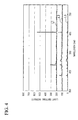
- FIG. 4 is a view showing the emission spectrum developed based on the light receiving result of the light receiving device 6.
- the horizontal axis represents a wavelength and the vertical axis represents emission intensity.
- the line L1 shows the emission spectrum when the partial pressure ratio of hydrogen with respect to the total pressure of the in-furnace gas G2 (the total pressure of the treatment room 12) is 1. That is, the line L1 shows the emission spectrum in the case where, from the acetylene supplied to the treatment room 12, all the acetylene is used for the carburizing reaction and all the in-furnace gas G2 (the in-furnace gas G2 emitted from the treatment room 12) in the treatment room 12 is hydrogen gas.
- the line 2 shows the emission spectrum when the partial pressure ratio of hydrogen with respect to the total pressure of the in-furnace gas G2 (total pressure of the treatment room 12) is 0.56. That is, the line L2 shows the emission spectrum in the case where, among acetylene supplied to the treatment room 12, about half the acetylene is used for the carburizing reaction and about half the in-furnace gas G2 (the in-furnace gas G2 emitted from the treatment room 12) in the treatment room 12 is hydrogen gas.
- the line L3 shows the emission spectrum when the partial pressure ratio of hydrogen with respect to the total pressure of the in-furnace gas G2 (total pressure of the treatment room 12) is 0. That is, the line L3 shows the emission spectrum in the case where, among acetylene supplied to the treatment room 12, all the acetylene is not used for the carburizing reaction and all the in-furnace gas G2 (the in-furnace gas G2 emitted from the treatment room 12) in the treatment room 12 is acetylene.
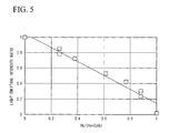
- FIG. 5 is plotted with a horizontal axis representing the partial pressure ratio of hydrogen with respect to the total pressure of the in-furnace gas G2 and a vertical axis representing the light receiving result (the peak intensity of a hydrocarbon derived from acetylene with respect to the peak intensity derived from hydrogen). Accordingly, it is understood that the composition of the in-furnace gas G2 and the light receiving result correlate.
- the relationship between the composition of the in-furnace gas G2 and the light intensity when the in-furnace gas G2 emits light is stored in advance in the storage device 9.
- this relationship can be obtained from, for example, at least one of a preliminary experiment or a simulation for example and can be stored in the storage device 9.
- the relationship between the partial pressure ratio of hydrogen (or the composition of the in-furnace gas G2) with respect to the total pressure of the in-furnace gas G2 and normalized value of light emission intensity corresponding to the partial pressure ratio (composition), as shown in FIG. 5 is stored in advance in the storage device 9.
- the ratio between the peak intensity derived from hydrogen and the peak intensity of hydrocarbon derived from acetylene is preferably used.
- the peak intensity derived from hydrogen may be used.
- the control device 8 controls, by using the adjustment mechanism 3B, the amount of the carburizing gas G1 supplied per unit time by the gas supply mechanism 3 based on the composition of the in-furnace gas G2 which is calculated by the processing device 7.
- the carburizing quality of the object to be treated S (the surface carburizing density, the carburization density distribution, the case hardness, the effective case depth after carburizing (carburized depth), or the like) changes corresponding to the composition of the in-furnace gas G2 (atmosphere of the treatment room 12).
- the control device 8 adjusts the amount of the carburizing gas G1 supplied per unit time by the gas supply mechanism 3.
- the adjustment is performed based on the composition of the in-furnace gas G2 calculated by the processing device 7 based on the light receiving result of the light receiving device 6 so as to optimize the composition (such as acetylene density) of the in-furnace gas G2, in other words, in order to obtain the composition of the in-furnace gas G2 in which desired carburizing quality is obtained. Accordingly, it is possible to obtain a desired state in the composition of the in-furnace gas G2 and to preferably perform the vacuum carburizing treatment with high reproducibility.
- the carburizing condition includes not only the amount of the carburizing gas G1 supplied per unit time by the gas supply mechanism 3 but also the carburizing time, the carburizing temperature, or the like. Accordingly, the control device 8 can obtain a desired state in the carburizing quality with respect to the object to be treated S by also adjusting the carburizing time, the carburizing temperature, or the like as the carburizing condition based on the calculated composition of the in-furnace gas G2. Also, the control device 8 may adjust the composition of the carburizing gas G1, which is supplied to the treatment room 12 from the gas supply mechanism 3, based on the calculated composition of the in-furnace gas G2.
- the present embodiment it is possible to calculate the composition of the in-furnace gas G2 optically and fast (with good response). Since the structure of the present embodiment can be made with relatively lower cost compared to a conventional sensor capable of detecting, for example, the hydrogen density, and is provided with good sensitivity, it is suitable for a feedback control and it is possible to improve the controllability thereof.
- the carburizing apparatus is the vacuum carburizing apparatus and the treatment room 12 of the carburizing furnace 2 has a high vacuum. Accordingly, it is possible to make the detection space 15 which is connected to the treatment room 12 in high vacuum without providing a new (another) vacuum system for increasing the vacuum of the detection space (discharge room) 15. Therefore, it is preferable to generate plasma in the detection space 15 having a high vacuum.
- the detection space 15 and the treatment room 12 of the carburizing furnace 2 are connected; accordingly it is possible to make the detection space 15 and the treatment room 12 of the carburizing furnace 2 have substantially the same environment (atmosphere). Therefore, it is possible to calculate the composition of the in-furnace gas G2 accurately since it is possible to emit light by using the in-furnace gas G2 in the detection space 15 which has substantially the same environment as the treatment room 12.
- the carburizing condition it is preferable to control the carburizing condition to obtain a desired carburizing quality and so it is possible to perform the treatment with respect to the object to be treated S with the desired carburizing quality. Also, in the present embodiment, it is possible to prevent problems such as generation of the soot in the carburizing furnace or the like from happening and so it is possible to simplify the maintenance work of the carburizing furnace.
- the light emitting device 5 causes the in-furnace gas G2 to emit light by generating plasma in the detection space (discharge room) 15 which includes the in-furnace gas G2, giving energy to the in-furnace gas G2, and forming the in-furnace gas G2 into an excited state.
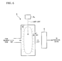
- the light emitting device 5 may be provided with a laser light emitting device 5L which is capable of emitting a laser light into a detection room 15' to which the in-furnace gas G2 is introduced as shown in a schematic view of FIG. 6 .
- the detection room 15' is connected to the treatment room 12 via the exhaust pipe 4L.
- the in-furnace gas G2 is introduced to the detection room 15'.
- the detection room 15' is made of a transparent object that transmits laser light.
- the light emitting device 5 can cause the in-furnace gas G2 to emit light by emitting a laser light into the in-furnace gas G2 from the laser light emitting device 5L and giving energy to the in-furnace gas G2. That is, since the in-furnace gas G2 becomes an excited state and emits light by being emitted with a laser, the light emitting device 5 can emit light by using the in-furnace gas G2 by also emitting a laser light into the in-furnace gas G2.
- the light emitting device 5 may emit light by using other methods such as burning the in-furnace gas G2 or the like as long as it is possible to emit light by giving energy to the in-furnace gas G2.
- the space 15 (15') is branched from the midstream of the exhaust pipe 4L.
- the electrodes 5B for generating plasma may be disposed in the midstream of the exhaust pipe 4L and the light generated by plasma may be received by the light receiving device 6 via a transmissive window which is disposed in a predetermined position of the exhaust pipe 4L.
- the transmissive window may be disposed in the midstream of the exhaust pipe 4L and the laser light may be emitted into the in-furnace gas G2 via the transmissive window.
Landscapes
- Chemical & Material Sciences (AREA)
- Engineering & Computer Science (AREA)
- Mechanical Engineering (AREA)
- Materials Engineering (AREA)
- Organic Chemistry (AREA)
- Metallurgy (AREA)
- Physics & Mathematics (AREA)
- Thermal Sciences (AREA)
- Crystallography & Structural Chemistry (AREA)
- Health & Medical Sciences (AREA)
- Chemical Kinetics & Catalysis (AREA)
- General Engineering & Computer Science (AREA)
- Pathology (AREA)
- Biochemistry (AREA)
- Analytical Chemistry (AREA)
- Life Sciences & Earth Sciences (AREA)
- Nuclear Medicine, Radiotherapy & Molecular Imaging (AREA)
- Immunology (AREA)
- General Physics & Mathematics (AREA)
- General Health & Medical Sciences (AREA)
- Plasma & Fusion (AREA)
- Solid-Phase Diffusion Into Metallic Material Surfaces (AREA)
- Investigating, Analyzing Materials By Fluorescence Or Luminescence (AREA)
- Investigating Or Analysing Materials By Optical Means (AREA)
Abstract
A carburizing apparatus that performs a vacuum carburizing treatment with respect to an object includes: a carburizing furnace that contains the object; a gas supply apparatus that supplies a carburizing gas to the carburizing furnace; a light emitting device that emits light by using an in-furnace gas inside of the carburizing furnace which is supplied with the carburizing gas; a light receiving device that receives light emitted from the light emitting device; and a processing device that calculates the composition of the in-furnace gas based on the light receiving result of the light receiving device.
Description
- The present invention relates to a carburizing apparatus and carburizing method.
Priority is claimed on Japanese Patent Application No.2007-43973, filed February 23, 2007 - A vacuum carburization, which is performed under reduced pressure, has been conventionally known as one of the carburizing treatments that are used for surface treatment of steel.
The following Patent documents disclose part of examples of techniques related to the vacuum carburization. - Patent Document 1: Japanese Unexamined Patent Application, first publication No.
2001-081543 - Patent Document 2: Japanese Unexamined Patent Application, first publication No.
2001-240954 - Patent Document 3: Japanese Unexamined Patent Application, first publication No.
2001-262313 - Patent Document 4: Japanese Unexamined Patent Application, first publication No.
2002-173759 - Patent Document 5: Japanese Unexamined Patent Application, first publication No.
2002-212702 - Patent Document 6: Japanese Unexamined Patent Application, first publication No.
2004-053507 - Patent Document 7: Japanese Unexamined Patent Application, first publication No.
2004-059959 - Patent Document 8: Japanese Unexamined Patent Application, first publication No.
2004-332075 - Patent Document 9: Japanese Unexamined Patent Application, first publication No.
2005-350729 - Patent Document 10: Japanese Unexamined Patent Application, first publication No.
2005-351761 - Conventionally, as one of the methods to confirm reproducibility of the vacuum carburization treatment, sampling inspections have been performed with respect to objects to be treated (steel) after being treated by the vacuum carburizing treatment. In particular, the vacuum carburizing treatment has been performed with respect to the objects to be treated by controlling, for example, various carburizing conditions (carburizing time, carburizing temperature, the amount of a carburizing gas supplied, or the like). The treatment has been followed by inspecting carburizing quality (surface carburization density, carburization density distribution, case hardness, effective case depth after carburizing, or the like) by sampling the objects to be treated after being treated by the vacuum carburizing treatment. The treatment has been further followed by confirming whether or not a desired carburizing quality has been obtained, or re-adjusting the carburizing conditions so as to obtain the desired carburizing quality.
- However, with the above-described method, in order to obtain the desired carburizing quality, a cumbersome process is necessary, in which quality confirmation results of the objects to be treated with carburizing needs to be fed back in each case. Also, in the case where the amount of the carburizing gas is not appropriate with respect to the size of the objects to be treated with carburizing, the following problems occur. For example, in the case where the amount of the carburizing gas is too little with respect to the size of the objects to be treated with carburizing, the carburizing quality fluctuates because the amount of the carburizing gas which is supplied to surfaces of the objects to be treated with carburizing fluctuates. In contrast, in the case where the amount of the carburizing gas is too much with respect to the size of the objects to be treated with carburizing, soot is generated in a carburizing furnace due to excessive gas that does not contribute to the carburizing, and accordingly, maintenance work for getting rid of the soot is frequently necessary.
- In order to perform the vacuum carburizing treatment with excellent reproducibility, it is preferable to control the composition of an in-furnace gas inside of the carburizing furnace. Accordingly, it is necessary to calculate the composition of the in-furnace gas immediately and accurately, use the calculated result, and perform appropriate treatments in order to have a desired composition of the in-furnace gas. However, conventionally, an effective method for calculating the composition of the in-furnace gas immediately and accurately has not been established. Accordingly, an effective method for calculating the composition of the in-furnace gas immediately and accurately has been demanded.
- The present invention was achieved in view of the forgoing circumstances and has an objective to provide a carburizing apparatus and carburizing method that enables calculations of the composition of the in-furnace gas immediately and accurately and preferably perform the vacuum carburizing treatment with high reproducibility.
- In order to solve the aforementioned problems, the present invention employs the following structures.
A first aspect of the present invention is a carburizing apparatus that performs a vacuum carburizing treatment with respect to an object. The carburizing apparatus includes: a carburizing furnace that contains the object; a gas supply apparatus that supplies a carburizing gas to the carburizing furnace; a light emitting device that emits light by using an in-furnace gas inside of the carburizing furnace which is supplied with the carburizing gas; a light-receiving device that receives light emitted from the light emitting device; and a processing device that calculates the composition of the in-furnace gas based on the light receiving result of the light receiving device. - In accordance with the first aspect of the present invention, since the light emitting device that emits light by using the in-furnace gas and the light-receiving device that receives light emitted from the light emitting device are provided, it is possible to optically calculate the composition of the in-furnace gas immediately and accurately based on the light receiving result of the light receiving device. Accordingly, by using the calculated result, it is possible to perform appropriate treatments in order to achieve desired composition of the in-furnace gas and preferably to perform the vacuum carburizing treatment with high reproducibility.
- In the carburizing apparatus of the above aspect, a structure may be employed, in which the light emitting device emits light by using the in-furnace gas introduced to a detection space which is connected to an internal space of the carburizing furnace.
- In accordance with the above structure, an exclusive detection space different from the internal space of the carburizing furnace for emitting light by the light emitting device is provided. Accordingly, it is possible to smoothly perform a light emitting operation using the light emitting device and a light receiving operation using the light-receiving device. Since the detection space is connected with the internal space of the carburizing furnace, the environment of the detection space corresponds to the internal space of the carburizing furnace. Accordingly, under the environment corresponding to the internal space of the carburizing furnace, it is possible to emit light by using the in-furnace gas.
- In the carburizing apparatus of the above aspect, a structure may be employed, in which the light emitting device emits light by imparting energy to the in-furnace gas.
- In accordance with the above structure, the light emitting device can emit light by forming the in-furnace gas into an excited state.
- In the carburizing apparatus of the above aspect, a structure may be employed, in which the light emitting device generates plasma in a space which includes the in-furnace gas.
- In accordance with the above structure, the light emitting device can emit light by forming the in-furnace gas into an excited state.
- In the carburizing apparatus of the above aspect, a structure may be employed, in which the light emitting device emits a laser light into the in-furnace gas.
- In accordance with the above structure, the light emitting device can emit light by forming the in-furnace gas into an excited state.
- In the carburizing apparatus of the above aspect, a structure may be employed, in which the light receiving device detects intensity of the light emitted from the light emitting device.
- In accordance with the above structure, since the light emitting device emits light having a predetermined wavelength and intensity corresponding to the composition of the in-furnace gas, it is possible to calculate the composition of the in-furnace gas accurately based on the light receiving result of the light receiving device.
- In the carburizing apparatus of the above aspect, a structure may be employed, in which a control device is provided that controls at least one of an amount of the carburizing gas supplied per unit time by the gas supply apparatus or the carburizing time based on the composition of the in-furnace gas calculated by the processing device.
- In accordance with the above structure, the control device can have a desired composition of the in-furnace gas and preferably perform the vacuum carburizing treatment with high reproducibility by controlling the amount of the carburizing gas per unit time supplied from the gas supply apparatus or by controlling the carburizing time based on the calculated composition of the in-furnace gas.
- A second aspect of the present invention is a carburizing method which performs the vacuum carburizing treatment with respect to the object. The carburizing method includes: supplying the carburizing gas to the carburizing furnace that contains the object; causing an in-furnace gas existing inside of the carburizing furnace which is supplied with the carburizing gas to emit light; receiving the light which is emitted and; calculating the composition of the in-furnace gas based on the light receiving result.
- In accordance with the second aspect of the present invention, since an operation which causes the in-furnace gas to emit light and an operation which receives the light which is emitted are performed, it is possible to optically calculate the composition of the in-furnace gas immediately and accurately based on the light receiving result. Accordingly, by using the calculated result, it is possible to perform appropriate treatments in order to have a desired composition of the in-furnace gas and preferably to perform the vacuum carburizing treatment with high reproducibility.
- In the carburizing method of the above aspect, a structure may be employed, in which the operation which receives the light includes an operation which detects the intensity of the light received and further includes an operation which calculates the relationship in advance between the composition of the in-furnace gas and the intensity of the light which caused the in-furnace gas to emit light. Accordingly, it is possible to calculate the composition of the in-furnace gas based on the relationship and the light intensity of the detected light.
- In accordance with the above method, by calculating the relationship between the composition of the in-furnace gas and the intensity of the light which the in-furnace gas emits in advance, it is possible to calculate the composition of the in-furnace gas accurately based on the relationship and the light intensity of the detected light.
- In accordance with the present invention, it is possible to calculate the state of the in-furnace gas inside of the carburizing furnace immediately and accurately. Accordingly, it is possible to preferably perform the vacuum carburizing treatment with high reproducibility.
-
-
FIG. 1 is an outline block diagram showing a carburizing apparatus in accordance with a present embodiment. -
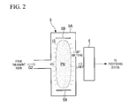
FIG. 2 is an enlarged view showing the vicinity of a light emitting device and of a light receiving device. -
FIG. 3A is a schematic view explaining the relationship between a carburizing condition and an in-furnace gas. -
FIG. 3B is a schematic view explaining the relationship between a carburizing condition and an in-furnace gas. -
FIG. 4 is a view showing an example of an emission spectrum developed based on a light receiving result of a light receiving device. -
FIG. 5 is a view showing the relationship between the partial pressure ratio and the normalized value of the light emission intensity corresponding to the partial pressure ratio. -
FIG. 6 is a schematic view showing an alternative example of a light emitting device. -
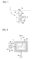
FIG. 7 is a schematic view showing an alternative example of a light emitting device. -
FIG. 8 is a schematic view showing an alternative example of a light emitting device. -
- 1
- Carburizing apparatus
- 2
- Carburizing furnace
- 3
- Gas supply mechanism
- 4
- Gas emission mechanism
- 5
- Light emitting device
- 6
- Light receiving device
- 7
- Processing device
- 8
- Control device
- 12
- Treatment room (internal space)
- 15
- Discharge room (detection space)
- Hereinbelow, embodiments of the present invention shall be described with reference to the appended drawings. The present invention shall not be limited to the following embodiments, and structural elements of the embodiments may be arbitrarily combined for example.
FIG. 1 is an outline block diagram showing a carburizing apparatus in accordance with the present embodiment. The present embodiment shall be described with a vacuum carburizing apparatus as an example of the carburizing apparatus, in which the carburizing apparatus performs a carburizing treatment under reduced pressure (below atmospheric pressure) with respect to objects to be treated such as steel. - In
FIG. 1 , acarburizing apparatus 1 is provided with: a carburizingfurnace 2 that contains an object to be treated S such as a steel which is to be treated with a vacuum carburizing treatment; agas supply mechanism 3 that supplies carburizing gas G1 to thecarburizing furnace 2; agas emission mechanism 4 that emits to the outside an in-furnace gas G2 which exists inside of thecarburizing furnace 2 and is supplied with the carburizing gas G1; alight emitting device 5 that emits light by using the in-furnace gas G2 existing inside of thecarburizing furnace 2 which is supplied with the carburizing gas G1; alight receiving device 6 that receives light emitted from thelight emitting device 5; a processing device 7 that calculates the composition of the in-furnace gas G2 based on the light receiving result of thelight receiving apparatus 6; and acontrol device 8 that controls the whole operation of thecarburizing apparatus 1. To thecontrol device 8, astorage device 9 that stores each piece of information about the carburizing treatment; anoutput device 10 that is capable of outputting information about the carburizing treatment; and aninput device 11 that is capable of inputting operational signals to thecontrol device 8 are connected. Theoutput device 10 may be a display, a printer, or the like. Theinput device 11 may be a keyboard, a mouse, or the like. - The
carburizing furnace 2 has an internal space (treatment room) 12 where the object to be treated S is disposed. Thecarburizing furnace 2 has afurnace wall 2A and anadiabatic wall 2B. Thetreatment room 12 is formed inside of theadiabatic wall 2B. - The
gas supply mechanism 3 supplies the carburizing gas G1 to thetreatment room 12 of thecarburizing furnace 2. Thegas supply mechanism 3 is provided with: a gas supply device 3Athat is capable of sending the carburizing gas G1; anair supply opening 3M that is formed in part of thetreatment room 12; and anair supply pipe 3L that connects thegas supply device 3A and theair supply opening 3M. Thegas supply mechanism 3 is provided with anadjustment mechanism 3B that adjusts the amount of the carburizing gas G1 supplied per unit time to thetreatment room 12. Theadjustment mechanism 3B includes a bulb mechanism and is connected to thecontrol device 8. Thecontrol device 8 can adjust the amount of the carburizing gas G1 supplied by thegas supply mechanism 3 per unit time to thetreatment room 12 by controlling theadjustment mechanism 3B. - The carburizing gas G1, which includes a predetermined hydrocarbon system gas, is a gas that is supplied to the
treatment room 12 so as to perform the vacuum carburizing treatment on the object to be treated S. In the present embodiment, thegas supply mechanism 3 supplies acetylene (C2H2) to thetreatment room 12 as the carburizing gas G1. - The
gas emission mechanism 4 emits the in-furnace gas G2, existing inside of thetreatment room 12 of thecarburizing furnace 2 where the carburizing gas G1 is supplied, to the outside of thetreatment room 12. Thegas emission mechanism 4 includes a vacuum system such as a vacuum pump or the like and is provided with: agas suction device 4A that can suction gas; anexhaust opening 4M that is formed in part of thetreatment room 12; and anexhaust pipe 4L that connects thegas suction device 4A to theexhaust opening 4M. - The in-furnace gas G2 is a gas which was supplied to the
treatment room 12 by thegas supply mechanism 3. The in-furnace gas G2 includes at least one of the following gases: the gas (reaction gas) which is left after the carburizing gas G1 is chemically reacted (carburizing reaction) in thetreatment room 12 by the carburizing treatment, or the gas (non-reaction gas) which is the carburizing gas which is not used for the carburizing treatment and hasn't cause the carburizing reaction. For example, in accordance with the carburizing condition, there is a case, in which not all of the carburizing gas G1 supplied to thetreatment room 12 is used for the carburizing reaction. In this case, there exists both the gas (reaction gas) used for the carburizing treatment and the gas (non-reaction gas) not used for the carburizing treatment in thetreatment room 12. The gas which is emitted from thetreatment room 12 includes both the reaction gas and the non-reaction gas. - As described above, in the present embodiment, acetylene (C2H2) is supplied in the
treatment room 12 as the carburizing gas G1. The part of the acetylene supplied to thetreatment room 12 which caused carburizing reaction with the object to be treated S generates a carbon component and a hydrogen component. That is, the carburizing reaction of the present embodiment is represented by C2H2 →H2 + 2C. The carbon component generated by the carburizing reaction permeates (carburize) the surface of the object to be treated S and the hydrogen is emitted from thetreatment room 12. That is, in the present embodiment, a main component of the reaction gas after the carburizing gas G1 causing the carburizing reaction is hydrogen gas. Also, in the present embodiment, a main component of the non-reaction gas which was not used for the carburizing treatment and did not cause the chemical reaction is acetylene. - The
light emitting device 5 emits light by using the in-furnace gas G2. Thelight emitting device 5 emits light by using the in-furnace gas G2 which is introduced to adetection space 15 which is connected to thetreatment room 12 of thecarburizing furnace 2. Thelight emitting device 5 is provided with adischarge member 5A that has an internal space (detection space, discharge room) 15 which is connected to the midstream of theexhaust pipe 4L and an electrode which is disposed in thedischarge room 15 of thedischarge member 5A that generates plasma in thedischarge room 15. Thedischarge member 5A can be made of a discharge tube (for example, a Geissler tube). Theexhaust pipe 4L and thedischarge room 15 are connected and thetreatment room 12 and thedischarge room 15 are connected via theexhaust pipe 4L. At least part of the in-furnace gas G2 which is emitted from thetreatment room 12 and flows in theexhaust pipe 4L is introduced to thedischarge room 15. Thelight emitting device 5 generates plasma in thedischarge room 15 where the in-furnace gas G2 is introduced. The light emitting device causes the in-furnace gas G2 to emit light by generating plasma. As described above, in the present embodiment, thelight emitting device 5 can emit light by using the in-furnace gas G2 which is introduced to thedischarge room 15 which is connected to thetreatment room 12 of thecarburizing furnace 2. - The
light receiving device 6 receives light emitted from thelight emitting device 5. Thelight receiving device 6 includes a spectroscope disposed in the vicinity of thedischarge member 5A of thelight emitting device 5. Thelight receiving device 6 including the spectroscope can detect the light intensity and the emission spectrum of the light emitted from thedischarge member 5A of thelight emitting device 5. Thelight receiving device 6 is connected to the processing device 7 (control device 8) and detection result (light receiving result) of thelight receiving device 6 is output to the processing device 7 (control device 8). - The processing device 7 is provided with a CPU or the like and is capable of performing a predetermined arithmetic processing, various information processing, or the like. The light receiving result of the
light receiving device 6 is output to the processing device 7. The processing device 7 can calculate the composition of the in-furnace gas G2 based on the light receiving result of thelight receiving device 6. - The
carburizing apparatus 1 is provided with atemperature adjustment device 13 which can adjust at least one of the temperature of thetreatment room 12 or the temperature of the object to be treated S which is contained in thetreatment room 12. At least part of thetemperature adjustment device 13 is disposed in thetreatment room 12. Thetemperature adjustment device 13 includes a heating device (heater). Thecontrol device 8 can control (heat) the temperature of thetreatment room 12 and the object to be treated S which is contained in thetreatment room 12 to a predetermined temperature by controlling thetemperature adjustment device 13 including the heating device. Also, thecarburizing apparatus 1 is provided with atemperature sensor 16 which can detect the temperature of thetreatment room 12. At least part of the temperature sensor 16 (a probe or the like) is disposed in thetreatment room 12. Thetemperature sensor 16 is connected to thecontrol device 8 and a detection result of thetemperature sensor 16 is output to thecontrol device 8. Thecontrol device 8 can adjust the temperature of thetreatment room 12 to a predetermined temperature by controlling thetemperature adjustment device 13 including the heating device based on the detection result of thetemperature sensor 16. - The
control device 8 can adjust (reduce) the pressure of thetreatment room 12 by controlling thegas suction device 4A including the vacuum system. Thecarburizing apparatus 1 is provided with apressure sensor 17 which can detect the pressure of thetreatment room 12. At least part of the pressure sensor 17 (probe or the like) is disposed in thetreatment room 12. Thepressure sensor 17 is connected to thecontrol device 8 and a detection result of thepressure sensor 17 is output to thecontrol device 8. Thecontrol device 8 can adjust the pressure of thetreatment room 12 to a desired pressure by controlling thegas suction device 4A including the vacuum system based on the detection result of thepressure sensor 17. - Next, an operation of the
carburizing apparatus 1 having the above-described structure shall be described. In order to perform the vacuum carburizing treatment with respect to the object to be treated S, thecontrol device 8 heats thetreatment room 12 of thecarburizing furnace 2 which contains the object to be treated S by using thetemperature adjustment device 13. At the same time, thecontrol device 8 reduces the pressure (increase vacuum) of thetreatment room 12 by suctioning the gas in thetreatment room 12 by using thegas emission mechanism 4. After thetreatment room 12 is set to a predetermined heating state and pressure reduced state, thecontrol device 8 supplies a predetermined amount of the carburizing gas G1 per unit time from thegas supply mechanism 3 with respect to thetreatment room 12 of thecarburizing furnace 2 which contains the object to be treated S. Thecontrol device 8 performs the vacuum carburizing treatment with respect to the object to be treated S for a predetermined time while the control device supplying the predetermined amount of the carburizing gas G1 per unit time from thegas supply mechanism 3 to thetreatment room 12, emitting the gas in thetreatment room 12 from thegas emission mechanism 4, and maintaining a predetermined heating state and pressure reduced state of thetreatment room 12. - The in-furnace gas G2 in the
treatment room 12 is emitted via theexhaust opening 4M and flows in theexhaust pipe 4L. Part of the in-furnace gas G2 flowing in theexhaust pipe 4L flows toward to thegas suction device 4A and another part of the in-furnace gas G2 flows into thedischarge room 15 of thelight emitting device 5. Thecontrol device 8 causes the in-furnace gas G2 to emit light by using thelight emitting device 5. -
FIG. 2 is an enlarged view showing the vicinity of thelight emitting device 5 and thelight receiving device 6. As shown inFIG. 2 , thelight emitting device 5 is provided with thedischarge member 5A having thedischarge room 15 andelectrodes 5B that are disposed in thedischarge room 15 of thedischarge member 5A and generate plasma in thedischarge room 15. Thelight emitting device 5 generates plasma in thedischarge room 15. The in-furnace gas G2 emitted from thetreatment room 12 is introduced into thedischarge room 15 and is supplied to a plasma generation area PU, in which plasma is generated, in thedischarge room 15. Thelight emitting device 5 causes the in-furnace gas G2 to emit light by generating plasma. - The
light receiving device 6 receives light, which is emitted by the in-furnace gas G2 inside thelight emitting device 5. The detection result (light receiving result) of thelight receiving device 6 is output to the processing device 7. The processing device 7 calculates the composition of the in-furnace gas G2 based on the light receiving result of thelight receiving device 6. In the present embodiment, the vacuum carburizing treatment with respect to the object to be treated S in thetreatment room 12, the light emitting operation by thelight emitting device 5, and the light receiving operation by thelight receiving device 6 are performed in parallel. That is, while the vacuum carburizing treatment is performed with respect to the object to be treated S, the light receiving operation by thelight receiving device 6 and the processing operation by the processing device 7 (operation that calculates the composition of the in-furnace gas G2) based on the light receiving result are performed in real time. - The
control device 8 controls, by using theadjustment mechanism 3B, the amount of the carburizing gas G1 supplied per unit time with respect to thetreatment room 12 by thegas supply mechanism 3 based on the composition of the in-furnace gas G2 which is calculated by the processing device 7. That is, in the present embodiment, thecontrol device 8 controls in real time a supply operation of the carburizing gas G1 with respect to the treatment room 12 (control theadjustment mechanism 3B) by thegas supply mechanism 3 based on the composition of the in-furnace gas G2 which is calculated by the processing device 7 while the vacuum carburizing treatment is performed with respect to the object to be treated S. - Next, an operation, in which the processing device 7 calculates the composition of the in-furnace gas G2 based on the light receiving result of the
light receiving device 6, shall be described. - As described above, the in-furnace gas G2 includes the reaction gas, which is left after the carburizing gas G1 causing the carburizing reaction in the
treatment room 12 and the non-reaction gas which is not used for the carburizing treatment and has not caused the carburizing reaction. In the present embodiment, the in-furnace gas G2 includes hydrogen as the reaction gas and acetylene as the non-reaction gas. - In the present embodiment, the
gas supply mechanism 3 supplies the predetermined amount of the carburizing gas G1 per unit time to thetreatment room 12. However, in accordance with various carburizing conditions such as carburizing time, carburizing temperature, the supply amount of the carburizing gas, or the like, the amount of the carbon component permeated the object to be treated S, in other words, a reaction speed of the carburizing reaction might fluctuate. When the amount of the carbon component that permeates the object to be treated S changes, the amount of the reaction gas (hydrogen gas) in thetreatment room 12 changes in correspondence therewith. - Here, carburizing time means elapsed time since the carburizing treatment started. Carburizing temperature means the temperature of the
treatment room 12, in which the carburizing treatment is performed. The supply amount of the carburizing gas means the amount of the carburizing gas G1 supplied per unit time with respect to thetreatment room 12. - For example, as shown in a schematic view of
FIG. 3A , in the case where carburizing time is short and the amount of the carbon component at the surface of the object to be treated S (the amount of carbon already permeated at the surface of the object to be treated S) is low, there is enough room for the carbon component to permeate the surface of the object to be treated S. In this case, from the acetylene supplied to thetreatment room 12, most of the acetylene is used for the carburizing reaction and the amount of carbon component which permeates the object to be treated S (reaction speed of the carburizing reaction) increases. In this case, the gas in thetreatment room 12 and the in-furnace gas G2 emitted from thetreatment room 12 include a lot of the reaction gas (hydrogen gas). - On the other hand, as shown in a schematic view of
FIG. 3B , in a case where the carburizing time is long and the amount of the carbon component at the surface of the object to be treated S (the amount of carbon already permeated at the surface of the object to be treated S) is high, in other words, the amount of carbon component capable of permeating the surface of the object to be treated S has almost reached a saturated state, there is little room for the carbon component to permeate the surface of the object to be treated S. In this case, from the acetylene supplied to thetreatment room 12, most of the acetylene is not used for the carburizing reaction and the amount of carbon component which permeates the object to be treated S (reaction speed of the carburizing reaction) decreases. In this case, the gas in thetreatment room 12 and the in-furnace gas G2 emitted from thetreatment room 12 include a lot of the non-reaction gas (acetylene). - As described above, in accordance with carburizing time, the composition of the in-furnace gas G2 changes. In accordance with not only carburizing time, but also with the carburizing conditions such as carburizing temperature, the amount of the carburizing gas supplied per unit time to the
treatment room 12, or the like, the composition of the in-furnace gas G2 changes. That is, in accordance with the carburizing conditions such as carburizing time, the carburizing temperature, the amount of the carburizing gas supplied per unit time, or the like, the composition of the in-furnace gas G2 changes. - In accordance with the composition of the in-furnace gas G2, the state of the light changes at the time when the in-furnace gas G2 inside the
light emitting device 5 emits light. In particular, in accordance with the composition of the in-furnace gas G2, the light intensity and the emission spectrum change at the time when the in-furnace gas G2 emits light inside thelight emitting device 5. For example, when the in-furnace gas G2, having the composition shown inFIG. 3A (the composition with a lot of hydrogen), inside thelight emitting device 5 emits light, an emission spectrum having a peak intensity derived from hydrogen is obtained. Also, when the in-furnace gas G2, having the composition shown inFIG. 3B (the composition with a lot of acetylene), emits light inside thelight emitting device 5, the emission spectrum having a peak intensity derived from acetylene is obtained. -
FIG. 4 is a view showing the emission spectrum developed based on the light receiving result of thelight receiving device 6. InFIG. 4 , the horizontal axis represents a wavelength and the vertical axis represents emission intensity. InFIG. 4 , the line L1 shows the emission spectrum when the partial pressure ratio of hydrogen with respect to the total pressure of the in-furnace gas G2 (the total pressure of the treatment room 12) is 1. That is, the line L1 shows the emission spectrum in the case where, from the acetylene supplied to thetreatment room 12, all the acetylene is used for the carburizing reaction and all the in-furnace gas G2 (the in-furnace gas G2 emitted from the treatment room 12) in thetreatment room 12 is hydrogen gas. - Also, in
FIG. 4 , theline 2 shows the emission spectrum when the partial pressure ratio of hydrogen with respect to the total pressure of the in-furnace gas G2 (total pressure of the treatment room 12) is 0.56. That is, the line L2 shows the emission spectrum in the case where, among acetylene supplied to thetreatment room 12, about half the acetylene is used for the carburizing reaction and about half the in-furnace gas G2 (the in-furnace gas G2 emitted from the treatment room 12) in thetreatment room 12 is hydrogen gas. - Also, in
FIG. 4 , the line L3 shows the emission spectrum when the partial pressure ratio of hydrogen with respect to the total pressure of the in-furnace gas G2 (total pressure of the treatment room 12) is 0. That is, the line L3 shows the emission spectrum in the case where, among acetylene supplied to thetreatment room 12, all the acetylene is not used for the carburizing reaction and all the in-furnace gas G2 (the in-furnace gas G2 emitted from the treatment room 12) in thetreatment room 12 is acetylene. - As described above, in accordance with the composition of the in-furnace gas G2, the light receiving result of the
light receiving device 6, which receives light emitted from thelight emitting device 5 which emits light by using the in-furnace gas G2, changes. - Accordingly, the processing device 7 can calculate the partial pressure ratio of hydrogen with respect to the total pressure of the in-furnace gas G2 based on the light receiving result of the
light receiving device 6. Since the partial pressure ratio of hydrogen with respect to the total pressure of the in-furnace gas G2 corresponds to the composition of the in-furnace gas G2, the processing device 7 can calculate the composition of the in-furnace gas G2 based on the light receiving result of thelight receiving device 6. -
FIG. 5 is plotted with a horizontal axis representing the partial pressure ratio of hydrogen with respect to the total pressure of the in-furnace gas G2 and a vertical axis representing the light receiving result (the peak intensity of a hydrocarbon derived from acetylene with respect to the peak intensity derived from hydrogen). Accordingly, it is understood that the composition of the in-furnace gas G2 and the light receiving result correlate. - In the present embodiment, the relationship between the composition of the in-furnace gas G2 and the light intensity when the in-furnace gas G2 emits light is stored in advance in the
storage device 9. Here, this relationship can be obtained from, for example, at least one of a preliminary experiment or a simulation for example and can be stored in thestorage device 9. In the present embodiment, the relationship between the partial pressure ratio of hydrogen (or the composition of the in-furnace gas G2) with respect to the total pressure of the in-furnace gas G2 and normalized value of light emission intensity corresponding to the partial pressure ratio (composition), as shown inFIG. 5 , is stored in advance in thestorage device 9. Here, for the light emission intensity, the ratio between the peak intensity derived from hydrogen and the peak intensity of hydrocarbon derived from acetylene is preferably used. For a simplified case, the peak intensity derived from hydrogen may be used. - The
control device 8 controls, by using theadjustment mechanism 3B, the amount of the carburizing gas G1 supplied per unit time by thegas supply mechanism 3 based on the composition of the in-furnace gas G2 which is calculated by the processing device 7. - It is considered that the carburizing quality of the object to be treated S (the surface carburizing density, the carburization density distribution, the case hardness, the effective case depth after carburizing (carburized depth), or the like) changes corresponding to the composition of the in-furnace gas G2 (atmosphere of the treatment room 12). In other words, since it is considered that the carburizing quality of the object to be treated S and the composition of the in-furnace gas G2 correlate, the
control device 8 adjusts the amount of the carburizing gas G1 supplied per unit time by thegas supply mechanism 3. Here, the adjustment is performed based on the composition of the in-furnace gas G2 calculated by the processing device 7 based on the light receiving result of thelight receiving device 6 so as to optimize the composition (such as acetylene density) of the in-furnace gas G2, in other words, in order to obtain the composition of the in-furnace gas G2 in which desired carburizing quality is obtained. Accordingly, it is possible to obtain a desired state in the composition of the in-furnace gas G2 and to preferably perform the vacuum carburizing treatment with high reproducibility. - Also, as described above, the carburizing condition includes not only the amount of the carburizing gas G1 supplied per unit time by the
gas supply mechanism 3 but also the carburizing time, the carburizing temperature, or the like. Accordingly, thecontrol device 8 can obtain a desired state in the carburizing quality with respect to the object to be treated S by also adjusting the carburizing time, the carburizing temperature, or the like as the carburizing condition based on the calculated composition of the in-furnace gas G2. Also, thecontrol device 8 may adjust the composition of the carburizing gas G1, which is supplied to thetreatment room 12 from thegas supply mechanism 3, based on the calculated composition of the in-furnace gas G2. - As described above, it is possible to calculate the composition of the in-furnace gas G2 immediately and accurately in real time since the composition of the in-furnace gas G2 inside of the
carburizing furnace 2 is calculated optically. - In the present embodiment, it is possible to calculate the composition of the in-furnace gas G2 optically and fast (with good response). Since the structure of the present embodiment can be made with relatively lower cost compared to a conventional sensor capable of detecting, for example, the hydrogen density, and is provided with good sensitivity, it is suitable for a feedback control and it is possible to improve the controllability thereof.
- In the present embodiment, the carburizing apparatus is the vacuum carburizing apparatus and the
treatment room 12 of thecarburizing furnace 2 has a high vacuum. Accordingly, it is possible to make thedetection space 15 which is connected to thetreatment room 12 in high vacuum without providing a new (another) vacuum system for increasing the vacuum of the detection space (discharge room) 15. Therefore, it is preferable to generate plasma in thedetection space 15 having a high vacuum. - The
detection space 15 and thetreatment room 12 of thecarburizing furnace 2 are connected; accordingly it is possible to make thedetection space 15 and thetreatment room 12 of thecarburizing furnace 2 have substantially the same environment (atmosphere). Therefore, it is possible to calculate the composition of the in-furnace gas G2 accurately since it is possible to emit light by using the in-furnace gas G2 in thedetection space 15 which has substantially the same environment as thetreatment room 12. - Based on the calculated composition of the in-furnace gas G2, among the carburizing conditions, by adjusting in particular the amount of the carburizing gas G1 supplied per unit time with respect to the
treatment room 12, it is possible to obtain a desired composition of the in-furnace gas G2. That is, the present embodiment calculates the composition of the in-furnace gas G2 in real time by using thelight emitting device 5, thelight receiving device 6, the processing device 7, and the like. Based on the calculated result, it is possible to implement a feedback control which adjusts the amount of the carburizing gas G1 supplied per unit time with respect to thetreatment room 12 for optimizing the carburizing condition so as to obtain a desired carburizing quality. Accordingly, it is preferable to perform the vacuum carburizing treatment with respect to the object to be treated S with high reproducibility. Therefore, it is possible to obtain the object to be treated S with a desired carburizing quality. - In the present embodiment, it is preferable to control the carburizing condition to obtain a desired carburizing quality and so it is possible to perform the treatment with respect to the object to be treated S with the desired carburizing quality. Also, in the present embodiment, it is possible to prevent problems such as generation of the soot in the carburizing furnace or the like from happening and so it is possible to simplify the maintenance work of the carburizing furnace.
- In the present embodiment, the
light emitting device 5 causes the in-furnace gas G2 to emit light by generating plasma in the detection space (discharge room) 15 which includes the in-furnace gas G2, giving energy to the in-furnace gas G2, and forming the in-furnace gas G2 into an excited state. However, thelight emitting device 5 may be provided with a laserlight emitting device 5L which is capable of emitting a laser light into a detection room 15' to which the in-furnace gas G2 is introduced as shown in a schematic view ofFIG. 6 . The detection room 15' is connected to thetreatment room 12 via theexhaust pipe 4L. The in-furnace gas G2 is introduced to the detection room 15'. The detection room 15' is made of a transparent object that transmits laser light. Thelight emitting device 5 can cause the in-furnace gas G2 to emit light by emitting a laser light into the in-furnace gas G2 from the laserlight emitting device 5L and giving energy to the in-furnace gas G2. That is, since the in-furnace gas G2 becomes an excited state and emits light by being emitted with a laser, thelight emitting device 5 can emit light by using the in-furnace gas G2 by also emitting a laser light into the in-furnace gas G2. - The
light emitting device 5 may emit light by using other methods such as burning the in-furnace gas G2 or the like as long as it is possible to emit light by giving energy to the in-furnace gas G2. - In the above-described embodiment, the space 15 (15') is branched from the midstream of the
exhaust pipe 4L. However, as shown inFIG. 7 , theelectrodes 5B for generating plasma may be disposed in the midstream of theexhaust pipe 4L and the light generated by plasma may be received by thelight receiving device 6 via a transmissive window which is disposed in a predetermined position of theexhaust pipe 4L. Also, the transmissive window may be disposed in the midstream of theexhaust pipe 4L and the laser light may be emitted into the in-furnace gas G2 via the transmissive window. - In the present embodiment, the
light emitting device 5 emits light by using the in-furnace gas G2 flowing in theexhaust pipe 4L. However, as shown inFIG. 8 for example, adetection member 5A' forming anexclusive detection space 115, which is connected to thetreatment room 12 of thecarburizing furnace 2, may be provided and so the light emittingdevice 5 may emit light by using the in-furnace gas G2 which is introduced to thedetection space 115.
Claims (9)
- A carburizing apparatus that performs a vacuum carburizing treatment with respect to an object comprising:a carburizing furnace that contains the object;a gas supply apparatus that supplies a carburizing gas to the carburizing furnace;a light emitting device that emits light by using an in-furnace gas inside of the carburizing furnace which is supplied with the carburizing gas;a light receiving device that receives light emitted from the light emitting device; anda processing device that calculates the composition of the in-furnace gas based on the light receiving result of the light receiving device.
- The carburizing apparatus according to Claim 1, wherein
the light emitting device emits light by using the in-furnace gas which is introduced to a detection space connected to an internal space of the carburizing furnace. - The carburizing apparatus according to Claim 1, wherein
the light emitting device emits light by imparting energy to the in-furnace gas. - The carburizing apparatus according to Claim 3, wherein
the light emitting device generates plasma in a space which includes the in-furnace gas. - The carburizing apparatus according to Claim 3, wherein
the light emitting device emits a laser light into the in-furnace gas. - The carburizing apparatus according to Claim 1, wherein
the light receiving device detects the light intensity emitted from the light emitting device. - The carburizing apparatus according to Claim 1, further comprising:a control device that controls at least one of an amount of the carburizing gas supplied per unit time by the gas supply apparatus or a carburizing time based on the composition of the in-furnace gas calculated by the processing device.
- A carburizing method that performs a vacuum carburizing treatment with respect to an object comprising:supplying a carburizing gas to a carburizing furnace that contains the object;causing an in-furnace gas existing inside of the carburizing furnace which is supplied with the carburizing gas to emit light;receiving the light which is emitted; andcalculating a composition of the in-furnace gas based on the light receiving result.
- The carburizing method according to Claim 8, wherein the receiving the light further comprising detecting intensity of the light received; and the carburizing method further comprising:calculating the relationship in advance between the composition of the in-furnace gas and the intensity of the light which caused the in-furnace gas to emit light; andcalculating the composition of the in-furnace gas based on the relationship andthe light intensity which is detected.
Applications Claiming Priority (2)
| Application Number | Priority Date | Filing Date | Title |
|---|---|---|---|
| JP2007043973A JP5233131B2 (en) | 2007-02-23 | 2007-02-23 | Carburizing apparatus and carburizing method |
| PCT/JP2008/052411 WO2008102684A1 (en) | 2007-02-23 | 2008-02-14 | Carburizing apparatus and carburizing method |
Publications (2)
| Publication Number | Publication Date |
|---|---|
| EP2128301A1 true EP2128301A1 (en) | 2009-12-02 |
| EP2128301A4 EP2128301A4 (en) | 2011-05-11 |
Family
ID=39709961
Family Applications (1)
| Application Number | Title | Priority Date | Filing Date |
|---|---|---|---|
| EP08711253A Withdrawn EP2128301A4 (en) | 2007-02-23 | 2008-02-14 | Carburizing apparatus and carburizing method |
Country Status (9)
| Country | Link |
|---|---|
| US (1) | US20090320962A1 (en) |
| EP (1) | EP2128301A4 (en) |
| JP (1) | JP5233131B2 (en) |
| KR (1) | KR20090104876A (en) |
| CN (1) | CN101617063A (en) |
| CA (1) | CA2679012A1 (en) |
| RU (1) | RU2429309C2 (en) |
| TW (1) | TW200842205A (en) |
| WO (1) | WO2008102684A1 (en) |
Cited By (4)
| Publication number | Priority date | Publication date | Assignee | Title |
|---|---|---|---|---|
| US9617632B2 (en) | 2012-01-20 | 2017-04-11 | Swagelok Company | Concurrent flow of activating gas in low temperature carburization |
| EP3412792A1 (en) * | 2017-06-07 | 2018-12-12 | Shanghai Yibai Industrial Furnaces Co., Ltd. | Atmospheric-pressure acetylene carburizing furnace |
| US10156006B2 (en) | 2009-08-07 | 2018-12-18 | Swagelok Company | Low temperature carburization under soft vacuum |
| WO2019162681A1 (en) * | 2018-02-22 | 2019-08-29 | Gencoa Ltd | Plasma monitoring system |
Families Citing this family (15)
| Publication number | Priority date | Publication date | Assignee | Title |
|---|---|---|---|---|
| DE102010012832B4 (en) * | 2010-03-25 | 2016-01-21 | Benteler Automobiltechnik Gmbh | Automotive column |
| NL1039971C2 (en) * | 2012-12-24 | 2014-06-25 | Bosch Gmbh Robert | Heat treatment process in a manufacturing method of a ring set for a drive belt. |
| JP6443961B2 (en) * | 2014-06-11 | 2018-12-26 | 株式会社Ihi | Carburizing equipment |
| JP6613402B2 (en) * | 2015-03-13 | 2019-12-04 | Vista株式会社 | Vacuum exhaust monitoring device |
| CN105951032A (en) * | 2016-05-25 | 2016-09-21 | 上海颐柏热处理设备有限公司 | Vacuum carburizing furnace for automatically controlling furnace atmosphere and control method |
| KR101883273B1 (en) | 2017-07-05 | 2018-08-01 | 한국생산기술연구원 | Base Material Input And Output/Cooling Assembly of Carburizing Apparatus |
| CN107448172A (en) * | 2017-07-12 | 2017-12-08 | 常熟市虹桥铸钢有限公司 | A kind of manufacture method of mining machinery rig rotary guide sleeve |
| JP7080083B2 (en) * | 2018-03-27 | 2022-06-03 | 大阪瓦斯株式会社 | Calorific value measuring device and calorific value measuring method |
| JP6853230B2 (en) * | 2018-11-12 | 2021-03-31 | 中外炉工業株式会社 | An acetylene gas concentration estimation device, an acetylene gas appropriate amount estimation device, and a vacuum carburizing device equipped with the device. |
| JP7430385B2 (en) * | 2020-03-25 | 2024-02-13 | 地方独立行政法人大阪産業技術研究所 | Surface hardening treatment method and device using laser light |
| JP7039096B2 (en) * | 2020-03-31 | 2022-03-22 | アトナープ株式会社 | Control method of gas analyzer, process monitoring device, gas analyzer |
| FR3127041B1 (en) * | 2021-09-14 | 2023-08-25 | Partelec | Sensor and method for measuring gas concentrations in a gas mixture. |
| JP2026071422A (en) * | 2023-03-17 | 2026-04-30 | 高圧ガス工業株式会社 | Carburizing apparatus and carburizing method |
| KR102773979B1 (en) | 2023-08-08 | 2025-02-27 | (주) 오로스테크놀로지 | Ellipsometer for efficient utilization of light and method using them |
| CN120330655B (en) * | 2025-06-20 | 2025-08-22 | 法垄热工技术(上海)有限公司 | Workpiece carburizing process with gas-regulated interference image system |
Family Cites Families (22)
| Publication number | Priority date | Publication date | Assignee | Title |
|---|---|---|---|---|
| JPS4930896B1 (en) * | 1969-01-23 | 1974-08-16 | ||
| DE2636273C3 (en) * | 1976-08-12 | 1980-02-07 | Ipsen Industries International Gmbh, 4190 Kleve | Method for controlling carburization of parts in a vacuum furnace |
| US5139584A (en) * | 1989-07-13 | 1992-08-18 | Solo Fours Industriels Sa | Carburization process |
| RU2034092C1 (en) * | 1993-02-17 | 1995-04-30 | Сергей Зиновьевич Васильев | Method for ecologically clean carburizing of metal parts |
| US6046809A (en) * | 1998-02-04 | 2000-04-04 | S3 Incorporated | Real-time in situ multiple gas species sensing method |
| US6043881A (en) * | 1998-03-06 | 2000-03-28 | Praxair Technology Inc | Sample cell for gaseous emission spectroscopy |
| RU2157988C2 (en) * | 1998-06-15 | 2000-10-20 | Томский политехнический университет | Method for nuclear-absorption spectral analysis of elementary composition of material and device which implements said method |
| JP4467674B2 (en) * | 1999-08-31 | 2010-05-26 | 三菱重工業株式会社 | Gas concentration measuring device |
| JP2001081543A (en) | 1999-09-14 | 2001-03-27 | Chugai Ro Co Ltd | Vacuum carburizing method |
| JP3321732B2 (en) | 2000-03-02 | 2002-09-09 | 光洋サーモシステム株式会社 | Vacuum carburizing method and carburizing furnace for implementing the method |
| JP3448805B2 (en) | 2000-03-15 | 2003-09-22 | 光洋サーモシステム株式会社 | Vacuum carburizing method |
| JP2002173759A (en) * | 2000-12-05 | 2002-06-21 | Toho Gas Co Ltd | Vacuum carburizing atmosphere gas control system and vacuum carburizing apparatus used in the system |
| JP3531736B2 (en) | 2001-01-19 | 2004-05-31 | オリエンタルエンヂニアリング株式会社 | Carburizing method and carburizing device |
| FR2834052B1 (en) * | 2001-12-20 | 2004-03-19 | Snecma Moteurs | PROCESS FOR MONITORING THE CONDUCT OF A PROCESS USING REACTIVE GAS CONTAINING ONE OR MORE GAS HYDROCARBONS |
| JP4137546B2 (en) | 2002-07-23 | 2008-08-20 | 東邦瓦斯株式会社 | Concentration cell type hydrogen sensor for hydrocarbon cracking gas |
| JP2004059959A (en) | 2002-07-25 | 2004-02-26 | Oriental Engineering Co Ltd | Vacuum carburizing method and vacuum carburizing apparatus |
| JP2004332075A (en) | 2003-05-09 | 2004-11-25 | Toho Gas Co Ltd | Carburizing control method and carburizing apparatus using the method |
| JP4131682B2 (en) * | 2003-06-30 | 2008-08-13 | 三菱重工業株式会社 | Gasifier monitoring system |
| JP4292280B2 (en) * | 2003-12-17 | 2009-07-08 | Dowaサーモテック株式会社 | Carburizing method |
| JP4569181B2 (en) | 2004-06-10 | 2010-10-27 | 株式会社Ihi | Vacuum carburizing method |
| JP2005351761A (en) * | 2004-06-10 | 2005-12-22 | Ishikawajima Harima Heavy Ind Co Ltd | Vacuum carburizing sensor and vacuum carburizing method using the same |
| JP4603952B2 (en) | 2005-08-10 | 2010-12-22 | 黒崎白土工業株式会社 | Pet toilet sand |
-
2007
- 2007-02-23 JP JP2007043973A patent/JP5233131B2/en not_active Expired - Fee Related
-
2008
- 2008-02-14 RU RU2009131594/02A patent/RU2429309C2/en not_active IP Right Cessation
- 2008-02-14 KR KR1020097017421A patent/KR20090104876A/en not_active Ceased
- 2008-02-14 US US12/528,196 patent/US20090320962A1/en not_active Abandoned
- 2008-02-14 EP EP08711253A patent/EP2128301A4/en not_active Withdrawn
- 2008-02-14 CA CA002679012A patent/CA2679012A1/en not_active Abandoned
- 2008-02-14 CN CN200880005440A patent/CN101617063A/en active Pending
- 2008-02-14 WO PCT/JP2008/052411 patent/WO2008102684A1/en not_active Ceased
- 2008-02-21 TW TW097106027A patent/TW200842205A/en unknown
Cited By (7)
| Publication number | Priority date | Publication date | Assignee | Title |
|---|---|---|---|---|
| US10156006B2 (en) | 2009-08-07 | 2018-12-18 | Swagelok Company | Low temperature carburization under soft vacuum |
| US10934611B2 (en) | 2009-08-07 | 2021-03-02 | Swagelok Company | Low temperature carburization under soft vacuum |
| US9617632B2 (en) | 2012-01-20 | 2017-04-11 | Swagelok Company | Concurrent flow of activating gas in low temperature carburization |
| US10246766B2 (en) | 2012-01-20 | 2019-04-02 | Swagelok Company | Concurrent flow of activating gas in low temperature carburization |
| US11035032B2 (en) | 2012-01-20 | 2021-06-15 | Swagelok Company | Concurrent flow of activating gas in low temperature carburization |
| EP3412792A1 (en) * | 2017-06-07 | 2018-12-12 | Shanghai Yibai Industrial Furnaces Co., Ltd. | Atmospheric-pressure acetylene carburizing furnace |
| WO2019162681A1 (en) * | 2018-02-22 | 2019-08-29 | Gencoa Ltd | Plasma monitoring system |
Also Published As
| Publication number | Publication date |
|---|---|
| CN101617063A (en) | 2009-12-30 |
| KR20090104876A (en) | 2009-10-06 |
| TW200842205A (en) | 2008-11-01 |
| EP2128301A4 (en) | 2011-05-11 |
| CA2679012A1 (en) | 2008-08-28 |
| RU2429309C2 (en) | 2011-09-20 |
| JP2008208395A (en) | 2008-09-11 |
| RU2009131594A (en) | 2011-02-27 |
| JP5233131B2 (en) | 2013-07-10 |
| WO2008102684A1 (en) | 2008-08-28 |
| US20090320962A1 (en) | 2009-12-31 |
Similar Documents
| Publication | Publication Date | Title |
|---|---|---|
| US20090320962A1 (en) | Carburizing apparatus and carburizing method | |
| JP4288307B2 (en) | Method and apparatus for measuring plasma electron temperature | |
| JP2010048582A (en) | Sulfur analyzing method and sulfur analyzing apparatus | |
| JP2002173759A (en) | Vacuum carburizing atmosphere gas control system and vacuum carburizing apparatus used in the system | |
| EP1403636B1 (en) | Sample heating apparatus | |
| JP2017173045A (en) | Steel carbon concentration measuring method, measuring device, and measuring program | |
| KR101462144B1 (en) | Heating furnace combustion control system and method | |
| JP4849011B2 (en) | Method of burning sample for analysis | |
| US20250264347A1 (en) | Measurement device and measurement method | |
| JP4849010B2 (en) | Method of burning sample for analysis | |
| JP2011026647A (en) | Gas carburization treatment device and gas carburization method | |
| Tendo et al. | Detection of atomic bromine (4p5 2PJ; J= 1/2, 3/2) by two-photon laser-induced vacuum ultraviolet emission | |
| WO2024195143A1 (en) | Carburizing apparatus and carburizing method | |
| KR100522050B1 (en) | Control method of and apparatus for atmosphere in heat treatment furnace | |
| JP2018091783A (en) | Gas component concentration analysis method, exhaust gas recovery method, gas component concentration analyzer and exhaust gas recovery equipment | |
| JP5429500B2 (en) | Quality control method and apparatus for vacuum carburizing, and vacuum carburizing furnace | |
| WO2020121539A1 (en) | Component analysis system and component detection device | |
| JP2010019626A (en) | Element analyzer and element analysis method | |
| JP2012163489A (en) | Fluorescent x-ray analyzer | |
| Daniels et al. | Plasma control and diagnostics for 10 GeV electron beams on BELLA | |
| JP3144123U (en) | Luminescence analyzer | |
| JPH1172220A (en) | Waste incineration apparatus and method for suppressing generation of dioxins | |
| JP2025158504A (en) | Photocatalytic hydrogen gas production device | |
| JP2011032552A (en) | Gas carburizing device | |
| JP2002110636A (en) | Substrate monitoring method and apparatus |
Legal Events
| Date | Code | Title | Description |
|---|---|---|---|
| PUAI | Public reference made under article 153(3) epc to a published international application that has entered the european phase |
Free format text: ORIGINAL CODE: 0009012 |
|
| 17P | Request for examination filed |
Effective date: 20090915 |
|
| AK | Designated contracting states |
Kind code of ref document: A1 Designated state(s): AT BE BG CH CY CZ DE DK EE ES FI FR GB GR HR HU IE IS IT LI LT LU LV MC MT NL NO PL PT RO SE SI SK TR |
|
| DAX | Request for extension of the european patent (deleted) | ||
| A4 | Supplementary search report drawn up and despatched |
Effective date: 20110407 |
|
| STAA | Information on the status of an ep patent application or granted ep patent |
Free format text: STATUS: THE APPLICATION IS DEEMED TO BE WITHDRAWN |
|
| 18D | Application deemed to be withdrawn |
Effective date: 20111108 |