EP2128028A2 - Packaging machine - Google Patents
Packaging machine Download PDFInfo
- Publication number
- EP2128028A2 EP2128028A2 EP09160688A EP09160688A EP2128028A2 EP 2128028 A2 EP2128028 A2 EP 2128028A2 EP 09160688 A EP09160688 A EP 09160688A EP 09160688 A EP09160688 A EP 09160688A EP 2128028 A2 EP2128028 A2 EP 2128028A2
- Authority
- EP
- European Patent Office
- Prior art keywords
- main body
- former
- packaging machine
- film
- guide
- Prior art date
- Legal status (The legal status is an assumption and is not a legal conclusion. Google has not performed a legal analysis and makes no representation as to the accuracy of the status listed.)
- Granted
Links
- 238000004806 packaging method and process Methods 0.000 title claims abstract description 112
- 238000003780 insertion Methods 0.000 claims abstract description 31
- 230000037431 insertion Effects 0.000 claims abstract description 31
- 230000007246 mechanism Effects 0.000 claims description 17
- 230000037361 pathway Effects 0.000 claims description 5
- 239000005022 packaging material Substances 0.000 claims description 3
- 230000032258 transport Effects 0.000 description 7
- 238000000034 method Methods 0.000 description 3
- 230000000630 rising effect Effects 0.000 description 3
- 238000007789 sealing Methods 0.000 description 3
- 238000004519 manufacturing process Methods 0.000 description 2
- 229910000831 Steel Inorganic materials 0.000 description 1
- 239000000956 alloy Substances 0.000 description 1
- 229910045601 alloy Inorganic materials 0.000 description 1
- 230000009977 dual effect Effects 0.000 description 1
- 230000002452 interceptive effect Effects 0.000 description 1
- 238000012986 modification Methods 0.000 description 1
- 230000004048 modification Effects 0.000 description 1
- 235000013606 potato chips Nutrition 0.000 description 1
- 238000003825 pressing Methods 0.000 description 1
- 239000010959 steel Substances 0.000 description 1
Images




Classifications
-
- B—PERFORMING OPERATIONS; TRANSPORTING
- B65—CONVEYING; PACKING; STORING; HANDLING THIN OR FILAMENTARY MATERIAL
- B65B—MACHINES, APPARATUS OR DEVICES FOR, OR METHODS OF, PACKAGING ARTICLES OR MATERIALS; UNPACKING
- B65B9/00—Enclosing successive articles, or quantities of material, e.g. liquids or semiliquids, in flat, folded, or tubular webs of flexible sheet material; Subdividing filled flexible tubes to form packages
- B65B9/10—Enclosing successive articles, or quantities of material, in preformed tubular webs, or in webs formed into tubes around filling nozzles, e.g. extruded tubular webs
- B65B9/20—Enclosing successive articles, or quantities of material, in preformed tubular webs, or in webs formed into tubes around filling nozzles, e.g. extruded tubular webs the webs being formed into tubes in situ around the filling nozzles
- B65B9/22—Forming shoulders; Tube formers
-
- B—PERFORMING OPERATIONS; TRANSPORTING
- B65—CONVEYING; PACKING; STORING; HANDLING THIN OR FILAMENTARY MATERIAL
- B65B—MACHINES, APPARATUS OR DEVICES FOR, OR METHODS OF, PACKAGING ARTICLES OR MATERIALS; UNPACKING
- B65B59/00—Arrangements to enable machines to handle articles of different sizes, to produce packages of different sizes, to vary the contents of packages, to handle different types of packaging material, or to give access for cleaning or maintenance purposes
- B65B59/04—Machines constructed with readily-detachable units or assemblies, e.g. to facilitate maintenance
-
- B—PERFORMING OPERATIONS; TRANSPORTING
- B65—CONVEYING; PACKING; STORING; HANDLING THIN OR FILAMENTARY MATERIAL
- B65B—MACHINES, APPARATUS OR DEVICES FOR, OR METHODS OF, PACKAGING ARTICLES OR MATERIALS; UNPACKING
- B65B9/00—Enclosing successive articles, or quantities of material, e.g. liquids or semiliquids, in flat, folded, or tubular webs of flexible sheet material; Subdividing filled flexible tubes to form packages
- B65B9/10—Enclosing successive articles, or quantities of material, in preformed tubular webs, or in webs formed into tubes around filling nozzles, e.g. extruded tubular webs
- B65B9/20—Enclosing successive articles, or quantities of material, in preformed tubular webs, or in webs formed into tubes around filling nozzles, e.g. extruded tubular webs the webs being formed into tubes in situ around the filling nozzles
Definitions
- the present invention relates to a packaging machine.
- the former is made of steel or an alloy or the like having high strength and dimensional accuracy, and is a very heavy object ordinarily having a weight of about 30 kg.
- the film roll is wound with several hundred meters of strip-shaped film, and therefore ordinarily weighs about 40 kg.
- the work of replacing the former for changing sizes during the film replacement or the like requires considerable labor.
- the former can be inserted into the packaging machine from the front of the packaging machine main body, providing so-called front access.
- an operator When inserted in this direction, an operator must replace the former the former by twisting his body or using another uncomfortable posture because there is usually no space for the operator to stand due to the structural parts provided to a lower part of the packaging machine, such as a rising conveyor.
- the packaging machine ordinarily has an erectly disposed tubular member or a tube that, together with the former, forms the film into a cylindrical shape and guides the cylindrical film downwards.
- twin piping is used in which a plurality of tubes is arranged in a line, the workspace for replacing the former is further reduced.
- the former In a case in which the former is rectilinearly moved and drawn out in the lateral direction of the packaging machine, as in the conventional packaging machine described in Japanese Laid-open Patent Application No. 2005-41576 , the former must be drawn out to a position set at a sufficient distance from the main body so that the replacement work can be carried out. Therefore, considerable labor is required to replace the heavy former, and the movement distance of the former is increased. Space is also required for drawing out the former in the lateral direction of the main body.
- An object of the present invention is to provide a packaging machine in which the former can be replaced easily.
- a packaging machine includes a packaging machine main body, a film transport unit, a former and a former insertion guide assembly.
- the film transport unit is coupled to the packaging main body, and configured and arranged to transport a film as a packaging material from a first end part of the packaging main body towards a second end part of the packaging main body opposite from the first end part.
- the former is disposed in the second end part of the packaging main body, and configured and arranged to form the film transported by the film transport unit into a cylindrical shape and to direct the film downwards.
- the former insertion guide assembly is configured and arranged to guide the former to a predetermined position in the second end part of the packaging machine main body while the former is rotated from a lateral side of the packaging machine main body when the former is mounted to the packaging machine main body.
- FIG. 1 is an overall front perspective view of a bag-making packaging machine according to an embodiment of the present invention.
- FIG. 2 is a side perspective view of the bag-making packaging machine of FIG. 1 .
- FIG. 3 is a schematic view of a vertical seal part and a lateral seal part of the bag-making packaging machine of FIG.1 .
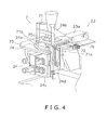
- FIG. 4 is an enlarged perspective view of a former, a former insertion guide assembly and the vertical seal part of the bag-making packaging machine of FIG. 1 .
- FIG. 5 is a perspective view of the former and the former insertion guide assembly coupled to a frame of the bag-making packaging machine showing a state in which a guide main body of the former insertion guide assembly is placed in a former-mounting position.
- FIG. 6 a perspective view of the former, the former insertion guide assembly, and the frame of the bag-making packaging machine showing a state in which the guide main body of the former insertion guide assembly is placed in a former-mounting position.
- FIG. 7 is an enlarged partial front view of the former insertion guide assembly showing a lock mechanism.
- FIGS. 1 and 2 show a vertical bag-making packaging machine 1 according to the illustrated embodiment.
- the bag-making packaging machine 1 is one example of a packaging machine for covering the packaging object (such as potato chips or other foodstuffs) using a film F, and sealing the cylindrically formed film F vertically and laterally to manufacture a bag.
- Predetermined amounts of the packaging object fall into a tube 24a (tubular member) from a weight scale (not shown) disposed above the bag-making packaging machine 1.
- the bag-making packaging machine 1 mainly includes a packaging machine main body 2, a bag-making packaging portion 5 as the main body portion for bagging the packaging object, a film feed portion 6 for feeding to the bag-making packaging portion 5 the film F as the packaging material to be formed into a bag, and a former insertion guide assembly 7 for guiding a later-described former 24b, which forms the film F into a cylindrical shape, when the former 24b is being replaced.
- the bag-making packaging machine 1 is provided with a base foundation 21 and a plurality of functional parts such as an airshaft part 22, a pull-down part 23, a vertical seal part 24, a horizontal or lateral seal part 25, a gear box 26, a pressure unit 27, and a printing unit 28.
- the functional parts are formed into units (modules) to allow these parts to be combined, and the operation of the drive portion of each unit is controlled by a control device (not shown).
- the packaging machine main body 2 is basically a combination of the base foundation 21 and first through fifth frames 41 to 45 that support the above-described functional parts as individual units.
- the plurality of functional parts i.e., the airshaft part 22, the pull-down part 23, the vertical seal part 24, the lateral seal part 25, the gear box 26, the pressure unit 27, and the printing unit 28 are each arranged as a module and supported by one of the first to fifth frames 41 to 45 on the base foundation 21, as shown in FIGS. 1 and 2 .
- the lateral seal part 25 and the gear box 26 are disposed in the second frame 42 located in the forward-most part (left front side of FIG. 1 ) of the packaging machine main body 2 as shown in FIGS. 1 and 4 .
- the vertical seal part 24, the pull-down part 23, and the printing unit 28 are disposed in the third frame 43 located in the upper-most part of the packaging machine main body 2.
- the pressure unit 27 is supported by the second frame 42, the fourth frame 44, and the fifth frame 45.
- the airshaft part 22 is supported by the fifth frame 45.
- the drive motor 29 of the airshaft part 22 shown in FIG. 1 is also supported by the fifth frame 45.
- a film roll Fr on which the film F is wound is set on the airshaft part 22, and the film F is drawn out from the film roll Fr.
- the film F drawn from the film roll Fr is fed by the operation of a drive motor 29 (see FIG. 2 ) for rotating the film roll Fr, and is transported by being pulled to the bag-making packaging portion 5 by the operation of the pull-down part 23.
- the movement of the drive motor 29 and the pull-down part 23 is controlled by the control device.
- the film feed portion 6 has the airshaft part 22 for vacuum chucking and rotatably driving the film roll Fr, and the pull-down part 23 for drawing the film F wound on the film roll Fr toward the vertical seal part 24.
- the pull-down part 23 corresponds to the film transport unit.
- the pull-down part 23 is provided to the packaging machine main body 2 and transports the film F from the rear side (an example of the first end part) towards the front side (an example of the second end part) of the packaging machine main body 2.
- the pull-down part 23 has a chucking belt mechanism 23a, a vacuum pump (not shown) for generating the suction force of the chucking belt mechanism 23a, and a drive unit 23b for rotating the chucking belt.
- the drive unit 23b of the vacuum pump and the chucking belt are disposed in the space inside the first to fifth frames 41 to 45.
- the printing unit 28 prints characters or symbols that show the manufacturing date and other information on the surface of the film F drawn out from the film roll Fr.
- the film feed portion 6 as explained above is a conventional structure that is well known in the art. Since the film feed portion 6 is well known in the art, the structure will not be discussed or illustrated in detail herein. Rather, it will be apparent to those skilled in the art from this disclosure that the film feed portion 6 can be any type of structure that can be used to carry out the present invention.
- the bag-making packaging portion 5 has the vertical seal part 24 for forming the film F into a cylindrical shape and vertically sealing the seam in the vertical direction (the transport direction of the film F), as shown in FIGS. 1 to 3 .
- the bag-making packaging portion 5 also has the lateral seal part 25 for laterally sealing the cylindrically-formed film Fm in the lateral direction (the width direction of the film F) by using a pair of seal jaws 51.
- the gear box 26 and the pressure unit 27 drive the lateral seal part 25 in order to open and close the seal jaws 51 and to perform other operations.
- the bag-making packaging portion 5 as explained above is a conventional structure that is well known in the art except for inclusion of the former insertion guide assembly 7 described in more detail below. Since the bag-making packaging portion 5 is well known in the art, the structure will not be discussed or illustrated in detail herein. Rather, it will be apparent to those skilled in the art from this disclosure that the bag-making packaging portion 5 can be any type of structure that can be used to carry out the present invention.
- the vertical seal part 24 has the tube 24a, the former 24b, a vertical seal heater 24c, and a pull-down roller 24d.
- the tube 24a is a cylindrically shaped member having open upper and lower ends.
- a packaging object C weighed using a weight scale (not shown) disposed in the tube 24a is loaded into the opening at the upper end of the tube 24a.
- the former 24b is a member for forming the film F into a cylindrical shape with directing downwards and is disposed so as to surround the tube 24a.
- the shape of the former 24b is designed to form the sheet-shaped film F as drawn from the film roll Fr into a cylindrical shape when the film F passes between the former 24b and the tube 24a.
- the tube 24a and the former 24b can be replaced in accordance with the size of the bag to be manufactured.
- the vertical seal heater 24c sandwiches the overlapping portion Fs of the cylindrical film Fm wound on the tube 24a and makes a vertical seal from the two sides of the overlapping portion in a state in which the overlapping portion Fs has protruded from the surface of the tube 24a, as shown in FIGS. 3 and 4 .
- the vertical seal heater 24c sandwiches the overlapping portion Fs from the both sides thereof of the cylindrical film Fm and makes a vertical seal, but other methods may be used to make the vertical seal.
- the vertical seal heater 24c may be heated by being pressed against the tube 24a with a constant pressure to form a vertically seal on the overlapping portion of the cylindrical film Fm.
- the lateral seal part 25 is disposed below the vertical seal part 24.
- the lateral seal part 25 is a mechanism that includes a pair of seal jaws 51 that accommodate a heater.
- the lateral seal part 25 has a jaw-rotating motor for rotating the seal jaws 51 so that each of the pair of seal jaws 51 forms a mutually symmetric D-shaped trajectory.
- a cutter (not shown) is accommodated inside one of the seal jaws 51.
- the cutter cuts and separates the bag B and the trailing cylindrical film Fm in a center position in the height direction of the lateral seal portion made by the seal jaws 51.
- the former insertion guide assembly 7 is configured and arranged to guide the former 24b to a predetermined position on the front side of the packaging machine main body 2 while rotating the former 24b on a horizontal plane from the lateral side of the packaging machine main body 2 when the former 24b is mounted to the packaging machine main body 2.
- the former insertion guide assembly 7 has a guide main body 71, a first support unit 72, and a second support unit 73, as shown in FIGS. 4 to 6 .
- the guide main body 71 supports the former 24b.
- the first support unit 72 rotatably and slidably supports a leg part 71a, which is one end (first end section) of the guide main body 71, on the upper surface of the first support unit 72.
- the second support unit 73 has a guide rail 74.
- the guide rail 74 has a generally arcuate pathway for guiding a leg part 71b, which is another end (second end section) of the guide main body 71.
- the guide rail 74 is configured and arranged to guide the leg part 71b along the arcuate pathway while turning the guide main body 71 by approximately 90° between a predetermined former mounting position (see FIG. 5 ) in the packaging machine main body 2 and a predetermined former replacement position (see FIG. 6 ).
- the leg part 71a slides on the upper surface of the first support unit 72 while the leg part 71b is guided by the guide rail 74 and the main body 71 turns approximately 90°.
- the former 24b can be readily mounted because the bag-making packaging machine 1 is provided with the former insertion guide assembly 7 for inserting the former 24b while rotating the former 24b from the lateral side of the packaging machine main body 2.
- the configuration of the former insertion guide assembly 7 as described above makes it possible for the guide main body 71 that supports the former 24b to turn approximately 90° on the horizontal plane along the guide rail 74, and for the guide main body 71 to be readily turned approximately 90° with little effort.
- the former 24b may be secured to the guide main body 71 using various methods as long as the methods make it possible to readily and reliably secure the former 24b to the guide main body 71.
- the former 24b may be secured to the guide main body 71 using screws or bolts, or the like.
- the guide main body 71 has a pair of grip portions 75 that is arranged to be physically gripped by hands of an operator as shown in FIGS. 4-6 .
- the grip portions 75 are disposed in positions near the first support unit 72 and the second support unit 73, respectively. Therefore, the guide main body 71 can be readily turned approximately 90° with little effort while the operator holds the grip portions 75.
- the guide main body 71 further supports the tube 24a as well as the former 24b. Therefore, the tube 24a can rotate together with the former 24b to make it even easier to replace the former 24b.
- the former insertion guide assembly 7 has a lock mechanism 76 that selectively restricts and releases the rotation of the guide main body 71 with respect to the packaging machine main body 2.
- the lock mechanism 76 has a block 76a that fits onto a flange part 71c formed on a side surface of the leg part 71a of the guide main body 71, a support portion 76b for reciprocatingly supporting the block 76a, a cylinder 76c for pressing the block 76a toward the flange part 71c of the guide main body 71, and a handle 76d for causing the cylinder 76c to move in a reciprocating manner.
- the guide main body 71 can be reliably locked with a simple operation.
- the guide main body 71 can thereby be locked by the lock mechanism 76 so that the guide main body 71 does not move in a state in which the guide main body 71 is set in a predetermined former mounting position (see FIG. 5 ) in the packaging machine main body 2. Also, since the guide main body 71 is allowed to move by releasing the lock mechanism 76 during former replacement, the guide main body 71 can be rotatably moved and the former 24b can be readily replaced.
- the lock mechanism 76 is configured so as to be easily operated and capable of preventing erroneous operation, such as tilting the handle 76d in one direction to achieve a locked state, and tilting the handle 76d in another direction to achieve a released state.
- the former insertion guide assembly 7 guides the former 24b to a predetermined position on the front side of the packaging machine main body 2 while rotating the former 24b from the lateral direction of the packaging machine main body 2.
- the former 24b can thus be mounted easily in a simple manner because the bag-making packaging machine 1 is provided with a former insertion guide assembly 7 that inserts the former 24b while rotating the former 24b from the lateral direction of the packaging machine main body 2. Also, the former 24b can be automatically loaded or mounted if an automatic mounting mechanism is provided to the side of the bag-making packaging machine 1 in order to mount a plurality of formers 24b that correspond to the bag sizes.
- the former 24b can be slidably inserted from the lateral direction by using the former insertion guide assembly 7, as shown in FIGS. 5 to 6 .
- the former insertion guide assembly 7 is first mounted in the lateral direction and is then rotated while being pressed inward, whereby the former 24b is mounted. Therefore, the mounting can be carried out with little effort in a simple manner even by a person of average physical abilities, i.e. a woman or the like.
- a former rack can be disposed to the side of the bag-making packaging machine 1 since mounting from the lateral direction is possible, and automatic mounting of the former 24b, which has heretofore been impossible, can be carried out in the manner of an automatic tool switching mechanism of a machining center.
- the configuration can be made more user friendly in that the labor of replacing the former 24b can be considerably reduced by using the former insertion guide assembly 7 in the manner described above.
- the work of mounting the former 24b can be carried out over a short movement distance.
- the work of replacing the former 24b from the front direction of the packaging machine main body 2 is difficult and involves heavy labor because a mechanism such as a vertical seal heater 24c, or a rising conveyor is disposed in the front area of the former 24b and the tube 24a.
- the former 24b and the former insertion guide assembly 7 are merely first rotated in the lateral direction inside the packaging machine main body 2. Therefore, the work of mounting the former 24b from the lateral direction of the packaging machine main body 2 can be carried out in a simple manner without any interference from obstacles (a mechanism such as the vertical seal heater 24c, or a rising conveyor or the like) in front of the packaging machine main body 2.
- the former insertion guide assembly 7 has the guide main body 71, the first support unit 72, and the second support unit 73 according to one specific configuration.
- the guide main body 71 supports the former 24b.
- the first support unit 72 rotatably supports one end part of the guide main body 71.
- the second support unit 73 has a guide rail 74.
- the guide rail 74 has an arcuate pathway and guides the other end part of the guide main body 71 along the arcuate pathway while turning the other end part by approximately 90° between a predetermined former mounting position (see FIG. 5 ) in the packaging machine main body 2 and a predetermined former replacement position (see FIG. 6 ).
- the former insertion guide assembly 7 is configured to turn the guide main body 71, which supports the former 24b, by approximately 90° along the guide rail 74, whereby the guide main body 71, which supports the former 24b, can be readily turned approximately 90° with little effort while being supported by the first support unit 72 and the second support unit 73.
- the guide main body 71 has a pair of grip portions 75disposed in positions near the first support unit 72 and the second support unit 73, respectively.
- the grip portions 75 are configured and arranged to be gripped by hands of an operator.
- the guide main body 71 can thereby be readily turned approximately 90° with little effort using the pair of grip portions 75.
- the guide main body 71 supports the tube 24a in addition to the former 24b.
- the tube 24a can also be rotated approximately 90° together with the former 24b, and replacement of the former 24b is therefore further facilitated.
- the replacement work can be readily carried out even when the tube 24a and the former 24b are both replaced.
- the former insertion guide assembly 7 has a lock mechanism 76 for selectively restricting the rotation of the guide main body 71 with respect to the first and second support units 72 and 73 and releasing the restriction. Therefore, the guide main body 71 can thereby be locked by the lock mechanism 76 so as to be prevented from moving in a state in which the guide main body 71 is set in the predetermined former mounting position (see FIG. 5 ) in the packaging machine main body 2. Also, the guide main body 71 can be rotatably moved and the former 24b can be readily replaced by releasing the lock mechanism 76 when the former 24b is replaced.
- the illustrated embodiment can be applied to a packaging machine in which the former is required to be replaced.
- the term “comprising” and its derivatives, as used herein, are intended to be open ended terms that specify the presence of the stated features, elements, components, groups, integers, and/or steps, but do not exclude the presence of other unstated features, elements, components, groups, integers and/or steps.
- the foregoing also applies to words having similar meanings such as the terms, “including”, “having” and their derivatives.
- the terms “part,” “section,” “portion,” “member” or “element” when used in the singular can have the dual meaning of a single part or a plurality of parts.
- the terms of degree such as “substantially”, “about” and “approximately” as used herein mean a reasonable amount of deviation of the modified term such that the end result is not significantly changed.
Landscapes
- Engineering & Computer Science (AREA)
- Mechanical Engineering (AREA)
- Containers And Plastic Fillers For Packaging (AREA)
- Auxiliary Devices For And Details Of Packaging Control (AREA)
Abstract
Description
- This application claims priority to Japanese Patent Application No.
2008-135385, filed on May 23, 2008 2008-135385 - The present invention relates to a packaging machine.
- Automatic packaging machines and various other packaging machines have conventionally been proposed in which a strip-shaped film is continuously molded into a cylindrical shape using a former, and the cylindrical film is first sealed vertically and then horizontally, whereby content-filled bags are automatically manufactured, as shown in Japanese Laid-Open Patent Application No.
2005-41576 - With a conventional packaging machine, an operator manually pulls the former and the support portion with his hand when the former is replaced, whereby the former and the support portion are moved forward or laterally in a straight line from the main body and are separated from the main body, whereupon the former is replaced.
- In view of the above, it will be apparent to those skilled in the art from this disclosure that there exists a need for an improved former mounting arrangement. This invention addresses this need in the art as well as other needs, which will become apparent to those skilled in the art from this disclosure.
- Conventionally, the former is made of steel or an alloy or the like having high strength and dimensional accuracy, and is a very heavy object ordinarily having a weight of about 30 kg. The film roll is wound with several hundred meters of strip-shaped film, and therefore ordinarily weighs about 40 kg. In the packaging industry of foodstuffs and the like in particular, there are cases in which about 50 multifarious types of bag sizes are used, and the work of replacing the former for changing sizes during the film replacement or the like requires considerable labor.
- The former can be inserted into the packaging machine from the front of the packaging machine main body, providing so-called front access. When inserted in this direction, an operator must replace the former the former by twisting his body or using another uncomfortable posture because there is usually no space for the operator to stand due to the structural parts provided to a lower part of the packaging machine, such as a rising conveyor. Also, the packaging machine ordinarily has an erectly disposed tubular member or a tube that, together with the former, forms the film into a cylindrical shape and guides the cylindrical film downwards. However, when twin piping is used in which a plurality of tubes is arranged in a line, the workspace for replacing the former is further reduced.
- In a case in which the former is rectilinearly moved and drawn out in the lateral direction of the packaging machine, as in the conventional packaging machine described in Japanese Laid-open Patent Application No.
2005-41576 - An object of the present invention is to provide a packaging machine in which the former can be replaced easily.
- A packaging machine according to a first aspect of the present invention includes a packaging machine main body, a film transport unit, a former and a former insertion guide assembly. The film transport unit is coupled to the packaging main body, and configured and arranged to transport a film as a packaging material from a first end part of the packaging main body towards a second end part of the packaging main body opposite from the first end part. The former is disposed in the second end part of the packaging main body, and configured and arranged to form the film transported by the film transport unit into a cylindrical shape and to direct the film downwards. The former insertion guide assembly is configured and arranged to guide the former to a predetermined position in the second end part of the packaging machine main body while the former is rotated from a lateral side of the packaging machine main body when the former is mounted to the packaging machine main body.
- These and other objects, features, aspects and advantages of the present invention will become apparent to those skilled in the art from the following detailed description, which, taken in conjunction with the annexed drawings, discloses a preferred embodiment of the present invention.
- Referring now to the attached drawings which form a part of this original disclosure:
-
FIG. 1 is an overall front perspective view of a bag-making packaging machine according to an embodiment of the present invention. -
FIG. 2 is a side perspective view of the bag-making packaging machine ofFIG. 1 . -
FIG. 3 is a schematic view of a vertical seal part and a lateral seal part of the bag-making packaging machine ofFIG.1 . -
FIG. 4 is an enlarged perspective view of a former, a former insertion guide assembly and the vertical seal part of the bag-making packaging machine ofFIG. 1 . -
FIG. 5 is a perspective view of the former and the former insertion guide assembly coupled to a frame of the bag-making packaging machine showing a state in which a guide main body of the former insertion guide assembly is placed in a former-mounting position. -
FIG. 6 a perspective view of the former, the former insertion guide assembly, and the frame of the bag-making packaging machine showing a state in which the guide main body of the former insertion guide assembly is placed in a former-mounting position. -
FIG. 7 is an enlarged partial front view of the former insertion guide assembly showing a lock mechanism. - Selected embodiment of the present invention will now be explained with reference to the drawings. It will be apparent to those skilled in the art from this disclosure that the following description of the embodiment of the present invention is provided for illustration only and not for the purpose of limiting the invention as defined by the appended claims and their equivalents.
-
FIGS. 1 and2 show a vertical bag-making packaging machine 1 according to the illustrated embodiment. The bag-making packaging machine 1 is one example of a packaging machine for covering the packaging object (such as potato chips or other foodstuffs) using a film F, and sealing the cylindrically formed film F vertically and laterally to manufacture a bag. - Predetermined amounts of the packaging object fall into a
tube 24a (tubular member) from a weight scale (not shown) disposed above the bag-making packaging machine 1. - The bag-making packaging machine 1 mainly includes a packaging machine
main body 2, a bag-makingpackaging portion 5 as the main body portion for bagging the packaging object, afilm feed portion 6 for feeding to the bag-makingpackaging portion 5 the film F as the packaging material to be formed into a bag, and a formerinsertion guide assembly 7 for guiding a later-described former 24b, which forms the film F into a cylindrical shape, when the former 24b is being replaced. - Specifically, the bag-making packaging machine 1 is provided with a
base foundation 21 and a plurality of functional parts such as anairshaft part 22, a pull-down part 23, avertical seal part 24, a horizontal orlateral seal part 25, agear box 26, apressure unit 27, and aprinting unit 28. The functional parts are formed into units (modules) to allow these parts to be combined, and the operation of the drive portion of each unit is controlled by a control device (not shown). - The packaging machine
main body 2 is basically a combination of thebase foundation 21 and first throughfifth frames 41 to 45 that support the above-described functional parts as individual units. - The plurality of functional parts, i.e., the
airshaft part 22, the pull-downpart 23, thevertical seal part 24, thelateral seal part 25, thegear box 26, thepressure unit 27, and theprinting unit 28 are each arranged as a module and supported by one of the first tofifth frames 41 to 45 on thebase foundation 21, as shown inFIGS. 1 and2 . - The
lateral seal part 25 and thegear box 26 are disposed in thesecond frame 42 located in the forward-most part (left front side ofFIG. 1 ) of the packaging machinemain body 2 as shown inFIGS. 1 and4 . Thevertical seal part 24, the pull-downpart 23, and theprinting unit 28 are disposed in thethird frame 43 located in the upper-most part of the packaging machinemain body 2. Thepressure unit 27 is supported by thesecond frame 42, thefourth frame 44, and thefifth frame 45. Theairshaft part 22 is supported by thefifth frame 45. Thedrive motor 29 of theairshaft part 22 shown inFIG. 1 is also supported by thefifth frame 45. - In the
film feed portion 6, a film roll Fr on which the film F is wound is set on theairshaft part 22, and the film F is drawn out from the film roll Fr. - The film F drawn from the film roll Fr is fed by the operation of a drive motor 29 (see
FIG. 2 ) for rotating the film roll Fr, and is transported by being pulled to the bag-makingpackaging portion 5 by the operation of the pull-downpart 23. The movement of thedrive motor 29 and the pull-downpart 23 is controlled by the control device. - Specifically, the
film feed portion 6 has theairshaft part 22 for vacuum chucking and rotatably driving the film roll Fr, and the pull-downpart 23 for drawing the film F wound on the film roll Fr toward thevertical seal part 24. The pull-downpart 23 corresponds to the film transport unit. In other words, the pull-downpart 23 is provided to the packaging machinemain body 2 and transports the film F from the rear side (an example of the first end part) towards the front side (an example of the second end part) of the packaging machinemain body 2. - The pull-
down part 23 has achucking belt mechanism 23a, a vacuum pump (not shown) for generating the suction force of thechucking belt mechanism 23a, and adrive unit 23b for rotating the chucking belt. Thedrive unit 23b of the vacuum pump and the chucking belt are disposed in the space inside the first tofifth frames 41 to 45. - The
printing unit 28 prints characters or symbols that show the manufacturing date and other information on the surface of the film F drawn out from the film roll Fr. - The
film feed portion 6 as explained above is a conventional structure that is well known in the art. Since thefilm feed portion 6 is well known in the art, the structure will not be discussed or illustrated in detail herein. Rather, it will be apparent to those skilled in the art from this disclosure that thefilm feed portion 6 can be any type of structure that can be used to carry out the present invention. - The bag-making
packaging portion 5 has thevertical seal part 24 for forming the film F into a cylindrical shape and vertically sealing the seam in the vertical direction (the transport direction of the film F), as shown inFIGS. 1 to 3 . The bag-makingpackaging portion 5 also has thelateral seal part 25 for laterally sealing the cylindrically-formed film Fm in the lateral direction (the width direction of the film F) by using a pair ofseal jaws 51. Thegear box 26 and thepressure unit 27 drive thelateral seal part 25 in order to open and close theseal jaws 51 and to perform other operations. - The bag-making
packaging portion 5 as explained above is a conventional structure that is well known in the art except for inclusion of the formerinsertion guide assembly 7 described in more detail below. Since the bag-makingpackaging portion 5 is well known in the art, the structure will not be discussed or illustrated in detail herein. Rather, it will be apparent to those skilled in the art from this disclosure that the bag-makingpackaging portion 5 can be any type of structure that can be used to carry out the present invention.
Vertical Seal Part 24 - The
vertical seal part 24 has thetube 24a, the former 24b, avertical seal heater 24c, and a pull-downroller 24d. Thetube 24a is a cylindrically shaped member having open upper and lower ends. A packaging object C weighed using a weight scale (not shown) disposed in thetube 24a is loaded into the opening at the upper end of thetube 24a. - The former 24b is a member for forming the film F into a cylindrical shape with directing downwards and is disposed so as to surround the
tube 24a. The shape of the former 24b is designed to form the sheet-shaped film F as drawn from the film roll Fr into a cylindrical shape when the film F passes between the former 24b and thetube 24a. Thetube 24a and the former 24b can be replaced in accordance with the size of the bag to be manufactured. - The
vertical seal heater 24c sandwiches the overlapping portion Fs of the cylindrical film Fm wound on thetube 24a and makes a vertical seal from the two sides of the overlapping portion in a state in which the overlapping portion Fs has protruded from the surface of thetube 24a, as shown inFIGS. 3 and4 . - In the present embodiment, the
vertical seal heater 24c sandwiches the overlapping portion Fs from the both sides thereof of the cylindrical film Fm and makes a vertical seal, but other methods may be used to make the vertical seal. For example, thevertical seal heater 24c may be heated by being pressed against thetube 24a with a constant pressure to form a vertically seal on the overlapping portion of the cylindrical film Fm. - The
lateral seal part 25 is disposed below thevertical seal part 24. Thelateral seal part 25 is a mechanism that includes a pair ofseal jaws 51 that accommodate a heater. - Although not shown in
FIG. 3 , thelateral seal part 25 has a jaw-rotating motor for rotating theseal jaws 51 so that each of the pair ofseal jaws 51 forms a mutually symmetric D-shaped trajectory. - A cutter (not shown) is accommodated inside one of the
seal jaws 51. The cutter cuts and separates the bag B and the trailing cylindrical film Fm in a center position in the height direction of the lateral seal portion made by theseal jaws 51. - The former
insertion guide assembly 7 is configured and arranged to guide the former 24b to a predetermined position on the front side of the packaging machinemain body 2 while rotating the former 24b on a horizontal plane from the lateral side of the packaging machinemain body 2 when the former 24b is mounted to the packaging machinemain body 2. - Specifically, the former
insertion guide assembly 7 has a guidemain body 71, afirst support unit 72, and asecond support unit 73, as shown inFIGS. 4 to 6 . The guidemain body 71 supports the former 24b. Thefirst support unit 72 rotatably and slidably supports aleg part 71a, which is one end (first end section) of the guidemain body 71, on the upper surface of thefirst support unit 72. Thesecond support unit 73 has aguide rail 74. Theguide rail 74 has a generally arcuate pathway for guiding aleg part 71b, which is another end (second end section) of the guidemain body 71. Theguide rail 74 is configured and arranged to guide theleg part 71b along the arcuate pathway while turning the guidemain body 71 by approximately 90° between a predetermined former mounting position (seeFIG. 5 ) in the packaging machinemain body 2 and a predetermined former replacement position (seeFIG. 6 ). Theleg part 71a slides on the upper surface of thefirst support unit 72 while theleg part 71b is guided by theguide rail 74 and themain body 71 turns approximately 90°. - In this manner, the former 24b can be readily mounted because the bag-making packaging machine 1 is provided with the former
insertion guide assembly 7 for inserting the former 24b while rotating the former 24b from the lateral side of the packaging machinemain body 2. - Also, the configuration of the former
insertion guide assembly 7 as described above makes it possible for the guidemain body 71 that supports the former 24b to turn approximately 90° on the horizontal plane along theguide rail 74, and for the guidemain body 71 to be readily turned approximately 90° with little effort. - The former 24b may be secured to the guide
main body 71 using various methods as long as the methods make it possible to readily and reliably secure the former 24b to the guidemain body 71. For example, the former 24b may be secured to the guidemain body 71 using screws or bolts, or the like. - The guide
main body 71 has a pair ofgrip portions 75 that is arranged to be physically gripped by hands of an operator as shown inFIGS. 4-6 . Thegrip portions 75 are disposed in positions near thefirst support unit 72 and thesecond support unit 73, respectively. Therefore, the guidemain body 71 can be readily turned approximately 90° with little effort while the operator holds thegrip portions 75. - The guide
main body 71 further supports thetube 24a as well as the former 24b. Therefore, thetube 24a can rotate together with the former 24b to make it even easier to replace the former 24b. - The former
insertion guide assembly 7 has alock mechanism 76 that selectively restricts and releases the rotation of the guidemain body 71 with respect to the packaging machinemain body 2. - More specifically, as shown in
FIGS. 5 to 7 , thelock mechanism 76 has ablock 76a that fits onto aflange part 71c formed on a side surface of theleg part 71a of the guidemain body 71, asupport portion 76b for reciprocatingly supporting theblock 76a, acylinder 76c for pressing theblock 76a toward theflange part 71c of the guidemain body 71, and ahandle 76d for causing thecylinder 76c to move in a reciprocating manner. - Therefore, when an operator operates the
handle 76d to press theblock 76a against theflange part 71c of the guidemain body 71 via thecylinder 76c, the guidemain body 71 can be reliably locked with a simple operation. - The guide
main body 71 can thereby be locked by thelock mechanism 76 so that the guidemain body 71 does not move in a state in which the guidemain body 71 is set in a predetermined former mounting position (seeFIG. 5 ) in the packaging machinemain body 2. Also, since the guidemain body 71 is allowed to move by releasing thelock mechanism 76 during former replacement, the guidemain body 71 can be rotatably moved and the former 24b can be readily replaced. - The
lock mechanism 76 is configured so as to be easily operated and capable of preventing erroneous operation, such as tilting thehandle 76d in one direction to achieve a locked state, and tilting thehandle 76d in another direction to achieve a released state. - (1) With the bag-making packaging machine 1 of the embodiment, the former
insertion guide assembly 7 guides the former 24b to a predetermined position on the front side of the packaging machinemain body 2 while rotating the former 24b from the lateral direction of the packaging machinemain body 2. - The former 24b can thus be mounted easily in a simple manner because the bag-making packaging machine 1 is provided with a former
insertion guide assembly 7 that inserts the former 24b while rotating the former 24b from the lateral direction of the packaging machinemain body 2. Also, the former 24b can be automatically loaded or mounted if an automatic mounting mechanism is provided to the side of the bag-making packaging machine 1 in order to mount a plurality offormers 24b that correspond to the bag sizes. - (2) The former 24b can be slidably inserted from the lateral direction by using the former
insertion guide assembly 7, as shown inFIGS. 5 to 6 . For example, the formerinsertion guide assembly 7 is first mounted in the lateral direction and is then rotated while being pressed inward, whereby the former 24b is mounted. Therefore, the mounting can be carried out with little effort in a simple manner even by a person of average physical abilities, i.e. a woman or the like. - A former rack can be disposed to the side of the bag-making packaging machine 1 since mounting from the lateral direction is possible, and automatic mounting of the former 24b, which has heretofore been impossible, can be carried out in the manner of an automatic tool switching mechanism of a machining center.
- Therefore, the configuration can be made more user friendly in that the labor of replacing the former 24b can be considerably reduced by using the former
insertion guide assembly 7 in the manner described above. - (3) In particular, with a lateral slide scheme in which the former and portions that support the former are moved in a rectilinearly reciprocating fashion in the lateral direction of the packaging machine main body as in Japanese Laid-Open Patent Application No.
2005-41576 insertion guide assembly 7 are first rotated in the lateral direction inside the packaging machinemain body 2 in the manner of the bag-making packaging machine 1 of the present embodiment, the work of mounting the former 24b can be carried out over a short movement distance. - (4) With a common automatic packaging machine, the work of replacing the former 24b from the front direction of the packaging machine
main body 2 is difficult and involves heavy labor because a mechanism such as avertical seal heater 24c, or a rising conveyor is disposed in the front area of the former 24b and thetube 24a. However, with the bag-making packaging machine 1 of the present embodiment, the former 24b and the formerinsertion guide assembly 7 are merely first rotated in the lateral direction inside the packaging machinemain body 2. Therefore, the work of mounting the former 24b from the lateral direction of the packaging machinemain body 2 can be carried out in a simple manner without any interference from obstacles (a mechanism such as thevertical seal heater 24c, or a rising conveyor or the like) in front of the packaging machinemain body 2. - (5) With the bag-making packaging machine 1 of the embodiment, the former
insertion guide assembly 7 has the guidemain body 71, thefirst support unit 72, and thesecond support unit 73 according to one specific configuration. The guidemain body 71 supports the former 24b. Thefirst support unit 72 rotatably supports one end part of the guidemain body 71. Thesecond support unit 73 has aguide rail 74. Theguide rail 74 has an arcuate pathway and guides the other end part of the guidemain body 71 along the arcuate pathway while turning the other end part by approximately 90° between a predetermined former mounting position (seeFIG. 5 ) in the packaging machinemain body 2 and a predetermined former replacement position (seeFIG. 6 ). - The former
insertion guide assembly 7 is configured to turn the guidemain body 71, which supports the former 24b, by approximately 90° along theguide rail 74, whereby the guidemain body 71, which supports the former 24b, can be readily turned approximately 90° with little effort while being supported by thefirst support unit 72 and thesecond support unit 73. - (6) In the bag-making packaging machine 1 of the embodiment, the guide
main body 71 has a pair of grip portions 75disposed in positions near thefirst support unit 72 and thesecond support unit 73, respectively. Thegrip portions 75 are configured and arranged to be gripped by hands of an operator. The guidemain body 71 can thereby be readily turned approximately 90° with little effort using the pair ofgrip portions 75. - (7) With the bag-making packaging machine 1 of the embodiment, the guide
main body 71 supports thetube 24a in addition to the former 24b. Thetube 24a can also be rotated approximately 90° together with the former 24b, and replacement of the former 24b is therefore further facilitated. The replacement work can be readily carried out even when thetube 24a and the former 24b are both replaced. - (8) With the bag-making packaging machine 1 of the embodiment, the former
insertion guide assembly 7 has alock mechanism 76 for selectively restricting the rotation of the guidemain body 71 with respect to the first andsecond support units main body 71 can thereby be locked by thelock mechanism 76 so as to be prevented from moving in a state in which the guidemain body 71 is set in the predetermined former mounting position (seeFIG. 5 ) in the packaging machinemain body 2. Also, the guidemain body 71 can be rotatably moved and the former 24b can be readily replaced by releasing thelock mechanism 76 when the former 24b is replaced. - The illustrated embodiment can be applied to a packaging machine in which the former is required to be replaced.
- In understanding the scope of the present invention, the term "comprising" and its derivatives, as used herein, are intended to be open ended terms that specify the presence of the stated features, elements, components, groups, integers, and/or steps, but do not exclude the presence of other unstated features, elements, components, groups, integers and/or steps. The foregoing also applies to words having similar meanings such as the terms, "including", "having" and their derivatives. Also, the terms "part," "section," "portion," "member" or "element" when used in the singular can have the dual meaning of a single part or a plurality of parts. The terms of degree such as "substantially", "about" and "approximately" as used herein mean a reasonable amount of deviation of the modified term such that the end result is not significantly changed.
- While only selected embodiment has been chosen to illustrate the present invention, it will be apparent to those skilled in the art from this disclosure that various changes and modifications can be made herein without departing from the scope of the invention as defined in the appended claims. For example, the size, shape, location or orientation of the various components can be changed as needed and/or desired. Components that are shown directly connected or contacting each other can have intermediate structures disposed between them. The functions of one element can be performed by two, and vice versa. The structures and functions of one embodiment can be adopted in another embodiment. It is not necessary for all advantages to be present in a particular embodiment at the same time. Every feature which is unique from the prior art, alone or in combination with other features, also should be considered a separate description of further inventions by the applicant, including the structural and/or functional concepts embodied by such feature(s). Thus, the foregoing description of the embodiment according to the present invention is provided for illustration only, and not for the purpose of limiting the invention as defined by the appended claims and their equivalents.
Claims (5)
- A packaging machine comprising:a packaging machine main body;a film transport unit coupled to the packaging main body, and configured and arranged to transport a film as a packaging material from a first end part of the packaging main body towards a second end part of the packaging main body opposite from the first end part;a former disposed in the second end part of the packaging main body, and configured and arranged to form the film transported by the film transport unit into a cylindrical shape and to direct the film downwards; anda former insertion guide assembly configured and arranged to guide the former to a predetermined position in the second end part of the packaging machine main body while the former is rotated from a lateral side of the packaging machine main body when the former is mounted to the packaging machine main body.
- The packaging machine according to claim 1, wherein
the former insertion guide assembly havinga guide main body supporting the former,a first support unit configured and arranged to rotatably support a first end section of the guide main body, anda second support unit having a guide rail configured and arranged to guide a second end section of the guide main body along a generally arcuate pathway while turning the guide main body by approximately 90° between a predetermined former mounting position in the packaging machine main body and a predetermined former replacement position. - The packaging machine according to claim 2, wherein
the guide main body includes a pair of grip portions disposed adjacent to the first support unit and the second support unit, respectively, and configured and arranged to be gripped by hands of an operator. - The packaging machine according to any one of claims 2 to 3, further comprising
a tubular member configured and arranged to cylindrically mold the film together with the former,
the guide main body further supporting the tubular member. - The packaging machine according any one of claims 2 to 4, wherein
the former insertion guide assembly further has a lock mechanism configured and arranged to selectively restrict a rotation of the guide main body with respect to the first and second support units.
Applications Claiming Priority (1)
| Application Number | Priority Date | Filing Date | Title |
|---|---|---|---|
| JP2008135385A JP5133777B2 (en) | 2008-05-23 | 2008-05-23 | Packaging machine |
Publications (3)
| Publication Number | Publication Date |
|---|---|
| EP2128028A2 true EP2128028A2 (en) | 2009-12-02 |
| EP2128028A3 EP2128028A3 (en) | 2011-11-30 |
| EP2128028B1 EP2128028B1 (en) | 2013-04-10 |
Family
ID=40888072
Family Applications (1)
| Application Number | Title | Priority Date | Filing Date |
|---|---|---|---|
| EP09160688.9A Not-in-force EP2128028B1 (en) | 2008-05-23 | 2009-05-19 | Packaging machine |
Country Status (4)
| Country | Link |
|---|---|
| US (1) | US8522516B2 (en) |
| EP (1) | EP2128028B1 (en) |
| JP (1) | JP5133777B2 (en) |
| CN (1) | CN101585417B (en) |
Cited By (4)
| Publication number | Priority date | Publication date | Assignee | Title |
|---|---|---|---|---|
| WO2012145757A1 (en) * | 2011-04-21 | 2012-10-26 | J & F Business, Inc. | Bag former assembly |
| EP2998231A1 (en) * | 2014-09-19 | 2016-03-23 | Mespack, S.L. | Metering head support device for a container forming, filling and sealing machine |
| EP3424829A1 (en) | 2017-07-07 | 2019-01-09 | Ulma Packaging Technological Center, S. Coop | Vertical packaging machine |
| IT201900005974A1 (en) * | 2019-04-17 | 2020-10-17 | Messersi Packaging Srl | Strapping station with rotatable strapping unit |
Families Citing this family (14)
| Publication number | Priority date | Publication date | Assignee | Title |
|---|---|---|---|---|
| JP5749939B2 (en) * | 2011-03-02 | 2015-07-15 | 株式会社イシダ | Bag making and packaging machine |
| AU2012201494B2 (en) * | 2011-03-17 | 2016-12-01 | Tna Australia Pty Limited | A packaging machine former |
| JP5528409B2 (en) * | 2011-10-17 | 2014-06-25 | 株式会社フジキカイ | Sealing device for bag making and filling machine |
| JP2013230842A (en) * | 2012-04-27 | 2013-11-14 | Ishida Co Ltd | Bag-making and packaging machine |
| CN103224047A (en) * | 2013-05-17 | 2013-07-31 | 海宁市金跃印务有限公司 | Film folding device of film packing machine |
| ES1135355Y (en) | 2014-12-18 | 2015-04-13 | Ulma Packaging Technological Ct S Coop | Vertical packing machine |
| JP6765785B2 (en) * | 2015-03-19 | 2020-10-07 | 株式会社イシダ | Bag making and packaging machine |
| CN106081202A (en) * | 2016-06-07 | 2016-11-09 | 苏州杰悦五金机械有限公司 | A kind of food factory special for automatic packing machine |
| EP3514074A4 (en) * | 2016-09-16 | 2019-07-31 | Ishida Co., Ltd. | WEIGHING / PACKING DEVICE |
| US10604283B2 (en) * | 2017-05-26 | 2020-03-31 | Frito-Lay North America, Inc. | Former assembly with improved center of gravity |
| CN110683139A (en) * | 2019-10-11 | 2020-01-14 | 广州三木汽车部件有限公司 | Automobile interior part packaging machine |
| EP3825240B1 (en) * | 2019-11-25 | 2021-08-18 | Ulma Packaging Technological Center, S.Coop. | Packaging machine for generating reclosable packages |
| JP2024036106A (en) * | 2022-09-05 | 2024-03-15 | 株式会社イシダ | Goods filling equipment |
| NL2036252B1 (en) | 2023-11-13 | 2025-05-23 | Jasa Group B V | Vertical packaging machine, cutting assembly for a vertical packaging machine and a method for changing a forming set on a vertical packaging machine |
Citations (1)
| Publication number | Priority date | Publication date | Assignee | Title |
|---|---|---|---|---|
| JP2005041576A (en) | 2003-07-08 | 2005-02-17 | Tna Australia Pty Ltd | Packing machine former support |
Family Cites Families (12)
| Publication number | Priority date | Publication date | Assignee | Title |
|---|---|---|---|---|
| DE1296074B (en) * | 1965-07-01 | 1969-05-22 | Otto Dr Ing | Machine for the production of pouch packs |
| ES361291A1 (en) * | 1967-12-14 | 1970-11-01 | Vnh Gebr Aquarius Nv Maschf | Apparatus for folding a laminated material in a tube. (Machine-translation by Google Translate, not legally binding) |
| JP3393553B2 (en) * | 1992-07-10 | 2003-04-07 | 株式会社イシダ | Bag making and packaging machine |
| US6131367A (en) * | 1998-05-11 | 2000-10-17 | Ishida Co., Ltd. | Packaging machine with improved former unit attachment |
| JP4278775B2 (en) * | 1998-05-11 | 2009-06-17 | 株式会社イシダ | Bag making and packaging machine |
| US6722106B2 (en) * | 2002-03-18 | 2004-04-20 | Recot, Inc. | Vertical stand-up pouch |
| JP3964730B2 (en) * | 2002-05-02 | 2007-08-22 | 株式会社湯山製作所 | Drug packaging device |
| JP2004149145A (en) * | 2002-10-30 | 2004-05-27 | Nippon Seiki Co Ltd | Filling and packaging machine |
| MXPA04012837A (en) * | 2004-01-06 | 2005-07-07 | Tna Australia Pty Ltd | A packaging machine and former. |
| JP2008094456A (en) * | 2006-10-13 | 2008-04-24 | Ishida Co Ltd | Vertical seal mechanism |
| US7523597B2 (en) * | 2007-03-20 | 2009-04-28 | J & F Business, Inc. | Apparatus and method for mounting a bag former |
| JP5000362B2 (en) * | 2007-04-06 | 2012-08-15 | 株式会社イシダ | Bag making and packaging machine |
-
2008
- 2008-05-23 JP JP2008135385A patent/JP5133777B2/en not_active Expired - Fee Related
-
2009
- 2009-05-15 US US12/466,703 patent/US8522516B2/en not_active Expired - Fee Related
- 2009-05-19 EP EP09160688.9A patent/EP2128028B1/en not_active Not-in-force
- 2009-05-22 CN CN200910143027.5A patent/CN101585417B/en not_active Expired - Fee Related
Patent Citations (1)
| Publication number | Priority date | Publication date | Assignee | Title |
|---|---|---|---|---|
| JP2005041576A (en) | 2003-07-08 | 2005-02-17 | Tna Australia Pty Ltd | Packing machine former support |
Cited By (7)
| Publication number | Priority date | Publication date | Assignee | Title |
|---|---|---|---|---|
| WO2012145757A1 (en) * | 2011-04-21 | 2012-10-26 | J & F Business, Inc. | Bag former assembly |
| US9463886B2 (en) | 2011-04-21 | 2016-10-11 | J & F Business, Inc. | Bag former assembly |
| EP2998231A1 (en) * | 2014-09-19 | 2016-03-23 | Mespack, S.L. | Metering head support device for a container forming, filling and sealing machine |
| EP3424829A1 (en) | 2017-07-07 | 2019-01-09 | Ulma Packaging Technological Center, S. Coop | Vertical packaging machine |
| US10946998B2 (en) | 2017-07-07 | 2021-03-16 | Ulma Packaging Technological Center, S. Coop. | Vertical packaging machine |
| IT201900005974A1 (en) * | 2019-04-17 | 2020-10-17 | Messersi Packaging Srl | Strapping station with rotatable strapping unit |
| WO2020212888A1 (en) * | 2019-04-17 | 2020-10-22 | Messersi' Packaging S.R.L. | Strapping station with rotatable strapping unit |
Also Published As
| Publication number | Publication date |
|---|---|
| US20090288376A1 (en) | 2009-11-26 |
| EP2128028B1 (en) | 2013-04-10 |
| EP2128028A3 (en) | 2011-11-30 |
| CN101585417A (en) | 2009-11-25 |
| US8522516B2 (en) | 2013-09-03 |
| JP2009280256A (en) | 2009-12-03 |
| JP5133777B2 (en) | 2013-01-30 |
| CN101585417B (en) | 2010-12-08 |
Similar Documents
| Publication | Publication Date | Title |
|---|---|---|
| EP2128028B1 (en) | Packaging machine | |
| KR20140133439A (en) | Gas-filling packaging method and packaging machine therefor | |
| CN210314761U (en) | Feeding, folding and cutting device and automatic shoe tongue and ear folding and sewing equipment comprising same | |
| CN110077663B (en) | Suture automatic packaging machine | |
| CN109353597B (en) | Barrel film packaging machine | |
| EP1020365B1 (en) | An automatic machine for processing items of the tobacco industry | |
| JP7097595B2 (en) | Bag making filling and packaging machine | |
| JP5229659B2 (en) | Sheet feeding apparatus and sheet packaging machine using the same | |
| JP5220476B2 (en) | Packaging machine | |
| JP6574330B2 (en) | Bag making and packaging machine | |
| JP2023533101A5 (en) | ||
| CN112319904A (en) | A sock pocket machine | |
| CN106829009A (en) | The banding of full-automatic horizontal four abnormity packing machine | |
| CN215551339U (en) | Bagging production equipment | |
| JP2009073050A (en) | Bookbinding equipment | |
| KR20190112665A (en) | Filling and packaging machine | |
| JP7498570B2 (en) | Bag making and filling machine | |
| CN210362681U (en) | Material passing mechanism and chip mounting device | |
| JP4227868B2 (en) | Film guide mechanism in vertical multi-row four-side seal automatic filling and packaging machine | |
| JP4220220B2 (en) | Vertical bag making and packaging machine | |
| CN214566592U (en) | A sealing and cutting mechanism for manual packaging machine | |
| JP6765785B2 (en) | Bag making and packaging machine | |
| CN215325980U (en) | Automatic feeding mechanism for cutting PE plastic bags | |
| CN106586083A (en) | Material adsorbing and putting device of four-side-sealing irregular packing machine | |
| CN214722628U (en) | Precision feeding device of machine tool |
Legal Events
| Date | Code | Title | Description |
|---|---|---|---|
| PUAI | Public reference made under article 153(3) epc to a published international application that has entered the european phase |
Free format text: ORIGINAL CODE: 0009012 |
|
| AK | Designated contracting states |
Kind code of ref document: A2 Designated state(s): AT BE BG CH CY CZ DE DK EE ES FI FR GB GR HR HU IE IS IT LI LT LU LV MC MK MT NL NO PL PT RO SE SI SK TR |
|
| PUAL | Search report despatched |
Free format text: ORIGINAL CODE: 0009013 |
|
| AK | Designated contracting states |
Kind code of ref document: A3 Designated state(s): AT BE BG CH CY CZ DE DK EE ES FI FR GB GR HR HU IE IS IT LI LT LU LV MC MK MT NL NO PL PT RO SE SI SK TR |
|
| RIC1 | Information provided on ipc code assigned before grant |
Ipc: B65B 59/04 20060101ALI20111024BHEP Ipc: B65B 9/20 20060101AFI20111024BHEP |
|
| 17P | Request for examination filed |
Effective date: 20120523 |
|
| GRAP | Despatch of communication of intention to grant a patent |
Free format text: ORIGINAL CODE: EPIDOSNIGR1 |
|
| GRAP | Despatch of communication of intention to grant a patent |
Free format text: ORIGINAL CODE: EPIDOSNIGR1 |
|
| GRAS | Grant fee paid |
Free format text: ORIGINAL CODE: EPIDOSNIGR3 |
|
| GRAA | (expected) grant |
Free format text: ORIGINAL CODE: 0009210 |
|
| AK | Designated contracting states |
Kind code of ref document: B1 Designated state(s): AT BE BG CH CY CZ DE DK EE ES FI FR GB GR HR HU IE IS IT LI LT LU LV MC MK MT NL NO PL PT RO SE SI SK TR |
|
| REG | Reference to a national code |
Ref country code: GB Ref legal event code: FG4D |
|
| REG | Reference to a national code |
Ref country code: CH Ref legal event code: EP Ref country code: AT Ref legal event code: REF Ref document number: 605840 Country of ref document: AT Kind code of ref document: T Effective date: 20130415 |
|
| REG | Reference to a national code |
Ref country code: IE Ref legal event code: FG4D |
|
| REG | Reference to a national code |
Ref country code: DE Ref legal event code: R096 Ref document number: 602009014777 Country of ref document: DE Effective date: 20130606 |
|
| REG | Reference to a national code |
Ref country code: NL Ref legal event code: T3 |
|
| PG25 | Lapsed in a contracting state [announced via postgrant information from national office to epo] |
Ref country code: SI Free format text: LAPSE BECAUSE OF FAILURE TO SUBMIT A TRANSLATION OF THE DESCRIPTION OR TO PAY THE FEE WITHIN THE PRESCRIBED TIME-LIMIT Effective date: 20130410 |
|
| REG | Reference to a national code |
Ref country code: AT Ref legal event code: MK05 Ref document number: 605840 Country of ref document: AT Kind code of ref document: T Effective date: 20130410 |
|
| REG | Reference to a national code |
Ref country code: LT Ref legal event code: MG4D |
|
| PG25 | Lapsed in a contracting state [announced via postgrant information from national office to epo] |
Ref country code: GR Free format text: LAPSE BECAUSE OF FAILURE TO SUBMIT A TRANSLATION OF THE DESCRIPTION OR TO PAY THE FEE WITHIN THE PRESCRIBED TIME-LIMIT Effective date: 20130711 Ref country code: NO Free format text: LAPSE BECAUSE OF FAILURE TO SUBMIT A TRANSLATION OF THE DESCRIPTION OR TO PAY THE FEE WITHIN THE PRESCRIBED TIME-LIMIT Effective date: 20130710 Ref country code: FI Free format text: LAPSE BECAUSE OF FAILURE TO SUBMIT A TRANSLATION OF THE DESCRIPTION OR TO PAY THE FEE WITHIN THE PRESCRIBED TIME-LIMIT Effective date: 20130410 Ref country code: ES Free format text: LAPSE BECAUSE OF FAILURE TO SUBMIT A TRANSLATION OF THE DESCRIPTION OR TO PAY THE FEE WITHIN THE PRESCRIBED TIME-LIMIT Effective date: 20130721 Ref country code: SE Free format text: LAPSE BECAUSE OF FAILURE TO SUBMIT A TRANSLATION OF THE DESCRIPTION OR TO PAY THE FEE WITHIN THE PRESCRIBED TIME-LIMIT Effective date: 20130410 Ref country code: AT Free format text: LAPSE BECAUSE OF FAILURE TO SUBMIT A TRANSLATION OF THE DESCRIPTION OR TO PAY THE FEE WITHIN THE PRESCRIBED TIME-LIMIT Effective date: 20130410 Ref country code: IS Free format text: LAPSE BECAUSE OF FAILURE TO SUBMIT A TRANSLATION OF THE DESCRIPTION OR TO PAY THE FEE WITHIN THE PRESCRIBED TIME-LIMIT Effective date: 20130810 Ref country code: LT Free format text: LAPSE BECAUSE OF FAILURE TO SUBMIT A TRANSLATION OF THE DESCRIPTION OR TO PAY THE FEE WITHIN THE PRESCRIBED TIME-LIMIT Effective date: 20130410 Ref country code: PT Free format text: LAPSE BECAUSE OF FAILURE TO SUBMIT A TRANSLATION OF THE DESCRIPTION OR TO PAY THE FEE WITHIN THE PRESCRIBED TIME-LIMIT Effective date: 20130812 Ref country code: BE Free format text: LAPSE BECAUSE OF FAILURE TO SUBMIT A TRANSLATION OF THE DESCRIPTION OR TO PAY THE FEE WITHIN THE PRESCRIBED TIME-LIMIT Effective date: 20130410 |
|
| PG25 | Lapsed in a contracting state [announced via postgrant information from national office to epo] |
Ref country code: LV Free format text: LAPSE BECAUSE OF FAILURE TO SUBMIT A TRANSLATION OF THE DESCRIPTION OR TO PAY THE FEE WITHIN THE PRESCRIBED TIME-LIMIT Effective date: 20130410 Ref country code: PL Free format text: LAPSE BECAUSE OF FAILURE TO SUBMIT A TRANSLATION OF THE DESCRIPTION OR TO PAY THE FEE WITHIN THE PRESCRIBED TIME-LIMIT Effective date: 20130410 Ref country code: BG Free format text: LAPSE BECAUSE OF FAILURE TO SUBMIT A TRANSLATION OF THE DESCRIPTION OR TO PAY THE FEE WITHIN THE PRESCRIBED TIME-LIMIT Effective date: 20130710 Ref country code: CY Free format text: LAPSE BECAUSE OF FAILURE TO SUBMIT A TRANSLATION OF THE DESCRIPTION OR TO PAY THE FEE WITHIN THE PRESCRIBED TIME-LIMIT Effective date: 20130410 Ref country code: HR Free format text: LAPSE BECAUSE OF FAILURE TO SUBMIT A TRANSLATION OF THE DESCRIPTION OR TO PAY THE FEE WITHIN THE PRESCRIBED TIME-LIMIT Effective date: 20130410 |
|
| REG | Reference to a national code |
Ref country code: CH Ref legal event code: PL |
|
| PG25 | Lapsed in a contracting state [announced via postgrant information from national office to epo] |
Ref country code: CH Free format text: LAPSE BECAUSE OF NON-PAYMENT OF DUE FEES Effective date: 20130531 Ref country code: MC Free format text: LAPSE BECAUSE OF FAILURE TO SUBMIT A TRANSLATION OF THE DESCRIPTION OR TO PAY THE FEE WITHIN THE PRESCRIBED TIME-LIMIT Effective date: 20130410 Ref country code: SK Free format text: LAPSE BECAUSE OF FAILURE TO SUBMIT A TRANSLATION OF THE DESCRIPTION OR TO PAY THE FEE WITHIN THE PRESCRIBED TIME-LIMIT Effective date: 20130410 Ref country code: EE Free format text: LAPSE BECAUSE OF FAILURE TO SUBMIT A TRANSLATION OF THE DESCRIPTION OR TO PAY THE FEE WITHIN THE PRESCRIBED TIME-LIMIT Effective date: 20130410 Ref country code: CZ Free format text: LAPSE BECAUSE OF FAILURE TO SUBMIT A TRANSLATION OF THE DESCRIPTION OR TO PAY THE FEE WITHIN THE PRESCRIBED TIME-LIMIT Effective date: 20130410 Ref country code: DK Free format text: LAPSE BECAUSE OF FAILURE TO SUBMIT A TRANSLATION OF THE DESCRIPTION OR TO PAY THE FEE WITHIN THE PRESCRIBED TIME-LIMIT Effective date: 20130410 Ref country code: LI Free format text: LAPSE BECAUSE OF NON-PAYMENT OF DUE FEES Effective date: 20130531 |
|
| PLBE | No opposition filed within time limit |
Free format text: ORIGINAL CODE: 0009261 |
|
| STAA | Information on the status of an ep patent application or granted ep patent |
Free format text: STATUS: NO OPPOSITION FILED WITHIN TIME LIMIT |
|
| REG | Reference to a national code |
Ref country code: IE Ref legal event code: MM4A |
|
| PG25 | Lapsed in a contracting state [announced via postgrant information from national office to epo] |
Ref country code: RO Free format text: LAPSE BECAUSE OF FAILURE TO SUBMIT A TRANSLATION OF THE DESCRIPTION OR TO PAY THE FEE WITHIN THE PRESCRIBED TIME-LIMIT Effective date: 20130410 Ref country code: IT Free format text: LAPSE BECAUSE OF FAILURE TO SUBMIT A TRANSLATION OF THE DESCRIPTION OR TO PAY THE FEE WITHIN THE PRESCRIBED TIME-LIMIT Effective date: 20130410 |
|
| 26N | No opposition filed |
Effective date: 20140113 |
|
| REG | Reference to a national code |
Ref country code: DE Ref legal event code: R097 Ref document number: 602009014777 Country of ref document: DE Effective date: 20140113 |
|
| PG25 | Lapsed in a contracting state [announced via postgrant information from national office to epo] |
Ref country code: IE Free format text: LAPSE BECAUSE OF NON-PAYMENT OF DUE FEES Effective date: 20130519 |
|
| PGFP | Annual fee paid to national office [announced via postgrant information from national office to epo] |
Ref country code: GB Payment date: 20140521 Year of fee payment: 6 |
|
| PGFP | Annual fee paid to national office [announced via postgrant information from national office to epo] |
Ref country code: DE Payment date: 20140521 Year of fee payment: 6 Ref country code: NL Payment date: 20140521 Year of fee payment: 6 Ref country code: FR Payment date: 20140527 Year of fee payment: 6 |
|
| PG25 | Lapsed in a contracting state [announced via postgrant information from national office to epo] |
Ref country code: MT Free format text: LAPSE BECAUSE OF FAILURE TO SUBMIT A TRANSLATION OF THE DESCRIPTION OR TO PAY THE FEE WITHIN THE PRESCRIBED TIME-LIMIT Effective date: 20130410 |
|
| PG25 | Lapsed in a contracting state [announced via postgrant information from national office to epo] |
Ref country code: TR Free format text: LAPSE BECAUSE OF FAILURE TO SUBMIT A TRANSLATION OF THE DESCRIPTION OR TO PAY THE FEE WITHIN THE PRESCRIBED TIME-LIMIT Effective date: 20130410 |
|
| PG25 | Lapsed in a contracting state [announced via postgrant information from national office to epo] |
Ref country code: LU Free format text: LAPSE BECAUSE OF NON-PAYMENT OF DUE FEES Effective date: 20130519 Ref country code: HU Free format text: LAPSE BECAUSE OF FAILURE TO SUBMIT A TRANSLATION OF THE DESCRIPTION OR TO PAY THE FEE WITHIN THE PRESCRIBED TIME-LIMIT; INVALID AB INITIO Effective date: 20090519 Ref country code: MK Free format text: LAPSE BECAUSE OF FAILURE TO SUBMIT A TRANSLATION OF THE DESCRIPTION OR TO PAY THE FEE WITHIN THE PRESCRIBED TIME-LIMIT Effective date: 20130410 |
|
| REG | Reference to a national code |
Ref country code: DE Ref legal event code: R119 Ref document number: 602009014777 Country of ref document: DE |
|
| GBPC | Gb: european patent ceased through non-payment of renewal fee |
Effective date: 20150519 |
|
| REG | Reference to a national code |
Ref country code: NL Ref legal event code: MM Effective date: 20150601 |
|
| REG | Reference to a national code |
Ref country code: FR Ref legal event code: ST Effective date: 20160129 |
|
| PG25 | Lapsed in a contracting state [announced via postgrant information from national office to epo] |
Ref country code: NL Free format text: LAPSE BECAUSE OF NON-PAYMENT OF DUE FEES Effective date: 20150601 Ref country code: DE Free format text: LAPSE BECAUSE OF NON-PAYMENT OF DUE FEES Effective date: 20151201 Ref country code: GB Free format text: LAPSE BECAUSE OF NON-PAYMENT OF DUE FEES Effective date: 20150519 |
|
| PG25 | Lapsed in a contracting state [announced via postgrant information from national office to epo] |
Ref country code: FR Free format text: LAPSE BECAUSE OF NON-PAYMENT OF DUE FEES Effective date: 20150601 |