EP2128018A1 - Aircraft loading frame of composite material - Google Patents
Aircraft loading frame of composite material Download PDFInfo
- Publication number
- EP2128018A1 EP2128018A1 EP07704780A EP07704780A EP2128018A1 EP 2128018 A1 EP2128018 A1 EP 2128018A1 EP 07704780 A EP07704780 A EP 07704780A EP 07704780 A EP07704780 A EP 07704780A EP 2128018 A1 EP2128018 A1 EP 2128018A1
- Authority
- EP
- European Patent Office
- Prior art keywords
- frame
- composite material
- material according
- web
- aircraft
- Prior art date
- Legal status (The legal status is an assumption and is not a legal conclusion. Google has not performed a legal analysis and makes no representation as to the accuracy of the status listed.)
- Withdrawn
Links
Images
Classifications
-
- B—PERFORMING OPERATIONS; TRANSPORTING
- B64—AIRCRAFT; AVIATION; COSMONAUTICS
- B64C—AEROPLANES; HELICOPTERS
- B64C1/00—Fuselages; Constructional features common to fuselages, wings, stabilising surfaces or the like
- B64C1/06—Frames; Stringers; Longerons ; Fuselage sections
- B64C1/10—Bulkheads
-
- Y—GENERAL TAGGING OF NEW TECHNOLOGICAL DEVELOPMENTS; GENERAL TAGGING OF CROSS-SECTIONAL TECHNOLOGIES SPANNING OVER SEVERAL SECTIONS OF THE IPC; TECHNICAL SUBJECTS COVERED BY FORMER USPC CROSS-REFERENCE ART COLLECTIONS [XRACs] AND DIGESTS
- Y02—TECHNOLOGIES OR APPLICATIONS FOR MITIGATION OR ADAPTATION AGAINST CLIMATE CHANGE
- Y02T—CLIMATE CHANGE MITIGATION TECHNOLOGIES RELATED TO TRANSPORTATION
- Y02T50/00—Aeronautics or air transport
- Y02T50/40—Weight reduction
Definitions
- the present invention relates to an aircraft load frame made of a composite material.
- load frames are structural elements in charge of withstanding and transferring the loads from other structural elements of the aircraft, such as the wings or stabilizers.
- load frames are generally metallic and have different sections, the most common being C, I and J-shaped sections which achieve a framework of ribs through machining processes, stabilizing the center of the frame.
- the strength to weight ratio is a very important aspect in the aeronautical industry today, and for this reason frames made of or optimized with composite materials, mainly carbon fiber, are being used instead of metallic frames.
- Carbon fiber form, but not load, frames are currently known since it is very difficult to compete with a machined metallic frame because due to the high demands withstood by said frames, they need to have a framework of stiffeners by way of ribs to stabilize the frame, greatly complicating the process of making it of carbon fiber.
- the object of the present invention is an aircraft load frame made of a composite material.
- the present invention proposes an aircraft load frame made of a composite material with a geometry providing a distribution of loads optimizing the current design of metallic load frames in terms of weight.
- the invention therefore describes a frame for aircraft comprising three elements: two side elements forming the legs, webs and inner flanges of the frame, and a base element joining the two previously mentioned side elements.
- Unidirectional fiber reinforcements are predominant in the legs and inner flanges of the frame, as well as in the base joining the side elements, whereas the webs of the frame are formed by multidirectional fibers, with a predominance of fibers at +/- 45°, considering 0° to be the circumferential direction of the frame, so as to prevent their buckling and to optimize them.
- a frame 1 with a ⁇ -shaped section comprising three elements: two side elements 2 and 3 and a base element 7 joining the inner flanges of the previously mentioned side elements 2, 3 of the frame.
- Each of the side elements 2, 3 further comprises the following parts: a leg 4 for joining the frame 1 and the skin of the aircraft fuselage; a web 5 which is the thin part and which in some cases, depending on the function the frame is to carry out, forms a 90° angle with the leg 4, being able to form any other angle, and an inner flange 6 joining the web 5 and the base element 7.
- the leg 4, the inner flange 6, and the web 5 of the frame 1 are formed by layers of composite material arranged at 0°, +/-45° and 90°.
- the composite material can be fiber carbon or fiberglass with thermosetting or thermoplastic resin.
- Unidirectional fiber reinforcements 20, 21 are predominant both in the leg 4 and in the inner flange 6 at 0°, made of the same material or of a compatible material, longitudinally extending along the entire frame 1 continuously.
- the material of the reinforcements 20, 21 has a high modulus of elasticity such that it gives the leg 4 and the inner flange 6 high strength and high stiffening capacity.
- the web 6 of the frame 1 can also have reinforcements 22 made of the same material or of a compatible material in any direction.
- the reinforcements 22 of the web 5 of the frame 1 can be continuous along the entire frame or they can be local, depending on the demands the frame 1 is subjected to. This means that the web 5 is thus able to withstand much greater loads than if it were exclusively made of fabric at +/- 45°.
- the base element 7 of the frame 1 is formed by layers of unidirectional tape, stacked with different orientations, with a high percentage of such tapes in the longitudinal direction (0°).
- the base element 7 thus has a high modulus of elasticity in the longitudinal direction as a result of the high percentage of fibers in said direction, which extend continuously along the entire frame 1.
- the base element 7 is the automatic tape layer (ATL).
- ATL automatic tape layer
- This base element 7 can be riveted, glued or sewn to the inner flanges 5 of the frame 1, thus closing the section of said frame 1.
- the thicknesses and the sections of the side elements 2, 3 and of the base element 7 are variable.
- the ⁇ -shaped section of the frame 1 proposed by the invention also facilitates the subsequent installation of systems and the attachment of the aircraft wiring.
- the frame 1 of the invention in many cases has local load inputs through fittings 8 joined to the webs 5 of the frame 1.
- the frame 1 together with the skin form a torsion box, therefore the assembly has a high torsional stiffness, the shear load transferred by these fittings 8 thus being advantageously distributed between two faces formed by the webs 5.
- a frame 1' is proposed for aircraft with a ⁇ -shaped section, the webs 5' of which form a certain angle with the legs 4' according to the function the frame 1' is to carry out.
- the bending direction of the inner flanges 6' is changed since the riveting of the inner flanges 6' to the base 7' could not otherwise be done.
- the frame with a ⁇ -shaped section described by either of the two embodiments of the invention can extend along the entire frame 1, 1' or encompass only a certain section thereof.
- This concept of a frame with a ⁇ -shaped section can further be applied to different fuselage sections, such as a circular, ellipsoidal or rectangular section or the like.
- This concept of a frame with a ⁇ -shaped section according to the invention is furthermore compatible with other frame sections.
- the same frame with a ⁇ -shaped section can go from a frame with sections having a side element with a web and leg forming a 90° angle and the other side element with a web and leg forming an angle that is greater than 90°, to traditional C, J and I-shaped sections, and even ⁇ -shaped sections, with a suitable transition and joining as can be seen in Figure 7 .
- the manufacturing process of the elements forming the frames 1, 1' made of a composite material described above is done separately.
- the traditional carbon fiber frames such as a C-shaped frame 31 for example with an L-shaped stiffener made of a composite material are usually manufactured by means of the resin transfer molding (RTM) process, using a closed and pressurized mold 32 for that purpose where dry preforms 30 and 32 are placed, the resin being subsequently injected.
- RTM resin transfer molding
- the side elements 2, 3 forming the frames 1, 1' out of a composite material of the present invention are manufactured separately, preferably by means of conventional resin transfer molding (RTM).
- the base part 7 closing the section of the frame is preferably manufactured by means of an ATL process. These elements will be later joined together to form the frame, obtaining a closed section that can include section and thickness changes based on simpler elements. Therefore, since these three elements are manufactured separately, each one with thickness and section variations, the load frame obtained when they are joined together is optimized, obtaining a variable closed section in a simple manner.
- the manufacturing process of the side elements 2, 3 forming the frames 1, 1' of a composite material preferably comprises the following steps:
- the base element 7 is preferably manufactured by means of ATL, this process consisting of the following steps:
Abstract
Description
- The present invention relates to an aircraft load frame made of a composite material.
- In addition to conferring strength and rigidity to the aircraft fuselage, load frames are structural elements in charge of withstanding and transferring the loads from other structural elements of the aircraft, such as the wings or stabilizers.
- These load frames are generally metallic and have different sections, the most common being C, I and J-shaped sections which achieve a framework of ribs through machining processes, stabilizing the center of the frame.
- The strength to weight ratio is a very important aspect in the aeronautical industry today, and for this reason frames made of or optimized with composite materials, mainly carbon fiber, are being used instead of metallic frames.
- Carbon fiber form, but not load, frames are currently known since it is very difficult to compete with a machined metallic frame because due to the high demands withstood by said frames, they need to have a framework of stiffeners by way of ribs to stabilize the frame, greatly complicating the process of making it of carbon fiber.
- The object of the present invention is an aircraft load frame made of a composite material.
- The present invention proposes an aircraft load frame made of a composite material with a geometry providing a distribution of loads optimizing the current design of metallic load frames in terms of weight.
- The invention therefore describes a frame for aircraft comprising three elements: two side elements forming the legs, webs and inner flanges of the frame, and a base element joining the two previously mentioned side elements.
- Unidirectional fiber reinforcements are predominant in the legs and inner flanges of the frame, as well as in the base joining the side elements, whereas the webs of the frame are formed by multidirectional fibers, with a predominance of fibers at +/- 45°, considering 0° to be the circumferential direction of the frame, so as to prevent their buckling and to optimize them.
- Other features and advantages of the present invention will be understood from the following detailed description of the illustrative claims of its object in relation to the attached drawings.
-
-
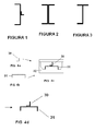
Figure 1 shows a C-shaped cross section of an L-shaped stiffener of a metallic frame known in the art. -
Figure 2 shows an I-shaped cross section of a metallic frame known in the art. -
Figure 3 shows a J-shaped cross section of a metallic frame known in the art. -
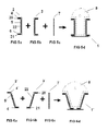
Figures 4a, 4b, 4c and 4d show a scheme of the steps of the manufacturing process for a frame with a stiffener made of a composite material according to the process known in the art. -
Figures 5a, 5b, 5c and 5d show a load frame made of composite material and the scheme of the steps of its manufacturing process according to a first embodiment of the invention. -
Figures 6a, 6b, 6c and 6d show a load frame made of composite material and the scheme of the steps of its manufacturing process according to a second embodiment of the invention. -
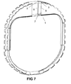
Figure 7 shows a general view of a load frame according to the invention. - According to a first embodiment of the invention, a
frame 1 with a Π-shaped section is proposed comprising three elements: twoside elements 2 and 3 and abase element 7 joining the inner flanges of the previously mentionedside elements 2, 3 of the frame. Each of theside elements 2, 3 further comprises the following parts: aleg 4 for joining theframe 1 and the skin of the aircraft fuselage; aweb 5 which is the thin part and which in some cases, depending on the function the frame is to carry out, forms a 90° angle with theleg 4, being able to form any other angle, and an inner flange 6 joining theweb 5 and thebase element 7. - The
leg 4, the inner flange 6, and theweb 5 of theframe 1 are formed by layers of composite material arranged at 0°, +/-45° and 90°. - The composite material can be fiber carbon or fiberglass with thermosetting or thermoplastic resin.
-
Unidirectional fiber reinforcements leg 4 and in the inner flange 6 at 0°, made of the same material or of a compatible material, longitudinally extending along theentire frame 1 continuously. The material of thereinforcements leg 4 and the inner flange 6 high strength and high stiffening capacity. - The web 6 of the
frame 1 can also havereinforcements 22 made of the same material or of a compatible material in any direction. Thereinforcements 22 of theweb 5 of theframe 1 can be continuous along the entire frame or they can be local, depending on the demands theframe 1 is subjected to. This means that theweb 5 is thus able to withstand much greater loads than if it were exclusively made of fabric at +/- 45°. - The
base element 7 of theframe 1 is formed by layers of unidirectional tape, stacked with different orientations, with a high percentage of such tapes in the longitudinal direction (0°). Thebase element 7 thus has a high modulus of elasticity in the longitudinal direction as a result of the high percentage of fibers in said direction, which extend continuously along theentire frame 1. - One of the possible processes for the manufacture of the
base element 7 is the automatic tape layer (ATL). Thisbase element 7 can be riveted, glued or sewn to theinner flanges 5 of theframe 1, thus closing the section of saidframe 1. The thicknesses and the sections of theside elements 2, 3 and of thebase element 7 are variable. - In addition to provided the advantages of a closed section as a result of having the inner flanges facing outwardly, the Π-shaped section of the
frame 1 proposed by the invention also facilitates the subsequent installation of systems and the attachment of the aircraft wiring. - The
frame 1 of the invention in many cases has local load inputs through fittings 8 joined to thewebs 5 of theframe 1. Theframe 1 together with the skin form a torsion box, therefore the assembly has a high torsional stiffness, the shear load transferred by these fittings 8 thus being advantageously distributed between two faces formed by thewebs 5. - According to a second embodiment of the invention, a frame 1' is proposed for aircraft with a Π-shaped section, the webs 5' of which form a certain angle with the legs 4' according to the function the frame 1' is to carry out. In this case, as can be seen in
Figures 6a to 6d , the bending direction of the inner flanges 6' is changed since the riveting of the inner flanges 6' to the base 7' could not otherwise be done. - In both embodiments, whether or not the webs are inclined it is necessary to be able to ensure that the fittings can be inspected. In the case of vertical webs, this accessibility can be achieved by making the riveting of the
base element 7 detachable. In the case of inclined webs, holes called hand-holes would have to be made in thebase element 7 which would allow inspecting the fittings 8 or enabling caps. On the other hand and as a result, the riveting of thebase element 7 to the inner flange 6 could be done without using blind rivets. - The frame with a Π-shaped section described by either of the two embodiments of the invention can extend along the
entire frame 1, 1' or encompass only a certain section thereof. This concept of a frame with a Π-shaped section can further be applied to different fuselage sections, such as a circular, ellipsoidal or rectangular section or the like. - This concept of a frame with a Π-shaped section according to the invention is furthermore compatible with other frame sections. Thus, for example, in areas far from the load input the same frame with a Π-shaped section can go from a frame with sections having a side element with a web and leg forming a 90° angle and the other side element with a web and leg forming an angle that is greater than 90°, to traditional C, J and I-shaped sections, and even Ω-shaped sections, with a suitable transition and joining as can be seen in
Figure 7 . - The manufacturing process of the elements forming the
frames 1, 1' made of a composite material described above is done separately. - As can be seen in
Figures 4a to 4d , the traditional carbon fiber frames, such as a C-shaped frame 31 for example with an L-shaped stiffener made of a composite material are usually manufactured by means of the resin transfer molding (RTM) process, using a closed and pressurizedmold 32 for that purpose wheredry preforms - The
side elements 2, 3 forming theframes 1, 1' out of a composite material of the present invention are manufactured separately, preferably by means of conventional resin transfer molding (RTM). Thebase part 7 closing the section of the frame is preferably manufactured by means of an ATL process. These elements will be later joined together to form the frame, obtaining a closed section that can include section and thickness changes based on simpler elements. Therefore, since these three elements are manufactured separately, each one with thickness and section variations, the load frame obtained when they are joined together is optimized, obtaining a variable closed section in a simple manner. The manufacturing process of theside elements 2, 3 forming theframes 1, 1' of a composite material preferably comprises the following steps: - a) cutting fabrics and manufacturing patterns by means of a blade or water jet;
- b) manufacturing the preforms by means of the manual stacking of the patterns, sewing and cold or hot compaction;
- c) placing the preforms in the mold;
- d) applying a vacuum;
- e) injecting resin by applying pressure;
- f) curing the resin by means of applying heat;
- g) demolding.
- The
base element 7 is preferably manufactured by means of ATL, this process consisting of the following steps: - a) automatic stacking of fabrics;
- b) hot forming;
- c) vacuum bag placement
- d) autoclave curing.
- Any modifications comprised within the scope defined by the attached claims can be introduced in the embodiments described above.
Claims (11)
- An aircraft load frame (1) made of a composite material, characterized in that it comprises two side elements (2, 3) and a base element (7), the side elements (2, 3) being joined at the inner part of the frame (1) by means of the base element (7) and each of the side elements (2, 3) comprising a leg (4) joining the frame (1) to the aircraft fuselage skin, a web (5) and a lower flange (6) joining the web (5) and the base element (7).
- An aircraft load frame (1) made of a composite material according to claim 1, characterized in that the web (5) of the side elements (2, 3) is perpendicular to the leg (4) and the inner flange (6).
- An aircraft load frame (1) made of a composite material according to claim 1, characterized in that the web (5) of the side elements (2, 3) forms an angle that is greater than 90° in relation to the leg (4), forming the corresponding supplementary angle in relation to the inner flange (6).
- An aircraft load frame (1) made of a composite material according to any of the previous claims, characterized in that the leg (4) the web (5) and the inner flange (6) are formed by layers of composite material.
- An aircraft load frame (1) made of a composite material according to claim 4, characterized in that the layers of composite material are arranged at +/- 45°.
- An aircraft load frame (1) made of a composite material according to claim 5, characterized in that it also comprises layers of composite material arranged at 0°/90°.
- An aircraft load frame (1) made of a composite material according to any of the previous claims, characterized in that the leg (4) and the inner flange (6) have unidirectional fiber reinforcements (20, 21) at 0° extending continuously along the frame (1).
- An aircraft load frame (1) made of a composite material according to any of the previous claims, characterized in that the web (5) has continuous or local reinforcements (22) in any direction.
- An aircraft load frame (1) made of a composite material according to any of the previous claims, characterized in that the base element (7) is formed by layers of unidirectional tape with different orientations.
- An aircraft load frame (1) made of a composite material according to any of the previous claims, characterized in that it comprises fittings (8) for local load inputs.
- An aircraft load frame (1) made of a composite material according to any of the previous claims, characterized in that the section of the frame (1) and the thickness of the section of said frame (1) are variable.
Applications Claiming Priority (1)
| Application Number | Priority Date | Filing Date | Title |
|---|---|---|---|
| PCT/ES2007/070020 WO2008092970A1 (en) | 2007-01-29 | 2007-01-29 | Aircraft loading frame of composite material |
Publications (2)
| Publication Number | Publication Date |
|---|---|
| EP2128018A1 true EP2128018A1 (en) | 2009-12-02 |
| EP2128018A4 EP2128018A4 (en) | 2013-09-18 |
Family
ID=39666852
Family Applications (1)
| Application Number | Title | Priority Date | Filing Date |
|---|---|---|---|
| EP07704780.1A Withdrawn EP2128018A4 (en) | 2007-01-29 | 2007-01-29 | Aircraft loading frame of composite material |
Country Status (4)
| Country | Link |
|---|---|
| US (1) | US8418963B2 (en) |
| EP (1) | EP2128018A4 (en) |
| CN (1) | CN101715411A (en) |
| WO (1) | WO2008092970A1 (en) |
Families Citing this family (17)
| Publication number | Priority date | Publication date | Assignee | Title |
|---|---|---|---|---|
| DE102006026170B4 (en) * | 2006-06-06 | 2012-06-21 | Airbus Operations Gmbh | Aircraft fuselage structure and method for its manufacture |
| DE102006026168A1 (en) | 2006-06-06 | 2008-01-31 | Airbus Deutschland Gmbh | Aircraft fuselage structure and method for its manufacture |
| DE102006026169B4 (en) * | 2006-06-06 | 2012-06-21 | Airbus Operations Gmbh | Aircraft fuselage structure and method for its manufacture |
| US8336820B2 (en) * | 2008-10-27 | 2012-12-25 | Embraer S.A. | Aircraft cabin floor structures, systems and methods |
| ES2385993B1 (en) | 2008-12-18 | 2013-06-17 | Airbus Operations, S.L. | Rear fuselage of an aircraft with a load introduction zone of a horizontal tail stabilizer and a vertical tail stabilizer comprising load receiving elements of said stabilizers attached to structural elements of the fuselage. |
| FR2947241B1 (en) * | 2009-06-29 | 2012-12-07 | Airbus France | FRAMING OF AN OPENING UNDERTAKEN IN AN AIRCRAFT FUSELAGE |
| ES2384349B1 (en) | 2009-12-30 | 2013-05-16 | Airbus Operations, S.L. | AIRCRAFT FUSELAGE NOTEBOOK IN COMPOSITE MATERIAL WITH STABILIZING RIBS. |
| ES2383986B1 (en) | 2009-12-30 | 2013-05-16 | Airbus Operations, S.L. | AIRCRAFT FUSELAGE NOTEBOOK IN COMPOSITE MATERIAL WITH STABILIZED SOUL. |
| ES2401517B1 (en) * | 2011-05-31 | 2014-06-18 | Airbus Operations S.L. | AIRCRAFT NOTEBOOK IN COMPOSITE MATERIAL. |
| US8651419B2 (en) * | 2011-07-18 | 2014-02-18 | The Boeing Company | Flexible truss frame and method of making the same |
| ES2645628T3 (en) | 2011-12-01 | 2017-12-07 | Airbus Operations S.L. | Highly loaded frame of an aircraft fuselage with a lattice-shaped soul |
| DE102012016553A1 (en) * | 2012-08-22 | 2014-02-27 | Airbus Operations Gmbh | Pressure hull of an aircraft comprising a pressure bulkhead |
| US9145197B2 (en) * | 2012-11-26 | 2015-09-29 | The Boeing Company | Vertically integrated stringers |
| FR3009273B1 (en) | 2013-07-30 | 2017-07-28 | Eurocopter France | LAMINATE COMPOSITE MATERIAL FRAME FOR AIRCRAFT FUSELAGE HAVING AN EVOLVING CURVED BEND RADIATION ZONES |
| US10093406B2 (en) * | 2014-12-10 | 2018-10-09 | The Boeing Company | Aircraft frame for tailstrike angle enhancement |
| US20180327071A1 (en) * | 2017-05-10 | 2018-11-15 | The Boeing Company | Systems and methods for aircraft integrated composite frames |
| RU2694486C1 (en) * | 2018-10-05 | 2019-07-15 | Акционерное общество "Научно-производственное объединение им. С.А. Лавочкина" | Former |
Citations (5)
| Publication number | Priority date | Publication date | Assignee | Title |
|---|---|---|---|---|
| US4198018A (en) * | 1978-03-13 | 1980-04-15 | The Boeing Company | Blended wing-fuselage frame made of fiber reinforced resin composites |
| GB2196922A (en) * | 1986-09-26 | 1988-05-11 | Airship Ind | Airship gondola construction |
| US4786343A (en) * | 1985-05-10 | 1988-11-22 | The Boeing Company | Method of making delamination resistant composites |
| US5171510A (en) * | 1988-06-08 | 1992-12-15 | Aerospatiale Societe Nationale Industrielle | Method of producing a frame made of a composite material, especially for the fuselage of an aircraft |
| US6427945B1 (en) * | 1999-05-14 | 2002-08-06 | Eurocopter Deutschland Gmbh | Subfloor structure of an aircraft airframe |
Family Cites Families (8)
| Publication number | Priority date | Publication date | Assignee | Title |
|---|---|---|---|---|
| WO1980002254A1 (en) * | 1979-04-16 | 1980-10-30 | H Forsch | Stitch bond fastening of composite structures |
| DE3401189A1 (en) * | 1983-01-25 | 1984-07-26 | Westland PLC, Yeovil, Somerset | COMPOSITE HELICOPTER FUSELAGE |
| FR2632604B1 (en) * | 1988-06-08 | 1991-07-12 | Aerospatiale | FRAME OF COMPOSITE MATERIAL IN PARTICULAR FOR AIRCRAFT FUSELAGE, AND METHOD FOR MANUFACTURING SAME |
| US6217000B1 (en) * | 1996-10-25 | 2001-04-17 | The Boeing Company | Composite fabrication method and tooling to improve part consolidation |
| US6889937B2 (en) * | 1999-11-18 | 2005-05-10 | Rocky Mountain Composites, Inc. | Single piece co-cure composite wing |
| EP1547756A1 (en) * | 2003-12-24 | 2005-06-29 | Airbus UK Limited | Method of manufacturing aircraft components |
| US7871040B2 (en) * | 2006-11-10 | 2011-01-18 | The Boeing Company | Composite aircraft structures with hat stiffeners |
| US7721995B2 (en) * | 2006-12-13 | 2010-05-25 | The Boeing Company | Rib support for wing panels |
-
2007
- 2007-01-29 EP EP07704780.1A patent/EP2128018A4/en not_active Withdrawn
- 2007-01-29 WO PCT/ES2007/070020 patent/WO2008092970A1/en active Application Filing
- 2007-01-29 CN CN200780052327A patent/CN101715411A/en active Pending
- 2007-03-29 US US11/729,990 patent/US8418963B2/en not_active Expired - Fee Related
Patent Citations (5)
| Publication number | Priority date | Publication date | Assignee | Title |
|---|---|---|---|---|
| US4198018A (en) * | 1978-03-13 | 1980-04-15 | The Boeing Company | Blended wing-fuselage frame made of fiber reinforced resin composites |
| US4786343A (en) * | 1985-05-10 | 1988-11-22 | The Boeing Company | Method of making delamination resistant composites |
| GB2196922A (en) * | 1986-09-26 | 1988-05-11 | Airship Ind | Airship gondola construction |
| US5171510A (en) * | 1988-06-08 | 1992-12-15 | Aerospatiale Societe Nationale Industrielle | Method of producing a frame made of a composite material, especially for the fuselage of an aircraft |
| US6427945B1 (en) * | 1999-05-14 | 2002-08-06 | Eurocopter Deutschland Gmbh | Subfloor structure of an aircraft airframe |
Non-Patent Citations (1)
| Title |
|---|
| See also references of WO2008092970A1 * |
Also Published As
| Publication number | Publication date |
|---|---|
| CN101715411A (en) | 2010-05-26 |
| US8418963B2 (en) | 2013-04-16 |
| WO2008092970A1 (en) | 2008-08-07 |
| EP2128018A4 (en) | 2013-09-18 |
| US20080179460A1 (en) | 2008-07-31 |
Similar Documents
| Publication | Publication Date | Title |
|---|---|---|
| US8418963B2 (en) | Aircraft load frame made of a composite material | |
| US8096504B2 (en) | Integrated aircraft structure in composite material | |
| EP2153979B1 (en) | Multispar torsion box made from composite material | |
| US9771140B2 (en) | Aircraft structure with integrated reinforcing elements | |
| US9669919B2 (en) | Highly integrated infused box made of composite material and method of manufacturing | |
| US7182293B2 (en) | Airfoil box and associated method | |
| US9637216B2 (en) | Aircraft structure made of composite material | |
| US20100032524A1 (en) | Apparatuses and methods for joining composite members and other structural members in aircraft wing boxes and other structures | |
| US20120001023A1 (en) | Aircraft fuselage made out with composite material and manufacturing processes | |
| US9862477B2 (en) | Aircraft structure | |
| US20170088249A1 (en) | Composite rib for a torsion box and manufacturing method thereof | |
| US9840041B2 (en) | Stiffening element and reinforced structure | |
| US9034453B2 (en) | Reinforced aircraft fuselage panel and method of manufacture | |
| US10843786B2 (en) | Reinforcing arrangement for an opening in an aircraft structure | |
| US20140295113A1 (en) | Composite reinforcement component, structural element, aircraft or spacecraft and method for producing a composite reinforcement component | |
| US20140120302A1 (en) | Stringer made of composite material with an elastic run-out and method of manufacturing same | |
| US9701393B2 (en) | Highly integrated inner structure of a torsion box of an aircraft lifting surface | |
| EP3597525B1 (en) | Curved composite part and manufacturing method thereof | |
| US9868508B2 (en) | Rib foot for aircraft wing | |
| RU2448865C2 (en) | Aircraft mainframe made from composite material |
Legal Events
| Date | Code | Title | Description |
|---|---|---|---|
| PUAI | Public reference made under article 153(3) epc to a published international application that has entered the european phase |
Free format text: ORIGINAL CODE: 0009012 |
|
| 17P | Request for examination filed |
Effective date: 20090825 |
|
| AK | Designated contracting states |
Kind code of ref document: A1 Designated state(s): AT BE BG CH CY CZ DE DK EE ES FI FR GB GR HU IE IS IT LI LT LU LV MC NL PL PT RO SE SI SK TR |
|
| RIN1 | Information on inventor provided before grant (corrected) |
Inventor name: ORTEGA JUARISTI, CRISTINA Inventor name: BAUTISTA DE LA LLAVE, CESAR Inventor name: AREVALO RODRIGUEZ, ELENA |
|
| DAX | Request for extension of the european patent (deleted) | ||
| A4 | Supplementary search report drawn up and despatched |
Effective date: 20130820 |
|
| RIC1 | Information provided on ipc code assigned before grant |
Ipc: B64C 1/06 20060101AFI20130813BHEP Ipc: B29C 70/34 20060101ALI20130813BHEP Ipc: B64C 1/10 20060101ALI20130813BHEP |
|
| STAA | Information on the status of an ep patent application or granted ep patent |
Free format text: STATUS: EXAMINATION IS IN PROGRESS |
|
| 17Q | First examination report despatched |
Effective date: 20171220 |
|
| STAA | Information on the status of an ep patent application or granted ep patent |
Free format text: STATUS: THE APPLICATION IS DEEMED TO BE WITHDRAWN |
|
| 18D | Application deemed to be withdrawn |
Effective date: 20190521 |