EP2127978A1 - Negative pressure booster and brake booster using the same - Google Patents
Negative pressure booster and brake booster using the same Download PDFInfo
- Publication number
- EP2127978A1 EP2127978A1 EP08703748A EP08703748A EP2127978A1 EP 2127978 A1 EP2127978 A1 EP 2127978A1 EP 08703748 A EP08703748 A EP 08703748A EP 08703748 A EP08703748 A EP 08703748A EP 2127978 A1 EP2127978 A1 EP 2127978A1
- Authority
- EP
- European Patent Office
- Prior art keywords
- valve
- atmosphere
- side fixed
- negative pressure
- fixed portion
- Prior art date
- Legal status (The legal status is an assumption and is not a legal conclusion. Google has not performed a legal analysis and makes no representation as to the accuracy of the status listed.)
- Granted
Links
Images
Classifications
-
- B—PERFORMING OPERATIONS; TRANSPORTING
- B60—VEHICLES IN GENERAL
- B60T—VEHICLE BRAKE CONTROL SYSTEMS OR PARTS THEREOF; BRAKE CONTROL SYSTEMS OR PARTS THEREOF, IN GENERAL; ARRANGEMENT OF BRAKING ELEMENTS ON VEHICLES IN GENERAL; PORTABLE DEVICES FOR PREVENTING UNWANTED MOVEMENT OF VEHICLES; VEHICLE MODIFICATIONS TO FACILITATE COOLING OF BRAKES
- B60T13/00—Transmitting braking action from initiating means to ultimate brake actuator with power assistance or drive; Brake systems incorporating such transmitting means, e.g. air-pressure brake systems
- B60T13/10—Transmitting braking action from initiating means to ultimate brake actuator with power assistance or drive; Brake systems incorporating such transmitting means, e.g. air-pressure brake systems with fluid assistance, drive, or release
- B60T13/24—Transmitting braking action from initiating means to ultimate brake actuator with power assistance or drive; Brake systems incorporating such transmitting means, e.g. air-pressure brake systems with fluid assistance, drive, or release the fluid being gaseous
- B60T13/46—Vacuum systems
- B60T13/52—Vacuum systems indirect, i.e. vacuum booster units
- B60T13/57—Vacuum systems indirect, i.e. vacuum booster units characterised by constructional features of control valves
Definitions
- the present invention relates to a technical field of a negative pressure booster configured to boost an input by a negative pressure at a predetermined servo ratio to generate a large output and a brake booster using the same and, more specifically, to a technical field of a negative pressure booster configured to be able to restrain a noise generated by atmosphere flowing in during operation and a brake booster.
- the relation in direction between the front and the rear is determined such that "front” is a direction in which an input shaft moves when the negative pressure booster is in operation, and "rear” is a direction in which the input shaft returns when the operation is canceled.
- a fact that a negative pressure booster using a negative pressure is used in a brake booster in a brake system for a vehicle such as a passenger car is known by a patent publication JP-A-5-193485 .
- a general negative pressure booster in the related art is sectionalized into a constant pressure chamber in which the negative pressure is introduced by a power piston under the normal condition and a variable pressure chamber in which a pressure varies. Then, at the time of normal braking operation by a normal depression of a brake pedal, a control valve is switched by an advance of an input shaft, and atmosphere is introduced in the variable pressure chamber.
- the negative pressure booster boosts an input from the input shaft (that is, a pedal depressing force) by a predetermined servo ratio and outputs the same.
- the output from the negative pressure booster causes a master cylinder to generate a master cylinder pressure, and the master cylinder pressure activates a wheel cylinder, whereby the brake is normally activated.
- a noise absorbing member is provided in the atmosphere inlet passage in the vicinity of an atmospheric air suction port in the valve body which stores and supports the control valve, and resistance is provided to the flow of the atmosphere by the noise absorbing member, so that the flow-in velocity of the atmosphere flowing into the variable pressure chamber is reduced to prevent generation of the inflow noise.
- a boot having an accordion portion is provided between a rear shell and the input shaft so as to be expandable and contractible in order to prevent contamination such as foreign substances included in the atmosphere from entering the valve body together with the atmosphere when the atmosphere flows into the valve body.
- the boot is formed with atmosphere inlet ports for allowing introduction of the atmosphere therethrough during operation.
- a filter formed of soft material such as sponge is provided adjacently to the noise absorbing member (silencer) so as to be supported by the boot.
- the accordion portion of the boot is expanded and contracted across a large range by the input shaft advancing significantly forward respect to the rear shell during operation.
- An elastically restoring force of the accordion portion of the boot is set to a relatively large value in order to ensure returning of the boot when the operation of the negative pressure booster is cancelled. Therefore, when the accordion portion of the boot is expanded and contracted during operation, the elastically restoring force of the accordion portion is increased. Therefore, a rear end portion of the boot supported by the input shaft is pressed by the elastically restoring force and hence is deformed, so that the atmosphere inlet ports formed at the rear end portion of the boot are collapsed. Therefore, there is a risk of generation of noise due to the turbulence of the atmosphere flow when the atmosphere flows through the atmosphere inlet ports.
- the soft filter supported by the boot and is supported by the input shaft via the rear end portion of the boot is also deformed by being pressed by the elastically restoring force of the accordion portion, so that there arises problems of not only impairment of a contamination removing function of the filter, but also lowering of the responsiveness.
- a negative pressure booster at least includes: an input shaft which is applied with input; a valve body disposed so as to be capable of moving forward and backward with respect to the rear shell; a power piston provided in the valve body for sectionalizing a space between a front shell and the rear shell into a constant pressure chamber in which a negative pressure is introduced, and a variable pressure chamber in which the atmosphere is introduced during operation; an output shaft connected to the valve body for outputting an output generated by the power piston and being boosted from the input via the valve body; a valve plunger connected to the input shaft and disposed in the valve body so as to be capable of sliding therein; a vacuum valve for controlling communication or blocking between the constant pressure chamber and the variable pressure chamber by the operation of the valve plunger; an atmosphere valve for controlling blocking or communication between the variable pressure chamber and at least the atmosphere; and an expandable and contractible boot provided between the rear shell and the input shaft, and is characterized in that the boot includes an accordion portion provided on the side of being connected to
- the negative pressure booster according to the present invention is characterized in that the boot is formed with the atmosphere inlet ports in the radial direction on a side surface between the valve-body-side fixed portion and the input-shaft-side fixed portion.
- the negative pressure booster according to the invention of the present invention is characterized in that a filter storage portion is provided in the boot between the valve-body-side fixed portion and the input-shaft-side fixed portion, and the filter is stored in the filter storage portion.
- a brake booster according to the invention of the present invention is used in a brake system in a vehicle and includes a negative pressure booster configured to boost a pedal depressing force applied on a brake pedal and output the same, and is characterized in that the negative pressure booster is the negative pressure booster according to the preset invention.
- the valve-body-side fixed portion is provided on the rear end portion on the rear side of the accordion portion of the boot provided between the rear shell and the input shaft, the valve-body-side fixed portion is fixed to or axially engaged with the valve body, the input-shaft-side fixed portion provided at the rear end of the boot on the rear side of the valve-body-side fixed portion is fixed to the input shaft, and the boot portion is formed with a predetermined number of the atmosphere inlet ports between the valve-body-side fixed portion and the input-shaft-side fixed portion. Therefore, when the negative pressure booster is in operation, an elastically restoring force of the contracted accordion portion of the boot is supported by the valve body.
- the boot portion between the valve-body-side fixed portion and the input-shaft-side fixed portion is not deformed, and hence the atmosphere inlet ports are prevented from being collapsed and deformed. Accordingly, turbulence of the flow of the atmosphere on the basis of the collapse and deformation of the atmosphere inlet ports is restrained when the atmosphere flows through the atmosphere inlet ports, so that the atmosphere is allowed to flow relatively smoothly through the atmosphere inlet ports. Therefore, restraint of the inflow noise generating when the atmosphere flows through the atmosphere inlet ports is achieved.
- the predetermined number of atmosphere inlet ports are formed in the radial direction on a cylindrical side surface portion of the boot between the valve-body-side fixed portion and the input-shaft-side fixed portion, deformation of the cylindrical side surface portion of the boot between the valve-body-side fixed portion and the input-shaft-side fixed portion due to the elastically restoring force of the accordion portion of the contracted boot hardly occurs when the negative pressure booster is in operation, so that the collapse and deformation of the atmosphere inlet ports may be restrained further effectively. Accordingly, the atmosphere is flowed through the atmosphere inlet ports more smoothly, and the inflow noise generated when the atmosphere flows through the atmosphere inlet ports is restrained further effectively.
- the filter Since the filter is stored in the boot between the valve-body-side fixed portion and the input-shaft-side fixed portion, the elastically restoring force of the accordion portion of the contracted boot is prevented from affecting on the filter when the negative pressure booster is in operation. Accordingly, deformation of the filter is restrained, and hence the contamination removing function of the filter is satisfactorily maintained.
- the resistance of the filter may be reduced, the atmosphere is allowed to flow smoothly in the filter. Then, since the atmosphere is allowed to flow smoothly through the atmosphere inlet ports and the filter in this manner, the responsiveness of the negative pressure booster is improved. In addition, since a noise reduction member (silencer) as in the related art is not necessary, the cost of the negative pressure booster may be reduced.
- the brake booster in the present invention since the negative pressure booster which achieves prevention of generation of the inflow noise of the atmosphere more effectively is employed, the quietness in the cabin of the motor vehicle is achieved, so that the comfortableness of occupants in the cabin is improved.
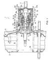
- Fig. 1 is a partial cross-sectional view showing an example of embodiments of a negative pressure booster according to the present invention in a non-operating state
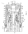
- Fig. 2 is a partially enlarged cross-sectional view of Fig. 1 .
- the negative pressure booster in the present invention is applied to a brake booster.
- reference numeral 1 designates a negative pressure booster
- reference numeral 2 designates a front shell
- reference numeral 3 designates a rear shell
- reference numeral 4 designates a valve body
- reference numeral 5 designates a power piston including a power piston member 6 mounted on the valve body 4 and a diaphragm 7 provided between the valve body 4 and the both shells 2,
- reference numeral 8 designates a constant pressure chamber which is one of two chambers defined by sectionalizing a space in the both shells 2, 3 by the power piston 5 and being introduced with a negative pressure in a normal condition
- reference numeral 9 designates a variable pressure chamber which is the other one of the two chambers described above, and being introduced with atmospheric pressure when the negative pressure booster 1 is in operation
- reference numeral 10 designates a valve plunger
- reference numeral 11 designates
- the negative pressure booster 1 in this example is not provided with a noise reduction member (silencer) as in the related art in an atmosphere introducing portion of the valve body 4.
- the valve element 12 is formed cylindrically and is provided on the valve body 4 (more specifically, a valve body auxiliary member 30 described later) slidably in an airtight manner, and includes the atmosphere valve portion 12a, the vacuum valve portion 12b, and a substantially cylindrical connecting member 12c which connects the same so as to be capable of moving integrally.
- the negative pressure booster 1 in this example is fitted to an axial inner hole 4b of the valve body 4 so as to allow sliding motion of a cylindrical vacuum valve seat member 29. Then, the vacuum valve seat 13 described above is provided on the inner peripheral side at the rear end of the vacuum valve seat member 29. Therefore, the vacuum valve seat 13 is also movable relatively with respect to the valve body 4.
- a pressure in the variable pressure chamber 9 is applied constantly to a front end surface 29a of the vacuum valve seat member 29, and a pressure (negative pressure) of the constant pressure chamber 8 is constantly applied to a rear end surface 29b of the vacuum valve seat member 29. Therefore, when the pressure difference is generated between the pressure in the variable pressure chamber 9 and the pressure in the constant pressure chamber 8 when the negative pressure booster 1 is in operation, the force caused by this pressure difference is applied to the vacuum valve seat member 29 toward the rear.
- the stepped cylindrical valve body auxiliary member 30 is fixedly fitted to the inner peripheral surface of the rear end portion of the valve body 4 so as not to be movable in the direction.
- a second valve control spring 31 is provided between the stepped portion of the outer peripheral surface of the valve body auxiliary member 30 and the rear end surface 29b of the vacuum valve seat member 29 in a compressed state.
- the second valve control spring 31 urges the vacuum valve seat member 29 constantly toward the front, and when the negative pressure booster 1 shown in Fig. 1 is in the non-operating state, the front end surface 29a of the vacuum valve seat member 29 comes into abutment with the stepped portion on the inner periphery of the valve body 4 and hence the vacuum valve seat member 29 is stopped with respect to the valve body 4.
- the atmosphere valve portion 12a of the valve element 12 is provided on a cylindrical atmosphere valve member 12d formed of an elastic material such as rubber, and an annular lip portion 12e is formed on the outer peripheral surface of the rear end portion of the atmosphere valve member 12d.
- the lip portion 12e is fitted in an inner peripheral surface 30a of the cylindrical portion at the front end of the valve body auxiliary member 30 slidably in an airtight manner. Therefore, a chamber 32 formed on the outer periphery of the atmosphere valve member 12d and the front end of the valve body auxiliary member 30 is constantly isolated from the atmosphere inlet passage 19 inside the valve body auxiliary member 30 in an airtight manner.
- the first valve control spring 18 is provided between an inner peripheral stepped portion 12f of the atmosphere valve member 12d and an outer peripheral stepped portion 11a of the input shaft 11 in a compressed state. Therefore, the first valve control spring 18 constantly urges the atmosphere valve member 12d forward, in other words, in a direction in which the vacuum valve portion 12b is seated on the vacuum valve seat 13.
- the first return spring 21 is provided between an inner peripheral stepped portion 30b of the valve body auxiliary member 30 and a flange portion 11b of the input shaft 11 in a compressed state. Therefore, the first return spring 21 is constantly urges the input shaft 11 rearward.
- the boot 20 disposed between the input shaft 11 and the rear shell 3 includes an accordion portion 20b formed between the rear end portion thereof and a mounting portion to the rear shell 3.
- the rear end portion of the boot 20 is formed into a cylindrical shape in U-shape in cross section having a bottom portion 20c formed of an annular flat panel fixed to the input shaft 11.
- An inner peripheral edge portion of a hole on the bottom portion 20c corresponds to an input-shaft-side fixed portion 20d which is fixed to the input shaft 11 in an airtight manner.
- the cylindrical portion in U-shape in cross section at the rear end portion of the boot 20 corresponds to a filter storing portion 20e.
- a filter 22 formed of a soft filter material such as sponge for removing contamination such as dust contained in introduced atmosphere is stored in the filter storing portion 20e.
- annular flange is formed at the front end of the filter storing portion 20e, and the annular flange corresponds to a valve-body-side fixed portion 20f to be fixed to the valve body auxiliary member 30 fixed to the valve body 4. Then, the valve-body-side fixed portion 20f of the boot 20 is fixedly fitted to an annular recess of the valve body auxiliary member 30.
- a predetermined number of atmosphere inlet ports 20a are formed on a cylindrical side surface portion of the filter storing portion 20e in the radial direction at adequate pitches in the circumferential direction.
- An annular filter 35 is provided on the inner peripheral surface of the cylindrical connecting member 12c of the valve element 12 and forwardly of the atmosphere valve 16.
- the filter 35 serves to remove the contamination such as dust contained in the atmosphere flowing through the opened atmosphere valve 16.
- Other configurations of the negative pressure booster 1 in this example are substantially the same as that in JP-A-5-193485 described above.
- the valve plunger 10 moves forward in the same manner as the negative pressure booster 1 disclosed in JP-A-5-193485 . Then, the valve element 12 also moves forward, and the vacuum valve portion 12b is seated on the vacuum valve seat 13 to close the vacuum valve 15, and the forward movement of the valve element 12 is stopped. Since the valve plunger 10 moves further forward, the atmosphere valve seat 14 moves away from the atmosphere valve portion 12a, so that the atmosphere valve 16 is opened.
- the atmosphere which is already flowed in to the atmosphere inlet passage 19 in the valve body 4 flows through the atmosphere valve 16 and flows into the variable pressure chamber 9, and atmosphere out of the valve body 4 flows into the atmosphere inlet passage 19 in the valve body 4 through the atmosphere inlet ports 20a and the filter 22.
- the atmosphere flowed into the atmosphere inlet passage 19 also flows through the opened atmosphere valve 16 and flows into the variable pressure chamber 9.
- the valve-body-side fixed portion 20f at the rear end portion of the boot is fixed to the valve body 4 (more specifically, to the valve body auxiliary member 30), the elastically restoring force of the accordion portion 20b is supported by the valve body 4 via the valve-body-side fixed portion 20f. Accordingly, the elastically restoring force of the accordion portion 20b does not affect the rear end portion of the boot at a position rearwardly of the valve-body-side fixed portion 20f. Therefore, the atmosphere inlet ports 20a at the rear end portion of the boot is not collapsed and deformed, so that the turbulent of the flow of the atmosphere rarely occurs when the atmosphere passes through the atmosphere inlet ports 20a. Consequently, generation of the inflow noise of the atmosphere is restrained when the atmosphere passes through the atmosphere inlet ports 20a.
- the filter 22 is not affected by the elastically restoring force of the accordion portion 20b. Therefore, the deformation of the filter 22 is restrained and the atmosphere is able to flow with little resistance when passing through the filter 22. Accordingly, the responsiveness of the negative pressure booster 1 is satisfactorily maintained. In addition, since the deformation of the filter 22 is restrained, a contamination removing function of the filter 22 is satisfactorily maintained as well.
- the atmosphere valve portion 12a When the valve body 4 moves forward by a predetermined amount, the atmosphere valve portion 12a is seated on the atmosphere valve seat 14, and the atmosphere valve 16 is closed.
- an output of the negative pressure booster 1 In an intermediate load condition in which the negative pressure booster 1 boosts an input to output, when the vacuum valve 15 and the atmosphere valve 16 are both closed, an output of the negative pressure booster 1 has a margin obtained by boosting the input by a predetermined servo ratio, so that the input and the output are well balanced.
- the vacuum valve seat member 29 will be described briefly although it is not a characteristic part of the present invention.
- the atmosphere flows into the variable pressure chamber 9, it acts on the front end surface 29a of the vacuum valve seat member 29 of the variable pressure chamber 9 toward the rear. Therefore, by the pressure difference between the pressure in the variable pressure chamber 9 applied on the front end surface 29a of the vacuum valve seat member 29 and the pressure in the constant pressure chamber 8 applied on the rear end surface 29b of the vacuum valve seat member 29, a force to press the vacuum valve seat member 29 rearward is applied to the vacuum valve seat member 29. This force increases with increase in pressure in the variable pressure chamber 9.
- the valve-body-side fixed portion 20f provided at the rear end portion at a position rearwardly of the accordion portion 20b of the boot 20, which is provided between the rear shell 3 and the input shaft 11, is fixed to the valve body 4
- the input-shaft-side fixed portion 20d provided at the rear end of the boot 20 at a position rearwardly of the valve-body-side fixed portion 20f is fixed to the input shaft 11, and the predetermined number of atmosphere inlet ports 20a are formed in the radial direction on the cylindrical side surface portion of the boot 20 at a position between the valve-body-side fixed portion 20f and the input-shaft-side fixed portion 20d
- the elastically restoring force of the accordion portion 20b of the contracted boot 20 is supported by the valve body 4 when the negative pressure booster 1 is in operation.
- the cylindrical side surface portion of the boot 20 between the valve-body-side fixed portion 20f and the input-shaft-side fixed portion 20d is not deformed, and hence the atmosphere inlet ports 20a are prevented from being collapsed and deformed. Accordingly, turbulence of the flow of atmosphere is restrained when the atmosphere flows through the atmosphere inlet ports 20a, so that the atmosphere is allowed to flow relatively smoothly through the atmosphere inlet ports 20a. Therefore, restraint of the inflow noise generating when the atmosphere flows through the atmosphere inlet ports 20a is achieved.
- the filter 22 Since the filter 22 is stored in the filter storing portion 20e provided in the boot 20 between the valve-body-side fixed portion 20f and the input-shaft-side fixed portion 20d, the elastically restoring force of the accordion portion 20b of the contracted boot 20 is prevented from affecting on the filter 22 when the negative pressure booster 1 is in operation. Accordingly, since the deformation of the filter 22 is prevented, and the filter 22 is stored in the boot 20 between the valve-body-side fixed portion 20f and the input-shaft-side fixed portion 20d, the elastically restoring force of the accordion portion 20b of the contracted boot 22 is prevented from affecting on the filter 22 when the negative pressure booster 1 is in operation. Accordingly, deformation of the filter 22 is restrained, and hence the contamination removing function of the filter 22 is satisfactorily maintained.
- the resistance of the filter 22 may be reduced with respect to the flow of the atmosphere, and the atmosphere is allowed to flow smoothly in the filter 22. Then, since the atmosphere is allowed to flow smoothly through the atmosphere inlet ports 20a and the filter 22, the responsiveness of the negative pressure booster 1 is improved. In addition, since the noise reduction member (silencer) as in the related art is not necessary, the cost of the negative pressure booster 1 may be reduced.
- valve-body-side fixed portion 20f of the boot 20 is fixedly fitted into the annular recess formed on the valve body auxiliary member 30 in the example described above, the present invention may be configured in such a manner that an annular projection is formed on the outer peripheral surface of the valve body auxiliary member 30, and the front surface of the annular projection is engaged with the rear surface of the valve-body-side fixed portion 20f at the end thereof.
- the predetermined number of atmosphere inlet ports 20a are formed on the cylindrical side surface portion of the filter storing portion 20e of the boot 20 in the radial direction in the example shown above, the predetermined number of atmosphere inlet ports 20a may be formed on the bottom portion 20c of the rear end portion of the boot 20 in the axial direction.
- the cylindrical vacuum valve seat member 29 is provided in the valve body 4, the vacuum valve seat member 29 is not necessarily required in the negative pressure booster 1 in the present invention, and may be omitted as the negative pressure booster disclosed in JP-A-5-193485 .
- the vacuum valve 15 and the atmosphere valve 16 are provided in series in the axial direction in the example described above, the vacuum valve 15 and the atmosphere valve 16 do not necessarily have to be provided in series in the axial direction in the negative pressure booster 1 in the present invention.
- the vacuum valve 15 and the atmosphere valve 16 may be provided in an identical plane which is orthogonal to the axial direction of the valve body 4 as in the known negative pressure booster in the related art.
- valve body auxiliary member 30 is provided in the valve body 4 in the example described above, the valve body auxiliary member 30 may be omitted in the present invention.
- the brake booster in the present invention since the negative pressure booster 1 which achieves prevention of generation of the inflow noise of the atmosphere more effectively is employed, the quietness in the cabin of the motor vehicle is achieved, so that the comfortableness of occupants in the cabin is improved.
- a negative pressure booster according to the present invention is applicable to a negative pressure booster which generates a large output by boosting an input by a negative pressure at a predetermined servo ratio and, specifically, preferably applicable to a negative pressure booster in which quietness is required during operation.
- a brake booster according to the present invention generates a large braking force by boosting a pedal depressing force by the negative pressure and is preferably applicable to a brake booster for a vehicle in which quietness in the cabin is required.
Landscapes
- Engineering & Computer Science (AREA)
- Transportation (AREA)
- Mechanical Engineering (AREA)
- Braking Systems And Boosters (AREA)
Abstract
Description
- The present invention relates to a technical field of a negative pressure booster configured to boost an input by a negative pressure at a predetermined servo ratio to generate a large output and a brake booster using the same and, more specifically, to a technical field of a negative pressure booster configured to be able to restrain a noise generated by atmosphere flowing in during operation and a brake booster. In the descriptions in claims and the description of the present invention, the relation in direction between the front and the rear is determined such that "front" is a direction in which an input shaft moves when the negative pressure booster is in operation, and "rear" is a direction in which the input shaft returns when the operation is canceled.
- In the related art, a fact that a negative pressure booster using a negative pressure is used in a brake booster in a brake system for a vehicle such as a passenger car is known by a patent publication
JP-A-5-193485 JP-A-5-193485 - When the negative pressure booster is in operation, atmosphere flows into the variable pressure chamber through a valve body of the negative pressure booster. However, in the valve body, many components such as the input shaft, a valve plunger, the control valve, and a control spring are present and the shape of an atmosphere inlet passage in the valve body is relatively complicated. Therefore, when the atmosphere flows in, an inflow noise may occur. In particular, since the atmosphere flows rapidly and instantaneously inward when the negative pressure booster is in operation, the inflow noise is significantly large. When the inflow noise is generated as described above, when the negative pressure booster is used as the brake booster, the atmosphere flowing into the negative pressure booster during operation is air in a cabin of a motor vehicle, the inflow noise is transmitted to the interior of the cabin.
- Therefore, in general negative pressure boosters including the negative pressure booster disclosed in
JP-A-5-193485 - Also, in the general negative pressure boosters in the related art, a boot having an accordion portion is provided between a rear shell and the input shaft so as to be expandable and contractible in order to prevent contamination such as foreign substances included in the atmosphere from entering the valve body together with the atmosphere when the atmosphere flows into the valve body. The boot is formed with atmosphere inlet ports for allowing introduction of the atmosphere therethrough during operation. In addition, also in order to prevent the contamination in the atmosphere from entering the valve body, a filter formed of soft material such as sponge is provided adjacently to the noise absorbing member (silencer) so as to be supported by the boot.
- However, when the resistance is provided to the flow of atmosphere by the noise absorbing member in the valve body, responsiveness of the negative pressure booster is lowered correspondingly. In addition, when the noise absorbing member is provided, the number of points of club fee is increased, and hence there arises a problem of cost increase. Therefore, more effective prevention of the inflow noise of the atmosphere while maintaining the good responsiveness without the silencer without providing the noise absorbing member in the atmosphere inlet passage is desired. Then, when the negative pressure booster is used as the brake booster, prevention of noise in the cabin as much as possible is desired more and more strongly in order to accommodate the demand of quietness and comfortableness of the vehicle in recent years.
- In contrast, the accordion portion of the boot is expanded and contracted across a large range by the input shaft advancing significantly forward respect to the rear shell during operation. An elastically restoring force of the accordion portion of the boot is set to a relatively large value in order to ensure returning of the boot when the operation of the negative pressure booster is cancelled. Therefore, when the accordion portion of the boot is expanded and contracted during operation, the elastically restoring force of the accordion portion is increased. Therefore, a rear end portion of the boot supported by the input shaft is pressed by the elastically restoring force and hence is deformed, so that the atmosphere inlet ports formed at the rear end portion of the boot are collapsed. Therefore, there is a risk of generation of noise due to the turbulence of the atmosphere flow when the atmosphere flows through the atmosphere inlet ports.
- Also, the soft filter supported by the boot and is supported by the input shaft via the rear end portion of the boot is also deformed by being pressed by the elastically restoring force of the accordion portion, so that there arises problems of not only impairment of a contamination removing function of the filter, but also lowering of the responsiveness.
- It is an object of the present invention to provide an inexpensive negative pressure booster which is capable of preventing an inflow noise of atmosphere during operation further effectively while maintaining a good responsiveness and, in addition is capable of satisfactorily maintaining a contamination removing function of a filter and a brake booster using the same.
- In order to achieve the object described above, a negative pressure booster according to the present invention at least includes: an input shaft which is applied with input; a valve body disposed so as to be capable of moving forward and backward with respect to the rear shell; a power piston provided in the valve body for sectionalizing a space between a front shell and the rear shell into a constant pressure chamber in which a negative pressure is introduced, and a variable pressure chamber in which the atmosphere is introduced during operation; an output shaft connected to the valve body for outputting an output generated by the power piston and being boosted from the input via the valve body; a valve plunger connected to the input shaft and disposed in the valve body so as to be capable of sliding therein; a vacuum valve for controlling communication or blocking between the constant pressure chamber and the variable pressure chamber by the operation of the valve plunger; an atmosphere valve for controlling blocking or communication between the variable pressure chamber and at least the atmosphere; and an expandable and contractible boot provided between the rear shell and the input shaft, and is characterized in that the boot includes an accordion portion provided on the side of being connected to the rear shell so as to be expandable and contractible, a rear end portion provided continuously from the accordion portion toward the rear, a valve-body-side fixed portion provided between the accordion portion and the rear end portion of the boot, an input-shaft-side fixed portion provided at a rear end of the boot at a position rearwardly of the valve-body-side fixed portion, the valve-body-side fixed portion being fixed to or axially engaged with the valve body, the input-shaft-side fixed portion being fixed to the input shaft, and a predetermined number of atmosphere inlet ports formed at a portion of the boot between the valve-body-side fixed portion and the input-shaft-side fixed portion.
- The negative pressure booster according to the present invention is characterized in that the boot is formed with the atmosphere inlet ports in the radial direction on a side surface between the valve-body-side fixed portion and the input-shaft-side fixed portion.
- Furthermore, the negative pressure booster according to the invention of the present invention is characterized in that a filter storage portion is provided in the boot between the valve-body-side fixed portion and the input-shaft-side fixed portion, and the filter is stored in the filter storage portion.
- Furthermore a brake booster according to the invention of the present invention is used in a brake system in a vehicle and includes a negative pressure booster configured to boost a pedal depressing force applied on a brake pedal and output the same, and is characterized in that the negative pressure booster is the negative pressure booster according to the preset invention.
- According to the negative pressure booster in the present invention configured as described above, the valve-body-side fixed portion is provided on the rear end portion on the rear side of the accordion portion of the boot provided between the rear shell and the input shaft, the valve-body-side fixed portion is fixed to or axially engaged with the valve body, the input-shaft-side fixed portion provided at the rear end of the boot on the rear side of the valve-body-side fixed portion is fixed to the input shaft, and the boot portion is formed with a predetermined number of the atmosphere inlet ports between the valve-body-side fixed portion and the input-shaft-side fixed portion. Therefore, when the negative pressure booster is in operation, an elastically restoring force of the contracted accordion portion of the boot is supported by the valve body. Therefore, the boot portion between the valve-body-side fixed portion and the input-shaft-side fixed portion is not deformed, and hence the atmosphere inlet ports are prevented from being collapsed and deformed. Accordingly, turbulence of the flow of the atmosphere on the basis of the collapse and deformation of the atmosphere inlet ports is restrained when the atmosphere flows through the atmosphere inlet ports, so that the atmosphere is allowed to flow relatively smoothly through the atmosphere inlet ports. Therefore, restraint of the inflow noise generating when the atmosphere flows through the atmosphere inlet ports is achieved.
- In particular, since the predetermined number of atmosphere inlet ports are formed in the radial direction on a cylindrical side surface portion of the boot between the valve-body-side fixed portion and the input-shaft-side fixed portion, deformation of the cylindrical side surface portion of the boot between the valve-body-side fixed portion and the input-shaft-side fixed portion due to the elastically restoring force of the accordion portion of the contracted boot hardly occurs when the negative pressure booster is in operation, so that the collapse and deformation of the atmosphere inlet ports may be restrained further effectively. Accordingly, the atmosphere is flowed through the atmosphere inlet ports more smoothly, and the inflow noise generated when the atmosphere flows through the atmosphere inlet ports is restrained further effectively.
- Furthermore, since the collapse and deformation of the atmosphere inlet ports is restrained and the atmosphere is allowed to flow through the atmosphere inlet ports smoothly when the negative pressure booster is in operation, introduction of the atmosphere is further ensured. Accordingly, lowering of responsiveness due to the collapse and deformation of the atmosphere inlet ports is prevented.
- Since the filter is stored in the boot between the valve-body-side fixed portion and the input-shaft-side fixed portion, the elastically restoring force of the accordion portion of the contracted boot is prevented from affecting on the filter when the negative pressure booster is in operation. Accordingly, deformation of the filter is restrained, and hence the contamination removing function of the filter is satisfactorily maintained.
- In addition, since the resistance of the filter may be reduced, the atmosphere is allowed to flow smoothly in the filter. Then, since the atmosphere is allowed to flow smoothly through the atmosphere inlet ports and the filter in this manner, the responsiveness of the negative pressure booster is improved. In addition, since a noise reduction member (silencer) as in the related art is not necessary, the cost of the negative pressure booster may be reduced.
- In contrast, according to the brake booster in the present invention, since the negative pressure booster which achieves prevention of generation of the inflow noise of the atmosphere more effectively is employed, the quietness in the cabin of the motor vehicle is achieved, so that the comfortableness of occupants in the cabin is improved.
-
-
Fig. 1 is a partial cross-sectional view showing an example of embodiments of a negative pressure booster according to the present invention in a non-operating state. -
Fig. 2 is a partially enlarged cross-sectional view ofFig. 1 . - Referring now to the drawings, best modes for carrying out the present invention will be described.
Fig. 1 is a partial cross-sectional view showing an example of embodiments of a negative pressure booster according to the present invention in a non-operating state, andFig. 2 is a partially enlarged cross-sectional view ofFig. 1 . In the description of the respective examples in the embodiments shown below, it is assumed that the negative pressure booster in the present invention is applied to a brake booster. - First of all, a portion of the negative pressure booster in this example having the same configuration as the negative pressure booster in the related art disclosed in
JP-A-5-193485
InFig. 1 andFig. 2 , reference numeral 1 designates a negative pressure booster, reference numeral 2 designates a front shell,reference numeral 3 designates a rear shell,reference numeral 4 designates a valve body, reference numeral 5 designates a power piston including apower piston member 6 mounted on thevalve body 4 and a diaphragm 7 provided between thevalve body 4 and the bothshells 2, 3,reference numeral 8 designates a constant pressure chamber which is one of two chambers defined by sectionalizing a space in the bothshells 2, 3 by the power piston 5 and being introduced with a negative pressure in a normal condition,reference numeral 9 designates a variable pressure chamber which is the other one of the two chambers described above, and being introduced with atmospheric pressure when the negative pressure booster 1 is in operation,reference numeral 10 designates a valve plunger, reference numeral 11 designates an input shaft being connected to an operating member such as a brake pedal, not shown, for controlling the operation of thevalve plunger 10,reference numeral 12 designates a valve element being provided on thevalve body 4 and having anatmosphere valve portion 12a, avacuum valve portion 12b,reference numeral 13 designates an annular vacuum valve seat,reference numeral 14 designates an annular atmosphere valve seat formed on thevalve plunger 10,reference numeral 15 designates a vacuum valve including thevacuum valve portion 12b and thevacuum valve seat 13,reference numeral 16 designates an atmosphere valve including theatmosphere valve portion 12a and theatmosphere valve seat 14,reference numeral 17 designates a control valve including thevacuum valve 15 and theatmosphere valve 16 disposed in series with respect to each other for controlling to selectively switch thevariable pressure chamber 9 between theconstant pressure chamber 8 and the atmosphere,reference numeral 18 designates a first valve control spring for constantly urging thevalve element 12 in the direction to cause thevacuum valve portion 12b to seat on thevacuum valve seat 13,reference numeral 19 designates an atmosphere inlet passage formed in thevalve body 4,reference numeral 20 designates a boot being provided between therear shell 3 and the input shaft 11,reference numeral 21 designates a first return spring of the input shaft 11,reference numeral 23 designates a vacuum channel,reference numeral 24 designates a key member being inserted into a key hole 4a formed in thevalve body 4 for restraining the relative movement of thevalve plunger 10 with respect to thevalve body 4 to a predetermined amount defined by the width of the key hole 4a in the axial direction and defining the respective limits of retraction of thevalve body 4 and thevalve plunger 10,reference numeral 25 designates a spacer member which constitutes part of reaction means,reference numeral 26 designates a reaction disc which constitutes the other portion of the reaction means,reference numeral 27 designates an output shaft,reference numeral 28 designates a second return spring for returning the power piston 5 and thevalve body 4 to a non-operating position. - Subsequently, a configuration of the negative pressure booster 1 in this example, which is different from the negative pressure booster disclosed in
JP-A-5-193485
As shown inFig. 1 andFig. 2 , the negative pressure booster 1 in this example is not provided with a noise reduction member (silencer) as in the related art in an atmosphere introducing portion of thevalve body 4.
Thevalve element 12 is formed cylindrically and is provided on the valve body 4 (more specifically, a valve bodyauxiliary member 30 described later) slidably in an airtight manner, and includes theatmosphere valve portion 12a, thevacuum valve portion 12b, and a substantially cylindrical connecting member 12c which connects the same so as to be capable of moving integrally. - The negative pressure booster 1 in this example is fitted to an axial inner hole 4b of the
valve body 4 so as to allow sliding motion of a cylindrical vacuumvalve seat member 29. Then, thevacuum valve seat 13 described above is provided on the inner peripheral side at the rear end of the vacuumvalve seat member 29. Therefore, thevacuum valve seat 13 is also movable relatively with respect to thevalve body 4. - Then, a pressure in the
variable pressure chamber 9 is applied constantly to afront end surface 29a of the vacuumvalve seat member 29, and a pressure (negative pressure) of theconstant pressure chamber 8 is constantly applied to arear end surface 29b of the vacuumvalve seat member 29. Therefore, when the pressure difference is generated between the pressure in thevariable pressure chamber 9 and the pressure in theconstant pressure chamber 8 when the negative pressure booster 1 is in operation, the force caused by this pressure difference is applied to the vacuumvalve seat member 29 toward the rear. - The stepped cylindrical valve body
auxiliary member 30 is fixedly fitted to the inner peripheral surface of the rear end portion of thevalve body 4 so as not to be movable in the direction. A secondvalve control spring 31 is provided between the stepped portion of the outer peripheral surface of the valve bodyauxiliary member 30 and therear end surface 29b of the vacuumvalve seat member 29 in a compressed state. The secondvalve control spring 31 urges the vacuumvalve seat member 29 constantly toward the front, and when the negative pressure booster 1 shown inFig. 1 is in the non-operating state, thefront end surface 29a of the vacuumvalve seat member 29 comes into abutment with the stepped portion on the inner periphery of thevalve body 4 and hence the vacuumvalve seat member 29 is stopped with respect to thevalve body 4. - As shown in
Fig. 2 , theatmosphere valve portion 12a of thevalve element 12 is provided on a cylindricalatmosphere valve member 12d formed of an elastic material such as rubber, and an annular lip portion 12e is formed on the outer peripheral surface of the rear end portion of theatmosphere valve member 12d. The lip portion 12e is fitted in an innerperipheral surface 30a of the cylindrical portion at the front end of the valve bodyauxiliary member 30 slidably in an airtight manner. Therefore, achamber 32 formed on the outer periphery of theatmosphere valve member 12d and the front end of the valve bodyauxiliary member 30 is constantly isolated from theatmosphere inlet passage 19 inside the valve bodyauxiliary member 30 in an airtight manner. - The first
valve control spring 18 is provided between an inner peripheral steppedportion 12f of theatmosphere valve member 12d and an outer peripheral steppedportion 11a of the input shaft 11 in a compressed state. Therefore, the firstvalve control spring 18 constantly urges theatmosphere valve member 12d forward, in other words, in a direction in which thevacuum valve portion 12b is seated on thevacuum valve seat 13. Thefirst return spring 21 is provided between an inner peripheral steppedportion 30b of the valve bodyauxiliary member 30 and a flange portion 11b of the input shaft 11 in a compressed state. Therefore, thefirst return spring 21 is constantly urges the input shaft 11 rearward. - The
boot 20 disposed between the input shaft 11 and therear shell 3 includes anaccordion portion 20b formed between the rear end portion thereof and a mounting portion to therear shell 3. The rear end portion of theboot 20 is formed into a cylindrical shape in U-shape in cross section having abottom portion 20c formed of an annular flat panel fixed to the input shaft 11. An inner peripheral edge portion of a hole on thebottom portion 20c corresponds to an input-shaft-side fixedportion 20d which is fixed to the input shaft 11 in an airtight manner. Then, the cylindrical portion in U-shape in cross section at the rear end portion of theboot 20 corresponds to afilter storing portion 20e. Afilter 22 formed of a soft filter material such as sponge for removing contamination such as dust contained in introduced atmosphere is stored in thefilter storing portion 20e. - An annular flange is formed at the front end of the
filter storing portion 20e, and the annular flange corresponds to a valve-body-side fixedportion 20f to be fixed to the valve bodyauxiliary member 30 fixed to thevalve body 4. Then, the valve-body-side fixedportion 20f of theboot 20 is fixedly fitted to an annular recess of the valve bodyauxiliary member 30. In addition, a predetermined number ofatmosphere inlet ports 20a are formed on a cylindrical side surface portion of thefilter storing portion 20e in the radial direction at adequate pitches in the circumferential direction. - An
annular filter 35 is provided on the inner peripheral surface of the cylindrical connecting member 12c of thevalve element 12 and forwardly of theatmosphere valve 16. Thefilter 35 serves to remove the contamination such as dust contained in the atmosphere flowing through the openedatmosphere valve 16.
Other configurations of the negative pressure booster 1 in this example are substantially the same as that inJP-A-5-193485 - In the negative pressure booster 1 configured as described above, when the input shaft 11 moves forward when the brake is operated, the
valve plunger 10 moves forward in the same manner as the negative pressure booster 1 disclosed inJP-A-5-193485 valve element 12 also moves forward, and thevacuum valve portion 12b is seated on thevacuum valve seat 13 to close thevacuum valve 15, and the forward movement of thevalve element 12 is stopped. Since thevalve plunger 10 moves further forward, theatmosphere valve seat 14 moves away from theatmosphere valve portion 12a, so that theatmosphere valve 16 is opened. - Accordingly, the atmosphere which is already flowed in to the
atmosphere inlet passage 19 in thevalve body 4 flows through theatmosphere valve 16 and flows into thevariable pressure chamber 9, and atmosphere out of thevalve body 4 flows into theatmosphere inlet passage 19 in thevalve body 4 through theatmosphere inlet ports 20a and thefilter 22. The atmosphere flowed into theatmosphere inlet passage 19 also flows through the openedatmosphere valve 16 and flows into thevariable pressure chamber 9. - Then, a pressure difference is generated between the
variable pressure chamber 9 and theconstant pressure chamber 8, and when the pressure difference is increased to a predetermined value, the power piston 5 is activated. Accordingly, thevalve body 4 and theoutput shaft 27 move relatively forward with respect to therear shell 3, and the negative pressure booster 1 outputs. At this time, by the relative forward movement of thevalve body 4 with respect to therear shell 3 causes theaccordion portion 20b of theboot 20 to be contracted. However, even though theaccordion portion 20b is contracted in this manner, the valve-body-side fixedportion 20f at the rear end portion of the boot is fixed to the valve body 4 (more specifically, to the valve body auxiliary member 30), the elastically restoring force of theaccordion portion 20b is supported by thevalve body 4 via the valve-body-side fixedportion 20f. Accordingly, the elastically restoring force of theaccordion portion 20b does not affect the rear end portion of the boot at a position rearwardly of the valve-body-side fixedportion 20f. Therefore, theatmosphere inlet ports 20a at the rear end portion of the boot is not collapsed and deformed, so that the turbulent of the flow of the atmosphere rarely occurs when the atmosphere passes through theatmosphere inlet ports 20a. Consequently, generation of the inflow noise of the atmosphere is restrained when the atmosphere passes through theatmosphere inlet ports 20a. - Also, since the elastically restoring force of the
accordion portion 20b is supported by thevalve body 4, thefilter 22 is not affected by the elastically restoring force of theaccordion portion 20b. Therefore, the deformation of thefilter 22 is restrained and the atmosphere is able to flow with little resistance when passing through thefilter 22. Accordingly, the responsiveness of the negative pressure booster 1 is satisfactorily maintained. In addition, since the deformation of thefilter 22 is restrained, a contamination removing function of thefilter 22 is satisfactorily maintained as well. - When the
valve body 4 moves forward by a predetermined amount, theatmosphere valve portion 12a is seated on theatmosphere valve seat 14, and theatmosphere valve 16 is closed. In an intermediate load condition in which the negative pressure booster 1 boosts an input to output, when thevacuum valve 15 and theatmosphere valve 16 are both closed, an output of the negative pressure booster 1 has a margin obtained by boosting the input by a predetermined servo ratio, so that the input and the output are well balanced. - Incidentally, the vacuum
valve seat member 29 will be described briefly although it is not a characteristic part of the present invention.
When the atmosphere flows into thevariable pressure chamber 9, it acts on thefront end surface 29a of the vacuumvalve seat member 29 of thevariable pressure chamber 9 toward the rear. Therefore, by the pressure difference between the pressure in thevariable pressure chamber 9 applied on thefront end surface 29a of the vacuumvalve seat member 29 and the pressure in theconstant pressure chamber 8 applied on therear end surface 29b of the vacuumvalve seat member 29, a force to press the vacuumvalve seat member 29 rearward is applied to the vacuumvalve seat member 29. This force increases with increase in pressure in thevariable pressure chamber 9. - Consequently, when the force which presses the vacuum
valve seat member 29 is increased to a value larger than the sum of a spring load of the secondvalve control spring 32 and a spring load of the firstvalve control spring 18 of thevalve element 12 at the same time, the vacuumvalve seat member 29 moves relatively rearwardly together with theatmosphere valve member 12d with respect to thevalve body 4 while pressing thevacuum valve portion 12b of thevalve element 12. With the rearward movement of the vacuumvalve seat member 29, thevacuum valve seat 13 protrudes rearward with respect to the position in a normal state. Therefore, in the intermediate load condition of the negative pressure booster 1, the balanced position of thecontrol valve 17 where thevacuum valve 15 and theatmosphere valve 16 are both closed is moved relatively rearwardly with respect to thevalve body 4. Accordingly, a stroke of the input shaft 11 is shortened by an amount of relative stroke of the vacuumvalve seat member 29 with respect to thevalve body 4. - Also, as described above, since the balanced position of the
control valve 17 moves relatively rearward with respect to thevalve body 4, a clearance C between thereaction disc 26 and thespacer member 25 is increased with the margin of the pressure in thevariable pressure chamber 9. Accordingly, a jumping amount according to the increase in clearance causes the output of the negative pressure booster 1 to be increased with the increase of the pressure in thevariable pressure chamber 9.
Other operations of the negative pressure booster 1 in this example are substantially the same as the negative pressure booster disclosed inJP-A-5-193485 - In this manner, according to the negative pressure booster 1 in this example, since the valve-body-side fixed
portion 20f provided at the rear end portion at a position rearwardly of theaccordion portion 20b of theboot 20, which is provided between therear shell 3 and the input shaft 11, is fixed to thevalve body 4, the input-shaft-side fixedportion 20d provided at the rear end of theboot 20 at a position rearwardly of the valve-body-side fixedportion 20f is fixed to the input shaft 11, and the predetermined number ofatmosphere inlet ports 20a are formed in the radial direction on the cylindrical side surface portion of theboot 20 at a position between the valve-body-side fixedportion 20f and the input-shaft-side fixedportion 20d, the elastically restoring force of theaccordion portion 20b of the contractedboot 20 is supported by thevalve body 4 when the negative pressure booster 1 is in operation. Therefore, the cylindrical side surface portion of theboot 20 between the valve-body-side fixedportion 20f and the input-shaft-side fixedportion 20d is not deformed, and hence theatmosphere inlet ports 20a are prevented from being collapsed and deformed. Accordingly, turbulence of the flow of atmosphere is restrained when the atmosphere flows through theatmosphere inlet ports 20a, so that the atmosphere is allowed to flow relatively smoothly through theatmosphere inlet ports 20a. Therefore, restraint of the inflow noise generating when the atmosphere flows through theatmosphere inlet ports 20a is achieved. - Furthermore, since the collapse and deformation of the
atmosphere inlet ports 20a is restrained and the atmosphere is allowed to flow through theatmosphere inlet ports 20a smoothly when the negative pressure booster 1 is in operation, introduction of the atmosphere is further ensured. Accordingly, lowering of responsiveness due to the collapse and deformation of theatmosphere inlet ports 20a is prevented. - Since the
filter 22 is stored in thefilter storing portion 20e provided in theboot 20 between the valve-body-side fixedportion 20f and the input-shaft-side fixedportion 20d, the elastically restoring force of theaccordion portion 20b of the contractedboot 20 is prevented from affecting on thefilter 22 when the negative pressure booster 1 is in operation. Accordingly, since the deformation of thefilter 22 is prevented, and thefilter 22 is stored in theboot 20 between the valve-body-side fixedportion 20f and the input-shaft-side fixedportion 20d, the elastically restoring force of theaccordion portion 20b of the contractedboot 22 is prevented from affecting on thefilter 22 when the negative pressure booster 1 is in operation. Accordingly, deformation of thefilter 22 is restrained, and hence the contamination removing function of thefilter 22 is satisfactorily maintained. - In addition, the resistance of the
filter 22 may be reduced with respect to the flow of the atmosphere, and the atmosphere is allowed to flow smoothly in thefilter 22. Then, since the atmosphere is allowed to flow smoothly through theatmosphere inlet ports 20a and thefilter 22, the responsiveness of the negative pressure booster 1 is improved. In addition, since the noise reduction member (silencer) as in the related art is not necessary, the cost of the negative pressure booster 1 may be reduced. - Although the valve-body-side fixed
portion 20f of theboot 20 is fixedly fitted into the annular recess formed on the valve bodyauxiliary member 30 in the example described above, the present invention may be configured in such a manner that an annular projection is formed on the outer peripheral surface of the valve bodyauxiliary member 30, and the front surface of the annular projection is engaged with the rear surface of the valve-body-side fixedportion 20f at the end thereof. - Also, although the predetermined number of
atmosphere inlet ports 20a are formed on the cylindrical side surface portion of thefilter storing portion 20e of theboot 20 in the radial direction in the example shown above, the predetermined number ofatmosphere inlet ports 20a may be formed on thebottom portion 20c of the rear end portion of theboot 20 in the axial direction. - In addition, although the cylindrical vacuum
valve seat member 29 is provided in thevalve body 4, the vacuumvalve seat member 29 is not necessarily required in the negative pressure booster 1 in the present invention, and may be omitted as the negative pressure booster disclosed inJP-A-5-193485 vacuum valve 15 and theatmosphere valve 16 are provided in series in the axial direction in the example described above, thevacuum valve 15 and theatmosphere valve 16 do not necessarily have to be provided in series in the axial direction in the negative pressure booster 1 in the present invention. In other words, in the present invention, thevacuum valve 15 and theatmosphere valve 16 may be provided in an identical plane which is orthogonal to the axial direction of thevalve body 4 as in the known negative pressure booster in the related art. - Furthermore, although the cylindrical valve body
auxiliary member 30 is provided in thevalve body 4 in the example described above, the valve bodyauxiliary member 30 may be omitted in the present invention. - In contrast, according to the brake booster in the present invention, since the negative pressure booster 1 which achieves prevention of generation of the inflow noise of the atmosphere more effectively is employed, the quietness in the cabin of the motor vehicle is achieved, so that the comfortableness of occupants in the cabin is improved.
- A negative pressure booster according to the present invention is applicable to a negative pressure booster which generates a large output by boosting an input by a negative pressure at a predetermined servo ratio and, specifically, preferably applicable to a negative pressure booster in which quietness is required during operation.
A brake booster according to the present invention generates a large braking force by boosting a pedal depressing force by the negative pressure and is preferably applicable to a brake booster for a vehicle in which quietness in the cabin is required.
Claims (4)
- A negative pressure booster comprising:an input shaft which is applied with input;a valve body disposed so as to be capable of moving forward and backward with respect to the rear shell;a power piston provided in the valve body for sectionalizing a space between a front shell and the rear shell into a constant pressure chamber in which a negative pressure is introduced, and a variable pressure chamber in which the atmosphere is introduced during operation;an output shaft connected to the valve body for outputting an output generated by the power piston and being boosted from the input via the valve body;a valve plunger connected to the input shaft and disposed in the valve body so as to be capable of sliding therein;a vacuum valve for controlling communication or blocking between the constant pressure chamber and the variable pressure chamber by the operation of the valve plunger;an atmosphere valve for controlling blocking or communication between the variable pressure chamber and at least the atmosphere; andan expandable and contractible boot provided between the rear shell and the input shaft,wherein the boot includes an accordion portion provided on the side of being connected to the rear shell so as to be expandable and contractible, and a rear end portion provided continuously from the accordion portion toward the rear,wherein a valve-body-side fixed portion is provided between the accordion portion and the rear end portion of the boot, an input-shaft-side fixed portion is provided at a rear end of the boot at a position rearward of the valve-body-side fixed portion, the valve-body-side fixed portion is fixed to or axially engaged with the valve body, and the input-shaft-side fixed portion is fixed to the input shaft, andwherein a predetermined number of atmosphere inlet ports are formed at a portion of the boot between the valve-body-side fixed portion and the input-shaft-side fixed portion.
- The negative pressure booster according to claim 1, wherein the boot is formed with the atmosphere inlet ports in the radial direction on a side surface between the valve-body-side fixed portion and the input-shaft-side fixed portion.
- The negative pressure booster according to claim 1 or 2, wherein a filter storage portion is provided in the boot between the valve-body-side fixed portion and the input-shaft-side fixed portion, and the filter is stored in the filter storage portion.
- A brake booster used in a brake system for a vehicle and including a negative pressure booster configured to boost a pedal depressing force applied on a brake pedal and output the boosted force, wherein the negative pressure booster is the negative pressure booster according to any one of claims 1 to 3.
Applications Claiming Priority (2)
| Application Number | Priority Date | Filing Date | Title |
|---|---|---|---|
| JP2007012337A JP5158929B2 (en) | 2007-01-23 | 2007-01-23 | Negative pressure booster and brake booster using the same |
| PCT/JP2008/050918 WO2008090933A1 (en) | 2007-01-23 | 2008-01-17 | Negative pressure booster and brake booster using the same |
Publications (3)
| Publication Number | Publication Date |
|---|---|
| EP2127978A1 true EP2127978A1 (en) | 2009-12-02 |
| EP2127978A4 EP2127978A4 (en) | 2011-08-31 |
| EP2127978B1 EP2127978B1 (en) | 2012-12-26 |
Family
ID=39644507
Family Applications (1)
| Application Number | Title | Priority Date | Filing Date |
|---|---|---|---|
| EP08703748A Not-in-force EP2127978B1 (en) | 2007-01-23 | 2008-01-17 | Negative pressure booster and brake booster using the same |
Country Status (4)
| Country | Link |
|---|---|
| US (1) | US20100072808A1 (en) |
| EP (1) | EP2127978B1 (en) |
| JP (1) | JP5158929B2 (en) |
| WO (1) | WO2008090933A1 (en) |
Families Citing this family (1)
| Publication number | Priority date | Publication date | Assignee | Title |
|---|---|---|---|---|
| EP3170544A1 (en) * | 2015-11-20 | 2017-05-24 | Carl Freudenberg KG | Filter element with a frame element |
Family Cites Families (10)
| Publication number | Priority date | Publication date | Assignee | Title |
|---|---|---|---|---|
| JPS5642138Y2 (en) * | 1977-07-09 | 1981-10-02 | ||
| GB2024969A (en) * | 1978-07-08 | 1980-01-16 | Lucas Industries Ltd | Sealing a Servo Booster for a Vehicle Braking System |
| JPS5914301Y2 (en) * | 1979-07-24 | 1984-04-26 | 日信工業株式会社 | Negative pressure booster |
| JPS60128855U (en) * | 1984-02-09 | 1985-08-29 | 自動車機器株式会社 | Brake booster silencer |
| JPS638064A (en) * | 1986-06-25 | 1988-01-13 | Nippon Air Brake Co Ltd | Pull type booster device |
| DE3923843A1 (en) * | 1989-07-19 | 1991-01-31 | Teves Gmbh Alfred | VACUUM BRAKE POWER AMPLIFIER |
| JP3101982B2 (en) * | 1992-01-17 | 2000-10-23 | ボッシュ ブレーキ システム株式会社 | Booster valve mechanism |
| DE4410769C2 (en) * | 1994-03-28 | 1998-04-09 | Lucas Ind Plc | Valve assembly for controlling a vacuum brake booster with an electromagnetic actuator |
| JP2004025911A (en) * | 2002-06-21 | 2004-01-29 | Nissin Kogyo Co Ltd | Negative pressure booster |
| JPWO2006077896A1 (en) * | 2005-01-12 | 2008-06-19 | 株式会社アドヴィックス | Negative pressure booster |
-
2007
- 2007-01-23 JP JP2007012337A patent/JP5158929B2/en not_active Expired - Fee Related
-
2008
- 2008-01-17 EP EP08703748A patent/EP2127978B1/en not_active Not-in-force
- 2008-01-17 WO PCT/JP2008/050918 patent/WO2008090933A1/en not_active Ceased
- 2008-01-17 US US12/523,753 patent/US20100072808A1/en not_active Abandoned
Also Published As
| Publication number | Publication date |
|---|---|
| JP5158929B2 (en) | 2013-03-06 |
| EP2127978A4 (en) | 2011-08-31 |
| US20100072808A1 (en) | 2010-03-25 |
| EP2127978B1 (en) | 2012-12-26 |
| JP2008179184A (en) | 2008-08-07 |
| WO2008090933A1 (en) | 2008-07-31 |
Similar Documents
| Publication | Publication Date | Title |
|---|---|---|
| US20250075711A1 (en) | Modulator for generating a pressure change, pneumatic vehicle system, commercial vehicle, and method for controlling a pneumatic pressure in a pneumatic load by open-loop or closed-loop control | |
| CN101746368B (en) | Pneumatic booster | |
| EP2127978B1 (en) | Negative pressure booster and brake booster using the same | |
| CN101466581B (en) | Negative pressure booster | |
| JPWO2004101340A1 (en) | Negative pressure booster | |
| US6203118B1 (en) | Braking system | |
| JP5848540B2 (en) | Hydraulic brake booster system | |
| EP1323606B1 (en) | Negative pressure boosting device | |
| JP2011168084A (en) | Negative pressure booster and brake system using the same | |
| JP2012176735A (en) | Pneumatic booster | |
| JP2009051228A (en) | Negative pressure booster and brake booster using the same | |
| CN111801253B (en) | Vacuum brake booster and vehicle brake system | |
| JP3829261B2 (en) | Pneumatic booster | |
| EP1867541B1 (en) | Fluid pressure booster | |
| JP2008179183A (en) | Negative pressure booster and brake booster using therewith | |
| JP2008260362A (en) | Negative pressure booster | |
| JP6202605B2 (en) | Negative pressure booster and brake system using the same | |
| EP2080681A1 (en) | Negative pressure booster and brake booster using the same | |
| JP4919354B2 (en) | Negative pressure booster and brake booster using the same | |
| EP2133248B1 (en) | Vacuum pressure booster | |
| WO2008090934A1 (en) | Negative pressure booster and brake booster using the same | |
| US10005440B2 (en) | Pneumatic booster | |
| JP2005145158A (en) | Negative pressure type booster | |
| JP2009190561A (en) | Negative pressure booster and brake booster using the same | |
| JP2010023780A (en) | Negative pressure booster |
Legal Events
| Date | Code | Title | Description |
|---|---|---|---|
| PUAI | Public reference made under article 153(3) epc to a published international application that has entered the european phase |
Free format text: ORIGINAL CODE: 0009012 |
|
| 17P | Request for examination filed |
Effective date: 20090824 |
|
| AK | Designated contracting states |
Kind code of ref document: A1 Designated state(s): AT BE BG CH CY CZ DE DK EE ES FI FR GB GR HR HU IE IS IT LI LT LU LV MC MT NL NO PL PT RO SE SI SK TR |
|
| DAX | Request for extension of the european patent (deleted) | ||
| A4 | Supplementary search report drawn up and despatched |
Effective date: 20110801 |
|
| RIC1 | Information provided on ipc code assigned before grant |
Ipc: B60T 13/569 20060101AFI20110726BHEP Ipc: F16J 3/04 20060101ALI20110726BHEP |
|
| GRAP | Despatch of communication of intention to grant a patent |
Free format text: ORIGINAL CODE: EPIDOSNIGR1 |
|
| RIC1 | Information provided on ipc code assigned before grant |
Ipc: F16J 3/04 20060101ALI20120423BHEP Ipc: B60T 13/569 20060101AFI20120423BHEP |
|
| GRAJ | Information related to disapproval of communication of intention to grant by the applicant or resumption of examination proceedings by the epo deleted |
Free format text: ORIGINAL CODE: EPIDOSDIGR1 |
|
| GRAP | Despatch of communication of intention to grant a patent |
Free format text: ORIGINAL CODE: EPIDOSNIGR1 |
|
| GRAS | Grant fee paid |
Free format text: ORIGINAL CODE: EPIDOSNIGR3 |
|
| GRAA | (expected) grant |
Free format text: ORIGINAL CODE: 0009210 |
|
| AK | Designated contracting states |
Kind code of ref document: B1 Designated state(s): AT BE BG CH CY CZ DE DK EE ES FI FR GB GR HR HU IE IS IT LI LT LU LV MC MT NL NO PL PT RO SE SI SK TR |
|
| REG | Reference to a national code |
Ref country code: GB Ref legal event code: FG4D |
|
| REG | Reference to a national code |
Ref country code: CH Ref legal event code: EP |
|
| REG | Reference to a national code |
Ref country code: AT Ref legal event code: REF Ref document number: 590263 Country of ref document: AT Kind code of ref document: T Effective date: 20130115 |
|
| REG | Reference to a national code |
Ref country code: DE Ref legal event code: R096 Ref document number: 602008021125 Country of ref document: DE Effective date: 20130228 |
|
| PG25 | Lapsed in a contracting state [announced via postgrant information from national office to epo] |
Ref country code: SE Free format text: LAPSE BECAUSE OF FAILURE TO SUBMIT A TRANSLATION OF THE DESCRIPTION OR TO PAY THE FEE WITHIN THE PRESCRIBED TIME-LIMIT Effective date: 20121226 Ref country code: NO Free format text: LAPSE BECAUSE OF FAILURE TO SUBMIT A TRANSLATION OF THE DESCRIPTION OR TO PAY THE FEE WITHIN THE PRESCRIBED TIME-LIMIT Effective date: 20130326 Ref country code: FI Free format text: LAPSE BECAUSE OF FAILURE TO SUBMIT A TRANSLATION OF THE DESCRIPTION OR TO PAY THE FEE WITHIN THE PRESCRIBED TIME-LIMIT Effective date: 20121226 Ref country code: HR Free format text: LAPSE BECAUSE OF FAILURE TO SUBMIT A TRANSLATION OF THE DESCRIPTION OR TO PAY THE FEE WITHIN THE PRESCRIBED TIME-LIMIT Effective date: 20121226 Ref country code: LT Free format text: LAPSE BECAUSE OF FAILURE TO SUBMIT A TRANSLATION OF THE DESCRIPTION OR TO PAY THE FEE WITHIN THE PRESCRIBED TIME-LIMIT Effective date: 20121226 |
|
| REG | Reference to a national code |
Ref country code: AT Ref legal event code: MK05 Ref document number: 590263 Country of ref document: AT Kind code of ref document: T Effective date: 20121226 |
|
| REG | Reference to a national code |
Ref country code: LT Ref legal event code: MG4D |
|
| REG | Reference to a national code |
Ref country code: NL Ref legal event code: VDEP Effective date: 20121226 |
|
| PG25 | Lapsed in a contracting state [announced via postgrant information from national office to epo] |
Ref country code: GR Free format text: LAPSE BECAUSE OF FAILURE TO SUBMIT A TRANSLATION OF THE DESCRIPTION OR TO PAY THE FEE WITHIN THE PRESCRIBED TIME-LIMIT Effective date: 20130327 Ref country code: LV Free format text: LAPSE BECAUSE OF FAILURE TO SUBMIT A TRANSLATION OF THE DESCRIPTION OR TO PAY THE FEE WITHIN THE PRESCRIBED TIME-LIMIT Effective date: 20121226 Ref country code: SI Free format text: LAPSE BECAUSE OF FAILURE TO SUBMIT A TRANSLATION OF THE DESCRIPTION OR TO PAY THE FEE WITHIN THE PRESCRIBED TIME-LIMIT Effective date: 20121226 |
|
| PG25 | Lapsed in a contracting state [announced via postgrant information from national office to epo] |
Ref country code: IS Free format text: LAPSE BECAUSE OF FAILURE TO SUBMIT A TRANSLATION OF THE DESCRIPTION OR TO PAY THE FEE WITHIN THE PRESCRIBED TIME-LIMIT Effective date: 20130426 Ref country code: AT Free format text: LAPSE BECAUSE OF FAILURE TO SUBMIT A TRANSLATION OF THE DESCRIPTION OR TO PAY THE FEE WITHIN THE PRESCRIBED TIME-LIMIT Effective date: 20121226 Ref country code: SK Free format text: LAPSE BECAUSE OF FAILURE TO SUBMIT A TRANSLATION OF THE DESCRIPTION OR TO PAY THE FEE WITHIN THE PRESCRIBED TIME-LIMIT Effective date: 20121226 Ref country code: ES Free format text: LAPSE BECAUSE OF FAILURE TO SUBMIT A TRANSLATION OF THE DESCRIPTION OR TO PAY THE FEE WITHIN THE PRESCRIBED TIME-LIMIT Effective date: 20130406 Ref country code: BG Free format text: LAPSE BECAUSE OF FAILURE TO SUBMIT A TRANSLATION OF THE DESCRIPTION OR TO PAY THE FEE WITHIN THE PRESCRIBED TIME-LIMIT Effective date: 20130326 Ref country code: CZ Free format text: LAPSE BECAUSE OF FAILURE TO SUBMIT A TRANSLATION OF THE DESCRIPTION OR TO PAY THE FEE WITHIN THE PRESCRIBED TIME-LIMIT Effective date: 20121226 Ref country code: EE Free format text: LAPSE BECAUSE OF FAILURE TO SUBMIT A TRANSLATION OF THE DESCRIPTION OR TO PAY THE FEE WITHIN THE PRESCRIBED TIME-LIMIT Effective date: 20121226 Ref country code: BE Free format text: LAPSE BECAUSE OF FAILURE TO SUBMIT A TRANSLATION OF THE DESCRIPTION OR TO PAY THE FEE WITHIN THE PRESCRIBED TIME-LIMIT Effective date: 20121226 |
|
| PG25 | Lapsed in a contracting state [announced via postgrant information from national office to epo] |
Ref country code: PL Free format text: LAPSE BECAUSE OF FAILURE TO SUBMIT A TRANSLATION OF THE DESCRIPTION OR TO PAY THE FEE WITHIN THE PRESCRIBED TIME-LIMIT Effective date: 20121226 Ref country code: MC Free format text: LAPSE BECAUSE OF NON-PAYMENT OF DUE FEES Effective date: 20130131 Ref country code: NL Free format text: LAPSE BECAUSE OF FAILURE TO SUBMIT A TRANSLATION OF THE DESCRIPTION OR TO PAY THE FEE WITHIN THE PRESCRIBED TIME-LIMIT Effective date: 20121226 Ref country code: PT Free format text: LAPSE BECAUSE OF FAILURE TO SUBMIT A TRANSLATION OF THE DESCRIPTION OR TO PAY THE FEE WITHIN THE PRESCRIBED TIME-LIMIT Effective date: 20130426 Ref country code: RO Free format text: LAPSE BECAUSE OF FAILURE TO SUBMIT A TRANSLATION OF THE DESCRIPTION OR TO PAY THE FEE WITHIN THE PRESCRIBED TIME-LIMIT Effective date: 20121226 |
|
| REG | Reference to a national code |
Ref country code: CH Ref legal event code: PL |
|
| REG | Reference to a national code |
Ref country code: IE Ref legal event code: MM4A |
|
| PG25 | Lapsed in a contracting state [announced via postgrant information from national office to epo] |
Ref country code: LI Free format text: LAPSE BECAUSE OF NON-PAYMENT OF DUE FEES Effective date: 20130131 Ref country code: CH Free format text: LAPSE BECAUSE OF NON-PAYMENT OF DUE FEES Effective date: 20130131 Ref country code: DK Free format text: LAPSE BECAUSE OF FAILURE TO SUBMIT A TRANSLATION OF THE DESCRIPTION OR TO PAY THE FEE WITHIN THE PRESCRIBED TIME-LIMIT Effective date: 20121226 |
|
| PLBE | No opposition filed within time limit |
Free format text: ORIGINAL CODE: 0009261 |
|
| STAA | Information on the status of an ep patent application or granted ep patent |
Free format text: STATUS: NO OPPOSITION FILED WITHIN TIME LIMIT |
|
| GBPC | Gb: european patent ceased through non-payment of renewal fee |
Effective date: 20130326 |
|
| PG25 | Lapsed in a contracting state [announced via postgrant information from national office to epo] |
Ref country code: CY Free format text: LAPSE BECAUSE OF FAILURE TO SUBMIT A TRANSLATION OF THE DESCRIPTION OR TO PAY THE FEE WITHIN THE PRESCRIBED TIME-LIMIT Effective date: 20121226 |
|
| 26N | No opposition filed |
Effective date: 20130927 |
|
| PG25 | Lapsed in a contracting state [announced via postgrant information from national office to epo] |
Ref country code: IT Free format text: LAPSE BECAUSE OF FAILURE TO SUBMIT A TRANSLATION OF THE DESCRIPTION OR TO PAY THE FEE WITHIN THE PRESCRIBED TIME-LIMIT Effective date: 20121226 |
|
| REG | Reference to a national code |
Ref country code: DE Ref legal event code: R097 Ref document number: 602008021125 Country of ref document: DE Effective date: 20130927 |
|
| PG25 | Lapsed in a contracting state [announced via postgrant information from national office to epo] |
Ref country code: GB Free format text: LAPSE BECAUSE OF NON-PAYMENT OF DUE FEES Effective date: 20130326 Ref country code: IE Free format text: LAPSE BECAUSE OF NON-PAYMENT OF DUE FEES Effective date: 20130117 |
|
| PG25 | Lapsed in a contracting state [announced via postgrant information from national office to epo] |
Ref country code: MT Free format text: LAPSE BECAUSE OF FAILURE TO SUBMIT A TRANSLATION OF THE DESCRIPTION OR TO PAY THE FEE WITHIN THE PRESCRIBED TIME-LIMIT Effective date: 20121226 |
|
| PG25 | Lapsed in a contracting state [announced via postgrant information from national office to epo] |
Ref country code: TR Free format text: LAPSE BECAUSE OF FAILURE TO SUBMIT A TRANSLATION OF THE DESCRIPTION OR TO PAY THE FEE WITHIN THE PRESCRIBED TIME-LIMIT Effective date: 20121226 |
|
| PG25 | Lapsed in a contracting state [announced via postgrant information from national office to epo] |
Ref country code: HU Free format text: LAPSE BECAUSE OF FAILURE TO SUBMIT A TRANSLATION OF THE DESCRIPTION OR TO PAY THE FEE WITHIN THE PRESCRIBED TIME-LIMIT; INVALID AB INITIO Effective date: 20080117 Ref country code: LU Free format text: LAPSE BECAUSE OF NON-PAYMENT OF DUE FEES Effective date: 20130117 |
|
| REG | Reference to a national code |
Ref country code: FR Ref legal event code: PLFP Year of fee payment: 9 |
|
| REG | Reference to a national code |
Ref country code: FR Ref legal event code: PLFP Year of fee payment: 10 |
|
| REG | Reference to a national code |
Ref country code: FR Ref legal event code: PLFP Year of fee payment: 11 |
|
| PGFP | Annual fee paid to national office [announced via postgrant information from national office to epo] |
Ref country code: DE Payment date: 20180308 Year of fee payment: 11 |
|
| PGFP | Annual fee paid to national office [announced via postgrant information from national office to epo] |
Ref country code: FR Payment date: 20190122 Year of fee payment: 12 |
|
| REG | Reference to a national code |
Ref country code: DE Ref legal event code: R119 Ref document number: 602008021125 Country of ref document: DE |
|
| PG25 | Lapsed in a contracting state [announced via postgrant information from national office to epo] |
Ref country code: DE Free format text: LAPSE BECAUSE OF NON-PAYMENT OF DUE FEES Effective date: 20190801 |
|
| PG25 | Lapsed in a contracting state [announced via postgrant information from national office to epo] |
Ref country code: FR Free format text: LAPSE BECAUSE OF NON-PAYMENT OF DUE FEES Effective date: 20200131 |