EP2127930A1 - Convertible roof for automobiles - Google Patents
Convertible roof for automobiles Download PDFInfo
- Publication number
- EP2127930A1 EP2127930A1 EP09380112A EP09380112A EP2127930A1 EP 2127930 A1 EP2127930 A1 EP 2127930A1 EP 09380112 A EP09380112 A EP 09380112A EP 09380112 A EP09380112 A EP 09380112A EP 2127930 A1 EP2127930 A1 EP 2127930A1
- Authority
- EP
- European Patent Office
- Prior art keywords
- roof
- main bar
- bar
- swinging
- back part
- Prior art date
- Legal status (The legal status is an assumption and is not a legal conclusion. Google has not performed a legal analysis and makes no representation as to the accuracy of the status listed.)
- Granted
Links
- 230000007246 mechanism Effects 0.000 claims description 31
- 238000004873 anchoring Methods 0.000 claims description 2
- 230000004913 activation Effects 0.000 description 2
- 230000008878 coupling Effects 0.000 description 1
- 238000010168 coupling process Methods 0.000 description 1
- 238000005859 coupling reaction Methods 0.000 description 1
- 230000001131 transforming effect Effects 0.000 description 1
Images




Classifications
-
- B—PERFORMING OPERATIONS; TRANSPORTING
- B60—VEHICLES IN GENERAL
- B60J—WINDOWS, WINDSCREENS, NON-FIXED ROOFS, DOORS, OR SIMILAR DEVICES FOR VEHICLES; REMOVABLE EXTERNAL PROTECTIVE COVERINGS SPECIALLY ADAPTED FOR VEHICLES
- B60J7/00—Non-fixed roofs; Roofs with movable panels, e.g. rotary sunroofs
- B60J7/08—Non-fixed roofs; Roofs with movable panels, e.g. rotary sunroofs of non-sliding type, i.e. movable or removable roofs or panels, e.g. let-down tops or roofs capable of being easily detached or of assuming a collapsed or inoperative position
- B60J7/12—Non-fixed roofs; Roofs with movable panels, e.g. rotary sunroofs of non-sliding type, i.e. movable or removable roofs or panels, e.g. let-down tops or roofs capable of being easily detached or of assuming a collapsed or inoperative position foldable; Tensioning mechanisms therefor, e.g. struts
- B60J7/14—Non-fixed roofs; Roofs with movable panels, e.g. rotary sunroofs of non-sliding type, i.e. movable or removable roofs or panels, e.g. let-down tops or roofs capable of being easily detached or of assuming a collapsed or inoperative position foldable; Tensioning mechanisms therefor, e.g. struts with a plurality of rigid plate-like elements or rigid non plate-like elements, e.g. with non-slidable, but pivotable or foldable movement
- B60J7/143—Non-fixed roofs; Roofs with movable panels, e.g. rotary sunroofs of non-sliding type, i.e. movable or removable roofs or panels, e.g. let-down tops or roofs capable of being easily detached or of assuming a collapsed or inoperative position foldable; Tensioning mechanisms therefor, e.g. struts with a plurality of rigid plate-like elements or rigid non plate-like elements, e.g. with non-slidable, but pivotable or foldable movement for covering the passenger compartment
- B60J7/146—Non-fixed roofs; Roofs with movable panels, e.g. rotary sunroofs of non-sliding type, i.e. movable or removable roofs or panels, e.g. let-down tops or roofs capable of being easily detached or of assuming a collapsed or inoperative position foldable; Tensioning mechanisms therefor, e.g. struts with a plurality of rigid plate-like elements or rigid non plate-like elements, e.g. with non-slidable, but pivotable or foldable movement for covering the passenger compartment all elements being folded in same orientation and stacked fashion
Definitions
- the present invention refers to a convertible roof for automobiles which in the closed position defines a continuous rigid roof, while in the open position it is located in the rear part of the automobile interior.
- the invention can be particularly applied to automobiles with four seats, in which the roof, when it occupies the open position is, located in the area intended for the rear seats, transforming the car from a four-seat car with rigid cover into a convertible two-seat car. This occurs in the case of short wheelbase vehicles.
- the body of the car is longer, that is to say, when it is a long wheelbase vehicle, a space is created between the rear seats and the trunk which is occupied by the roof in its folded position, so that the vehicle maintains its four seats in its convertible version.
- the object of the present invention is a convertible automobile, with a rigid roof, which enables to keep the trunk hole or volume free in the open or lowered down position of the roof.
- the convertible roof of the invention comprises three independent rigid transverse parts: a front fixed part which includes the windshield, an intermediate part which defines the central area of the roof, and a back part which extends to the trunk and includes the rear windshield, and the intermediate and back parts can be moved from a closed position, in which they are consecutively coupled next to the front fixed part, and an open position, in which the intermediate part is attached to the back part, and both of them are folded on the back seat area or intermediate area between the seats and the trunk.
- said intermediate part makes two movements: a first elevation movement, in which it slightly moves upwards with respect to the front and back parts of the roof, detaching from them, and a second backward movement, with a slightly arched path, at the end of which it is coupled on top of the back part of the roof.
- the intermediate part of the roof is related to the back part through a mechanism which can move said intermediate part in height, between the closed position and an elevated position over the back part, and longitudinally, between the elevated part and the back part where it is superimposed over the back part, as indicated above.
- the back part is connected to the structure of the vehicle through the articulation axis, perpendicular to the longitudinal axis of the automobile, around which it can swing between an elevated position, corresponding to the closed position of the roof, and a lower folded position, in which it covers and closes the back seat area in short wheelbase vehicles, or an intermediate area between the back seats and the trunk created due to a bigger length in long wheelbase vehicles.
- this back position is also connected to the vehicle structure by means of a mechanism which produces the swinging of said back part, together with the central part attached thereto.
- the kinematics of the total mechanism is based on three fundamental movements, the first one consists of a small clockwise rotation of the intermediate part of the roof which causes a slight elevation thereof, the second one consists of a translation of this intermediate part towards the back, with a slight curve path, so that it moves in X and Z coordinates, while the third movement consists of a rotation centered in the articulation axis between the back part of the roof and the structure of the vehicle.
- the two juxtaposed mobile parts of the roof, the intermediate part and the back part move, the back part of the roof being hidden and the intermediate part of the roof being visible, which turns into and acts as a cover for housing the convertible roof.
- the mechanism in charge of moving the intermediate part in height and in longitudinal direction towards the back comprises, on each side of the vehicle, a main bar which supports said intermediate part, a rotation centering device for said main bar, which is integral to the back part of the roof and causes the swinging of said main bar, up to the elevation of the main part of the roof, and a secondary bar which is integral to the back part of the roof and constitutes a curve guide on which the main bar can be coupled, when it stops swinging over the rotation centering device, as well as its movement along said guide, to longitudinally move the central part of the roof until it is located on top of the back part.
- the main bar which is a part of the mechanism described above, has a straight front section and a curve back section.
- the straight front section branches into two end arms of different length which articulate at their ends to the front and back ends of the corresponding side of the central part of the roof.
- the curve back part of the main bar is articulated at its free end to an action cylinder, through which both aforementioned movements of the central part of the roof are carried out.
- the cylinder is articulated at its lower end to the structure of the automobile.
- the curve back section of the main bar has three lateral pivots, a central one through which it connects to the rotation centering device during the swinging phase of said main bar, and two ends through which the main bar connects to the guide of the secondary bar, during the phase of longitudinal movement of the central part of the roof.
- the rotation centering device mentioned above consists of a part fixed to the back part of the roof, on each side thereof, and comprises an approximately horizontal groove, along which the central pivot of the curve section of the main bar moves, during its swinging, to cause the first elevation movement of the central part of the roof.
- the secondary bar is slightly arched and has laterally a longitudinal channel where the end pivots of the curved section of the main bar are inserted, to define the guide of said bar and the anchoring thereof at the end of its longitudinal movement.
- the aforementioned longitudinal channel has on its longitudinal walls a front lower outlet and a back upper outlet, to which the end pivot of the curve side of the main bar are opposed, until the swinging movement ends, and at this point the pivots are inserted in the channel through the aforementioned outlets, to move along the aforementioned channel and form together the guide leading to the central part of the roof in its longitudinal movement, until it is located on top of the back part of the roof.
- the mechanism which causes the swinging of the back part of the roof comprises an action cylinder, which is articulated in its lower part to the structure of the vehicle and in its upper part to the secondary bar through a pivot laterally protruding from said bar, by the opposite side to that occupied by the longitudinal channel thereof.
- This pivot has on its base a square, rotating around the pivot.
- the square is housed in a runner which drives the movement of the secondary bar, together with the main bar associated to it, during the swinging of the back part of the roof, from the closed position to the completely open position, in which it is completely folded on the back part of the vehicle interior.
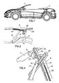
- Figure 1 shows an automobile, whose roof comprises three independent rigid transverse parts, a fixed front one, indicated by number 1 including the front windshield, an intermediate mobile part 2, defining the central area of the roof, and a back swinging part 3 which extends to the trunk and includes the rear windshield.
- the intermediate part 2 and back part 3 can move between a completely closed position, shown in figure 1 , in which they are consecutively coupled, and an open position, shown in figure 9 , in which the car roof is lowered down completely and in which the intermediate part 2 is attached on top of the back part 3 and they are both folded on top of the back part in short wheelbase automobiles, or in an intermediate area between the rear seats and the trunk when the length of the automobile allows it.
- the shift from one position to the other is carried out first folding the intermediate part of the roof, which is performed in two movements, a slight rotation, which can be similar to a small elevation movement, which enables to unstuck the intermediate part 2 of the roof from the front part 1 and the back part 3, represented in figure 3 , and a second movement, which consists of a backward movement, with a slightly curve path, until it is on top of the back part 3 of the roof, as shown in figure 5 .
- the back part of the roof 3 swings downwardly, around the articulation axis 5 perpendicular to the longitudinal axis of the vehicle, with the intermediate part 2 attached thereto, attaining a total superposition of both parts and the folding thereof on the back area of the seats, in the position shown in figure 7 , in which the automobile roof is completely lowered down.
- the intermediate part 2 of the roof is connected to the back part by means of a mechanism, indicated by number 6, figure 1 , while the back part 3 of the roof is connected to the automobile structure through the spin axis 5 and through an action mechanism indicated by number 7.
- the mechanism that connects the intermediate part 2 with the back part 3 and through which the first elevation of the intermediate part and the backward movement of said part are produced comprises, on each side of the automobile, a main bar 8, a rotation centering device 9, which is integral to the back part 3 of the roof, and a secondary bar 10 which is also integral to the back part 3 of the roof.
- the mechanism is completed by a hydraulic cylinder 11 to activate the main bar 8 which is articulated by its lower end to the structure of the automobile.
- the secondary bar 10 is slightly arched and has on one of its sides, as clearly shown in figures 11 to 13 and 15 , a longitudinal channel 12 and through the longitudinal walls of said channel there is a back lower outlet 13 and a front upper outlet 14. On the opposite side of said bar there protrudes an axis 15 on which a square 16 is mounted, which can rotate.
- Figure 14 shows a perspective view of the main bar 8 including a straight front section 17 and a curve back section 18.
- the straight front section 17 branches into two arms, indicated by numbers 19 and 20, which articulate at their free end, through corresponding arms 21 and 22, with the ends of the corresponding side of the intermediate part of the roof 2, as indicated with the same references in figures 1 and 2 .
- From the curve back section 18 of the arm there protrude three lateral pivots, a central one 23, through which the main arm 8 is connected to the rotation centering device 9 during the swinging phase of the main bar 8, as it will be indicated later, and two ends, indicated with numbers 24 and 25, through which this main arm will connect to the secondary bar 10, during the longitudinal movement phase of the central part 2 of the roof, as it will be indicated below.
- the back pivot 25 the main bar is articulated to the cylinder 11.
- the back part 2 of the roof is connected to the structure of the vehicle through the previously described articulation axis 5 and an action mechanism 7, which, as can be seen in figures 4, 6 and 9 to 13 , comprises a secondary bar 10, which is fixed to each side of the back part 3 of the roof, a hydraulic action cylinder 27, articulated to the bar 10 through the axis 15 thereof, and a runner 28 inside which the square 16 of the main bar is housed, figure 15 .
- the rotation centering device 9, as seen in figure 4 consists of a part comprising an approximately horizontal groove 30, in which the central pivot 23 of the curve section 23 of the main arm 8 is housed, during the initial elevation phase of the central part 2 of the roof.
- Figures 11, 12 and 13 show the connection and coupling of the different components of the action mechanisms of the central and back parts of the roof.
- a piston 11 When the switch which activates the mechanism opening the convertible roof is pressed, a piston 11 is activated, said piston is joined to the free end of the arched part 18 of the main bar through an external pivot 25.
- the activation of the piston 11 supposes the retraction thereof, producing a clockwise turning of the main bar, when rotating around the central pivot 23, which is inside the channel 30 of the rotation centering device 9. This movement enables to unstuck the central part of the roof 2 from the front part 1 and back part 3 thereof.
- Figure 3 shows when the central part of the roof starts to be unstuck, occupying the mechanism the position of figure 4 .
- the cylinder 11 continues with the retraction and at few degrees of rotation of the main bar 8, the lugs 24 and 25 penetrate into the channel 12 of the secondary bar 10, through the openings 13 and 14, as shown in figure 17 .
- the main bar 8 through the arms 19 and 20 drives the central part 2 of the roof, moving it backwards.
- the piston 11 continues acting and the main bar 8 moves in a parallel path to the profile of the car roof.
- the central part 2 of the roof be located just on top of the back part 3, both with the same inclination, as shown in figure 5 , the action mechanisms occupying the position shown in figure 6 .
- the piston 11 stops acting and the activation of the piston 27 starts, which, like the piston 11, is articulated in its lower part to the structure of the automobile, while in its upper part it is articulated to the secondary bar 10 through the axis 15 thereof, figures 10 and 12 .
- the piston 27 When the piston 27 is driven downwardly, it causes all elements comprising the action mechanisms to start a downward movement, following a path marked by the runner 28.
- the vertical position of this runner enables the superposed central 2 and back parts 3 of the roof to start an anticlockwise rotation, being the rotation centre the articulation axis 5 of the back part of the roof to the structure of the vehicle.
Landscapes
- Engineering & Computer Science (AREA)
- Mechanical Engineering (AREA)
- Body Structure For Vehicles (AREA)
- Seal Device For Vehicle (AREA)
- Vehicle Step Arrangements And Article Storage (AREA)
Abstract
Description
- The present invention refers to a convertible roof for automobiles which in the closed position defines a continuous rigid roof, while in the open position it is located in the rear part of the automobile interior.
- The invention can be particularly applied to automobiles with four seats, in which the roof, when it occupies the open position is, located in the area intended for the rear seats, transforming the car from a four-seat car with rigid cover into a convertible two-seat car. This occurs in the case of short wheelbase vehicles. When the body of the car is longer, that is to say, when it is a long wheelbase vehicle, a space is created between the rear seats and the trunk which is occupied by the roof in its folded position, so that the vehicle maintains its four seats in its convertible version.
- Four-seat convertible automobiles are well-known, with rigid roof, where the roof is constituted in such a way that in the open position it is housed inside the trunk, occupying it completely, so that this hole or space does not serve its intended purpose.
- The object of the present invention is a convertible automobile, with a rigid roof, which enables to keep the trunk hole or volume free in the open or lowered down position of the roof.
- The convertible roof of the invention comprises three independent rigid transverse parts: a front fixed part which includes the windshield, an intermediate part which defines the central area of the roof, and a back part which extends to the trunk and includes the rear windshield, and the intermediate and back parts can be moved from a closed position, in which they are consecutively coupled next to the front fixed part, and an open position, in which the intermediate part is attached to the back part, and both of them are folded on the back seat area or intermediate area between the seats and the trunk.
- For the intermediate part to be coupled to the back part, said intermediate part makes two movements: a first elevation movement, in which it slightly moves upwards with respect to the front and back parts of the roof, detaching from them, and a second backward movement, with a slightly arched path, at the end of which it is coupled on top of the back part of the roof.
- For this movement to occur, the intermediate part of the roof is related to the back part through a mechanism which can move said intermediate part in height, between the closed position and an elevated position over the back part, and longitudinally, between the elevated part and the back part where it is superimposed over the back part, as indicated above.
- As regards the back part, it is connected to the structure of the vehicle through the articulation axis, perpendicular to the longitudinal axis of the automobile, around which it can swing between an elevated position, corresponding to the closed position of the roof, and a lower folded position, in which it covers and closes the back seat area in short wheelbase vehicles, or an intermediate area between the back seats and the trunk created due to a bigger length in long wheelbase vehicles. To that end, this back position is also connected to the vehicle structure by means of a mechanism which produces the swinging of said back part, together with the central part attached thereto.
- The kinematics of the total mechanism is based on three fundamental movements, the first one consists of a small clockwise rotation of the intermediate part of the roof which causes a slight elevation thereof, the second one consists of a translation of this intermediate part towards the back, with a slight curve path, so that it moves in X and Z coordinates, while the third movement consists of a rotation centered in the articulation axis between the back part of the roof and the structure of the vehicle. In this movement the two juxtaposed mobile parts of the roof, the intermediate part and the back part, move, the back part of the roof being hidden and the intermediate part of the roof being visible, which turns into and acts as a cover for housing the convertible roof.
- The mechanism in charge of moving the intermediate part in height and in longitudinal direction towards the back comprises, on each side of the vehicle, a main bar which supports said intermediate part, a rotation centering device for said main bar, which is integral to the back part of the roof and causes the swinging of said main bar, up to the elevation of the main part of the roof, and a secondary bar which is integral to the back part of the roof and constitutes a curve guide on which the main bar can be coupled, when it stops swinging over the rotation centering device, as well as its movement along said guide, to longitudinally move the central part of the roof until it is located on top of the back part.
- The main bar, which is a part of the mechanism described above, has a straight front section and a curve back section. The straight front section branches into two end arms of different length which articulate at their ends to the front and back ends of the corresponding side of the central part of the roof. The curve back part of the main bar is articulated at its free end to an action cylinder, through which both aforementioned movements of the central part of the roof are carried out. The cylinder is articulated at its lower end to the structure of the automobile.
- The curve back section of the main bar has three lateral pivots, a central one through which it connects to the rotation centering device during the swinging phase of said main bar, and two ends through which the main bar connects to the guide of the secondary bar, during the phase of longitudinal movement of the central part of the roof.
- The rotation centering device mentioned above consists of a part fixed to the back part of the roof, on each side thereof, and comprises an approximately horizontal groove, along which the central pivot of the curve section of the main bar moves, during its swinging, to cause the first elevation movement of the central part of the roof.
- The secondary bar is slightly arched and has laterally a longitudinal channel where the end pivots of the curved section of the main bar are inserted, to define the guide of said bar and the anchoring thereof at the end of its longitudinal movement. The aforementioned longitudinal channel has on its longitudinal walls a front lower outlet and a back upper outlet, to which the end pivot of the curve side of the main bar are opposed, until the swinging movement ends, and at this point the pivots are inserted in the channel through the aforementioned outlets, to move along the aforementioned channel and form together the guide leading to the central part of the roof in its longitudinal movement, until it is located on top of the back part of the roof.
- As regards the mechanism which causes the swinging of the back part of the roof, it comprises an action cylinder, which is articulated in its lower part to the structure of the vehicle and in its upper part to the secondary bar through a pivot laterally protruding from said bar, by the opposite side to that occupied by the longitudinal channel thereof. This pivot has on its base a square, rotating around the pivot. The square is housed in a runner which drives the movement of the secondary bar, together with the main bar associated to it, during the swinging of the back part of the roof, from the closed position to the completely open position, in which it is completely folded on the back part of the vehicle interior.
- The following is a more detailed description of the roof of the invention, so that its constitution and characteristics can be better understood, with reference to the attached drawings, presented as a non-limiting example of an embodiment.
-
-
Figure 1 is a side elevation view of an automobile, including the roof of the invention, in its closed position. -
Figure 2 shows the position of the action mechanisms in the closed position of the roof offigure 1 . -
Figure 3 is a similar view to that offigure 1 , with the intermediate part of the roof elevated, to initiate its backwards movement. -
Figure 4 is a similar view to that offigure 2 , showing the position of the mechanisms in the position of the roof shown infigure 3 . -
Figure 5 is a similar view to that offigure 3 , showing the intermediate part of the roof located on the back part. -
Figure 6 is a similar view to that offigure 4 , showing the position of the action mechanisms in the position of the roof shown infigure 5 . -
Figure 7 is a similar view to that offigure 5 , showing the convertible roof in its completely open position. -
Figure 8 is a similar view to that offigure 6 , showing the position of the action mechanisms with the roof in the position offigure 7 . -
Figure 9 is a perspective of the action mechanisms of the intermediate and back parts of the roof, taken from the opposite side to the one shown infigure 4 . -
Figure 10 is an upper plan view of the set of mechanisms shown infigure 4 . -
Figures 11, 12 and 13 are sections of the mechanism, taken according to the cut lines XI-XI, XII-XII and XIII-XIII offigure 10 . -
Figure 14 is a perspective of the main bar of the action mechanism of the intermediate part of the roof. -
Figure 15 is a partial perspective of the secondary bar of the action mechanism of the intermediate part of the roof. -
Figure 16 represents the position of the end lugs of the arched rear section of the main bar, in the position of total closure of the roof, shown infigure 1 . -
Figure 17 shows the position of the end lugs of the rear curve section of the main bar, at the end of the elevation movement of the intermediate part of the roof, shown infigure 3 . -
Figure 1 shows an automobile, whose roof comprises three independent rigid transverse parts, a fixed front one, indicated bynumber 1 including the front windshield, an intermediatemobile part 2, defining the central area of the roof, and aback swinging part 3 which extends to the trunk and includes the rear windshield. Theintermediate part 2 andback part 3 can move between a completely closed position, shown infigure 1 , in which they are consecutively coupled, and an open position, shown infigure 9 , in which the car roof is lowered down completely and in which theintermediate part 2 is attached on top of theback part 3 and they are both folded on top of the back part in short wheelbase automobiles, or in an intermediate area between the rear seats and the trunk when the length of the automobile allows it. - The shift from one position to the other is carried out first folding the intermediate part of the roof, which is performed in two movements, a slight rotation, which can be similar to a small elevation movement, which enables to unstuck the
intermediate part 2 of the roof from thefront part 1 and theback part 3, represented infigure 3 , and a second movement, which consists of a backward movement, with a slightly curve path, until it is on top of theback part 3 of the roof, as shown infigure 5 . Finally, the back part of theroof 3, swings downwardly, around thearticulation axis 5 perpendicular to the longitudinal axis of the vehicle, with theintermediate part 2 attached thereto, attaining a total superposition of both parts and the folding thereof on the back area of the seats, in the position shown infigure 7 , in which the automobile roof is completely lowered down. - To produce these movements the
intermediate part 2 of the roof is connected to the back part by means of a mechanism, indicated bynumber 6,figure 1 , while theback part 3 of the roof is connected to the automobile structure through thespin axis 5 and through an action mechanism indicated bynumber 7. - All these mechanism are shown in
figures 4, 6 and9 to 13 . - The mechanism that connects the
intermediate part 2 with theback part 3 and through which the first elevation of the intermediate part and the backward movement of said part are produced, comprises, on each side of the automobile, amain bar 8, a rotation centering device 9, which is integral to theback part 3 of the roof, and asecondary bar 10 which is also integral to theback part 3 of the roof. The mechanism is completed by ahydraulic cylinder 11 to activate themain bar 8 which is articulated by its lower end to the structure of the automobile. - The
secondary bar 10 is slightly arched and has on one of its sides, as clearly shown infigures 11 to 13 and15 , alongitudinal channel 12 and through the longitudinal walls of said channel there is a backlower outlet 13 and a frontupper outlet 14. On the opposite side of said bar there protrudes anaxis 15 on which asquare 16 is mounted, which can rotate. -
Figure 14 shows a perspective view of themain bar 8 including astraight front section 17 and acurve back section 18. Thestraight front section 17 branches into two arms, indicated bynumbers corresponding arms roof 2, as indicated with the same references infigures 1 and 2 . From thecurve back section 18 of the arm there protrude three lateral pivots, a central one 23, through which themain arm 8 is connected to the rotation centering device 9 during the swinging phase of themain bar 8, as it will be indicated later, and two ends, indicated withnumbers secondary bar 10, during the longitudinal movement phase of thecentral part 2 of the roof, as it will be indicated below. Also, through theback pivot 25 the main bar is articulated to thecylinder 11. - The
back part 2 of the roof is connected to the structure of the vehicle through the previously describedarticulation axis 5 and anaction mechanism 7, which, as can be seen infigures 4, 6 and9 to 13 , comprises asecondary bar 10, which is fixed to each side of theback part 3 of the roof, ahydraulic action cylinder 27, articulated to thebar 10 through theaxis 15 thereof, and arunner 28 inside which thesquare 16 of the main bar is housed,figure 15 . - The rotation centering device 9, as seen in
figure 4 , consists of a part comprising an approximatelyhorizontal groove 30, in which thecentral pivot 23 of thecurve section 23 of themain arm 8 is housed, during the initial elevation phase of thecentral part 2 of the roof. -
Figures 11, 12 and 13 show the connection and coupling of the different components of the action mechanisms of the central and back parts of the roof. - When the roof is closed,
figure 1 , the action mechanisms occupy the position offigure 2 , in which thecentral lug 23 of thearched part 18 of themain bar 8 is inside thegroove 30 of therotation centering device 16, while the end lugs 24 and 25 of said arched part of the main bar are outside thechannel 12 of thesecondary bar 10, opposed to thefront 13 andback openings 14, as shown infigure 16 . - When the switch which activates the mechanism opening the convertible roof is pressed, a
piston 11 is activated, said piston is joined to the free end of thearched part 18 of the main bar through anexternal pivot 25. The activation of thepiston 11 supposes the retraction thereof, producing a clockwise turning of the main bar, when rotating around thecentral pivot 23, which is inside thechannel 30 of the rotation centering device 9. This movement enables to unstuck the central part of theroof 2 from thefront part 1 andback part 3 thereof.Figure 3 shows when the central part of the roof starts to be unstuck, occupying the mechanism the position offigure 4 . - The
cylinder 11 continues with the retraction and at few degrees of rotation of themain bar 8, thelugs channel 12 of thesecondary bar 10, through theopenings figure 17 . Next, thepiston 11, which continues to be retracted, makes thecentral lug 23 come out of thegroove 30 of the rotation centering device 9,figure 6 , being themain bar 8 forced to take a curve backward path, defined by thechannel 12 of thesecondary bar 10, with a slight curve. In this way, themain bar 8, through thearms central part 2 of the roof, moving it backwards. Thepiston 11 continues acting and themain bar 8 moves in a parallel path to the profile of the car roof. Thus, it is finally attained that thecentral part 2 of the roof be located just on top of theback part 3, both with the same inclination, as shown infigure 5 , the action mechanisms occupying the position shown infigure 6 . - Once the
main bar 8 reaches the end of the path of thechannel 12 of thesecondary bar 10, thepiston 11 stops acting and the activation of thepiston 27 starts, which, like thepiston 11, is articulated in its lower part to the structure of the automobile, while in its upper part it is articulated to thesecondary bar 10 through theaxis 15 thereof,figures 10 and 12 . - When the
piston 27 is driven downwardly, it causes all elements comprising the action mechanisms to start a downward movement, following a path marked by therunner 28. The vertical position of this runner enables the superposed central 2 andback parts 3 of the roof to start an anticlockwise rotation, being the rotation centre thearticulation axis 5 of the back part of the roof to the structure of the vehicle. Finally, when the square 16,figure 15 , which is mounted in a revolving way on theaxis 15, reaches the lower end of therunner 28, thanks to the possibility of rotation between theaxis 15 and the square 16, it makes therunner 28, when it comes in contact with theback part 3 of the roof, while said part is going down, to turn clockwise and be finally located under said back part of the roof, as shown infigure 8 , being the central and back parts of the roof attached and coupled on top of the rear part of the automobile, as shown infigure 7 .
Claims (7)
- Convertible roof for automobiles, comprising three independent rigid transverse parts, a fixed front part (1), including the front windshield, an intermediate part (2), defining the central area of the roof, and a back part (3) which extends to the trunk and includes the rear windshield, where the intermediate and back parts can move between a closed position, in which they are consecutively coupled, and an open position, in which the intermediate part is attached on top of the back part and they are both folded over the rear seat area, or over an intermediate area between the rear seats and the trunk created due to the bigger length in long wheelbase vehicles; whose intermediate part (2) is connected to the back part by means of a mechanism (6), which can move said intermediate part in height, between the close position and a position elevated over the back part, and longitudinally, between the elevated position and a back position in which it is superposed on top of the back part (3); and whose back part is connected to the structure of the vehicle through a back articulation axis (5), perpendicular to the longitudinal axis of the automobile and through an action mechanism (7), which causes the swinging of said back part, together with the attached central part (2), around the back articulation axis (5), between the close position and the aforementioned folded position, in which it covers and closes the rear seat area.
- Roof according to claim 1, characterized in that the mechanism (6) in charge of moving the intermediate part (2) of the roof in height and longitudinally towards the back comprises, on each side a main bar (8) which supports said intermediate part, a rotation centering device (9) for said main bar, which is integral to the back part (3) of the roof and causes the swinging of said main bar up to the elevation of the central part of the roof, and a secondary bar (10) which is integral to the back part (3) of the roof and defines a curve guide on which the main bar (8) can be coupled, when its swinging over the rotation centering device (9) ends, as well as its movement along it, to longitudinally move the central part (2) of the roof, until it is located on the back part (3).
- Roof according to claim 2, characterized in that the main bar (8) includes a straight front section (19) and a curve back section (18), whose straight front section branches into two end arms (19-20) of different length, which articulate at their ends to the back and front end of the corresponding side of the central part (23) of the roof, and whose curve back section (18) is articulated at its free end to an action cylinder (11) and has three lateral pivots, a central pivot (23) through which it connects to the rotation centering device (9) during the swinging phase of said main bar (8), and two end pivots (24-25) through which it connects to the guide of the secondary bar (10), during the phase of longitudinal movement of the central part of the roof.
- Roof according to claims 2 and 3, characterized in that the aforementioned rotation centering device (9) comprises an approximately horizontal groove (30), along which the central pivot (23) of the curve section (18) of the main bar (8) moves, during its swinging.
- Roof according to claims 2 and 3, characterized in that the secondary bar (10) is arched and has on one of its sides, a longitudinal channel (12) where the end pivots (24-25) of the curved section (18) of the main bar are inserted, to define the guide of said main bar (8) and the anchoring thereof at the end of its longitudinal movement.
- Roof according to claim 5, characterized in that the longitudinal channel (12) of the secondary bar (10) has on its longitudinal walls a lower outlet (13) and an upper outlet (14), to which the end pivots (24-25) of the curve side (18) of the main bar (8) are opposed, whose pivots are inserted in the channel through the aforementioned outlets, when said main bar ends its swinging.
- Roof according to claim 1, characterized in that the mechanism which causes the swinging of the back part (3) of the roof comprises an action cylinder (27) which is articulated in its lower part to the structure of the vehicle and in its upper part to the secondary bar through an axis (15) laterally protruding from said bar, by the opposite side to that occupied by the longitudinal channel (12) thereof, whose axis has on its base a square (16), rotating around the axis, which is housed in a runner (28) which drives the movement of the secondary bar (10), together with the main bar (8) associated to it, during the swinging of the back part of the roof from its elevated closed position to the lower completely open position.
Applications Claiming Priority (1)
| Application Number | Priority Date | Filing Date | Title |
|---|---|---|---|
| ES200801149U ES1068143Y (en) | 2008-05-29 | 2008-05-29 | REMOVABLE CAR ROOF |
Publications (2)
| Publication Number | Publication Date |
|---|---|
| EP2127930A1 true EP2127930A1 (en) | 2009-12-02 |
| EP2127930B1 EP2127930B1 (en) | 2012-01-04 |
Family
ID=39708083
Family Applications (1)
| Application Number | Title | Priority Date | Filing Date |
|---|---|---|---|
| EP09380112A Not-in-force EP2127930B1 (en) | 2008-05-29 | 2009-05-27 | Convertible roof for automobiles |
Country Status (3)
| Country | Link |
|---|---|
| EP (1) | EP2127930B1 (en) |
| AT (1) | ATE539908T1 (en) |
| ES (2) | ES1068143Y (en) |
Citations (3)
| Publication number | Priority date | Publication date | Assignee | Title |
|---|---|---|---|---|
| GB2240519A (en) * | 1990-01-12 | 1991-08-07 | C & C Inc | Multi-position retractable vehicle roof |
| FR2814403A1 (en) * | 2000-09-28 | 2002-03-29 | France Design | RETRACTABLE ROOF IN THE REAR TRUNK OF A VEHICLE |
| DE102006036853A1 (en) * | 2006-08-07 | 2008-02-14 | GM Global Technology Operations, Inc., Detroit | Cabriolet automobile retractable roof has a sliding roof segment and a pivoting roof segment |
-
2008
- 2008-05-29 ES ES200801149U patent/ES1068143Y/en not_active Expired - Fee Related
-
2009
- 2009-05-27 AT AT09380112T patent/ATE539908T1/en active
- 2009-05-27 ES ES09380112T patent/ES2378026T3/en active Active
- 2009-05-27 EP EP09380112A patent/EP2127930B1/en not_active Not-in-force
Patent Citations (3)
| Publication number | Priority date | Publication date | Assignee | Title |
|---|---|---|---|---|
| GB2240519A (en) * | 1990-01-12 | 1991-08-07 | C & C Inc | Multi-position retractable vehicle roof |
| FR2814403A1 (en) * | 2000-09-28 | 2002-03-29 | France Design | RETRACTABLE ROOF IN THE REAR TRUNK OF A VEHICLE |
| DE102006036853A1 (en) * | 2006-08-07 | 2008-02-14 | GM Global Technology Operations, Inc., Detroit | Cabriolet automobile retractable roof has a sliding roof segment and a pivoting roof segment |
Also Published As
| Publication number | Publication date |
|---|---|
| ES2378026T3 (en) | 2012-04-04 |
| EP2127930B1 (en) | 2012-01-04 |
| ATE539908T1 (en) | 2012-01-15 |
| ES1068143U (en) | 2008-09-01 |
| ES1068143Y (en) | 2008-12-01 |
Similar Documents
| Publication | Publication Date | Title |
|---|---|---|
| JP4268762B2 (en) | Retractable roof for hose box, panel truck or station wagon type vehicle | |
| US7735900B2 (en) | Convertible | |
| DE10152944B4 (en) | Hood for a convertible vehicle | |
| JP2002103981A (en) | Storage roof for convertible vehicle | |
| JP2001150956A (en) | Stored type hardtop for automobile, and automobile with hardtop | |
| US6425620B1 (en) | Roof arrangement for a convertible | |
| US7883138B2 (en) | Cabriolet vehicle | |
| DE19932502C2 (en) | Cover device for a convertible top compartment | |
| US20110227365A1 (en) | Retractable vehicle roof apparatus and vehicle having the same | |
| US6796598B2 (en) | Vehicle retractable roof with two pivoting arms | |
| EP1912815B1 (en) | Car with a sun roof | |
| US7344179B2 (en) | Retractable hardtop for a vehicle | |
| EP2127930B1 (en) | Convertible roof for automobiles | |
| CN101870249A (en) | Car with the top that can open and can take in | |
| US6786527B2 (en) | Retractable roof for vehicle, comprising three longitudinal elements | |
| US6767046B1 (en) | Motor vehicle retractable roof, comprising an element articulated to the chassis | |
| DE102004061775A1 (en) | Convertible vehicle with a movable rear shelf | |
| CN101683813B (en) | Car roof overturning device and vehicles provided with same | |
| CN201291740Y (en) | Vehicle roof turning device and vehicle having the device | |
| US20040036314A1 (en) | Vehicle retractable roof with pivoting elements, sliding with two arms | |
| US7204541B2 (en) | Motor vehicle | |
| EP1406777B1 (en) | Retractable hardtop vehicle roof | |
| US7287801B2 (en) | Convertible top mechanism with inwardly articulating rearmost lateral rails | |
| CN101138958B (en) | Convertible | |
| EP2328770B1 (en) | Vehicle roof retracting device and vehicle having the same |
Legal Events
| Date | Code | Title | Description |
|---|---|---|---|
| PUAI | Public reference made under article 153(3) epc to a published international application that has entered the european phase |
Free format text: ORIGINAL CODE: 0009012 |
|
| AK | Designated contracting states |
Kind code of ref document: A1 Designated state(s): AT BE BG CH CY CZ DE DK EE ES FI FR GB GR HR HU IE IS IT LI LT LU LV MC MK MT NL NO PL PT RO SE SI SK TR |
|
| 17P | Request for examination filed |
Effective date: 20100526 |
|
| 17Q | First examination report despatched |
Effective date: 20100621 |
|
| GRAP | Despatch of communication of intention to grant a patent |
Free format text: ORIGINAL CODE: EPIDOSNIGR1 |
|
| GRAS | Grant fee paid |
Free format text: ORIGINAL CODE: EPIDOSNIGR3 |
|
| GRAA | (expected) grant |
Free format text: ORIGINAL CODE: 0009210 |
|
| AK | Designated contracting states |
Kind code of ref document: B1 Designated state(s): AT BE BG CH CY CZ DE DK EE ES FI FR GB GR HR HU IE IS IT LI LT LU LV MC MK MT NL NO PL PT RO SE SI SK TR |
|
| REG | Reference to a national code |
Ref country code: GB Ref legal event code: FG4D |
|
| REG | Reference to a national code |
Ref country code: CH Ref legal event code: EP |
|
| REG | Reference to a national code |
Ref country code: AT Ref legal event code: REF Ref document number: 539908 Country of ref document: AT Kind code of ref document: T Effective date: 20120115 |
|
| REG | Reference to a national code |
Ref country code: IE Ref legal event code: FG4D |
|
| REG | Reference to a national code |
Ref country code: DE Ref legal event code: R096 Ref document number: 602009004519 Country of ref document: DE Effective date: 20120308 |
|
| REG | Reference to a national code |
Ref country code: ES Ref legal event code: FG2A Ref document number: 2378026 Country of ref document: ES Kind code of ref document: T3 Effective date: 20120404 |
|
| REG | Reference to a national code |
Ref country code: NL Ref legal event code: VDEP Effective date: 20120104 |
|
| PG25 | Lapsed in a contracting state [announced via postgrant information from national office to epo] |
Ref country code: SI Free format text: LAPSE BECAUSE OF FAILURE TO SUBMIT A TRANSLATION OF THE DESCRIPTION OR TO PAY THE FEE WITHIN THE PRESCRIBED TIME-LIMIT Effective date: 20120104 |
|
| LTIE | Lt: invalidation of european patent or patent extension |
Effective date: 20120104 |
|
| PG25 | Lapsed in a contracting state [announced via postgrant information from national office to epo] |
Ref country code: NO Free format text: LAPSE BECAUSE OF FAILURE TO SUBMIT A TRANSLATION OF THE DESCRIPTION OR TO PAY THE FEE WITHIN THE PRESCRIBED TIME-LIMIT Effective date: 20120404 Ref country code: HR Free format text: LAPSE BECAUSE OF FAILURE TO SUBMIT A TRANSLATION OF THE DESCRIPTION OR TO PAY THE FEE WITHIN THE PRESCRIBED TIME-LIMIT Effective date: 20120104 Ref country code: IS Free format text: LAPSE BECAUSE OF FAILURE TO SUBMIT A TRANSLATION OF THE DESCRIPTION OR TO PAY THE FEE WITHIN THE PRESCRIBED TIME-LIMIT Effective date: 20120504 Ref country code: LT Free format text: LAPSE BECAUSE OF FAILURE TO SUBMIT A TRANSLATION OF THE DESCRIPTION OR TO PAY THE FEE WITHIN THE PRESCRIBED TIME-LIMIT Effective date: 20120104 Ref country code: BE Free format text: LAPSE BECAUSE OF FAILURE TO SUBMIT A TRANSLATION OF THE DESCRIPTION OR TO PAY THE FEE WITHIN THE PRESCRIBED TIME-LIMIT Effective date: 20120104 Ref country code: BG Free format text: LAPSE BECAUSE OF FAILURE TO SUBMIT A TRANSLATION OF THE DESCRIPTION OR TO PAY THE FEE WITHIN THE PRESCRIBED TIME-LIMIT Effective date: 20120404 Ref country code: NL Free format text: LAPSE BECAUSE OF FAILURE TO SUBMIT A TRANSLATION OF THE DESCRIPTION OR TO PAY THE FEE WITHIN THE PRESCRIBED TIME-LIMIT Effective date: 20120104 |
|
| PG25 | Lapsed in a contracting state [announced via postgrant information from national office to epo] |
Ref country code: GR Free format text: LAPSE BECAUSE OF FAILURE TO SUBMIT A TRANSLATION OF THE DESCRIPTION OR TO PAY THE FEE WITHIN THE PRESCRIBED TIME-LIMIT Effective date: 20120405 Ref country code: FI Free format text: LAPSE BECAUSE OF FAILURE TO SUBMIT A TRANSLATION OF THE DESCRIPTION OR TO PAY THE FEE WITHIN THE PRESCRIBED TIME-LIMIT Effective date: 20120104 Ref country code: LV Free format text: LAPSE BECAUSE OF FAILURE TO SUBMIT A TRANSLATION OF THE DESCRIPTION OR TO PAY THE FEE WITHIN THE PRESCRIBED TIME-LIMIT Effective date: 20120104 Ref country code: PL Free format text: LAPSE BECAUSE OF FAILURE TO SUBMIT A TRANSLATION OF THE DESCRIPTION OR TO PAY THE FEE WITHIN THE PRESCRIBED TIME-LIMIT Effective date: 20120104 Ref country code: PT Free format text: LAPSE BECAUSE OF FAILURE TO SUBMIT A TRANSLATION OF THE DESCRIPTION OR TO PAY THE FEE WITHIN THE PRESCRIBED TIME-LIMIT Effective date: 20120504 |
|
| REG | Reference to a national code |
Ref country code: AT Ref legal event code: MK05 Ref document number: 539908 Country of ref document: AT Kind code of ref document: T Effective date: 20120104 |
|
| PG25 | Lapsed in a contracting state [announced via postgrant information from national office to epo] |
Ref country code: CY Free format text: LAPSE BECAUSE OF FAILURE TO SUBMIT A TRANSLATION OF THE DESCRIPTION OR TO PAY THE FEE WITHIN THE PRESCRIBED TIME-LIMIT Effective date: 20120104 |
|
| PG25 | Lapsed in a contracting state [announced via postgrant information from national office to epo] |
Ref country code: SE Free format text: LAPSE BECAUSE OF FAILURE TO SUBMIT A TRANSLATION OF THE DESCRIPTION OR TO PAY THE FEE WITHIN THE PRESCRIBED TIME-LIMIT Effective date: 20120104 Ref country code: RO Free format text: LAPSE BECAUSE OF FAILURE TO SUBMIT A TRANSLATION OF THE DESCRIPTION OR TO PAY THE FEE WITHIN THE PRESCRIBED TIME-LIMIT Effective date: 20120104 Ref country code: EE Free format text: LAPSE BECAUSE OF FAILURE TO SUBMIT A TRANSLATION OF THE DESCRIPTION OR TO PAY THE FEE WITHIN THE PRESCRIBED TIME-LIMIT Effective date: 20120104 Ref country code: DK Free format text: LAPSE BECAUSE OF FAILURE TO SUBMIT A TRANSLATION OF THE DESCRIPTION OR TO PAY THE FEE WITHIN THE PRESCRIBED TIME-LIMIT Effective date: 20120104 Ref country code: CZ Free format text: LAPSE BECAUSE OF FAILURE TO SUBMIT A TRANSLATION OF THE DESCRIPTION OR TO PAY THE FEE WITHIN THE PRESCRIBED TIME-LIMIT Effective date: 20120104 |
|
| PLBE | No opposition filed within time limit |
Free format text: ORIGINAL CODE: 0009261 |
|
| STAA | Information on the status of an ep patent application or granted ep patent |
Free format text: STATUS: NO OPPOSITION FILED WITHIN TIME LIMIT |
|
| PG25 | Lapsed in a contracting state [announced via postgrant information from national office to epo] |
Ref country code: SK Free format text: LAPSE BECAUSE OF FAILURE TO SUBMIT A TRANSLATION OF THE DESCRIPTION OR TO PAY THE FEE WITHIN THE PRESCRIBED TIME-LIMIT Effective date: 20120104 |
|
| REG | Reference to a national code |
Ref country code: DE Ref legal event code: R119 Ref document number: 602009004519 Country of ref document: DE |
|
| 26N | No opposition filed |
Effective date: 20121005 |
|
| PG25 | Lapsed in a contracting state [announced via postgrant information from national office to epo] |
Ref country code: MC Free format text: LAPSE BECAUSE OF NON-PAYMENT OF DUE FEES Effective date: 20120531 |
|
| PGFP | Annual fee paid to national office [announced via postgrant information from national office to epo] |
Ref country code: IT Payment date: 20120531 Year of fee payment: 4 |
|
| PG25 | Lapsed in a contracting state [announced via postgrant information from national office to epo] |
Ref country code: AT Free format text: LAPSE BECAUSE OF FAILURE TO SUBMIT A TRANSLATION OF THE DESCRIPTION OR TO PAY THE FEE WITHIN THE PRESCRIBED TIME-LIMIT Effective date: 20120104 |
|
| REG | Reference to a national code |
Ref country code: DE Ref legal event code: R097 Ref document number: 602009004519 Country of ref document: DE Effective date: 20121005 |
|
| REG | Reference to a national code |
Ref country code: IE Ref legal event code: MM4A |
|
| PG25 | Lapsed in a contracting state [announced via postgrant information from national office to epo] |
Ref country code: MK Free format text: LAPSE BECAUSE OF FAILURE TO SUBMIT A TRANSLATION OF THE DESCRIPTION OR TO PAY THE FEE WITHIN THE PRESCRIBED TIME-LIMIT Effective date: 20120104 |
|
| REG | Reference to a national code |
Ref country code: FR Ref legal event code: ST Effective date: 20130131 |
|
| REG | Reference to a national code |
Ref country code: DE Ref legal event code: R119 Ref document number: 602009004519 Country of ref document: DE Effective date: 20121201 |
|
| PG25 | Lapsed in a contracting state [announced via postgrant information from national office to epo] |
Ref country code: IE Free format text: LAPSE BECAUSE OF NON-PAYMENT OF DUE FEES Effective date: 20120527 Ref country code: FR Free format text: LAPSE BECAUSE OF NON-PAYMENT OF DUE FEES Effective date: 20120531 |
|
| PG25 | Lapsed in a contracting state [announced via postgrant information from national office to epo] |
Ref country code: DE Free format text: LAPSE BECAUSE OF NON-PAYMENT OF DUE FEES Effective date: 20121201 |
|
| PG25 | Lapsed in a contracting state [announced via postgrant information from national office to epo] |
Ref country code: MT Free format text: LAPSE BECAUSE OF FAILURE TO SUBMIT A TRANSLATION OF THE DESCRIPTION OR TO PAY THE FEE WITHIN THE PRESCRIBED TIME-LIMIT Effective date: 20120104 |
|
| REG | Reference to a national code |
Ref country code: ES Ref legal event code: FD2A Effective date: 20131018 |
|
| PG25 | Lapsed in a contracting state [announced via postgrant information from national office to epo] |
Ref country code: ES Free format text: LAPSE BECAUSE OF NON-PAYMENT OF DUE FEES Effective date: 20120528 |
|
| REG | Reference to a national code |
Ref country code: CH Ref legal event code: PL |
|
| GBPC | Gb: european patent ceased through non-payment of renewal fee |
Effective date: 20130527 |
|
| PG25 | Lapsed in a contracting state [announced via postgrant information from national office to epo] |
Ref country code: LI Free format text: LAPSE BECAUSE OF NON-PAYMENT OF DUE FEES Effective date: 20130531 Ref country code: CH Free format text: LAPSE BECAUSE OF NON-PAYMENT OF DUE FEES Effective date: 20130531 |
|
| PG25 | Lapsed in a contracting state [announced via postgrant information from national office to epo] |
Ref country code: IT Free format text: LAPSE BECAUSE OF NON-PAYMENT OF DUE FEES Effective date: 20130527 |
|
| PG25 | Lapsed in a contracting state [announced via postgrant information from national office to epo] |
Ref country code: TR Free format text: LAPSE BECAUSE OF FAILURE TO SUBMIT A TRANSLATION OF THE DESCRIPTION OR TO PAY THE FEE WITHIN THE PRESCRIBED TIME-LIMIT Effective date: 20120104 Ref country code: GB Free format text: LAPSE BECAUSE OF NON-PAYMENT OF DUE FEES Effective date: 20130527 |
|
| PG25 | Lapsed in a contracting state [announced via postgrant information from national office to epo] |
Ref country code: LU Free format text: LAPSE BECAUSE OF NON-PAYMENT OF DUE FEES Effective date: 20120527 |
|
| PG25 | Lapsed in a contracting state [announced via postgrant information from national office to epo] |
Ref country code: HU Free format text: LAPSE BECAUSE OF FAILURE TO SUBMIT A TRANSLATION OF THE DESCRIPTION OR TO PAY THE FEE WITHIN THE PRESCRIBED TIME-LIMIT Effective date: 20090527 |