EP2127912A1 - Pneumatic tire - Google Patents
Pneumatic tire Download PDFInfo
- Publication number
- EP2127912A1 EP2127912A1 EP08721947A EP08721947A EP2127912A1 EP 2127912 A1 EP2127912 A1 EP 2127912A1 EP 08721947 A EP08721947 A EP 08721947A EP 08721947 A EP08721947 A EP 08721947A EP 2127912 A1 EP2127912 A1 EP 2127912A1
- Authority
- EP
- European Patent Office
- Prior art keywords
- tire
- vehicle
- bead filler
- outer side
- filler sheet
- Prior art date
- Legal status (The legal status is an assumption and is not a legal conclusion. Google has not performed a legal analysis and makes no representation as to the accuracy of the status listed.)
- Granted
Links
Images

Classifications
-
- B—PERFORMING OPERATIONS; TRANSPORTING
- B60—VEHICLES IN GENERAL
- B60C—VEHICLE TYRES; TYRE INFLATION; TYRE CHANGING; CONNECTING VALVES TO INFLATABLE ELASTIC BODIES IN GENERAL; DEVICES OR ARRANGEMENTS RELATED TO TYRES
- B60C13/00—Tyre sidewalls; Protecting, decorating, marking, or the like, thereof
-
- B—PERFORMING OPERATIONS; TRANSPORTING
- B60—VEHICLES IN GENERAL
- B60C—VEHICLE TYRES; TYRE INFLATION; TYRE CHANGING; CONNECTING VALVES TO INFLATABLE ELASTIC BODIES IN GENERAL; DEVICES OR ARRANGEMENTS RELATED TO TYRES
- B60C15/00—Tyre beads, e.g. ply turn-up or overlap
- B60C15/0009—Tyre beads, e.g. ply turn-up or overlap features of the carcass terminal portion
- B60C15/0036—Tyre beads, e.g. ply turn-up or overlap features of the carcass terminal portion with high ply turn-up, i.e. folded around the bead core and terminating radially above the point of maximum section width
- B60C15/0045—Tyre beads, e.g. ply turn-up or overlap features of the carcass terminal portion with high ply turn-up, i.e. folded around the bead core and terminating radially above the point of maximum section width with ply turn-up up to the belt edges, i.e. folded around the bead core and extending to the belt edges
-
- B—PERFORMING OPERATIONS; TRANSPORTING
- B60—VEHICLES IN GENERAL
- B60C—VEHICLE TYRES; TYRE INFLATION; TYRE CHANGING; CONNECTING VALVES TO INFLATABLE ELASTIC BODIES IN GENERAL; DEVICES OR ARRANGEMENTS RELATED TO TYRES
- B60C15/00—Tyre beads, e.g. ply turn-up or overlap
- B60C15/06—Flipper strips, fillers, or chafing strips and reinforcing layers for the construction of the bead
-
- B—PERFORMING OPERATIONS; TRANSPORTING
- B60—VEHICLES IN GENERAL
- B60C—VEHICLE TYRES; TYRE INFLATION; TYRE CHANGING; CONNECTING VALVES TO INFLATABLE ELASTIC BODIES IN GENERAL; DEVICES OR ARRANGEMENTS RELATED TO TYRES
- B60C19/00—Tyre parts or constructions not otherwise provided for
- B60C19/001—Tyres requiring an asymmetric or a special mounting
-
- B—PERFORMING OPERATIONS; TRANSPORTING
- B60—VEHICLES IN GENERAL
- B60C—VEHICLE TYRES; TYRE INFLATION; TYRE CHANGING; CONNECTING VALVES TO INFLATABLE ELASTIC BODIES IN GENERAL; DEVICES OR ARRANGEMENTS RELATED TO TYRES
- B60C9/00—Reinforcements or ply arrangement of pneumatic tyres
- B60C9/02—Carcasses
- B60C9/14—Carcasses built-up with sheets, webs, or films of homogeneous material, e.g. synthetics, sheet metal, rubber
Definitions
- the present invention relates to a pneumatic tire having improved performance in running at a relatively high speed.
- Examples of such techniques as described above include a tire inner structure and/or a tire sectional shape where, on the basis of a fact that a relatively large lateral force is exerted on a tire mounted on the outer side of a cornering, in particular, on the vehicle outer side portion of said tire when a portion of the chassis on the outer side of a cornering dives under the conditions described above, rigidity of a sidewall portion on the vehicle outer side of a tire mounted on a vehicle is enhanced to resist the aforementioned lateral force to stabilize the posture of the vehicle.
- examples of the techniques to improve riding comfort include a tire sectional configuration where, on the basis of a discovery that deformation caused in a tire as a result of vertical movement of a vehicle is particularly significant on the vehicle inner side of the tire mounted on the vehicle in a vehicle provided with a negative camber, a radius of curvature of the inner side portion of a tire mounted on a vehicle is decreased to improve attenuation performance of vertical vibration.
- An object of the present invention is to provide a pneumatic tire capable of effectively making the conflicting performances, i.e. driving stability and riding comfort, compatible with each other by enhancing rigidity of the vehicle inner side portion of a tire mounted on a vehicle.
- the vehicle outer side portion of the tire mounted on a vehicle When a case where irregularities on a road hit the vehicle outer side portion of a tire mounted on a vehicle is compared with a case where irregularities on a road hit the vehicle inner side portion of the same tire, provided that the dimensions of the irregularities are the same in both cases, the vehicle outer side portion of the tire mounted on a vehicle, having a larger proportion of load exerted thereon, receive larger vibrations than the vehicle inner side portion of the tire because a wheel mounting support portion (a hub surface of a wheel) is provided in an offset manner in the majority of vehicles. Accordingly, it is assumed that suppressing a vibration input to the vehicle outer side portion of a tire mounted on a vehicle is more effective than suppressing a vibration input to the vehicle inner side portion of the same tire.
- a pneumatic tire comprises: a pair of bead cores; a carcass extending over the pair of bead cores, with respective end portions thereof being turned up around the bead cores; a bead filler provided between a main body of the carcass extending from one bead core to the other bead core and a turned-up portion of the carcass turned up around the bead core, the bead filler extending from the bead core toward the outer side in the radial direction; a belt provided on the outer peripheral side of a crown region of the carcass; a tread rubber disposed on the outer peripheral side of the belt; and a sidewall rubber disposed on the outer side in the widthwise direction of the carcass, wherein a vehicle inner side bead filler sheet having a sheet-like shape is provided at a tire side portion which is positioned on the vehicle inner side when the tire is mounted on a vehicle, in
- "being provided at a tire side portion which is positioned on the vehicle inner side when the tire is mounted on a vehicle” represents not only provision of the bead filler sheet at the outer surface of the carcass but also provision thereof at a position on the outer side in the radial direction of the sidewall rubber.
- the vehicle inner side bead filler sheet is provided for a reinforcement purpose at a tire side portion which is positioned on the vehicle inner side when the tire is mounted on a vehicle. Accordingly, the rigidity of the tire side portion on the vehicle inner side can be made relatively higher than the rigidity of the tire side portion on the vehicle outer side.
- a lateral force acting in a positive direction is exerted on a vehicle outer side wheel in a cornering situation. Therefore, by setting such a wheel to have negative camber in advance, good ground contact property in a cornering situation is ensured.
- a ground contact pressure at the vehicle inner side portion of a tread of the tire mounted on a vehicle when the vehicle inner side portion is in contact with the ground is higher than a ground contact pressure at the vehicle outer side portion of the tread when the vehicle outer side portion is in contact with the ground, whereby the steering force intended by a driver can be easily transmitted to a road surface and driving stability is improved.
- rigidity of the tire side portion on the vehicle outer side is made relatively small than rigidity of the tire side portion on the vehicle inner side, i.e. increase in rigidity of the tire side portion on the vehicle outer side, which receives relatively large input from irregularities on a road surface, is suppressed, whereby vibrations caused to the tire and eventually the vehicle can be alleviated.
- the pneumatic tire of the first aspect of the present invention is characterized in that a vehicle outer side bead filler sheet having a sheet-like shape is provided at a tire side portion which is positioned on the vehicle outer side when the tire is mounted on a vehicle, in a manner that the bead filler sheet is disposed from the inner side toward the outer side in the tire radial direction, and, provided that the height of the vehicle inner side bead filler sheet from a reference line passing through a rim diameter line in use for measuring a tire sectional height and in parallel to the tire center axis, to the outer end in the tire radial direction of the vehicle inner side bead filler sheet, measured from the reference line toward the outer side in the tire radial direction, is H1 and the height of the vehicle outer side bead filler sheet from the reference line to the outer end in the tire radial direction of the vehicle outer side bead filler sheet, measured from the reference line toward the outer side in the tire radial direction, measured from the reference line toward the outer side
- high driving stability can be obtained by setting H1/H2 in the range of 105 to 160%.
- H1/H2 is smaller than 105%, rigidity of the tire side portion on the vehicle inner side is not sufficiently enhanced, whereby driving stability is not sufficiently improved.
- H1/H2 exceeds 160%, rigidity of the tire side portion on the vehicle inner side is too high, whereby riding comfort deteriorates.
- the pneumatic tire of the second aspect of the present invention is characterized in that the vehicle inner side bead filler sheet and the vehicle outer side bead filler sheet are formed of rubber, respectively, and rubber hardness of the vehicle inner side bead filler sheet is higher than rubber hardness of the vehicle outer side bead filler sheet.
- rigidity of the tire side portion on the vehicle inner side can be enhanced by setting rubber hardness of the vehicle inner side bead filler sheet higher than rubber hardness of the vehicle outer side bead filler sheet, so that good driving stability can be obtained.
- the pneumatic tire of the second or third aspect of the present invention is characterized in that the vehicle inner side bead filler sheet and the vehicle outer side bead filler sheet are formed of rubber of the same type as that of the bead filler.
- rigidity of the tire side portions can be enhanced by forming the vehicle inner side bead filler sheet and the vehicle outer side bead filler sheet by rubber of the same type as the rubber of the bead filler. Further, since the number of types of rubber species need not be increased in production, cost can be reduced.
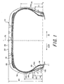
- FIG. 1 is a sectional view cut along the center axis of a pneumatic tire according to an embodiment of the present invention.
- FIG. 2 is a sectional view cut along the center axis of a pneumatic tire according to another embodiment of the present invention.
- the pneumatic tire 10 of the present embodiment assembled with a rim 11, has a radial structure including:
- a bead filler 30 extending toward the outer side in the tire radial direction of the bead core 14 is provided between a main body 16A of the carcass 16 straddling over one bead core 14 and the other bead core 14 and each turned-up portion 16B of the carcass 16 turned up around the corresponding bead core 14 to close the corresponding end portion of the carcass.
- the thickness of the bead filler 30 gradually decreases toward the outer side in the tire radial direction.
- the bead filler 30 is formed of rubber having higher rubber hardness than the sidewall rubber 28.
- a vehicle inner side bead filler sheet 32 IN is attached to a tire side portion on the vehicle inner side such that the vehicle inner side bead filler sheet is firmly adhered to the outer surface of the carcass 16.
- a vehicle outer side bead filler sheet 32 OUT is attached to a tire side portion on the vehicle outer side such that the vehicle outer side bead filler sheet is firmly adhered to the outer surface of the carcass 16.
- the vehicle inner side bead filler sheet 32 IN and the vehicle outer side bead filler sheet 32 OUT each have a constant thickness and are formed of rubber having high hardness.
- the rubbers constituting the vehicle inner side bead filler sheet 32 IN and the vehicle outer side bead filler sheet 32 OUT respectively are preferably rubber of the same type as the rubber constituting the bead filler 30.
- the rubber constituting the vehicle inner side bead filler sheet 32 IN and the rubber constituting the vehicle outer side bead filler sheet 32 OUT are the same rubber as that constituting the bead filler 30.
- each of the vehicle inner side bead filler sheet 32 IN and the vehicle outer side bead filler sheet 32 OUT is preferably in the range of 0.5 to 2.0 mm, and the thickness of the sidewall rubber 28 is preferably in the range of 1.5 to 6.0 mm.
- the inner end in the tire radial direction of the vehicle inner side bead filler sheet 32 IN and the inner end in the tire radial direction of the vehicle outer side bead filler sheet 32 OUT are positioned on the inner side in the radial direction than the outer end in the tire radial direction of the adjacent bead filler 30, respectively. Due to this, a portion of a tire radial direction inner part of the vehicle inner side bead filler sheet 32 IN and a portion of a tire radial direction inner part of the vehicle outer side bead filler sheet 32 OUT overlap with a portion of a tire radial direction outer part of the adjacent bead filler 30 by way of the turned-up portion 16B of the carcass 16, respectively. Accordingly, rigidity of the bead portion 12, in particular, is enhanced, whereby driving stability is improved.
- the tire sectional height is SH
- the height H1 of the vehicle inner side bead filler sheet is preferably set in the range of 50 to 70% of the tire sectional height SH and H1/H2 is preferably set in the range of 105 to 160%.
- the vehicle inner side bead filler sheet is disposed so as to cover the vicinities of the maximum width position of the tire. Accordingly, the movements in the vertical direction of a running vehicle can be absorbed and rigidity in the lateral and torsional directions is enhanced, whereby driving stability is improved.
- the vehicle inner side bead filler sheet 32 IN is provided at the tire side portion which is positioned on the vehicle inner side when the tire is mounted on a vehicle
- the vehicle outer side bead filler sheet 32 OUT is provided at the tire side portion which is positioned on the vehicle outer side when the tire is mounted on a vehicle
- the height H1 of the vehicle inner side bead filler sheet is set in the range of 50 to 70% of the tire sectional height SH
- H1/H2 is preferably set in the range of 105 to 160%, so that the rigidity of the tire side portion on the vehicle inner side is relatively higher than the rigidity of the tire side portion on the vehicle outer side.
- a steering force intended by a driver can be easily transmitted to a road surface, while increase in rigidity of the tire side portion on the vehicle outer side, which side portion receives relatively large input from irregularities on a road surface, is suppressed, whereby vibrations caused to the tire and eventually the vehicle can be alleviated.
- the height H1 of the vehicle inner side bead filler sheet is less than 50% of the tire sectional height SH, rigidity of the tire side portion on the vehicle inner side is not sufficiently enhanced, whereby driving stability is not sufficiently improved.
- vehicle inner side bead filler sheet 32 IN and the vehicle outer side bead filler sheet 32 OUT are provided in the pneumatic tire 10 of the present embodiment, the vehicle outer side bead filler sheet 32 OUT may be omitted depending on the application, as shown in FIG. 2 .
- the rubbers constituting the vehicle inner side bead filler sheet 32 IN and the vehicle outer side bead filler sheet 32 OUT respectively are rubber of the same type or species in the pneumatic tire 10 of the present embodiment
- the hardness of the rubber constituting the vehicle inner side bead filler sheet 32 IN may be made higher than the hardness of the rubber constituting the vehicle outer side bead filler sheet 32 OUT .
- rigidity of the tire side portion on the vehicle inner side is further enhanced, whereby driving stability can be further improved.
- the tire of Conventional Example has a structure where a bead filler sheet is not disposed therein, the tire of Example 1 has a structure as show in FIG. 2 , the tire of Example 2 has a structure as show in FIG.
- the tire of Comparative Example 1 has a structure in which the vehicle outer side bead filler sheet and the vehicle inner side bead filler sheet are disposed so as to have the same length, respectively, and the tire of Comparative Example 2 has a structure in which the outer end in the tire radial direction of the bead filler is positioned on the outer side in the tire radial direction than the outer end in the tire radial direction of the turned-up portion of the carcass.
- the structures thereof other than the bead filler and the bead filler sheet needed no changes and thus were prepared in accordance with the tires of Examples, respectively.
- the tests were conducted by: running a test vehicle, on a test course including a circular road having relatively long linear portions and a handling-evaluation road having curves ranging from a gentle one to a sharp one, at a speed in the speed range from a relatively low speed to 100 km/h, which would be generally experienced by drivers in public roads; and evaluating driving stability (handle response) and riding comfort by a professional test driver's feeling evaluation.
Landscapes
- Engineering & Computer Science (AREA)
- Mechanical Engineering (AREA)
- Tires In General (AREA)
Abstract
Description
- The present invention relates to a pneumatic tire having improved performance in running at a relatively high speed.
- As a demand for improved tire performance increases, various techniques have been proposed which simultaneously satisfy plural performances which were conventionally regarded as incompatible with each other, such as driving stability, riding comfort, low-level noise, wear resistance performance and the like.
Examples of such techniques include a technique to design a tire to be asymmetrical with respect to the tire equatorial plane. For example, based on a fact that the vehicle inner side and the vehicle outer side of a tire in a state where the tire is mounted on a vehicle make different contributions to the aforementioned plural performances, respectively, there have been proposed a number of techniques to make the inner structure of a tire asymmetrical with respect to the equatorial plane (e.g.JP 63-008005 JP 2003-320821 JP 2005-075295 - Further, needless to say, there are a number of proposals for improvements, which proposals pursue making a tread pattern or a tire sectional shape asymmetrical with respect to the equatorial plane.
The aforementioned techniques to make a tire structure asymmetrical propose separating functions between the vehicle inner side and the vehicle outer side of a tire in a state where the tire is mounted on a vehicle, based on a fact that forces acting on the tire are exerted asymmetrical with respect to the tire equatorial plane, regardless that the tire is running straight or in a cornering situation, as a result that behaviors and alignment of suspension are asymmetrical with respect to the tire equatorial plane in an environment where the tire mounted on a vehicle is used. - Examples of such techniques as described above, e.g. a technique regarding driving stability to improve cornering performance at a relatively large steering angle input at a relatively high speed, include a tire inner structure and/or a tire sectional shape where, on the basis of a fact that a relatively large lateral force is exerted on a tire mounted on the outer side of a cornering, in particular, on the vehicle outer side portion of said tire when a portion of the chassis on the outer side of a cornering dives under the conditions described above, rigidity of a sidewall portion on the vehicle outer side of a tire mounted on a vehicle is enhanced to resist the aforementioned lateral force to stabilize the posture of the vehicle.
- Further, examples of the techniques to improve riding comfort include a tire sectional configuration where, on the basis of a discovery that deformation caused in a tire as a result of vertical movement of a vehicle is particularly significant on the vehicle inner side of the tire mounted on the vehicle in a vehicle provided with a negative camber, a radius of curvature of the inner side portion of a tire mounted on a vehicle is decreased to improve attenuation performance of vertical vibration.
- According to the technique to design an inner structure or a sectional shape of a tire such that rigidity of a sidewall portion is enhanced to resist a lateral force exerted in a cornering situation and make the posture of a vehicle stable to improve driving stability, riding comfort deteriorates due to increase in vertical rigidity of the tire. On the other hand, according to the technique to decrease rigidity of the sidewall portion to absorb an input from irregularities on a road surface to improve riding comfort, the driving stability deteriorates.
In order to make these conflicting performances compatible with each other, there have been proposed a number of asymmetrical configurations and structures for enhancing rigidity of the vehicle outer side portion of a tire in a state where the tire is mounted on a vehicle. However, none of these configurations or structures are satisfactory. - An object of the present invention is to provide a pneumatic tire capable of effectively making the conflicting performances, i.e. driving stability and riding comfort, compatible with each other by enhancing rigidity of the vehicle inner side portion of a tire mounted on a vehicle.
- As a result of various experiments and studies conducted by the inventor, following facts have been known.
The largest factor among the external factors which deteriorate driving stability at a very small steering angle in running straight or riding comfort is irregularities on a road surface which cause a running vehicle to vibrate in any vertical or lateral directions. - When a case where irregularities on a road hit the vehicle outer side portion of a tire mounted on a vehicle is compared with a case where irregularities on a road hit the vehicle inner side portion of the same tire, provided that the dimensions of the irregularities are the same in both cases, the vehicle outer side portion of the tire mounted on a vehicle, having a larger proportion of load exerted thereon, receive larger vibrations than the vehicle inner side portion of the tire because a wheel mounting support portion (a hub surface of a wheel) is provided in an offset manner in the majority of vehicles. Accordingly, it is assumed that suppressing a vibration input to the vehicle outer side portion of a tire mounted on a vehicle is more effective than suppressing a vibration input to the vehicle inner side portion of the same tire.
- In a first aspect of the invention which has been contrived in view of the aforementioned facts, a pneumatic tire comprises: a pair of bead cores; a carcass extending over the pair of bead cores, with respective end portions thereof being turned up around the bead cores; a bead filler provided between a main body of the carcass extending from one bead core to the other bead core and a turned-up portion of the carcass turned up around the bead core, the bead filler extending from the bead core toward the outer side in the radial direction; a belt provided on the outer peripheral side of a crown region of the carcass; a tread rubber disposed on the outer peripheral side of the belt; and a sidewall rubber disposed on the outer side in the widthwise direction of the carcass, wherein a vehicle inner side bead filler sheet having a sheet-like shape is provided at a tire side portion which is positioned on the vehicle inner side when the tire is mounted on a vehicle, in a manner that the bead filler sheet is disposed from the inner side toward the outer side in the tire radial direction, such that rigidity of the tire side portion on the vehicle inner side of the tire is higher than rigidity of a tire side portion which is positioned on the vehicle outer side when the tire is mounted on a vehicle.
In the present invention, "being provided at a tire side portion which is positioned on the vehicle inner side when the tire is mounted on a vehicle" represents not only provision of the bead filler sheet at the outer surface of the carcass but also provision thereof at a position on the outer side in the radial direction of the sidewall rubber. - Next, an operation of the pneumatic tire according to the first aspect of the present invention will be described.
In the pneumatic tire according to the first aspect of the present invention, the vehicle inner side bead filler sheet is provided for a reinforcement purpose at a tire side portion which is positioned on the vehicle inner side when the tire is mounted on a vehicle. Accordingly, the rigidity of the tire side portion on the vehicle inner side can be made relatively higher than the rigidity of the tire side portion on the vehicle outer side. - In a vehicle, a lateral force acting in a positive direction is exerted on a vehicle outer side wheel in a cornering situation. Therefore, by setting such a wheel to have negative camber in advance, good ground contact property in a cornering situation is ensured.
In a case where the pneumatic tire according to the first aspect of the present invention is used for a front wheel, a ground contact pressure at the vehicle inner side portion of a tread of the tire mounted on a vehicle when the vehicle inner side portion is in contact with the ground is higher than a ground contact pressure at the vehicle outer side portion of the tread when the vehicle outer side portion is in contact with the ground, whereby the steering force intended by a driver can be easily transmitted to a road surface and driving stability is improved.
Further, rigidity of the tire side portion on the vehicle outer side is made relatively small than rigidity of the tire side portion on the vehicle inner side, i.e. increase in rigidity of the tire side portion on the vehicle outer side, which receives relatively large input from irregularities on a road surface, is suppressed, whereby vibrations caused to the tire and eventually the vehicle can be alleviated. - Yet further, in the pneumatic tire described above, it suffices that the vehicle inner side bead filler sheet is additionally attached in production of a green tire. Therefore, there is no need to prepare a new mold for the present invention and use of the existing mold suffices.
- In a second aspect of the present invention, the pneumatic tire of the first aspect of the present invention is characterized in that a vehicle outer side bead filler sheet having a sheet-like shape is provided at a tire side portion which is positioned on the vehicle outer side when the tire is mounted on a vehicle, in a manner that the bead filler sheet is disposed from the inner side toward the outer side in the tire radial direction, and, provided that the height of the vehicle inner side bead filler sheet from a reference line passing through a rim diameter line in use for measuring a tire sectional height and in parallel to the tire center axis, to the outer end in the tire radial direction of the vehicle inner side bead filler sheet, measured from the reference line toward the outer side in the tire radial direction, is H1 and the height of the vehicle outer side bead filler sheet from the reference line to the outer end in the tire radial direction of the vehicle outer side bead filler sheet, measured from the reference line toward the outer side in the tire radial direction, is H2, H1/H2 is in the range of 105 to 160%.
- Next, an operation of the pneumatic tire according to the second aspect of the present invention will be described.
In the pneumatic tire according to the second aspect of the present invention, high driving stability can be obtained by setting H1/H2 in the range of 105 to 160%.
In a case where H1/H2 is smaller than 105%, rigidity of the tire side portion on the vehicle inner side is not sufficiently enhanced, whereby driving stability is not sufficiently improved.
In a case where H1/H2 exceeds 160%, rigidity of the tire side portion on the vehicle inner side is too high, whereby riding comfort deteriorates. - In a third aspect of the present invention, the pneumatic tire of the second aspect of the present invention is characterized in that the vehicle inner side bead filler sheet and the vehicle outer side bead filler sheet are formed of rubber, respectively, and rubber hardness of the vehicle inner side bead filler sheet is higher than rubber hardness of the vehicle outer side bead filler sheet.
- Next, an operation of the pneumatic tire according to the third aspect of the present invention will be described.
In the pneumatic tire according to the third aspect of the present invention, rigidity of the tire side portion on the vehicle inner side can be enhanced by setting rubber hardness of the vehicle inner side bead filler sheet higher than rubber hardness of the vehicle outer side bead filler sheet, so that good driving stability can be obtained. - In a fourth aspect of the present invention, the pneumatic tire of the second or third aspect of the present invention is characterized in that the vehicle inner side bead filler sheet and the vehicle outer side bead filler sheet are formed of rubber of the same type as that of the bead filler.
- Next, an operation of the pneumatic tire according to the fourth aspect of the present invention will be described.
In the pneumatic tire according to the fourth aspect of the present invention, rigidity of the tire side portions can be enhanced by forming the vehicle inner side bead filler sheet and the vehicle outer side bead filler sheet by rubber of the same type as the rubber of the bead filler. Further, since the number of types of rubber species need not be increased in production, cost can be reduced. - As described above, according the tire of the present invention, there can be obtained a superior effect that improvements of driving stability and riding comfort can be made compatible with each other.
-
FIG. 1 is a sectional view cut along the center axis of a pneumatic tire according to an embodiment of the present invention.
FIG. 2 is a sectional view cut along the center axis of a pneumatic tire according to another embodiment of the present invention. -
- 10
- Pneumatic tire
- 12
- Bead portion
- 14
- Bead core
- 16
- Carcass
- 18
- Belt
- 24
- Tread rubber
- 28
- Side rubber
- 30
- Bead filler
- 32IN
- Vehicle inner side bead filler sheet
- 32OUT
- Vehicle outer side bead filler sheet
- Hereinafter, a
pneumatic tire 10 according to an embodiment of the present invention will be described in detail with reference to the drawings.
As shown in a sectional view in the tire widthwise direction ofFIG. 1 , thepneumatic tire 10 of the present embodiment, assembled with arim 11, has a radial structure including: - a pair of
bead portions 12; acarcass 16 constituted of at least one (one in the present embodiment) carcass ply extending over the pair ofbead portions 12 in a toroidal shape, with respective end portions thereof being turned up aroundbead cores 14; abelt 18 formed by plural belt layers and provided on the outer peripheral side of a crown region of thecarcass 16; abelt reinforcing layer 20 provided at each side portion on the outer peripheral side of thebelt 18; treadrubber 24 forming atread portion 22 on the outer peripheral side of thebelt reinforcing layer 20; asidewall portion 26; andsidewall rubber 28 disposed on the outer surface side of thecarcass 16 to form the outer side surface of thebead portion 12.
Thereference number 11 A represents a rim flange provided on arim 11. The arrow OUT inFIG. 1 represents a tire portion which is positioned on the vehicle outer side in a state where the tire is mounted on a vehicle and the arrow IN represents a tire portion which is positioned on the vehicle inner side in the same situation. - A
bead filler 30 extending toward the outer side in the tire radial direction of thebead core 14 is provided between amain body 16A of thecarcass 16 straddling over onebead core 14 and theother bead core 14 and each turned-upportion 16B of thecarcass 16 turned up around the correspondingbead core 14 to close the corresponding end portion of the carcass. The thickness of thebead filler 30 gradually decreases toward the outer side in the tire radial direction.
Thebead filler 30 is formed of rubber having higher rubber hardness than thesidewall rubber 28. - A vehicle inner side bead filler sheet 32IN is attached to a tire side portion on the vehicle inner side such that the vehicle inner side bead filler sheet is firmly adhered to the outer surface of the
carcass 16. A vehicle outer side bead filler sheet 32OUT is attached to a tire side portion on the vehicle outer side such that the vehicle outer side bead filler sheet is firmly adhered to the outer surface of thecarcass 16. - The vehicle inner side bead filler sheet 32IN and the vehicle outer side bead filler sheet 32OUT each have a constant thickness and are formed of rubber having high hardness. The rubbers constituting the vehicle inner side bead filler sheet 32IN and the vehicle outer side bead filler sheet 32OUT respectively are preferably rubber of the same type as the rubber constituting the
bead filler 30. In the present embodiment, the rubber constituting the vehicle inner side bead filler sheet 32IN and the rubber constituting the vehicle outer side bead filler sheet 32OUT are the same rubber as that constituting thebead filler 30.
The thickness t of each of the vehicle inner side bead filler sheet 32IN and the vehicle outer side bead filler sheet 32OUT is preferably in the range of 0.5 to 2.0 mm, and the thickness of thesidewall rubber 28 is preferably in the range of 1.5 to 6.0 mm. - The inner end in the tire radial direction of the vehicle inner side bead filler sheet 32IN and the inner end in the tire radial direction of the vehicle outer side bead filler sheet 32OUT are positioned on the inner side in the radial direction than the outer end in the tire radial direction of the
adjacent bead filler 30, respectively.
Due to this, a portion of a tire radial direction inner part of the vehicle inner side bead filler sheet 32IN and a portion of a tire radial direction inner part of the vehicle outer side bead filler sheet 32OUT overlap with a portion of a tire radial direction outer part of theadjacent bead filler 30 by way of the turned-upportion 16B of thecarcass 16, respectively.
Accordingly, rigidity of thebead portion 12, in particular, is enhanced, whereby driving stability is improved. - Provided that the tire sectional height is SH, the height of the vehicle inner side bead filler sheet from the reference line L passing through a rim diameter line in use for measuring the tire sectional height SH and in parallel to the tire center axis, to the outer end in the tire radial direction of the vehicle inner side bead filler sheet 32IN, measured from the reference line L toward the outer side in the tire radial direction, is H1 and the height of the vehicle outer side bead filler sheet from the reference line L to the outer end in the tire radial direction of the vehicle outer side bead filler sheet 32OUT is H2, the height H1 of the vehicle inner side bead filler sheet is smaller than the tire sectional height SH and larger than the height H2 of the vehicle outer side bead filler sheet.
- In the present embodiment, the height H1 of the vehicle inner side bead filler sheet is preferably set in the range of 50 to 70% of the tire sectional height SH and H1/H2 is preferably set in the range of 105 to 160%.
Provided that the distance from the reference line L to the inner end in the tire radial direction of the vehicle inner side bead filler sheet 32IN is h1 and the distance from the reference line L to the inner end in the tire radial direction of the vehicle outer side bead filler sheet 32OUT is h2, h1 = h2 in the present embodiment. - The vehicle inner side bead filler sheet is disposed so as to cover the vicinities of the maximum width position of the tire.
Accordingly, the movements in the vertical direction of a running vehicle can be absorbed and rigidity in the lateral and torsional directions is enhanced, whereby driving stability is improved. - Next, an operation of the
pneumatic tire 10 of the present embodiment will be described. In thepneumatic tire 10 of the present embodiment, the vehicle inner side bead filler sheet 32IN is provided at the tire side portion which is positioned on the vehicle inner side when the tire is mounted on a vehicle, the vehicle outer side bead filler sheet 32OUT is provided at the tire side portion which is positioned on the vehicle outer side when the tire is mounted on a vehicle, the height H1 of the vehicle inner side bead filler sheet is set in the range of 50 to 70% of the tire sectional height SH, and H1/H2 is preferably set in the range of 105 to 160%, so that the rigidity of the tire side portion on the vehicle inner side is relatively higher than the rigidity of the tire side portion on the vehicle outer side. - As a result, a steering force intended by a driver can be easily transmitted to a road surface, while increase in rigidity of the tire side portion on the vehicle outer side, which side portion receives relatively large input from irregularities on a road surface, is suppressed, whereby vibrations caused to the tire and eventually the vehicle can be alleviated.
- In a case where the height H1 of the vehicle inner side bead filler sheet is less than 50% of the tire sectional height SH, rigidity of the tire side portion on the vehicle inner side is not sufficiently enhanced, whereby driving stability is not sufficiently improved.
- In a case where the height H1 of the vehicle inner side bead filler sheet exceeds 70% of the tire sectional height SH, rigidity of the tire side portion on the vehicle inner side is too high, whereby riding comfort deteriorates.
- Next, in a case where H1/H2 is less than 105%, rigidity of the tire side portion on the vehicle inner side is not sufficiently enhanced, whereby driving stability is not sufficiently improved.
- In a case where H1/H2 exceeds 160%, rigidity of the tire side portion on the vehicle inner side is too high, whereby riding comfort deteriorates.
- Although the vehicle inner side bead filler sheet 32IN and the vehicle outer side bead filler sheet 32OUT are provided in the
pneumatic tire 10 of the present embodiment, the vehicle outer side bead filler sheet 32OUT may be omitted depending on the application, as shown inFIG. 2 . - Further, although the rubbers constituting the vehicle inner side bead filler sheet 32IN and the vehicle outer side bead filler sheet 32OUT respectively are rubber of the same type or species in the
pneumatic tire 10 of the present embodiment, the hardness of the rubber constituting the vehicle inner side bead filler sheet 32IN may be made higher than the hardness of the rubber constituting the vehicle outer side bead filler sheet 32OUT. As a result, rigidity of the tire side portion on the vehicle inner side is further enhanced, whereby driving stability can be further improved. - In order to confirm an effect of the present invention, there were prepared: one type of pneumatic tire of Conventional Example; one (two) types of pneumatic tire of Comparative Examples; two types of pneumatic tire of Examples to which the present invention had been applied. Each of these tires was actually mounted on a vehicle and subjected to running tests, and driving stability and riding comfort were compared between the tires.
Specifically, the tire of Conventional Example has a structure where a bead filler sheet is not disposed therein, the tire of Example 1 has a structure as show inFIG. 2 , the tire of Example 2 has a structure as show inFIG. 2(1) , the tire of Comparative Example 1 has a structure in which the vehicle outer side bead filler sheet and the vehicle inner side bead filler sheet are disposed so as to have the same length, respectively, and the tire of Comparative Example 2 has a structure in which the outer end in the tire radial direction of the bead filler is positioned on the outer side in the tire radial direction than the outer end in the tire radial direction of the turned-up portion of the carcass. In Conventional Example and Comparative Examples 1 and 2, the structures thereof other than the bead filler and the bead filler sheet needed no changes and thus were prepared in accordance with the tires of Examples, respectively. - The tests were conducted by: running a test vehicle, on a test course including a circular road having relatively long linear portions and a handling-evaluation road having curves ranging from a gentle one to a sharp one, at a speed in the speed range from a relatively low speed to 100 km/h, which would be generally experienced by drivers in public roads; and evaluating driving stability (handle response) and riding comfort by a professional test driver's feeling evaluation.
- The conditions in the tests are as follows.
Tire size: 225/55R17 Rim size: 7.5J × 17 Test vehicle: "Celsior" manufactured by TOYOTA MOTOR CORPORATION Air pressure of tire: 220 kPa (both front and rear wheels) -
[Table 1] Conventional Example Example 1 Example 2 Comparative Example 1 Comparative Example 2 Absence/presence of bead filler sheet Vehicle outer side Absent Absent Present Present Absent Vehicle inner side Absent Present Present Present Absent Ratio of bead filler sheet height H1/H2 ---- ---- 140% 100% ---- Driving stability 6 6.5 7 7 6 Riding comfort 6 6 6 5.5 5.5 - From the test results, it is understood that the pneumatic tires of Examples to which the present invention has been applied exhibit improvements in both driving stability and riding comfort, as compared with the tires of Conventional Example and Comparative Examples 1 and 2.
Claims (4)
- A pneumatic tire comprising:a pair of bead cores;a carcass extending over the pair of bead cores, with respective end portions thereof being turned up around the bead cores;a bead filler provided between a main body of the carcass extending from one bead core to the other bead core and a turned-up portion of the carcass turned up around the bead core, the bead filler extending from the bead core toward the outer side in the radial direction;a belt provided on the outer peripheral side of a crown region of the carcass;a tread rubber disposed on the outer peripheral side of the belt; anda sidewall rubber disposed on the outer side in the widthwise direction of the carcass,wherein a vehicle inner side bead filler sheet having a sheet-like shape is provided at a tire side portion which is positioned on the vehicle inner side when the tire is mounted on a vehicle, in a manner that the bead filler sheet is disposed from the inner side toward the outer side in the tire radial direction, such that rigidity of the tire side portion on the vehicle inner side of the tire is higher than rigidity of a tire side portion which is positioned on the vehicle outer side when the tire is mounted on a vehicle.
- The pneumatic tire of claim 1, wherein a vehicle outer side bead filler sheet having a sheet-like shape is provided at the tire side portion which is positioned on the vehicle outer side when the tire is mounted on a vehicle, in a manner that the bead filler sheet is disposed from the inner side toward the outer side in the tire radial direction, and
provided that the height of the vehicle inner side bead filler sheet from a reference line passing through a rim diameter line in use for measuring a tire sectional height and in parallel to the tire center axis, to the outer end in the tire radial direction of the vehicle inner side bead filler sheet, measured from the reference line toward the outer side in the tire radial direction, is H1 and the height of the vehicle outer side bead filler sheet from the reference line to the outer end in the tire radial direction of the vehicle outer side bead filler sheet, measured from the reference line toward the outer side in the tire radial direction, is H2, H1/H2 is in the range of 105 to 160%. - The pneumatic tire of claim 2, wherein the vehicle inner side bead filler sheet and the vehicle outer side bead filler sheet are formed of rubber, respectively, and rubber hardness of the vehicle inner side bead filler sheet is higher than rubber hardness of the vehicle outer side bead filler sheet.
- The pneumatic tire of claim 3, wherein the vehicle inner side bead filler sheet and the vehicle outer side bead filler sheet are formed of rubber of the same type as rubber of the bead filler.
Applications Claiming Priority (2)
| Application Number | Priority Date | Filing Date | Title |
|---|---|---|---|
| JP2007063953 | 2007-03-13 | ||
| PCT/JP2008/054531 WO2008114666A1 (en) | 2007-03-13 | 2008-03-12 | Pneumatic tire |
Publications (3)
| Publication Number | Publication Date |
|---|---|
| EP2127912A1 true EP2127912A1 (en) | 2009-12-02 |
| EP2127912A4 EP2127912A4 (en) | 2012-11-28 |
| EP2127912B1 EP2127912B1 (en) | 2014-09-10 |
Family
ID=39765774
Family Applications (1)
| Application Number | Title | Priority Date | Filing Date |
|---|---|---|---|
| EP08721947.3A Not-in-force EP2127912B1 (en) | 2007-03-13 | 2008-03-12 | Pneumatic tire |
Country Status (8)
| Country | Link |
|---|---|
| US (1) | US20100043935A1 (en) |
| EP (1) | EP2127912B1 (en) |
| JP (1) | JP5156736B2 (en) |
| KR (1) | KR101085260B1 (en) |
| CN (1) | CN101668649B (en) |
| BR (1) | BRPI0808870A2 (en) |
| RU (1) | RU2409477C1 (en) |
| WO (1) | WO2008114666A1 (en) |
Cited By (2)
| Publication number | Priority date | Publication date | Assignee | Title |
|---|---|---|---|---|
| EP3023270A4 (en) * | 2013-07-17 | 2016-07-13 | Bridgestone Corp | Tire |
| EP3165381A4 (en) * | 2014-07-03 | 2017-07-12 | Bridgestone Corporation | Tire |
Families Citing this family (9)
| Publication number | Priority date | Publication date | Assignee | Title |
|---|---|---|---|---|
| JP5277928B2 (en) * | 2008-12-15 | 2013-08-28 | 横浜ゴム株式会社 | Pneumatic tire |
| JP5775007B2 (en) * | 2012-01-27 | 2015-09-09 | 株式会社ブリヂストン | tire |
| FR2987312B1 (en) * | 2012-02-28 | 2014-03-14 | Michelin & Cie | PNEUMATIC HAVING AN IMPROVED BOURRELET. |
| US9013143B2 (en) * | 2012-03-09 | 2015-04-21 | GM Global Technology Operations LLC | Method for charging a plug-in electric vehicle |
| JP2016107937A (en) * | 2014-12-10 | 2016-06-20 | 株式会社ブリヂストン | Tire for construction vehicle |
| DE102017215434A1 (en) | 2017-09-04 | 2019-03-07 | Krones Ag | Air conditioning of direct printing machines |
| AU2018407047B2 (en) * | 2018-01-30 | 2021-01-21 | The Yokohama Rubber Co., Ltd. | Pneumatic tire |
| JP7144263B2 (en) * | 2018-09-28 | 2022-09-29 | 株式会社ブリヂストン | tire |
| JP7532771B2 (en) * | 2019-12-19 | 2024-08-14 | 住友ゴム工業株式会社 | Pneumatic tires |
Family Cites Families (21)
| Publication number | Priority date | Publication date | Assignee | Title |
|---|---|---|---|---|
| US3339610A (en) * | 1965-04-14 | 1967-09-05 | Pirelli | Pneumatic tires having asymmetrical structure |
| FR1448109A (en) * | 1965-06-01 | 1966-08-05 | Fr Du Pneu Englebert Soc | Oriented drift pneumatic jacket |
| FR1445641A (en) * | 1965-06-01 | 1966-07-15 | Fr Du Pneu Englebert Soc | Carcass for tires and tires comprising such a carcass |
| US4203481A (en) * | 1978-12-11 | 1980-05-20 | The Firestone Tire & Rubber Company | Pneumatic tire, rim and combination thereof |
| JPS638005A (en) | 1986-06-26 | 1988-01-13 | Yokohama Rubber Co Ltd:The | Pneumatic tyre |
| JPS6374704A (en) | 1986-09-18 | 1988-04-05 | Yokohama Rubber Co Ltd:The | Radial tire for passenger car |
| JP2652855B2 (en) * | 1987-09-01 | 1997-09-10 | 横浜ゴム株式会社 | Pneumatic tire |
| JPH06143945A (en) * | 1992-10-30 | 1994-05-24 | Sumitomo Rubber Ind Ltd | Pneumatic tire |
| JP4785227B2 (en) * | 1999-04-27 | 2011-10-05 | 株式会社ブリヂストン | Pneumatic tire and mounting method thereof |
| JP4368968B2 (en) | 1999-04-27 | 2009-11-18 | 株式会社ブリヂストン | Pneumatic tire |
| JP4265119B2 (en) | 2001-07-17 | 2009-05-20 | 横河電機株式会社 | Digital filter |
| JP4255243B2 (en) * | 2002-04-26 | 2009-04-15 | 住友ゴム工業株式会社 | Pneumatic tire |
| JP4179462B2 (en) * | 2003-06-17 | 2008-11-12 | 横浜ゴム株式会社 | Pneumatic tire |
| JP2005075295A (en) | 2003-09-03 | 2005-03-24 | Sumitomo Rubber Ind Ltd | Pneumatic tire |
| WO2005037575A1 (en) * | 2003-10-20 | 2005-04-28 | Bridgestone Corporation | Pneumatic radial tire |
| JP3902177B2 (en) * | 2003-12-10 | 2007-04-04 | 住友ゴム工業株式会社 | Heavy duty tire |
| US7278455B2 (en) * | 2004-12-20 | 2007-10-09 | The Goodyear Tire & Rubber Company | Asymmetrical pneumatic run-flat tire |
| JP2006346999A (en) * | 2005-06-16 | 2006-12-28 | Bridgestone Corp | Pneumatic tire and its manufacturing method |
| US20070125469A1 (en) * | 2005-12-05 | 2007-06-07 | Poling David C | Pneumatic tire |
| US7669625B2 (en) * | 2006-11-22 | 2010-03-02 | The Goodyear Tire & Rubber Company | Asymmetrical pneumatic tire |
| JP2008309208A (en) * | 2007-06-13 | 2008-12-25 | Kanto Auto Works Ltd | Continuously variable transmission |
-
2008
- 2008-03-12 EP EP08721947.3A patent/EP2127912B1/en not_active Not-in-force
- 2008-03-12 JP JP2009505156A patent/JP5156736B2/en not_active Expired - Fee Related
- 2008-03-12 US US12/531,002 patent/US20100043935A1/en not_active Abandoned
- 2008-03-12 BR BRPI0808870-5A patent/BRPI0808870A2/en not_active Application Discontinuation
- 2008-03-12 KR KR1020097021208A patent/KR101085260B1/en not_active Expired - Fee Related
- 2008-03-12 CN CN2008800138404A patent/CN101668649B/en not_active Expired - Fee Related
- 2008-03-12 WO PCT/JP2008/054531 patent/WO2008114666A1/en not_active Ceased
- 2008-03-12 RU RU2009137798/11A patent/RU2409477C1/en not_active IP Right Cessation
Cited By (2)
| Publication number | Priority date | Publication date | Assignee | Title |
|---|---|---|---|---|
| EP3023270A4 (en) * | 2013-07-17 | 2016-07-13 | Bridgestone Corp | Tire |
| EP3165381A4 (en) * | 2014-07-03 | 2017-07-12 | Bridgestone Corporation | Tire |
Also Published As
| Publication number | Publication date |
|---|---|
| JPWO2008114666A1 (en) | 2010-07-01 |
| KR20090119003A (en) | 2009-11-18 |
| BRPI0808870A2 (en) | 2014-09-09 |
| RU2409477C1 (en) | 2011-01-20 |
| KR101085260B1 (en) | 2011-11-22 |
| CN101668649A (en) | 2010-03-10 |
| US20100043935A1 (en) | 2010-02-25 |
| JP5156736B2 (en) | 2013-03-06 |
| EP2127912B1 (en) | 2014-09-10 |
| WO2008114666A1 (en) | 2008-09-25 |
| CN101668649B (en) | 2011-12-07 |
| EP2127912A4 (en) | 2012-11-28 |
Similar Documents
| Publication | Publication Date | Title |
|---|---|---|
| EP2127912B1 (en) | Pneumatic tire | |
| JP2814101B2 (en) | Pneumatic radial tire | |
| JP5400610B2 (en) | Pneumatic tire | |
| EP2196329B1 (en) | Pneumatic tire | |
| JP2008302817A (en) | How to use a motorcycle tire pair and a motorcycle tire | |
| EP2248681B1 (en) | Studless tire | |
| EP2543522B1 (en) | Two-wheeled automotive vehicle tire | |
| JP4655694B2 (en) | Pneumatic tire | |
| JP3511299B2 (en) | Set asymmetric pneumatic tire and method of mounting the same | |
| JP5103081B2 (en) | Pneumatic tires for motorcycles | |
| JP3384760B2 (en) | Tubeless tire | |
| JP4915069B2 (en) | Pneumatic tire | |
| JP5365210B2 (en) | Tire pair | |
| JP4653556B2 (en) | Run-flat tire and vehicle using the same | |
| JP5385662B2 (en) | Pneumatic tire | |
| CN109968906B (en) | Pneumatic tire | |
| JP2009056952A (en) | Pneumatic tire | |
| EP4253095B1 (en) | Motorcycle tire | |
| EP4249292A1 (en) | Pneumatic tire | |
| JP2001199209A (en) | Pneumatic tire | |
| US12077020B2 (en) | Mass asymmetric tire | |
| JP4963369B2 (en) | Pneumatic radial tire and method of using pneumatic radial tire | |
| JP5173649B2 (en) | Pneumatic tire and its mounting method | |
| EP2248682B1 (en) | Studless tire | |
| JP2011195012A (en) | Pneumatic tire unit |
Legal Events
| Date | Code | Title | Description |
|---|---|---|---|
| PUAI | Public reference made under article 153(3) epc to a published international application that has entered the european phase |
Free format text: ORIGINAL CODE: 0009012 |
|
| 17P | Request for examination filed |
Effective date: 20090915 |
|
| AK | Designated contracting states |
Kind code of ref document: A1 Designated state(s): AT BE BG CH CY CZ DE DK EE ES FI FR GB GR HR HU IE IS IT LI LT LU LV MC MT NL NO PL PT RO SE SI SK TR |
|
| DAX | Request for extension of the european patent (deleted) | ||
| A4 | Supplementary search report drawn up and despatched |
Effective date: 20121025 |
|
| RIC1 | Information provided on ipc code assigned before grant |
Ipc: B60C 15/06 20060101AFI20121019BHEP |
|
| REG | Reference to a national code |
Ref country code: DE Ref legal event code: R079 Ref document number: 602008034328 Country of ref document: DE Free format text: PREVIOUS MAIN CLASS: B60C0013000000 Ipc: B60C0015060000 |
|
| GRAP | Despatch of communication of intention to grant a patent |
Free format text: ORIGINAL CODE: EPIDOSNIGR1 |
|
| RIC1 | Information provided on ipc code assigned before grant |
Ipc: B60C 15/06 20060101AFI20140221BHEP Ipc: B60C 9/14 20060101ALI20140221BHEP |
|
| INTG | Intention to grant announced |
Effective date: 20140324 |
|
| GRAS | Grant fee paid |
Free format text: ORIGINAL CODE: EPIDOSNIGR3 |
|
| GRAA | (expected) grant |
Free format text: ORIGINAL CODE: 0009210 |
|
| AK | Designated contracting states |
Kind code of ref document: B1 Designated state(s): AT BE BG CH CY CZ DE DK EE ES FI FR GB GR HR HU IE IS IT LI LT LU LV MC MT NL NO PL PT RO SE SI SK TR |
|
| REG | Reference to a national code |
Ref country code: GB Ref legal event code: FG4D |
|
| REG | Reference to a national code |
Ref country code: CH Ref legal event code: EP |
|
| REG | Reference to a national code |
Ref country code: IE Ref legal event code: FG4D |
|
| REG | Reference to a national code |
Ref country code: AT Ref legal event code: REF Ref document number: 686472 Country of ref document: AT Kind code of ref document: T Effective date: 20141015 |
|
| REG | Reference to a national code |
Ref country code: DE Ref legal event code: R096 Ref document number: 602008034328 Country of ref document: DE Effective date: 20141023 |
|
| PG25 | Lapsed in a contracting state [announced via postgrant information from national office to epo] |
Ref country code: ES Free format text: LAPSE BECAUSE OF FAILURE TO SUBMIT A TRANSLATION OF THE DESCRIPTION OR TO PAY THE FEE WITHIN THE PRESCRIBED TIME-LIMIT Effective date: 20140910 Ref country code: GR Free format text: LAPSE BECAUSE OF FAILURE TO SUBMIT A TRANSLATION OF THE DESCRIPTION OR TO PAY THE FEE WITHIN THE PRESCRIBED TIME-LIMIT Effective date: 20141211 Ref country code: NO Free format text: LAPSE BECAUSE OF FAILURE TO SUBMIT A TRANSLATION OF THE DESCRIPTION OR TO PAY THE FEE WITHIN THE PRESCRIBED TIME-LIMIT Effective date: 20141210 Ref country code: LT Free format text: LAPSE BECAUSE OF FAILURE TO SUBMIT A TRANSLATION OF THE DESCRIPTION OR TO PAY THE FEE WITHIN THE PRESCRIBED TIME-LIMIT Effective date: 20140910 Ref country code: FI Free format text: LAPSE BECAUSE OF FAILURE TO SUBMIT A TRANSLATION OF THE DESCRIPTION OR TO PAY THE FEE WITHIN THE PRESCRIBED TIME-LIMIT Effective date: 20140910 Ref country code: SE Free format text: LAPSE BECAUSE OF FAILURE TO SUBMIT A TRANSLATION OF THE DESCRIPTION OR TO PAY THE FEE WITHIN THE PRESCRIBED TIME-LIMIT Effective date: 20140910 |
|
| REG | Reference to a national code |
Ref country code: NL Ref legal event code: VDEP Effective date: 20140910 |
|
| REG | Reference to a national code |
Ref country code: LT Ref legal event code: MG4D |
|
| PG25 | Lapsed in a contracting state [announced via postgrant information from national office to epo] |
Ref country code: LV Free format text: LAPSE BECAUSE OF FAILURE TO SUBMIT A TRANSLATION OF THE DESCRIPTION OR TO PAY THE FEE WITHIN THE PRESCRIBED TIME-LIMIT Effective date: 20140910 Ref country code: HR Free format text: LAPSE BECAUSE OF FAILURE TO SUBMIT A TRANSLATION OF THE DESCRIPTION OR TO PAY THE FEE WITHIN THE PRESCRIBED TIME-LIMIT Effective date: 20140910 Ref country code: CY Free format text: LAPSE BECAUSE OF FAILURE TO SUBMIT A TRANSLATION OF THE DESCRIPTION OR TO PAY THE FEE WITHIN THE PRESCRIBED TIME-LIMIT Effective date: 20140910 |
|
| REG | Reference to a national code |
Ref country code: AT Ref legal event code: MK05 Ref document number: 686472 Country of ref document: AT Kind code of ref document: T Effective date: 20140910 |
|
| PG25 | Lapsed in a contracting state [announced via postgrant information from national office to epo] |
Ref country code: NL Free format text: LAPSE BECAUSE OF FAILURE TO SUBMIT A TRANSLATION OF THE DESCRIPTION OR TO PAY THE FEE WITHIN THE PRESCRIBED TIME-LIMIT Effective date: 20140910 |
|
| PG25 | Lapsed in a contracting state [announced via postgrant information from national office to epo] |
Ref country code: RO Free format text: LAPSE BECAUSE OF FAILURE TO SUBMIT A TRANSLATION OF THE DESCRIPTION OR TO PAY THE FEE WITHIN THE PRESCRIBED TIME-LIMIT Effective date: 20140910 Ref country code: SK Free format text: LAPSE BECAUSE OF FAILURE TO SUBMIT A TRANSLATION OF THE DESCRIPTION OR TO PAY THE FEE WITHIN THE PRESCRIBED TIME-LIMIT Effective date: 20140910 Ref country code: CZ Free format text: LAPSE BECAUSE OF FAILURE TO SUBMIT A TRANSLATION OF THE DESCRIPTION OR TO PAY THE FEE WITHIN THE PRESCRIBED TIME-LIMIT Effective date: 20140910 Ref country code: PT Free format text: LAPSE BECAUSE OF FAILURE TO SUBMIT A TRANSLATION OF THE DESCRIPTION OR TO PAY THE FEE WITHIN THE PRESCRIBED TIME-LIMIT Effective date: 20150112 Ref country code: EE Free format text: LAPSE BECAUSE OF FAILURE TO SUBMIT A TRANSLATION OF THE DESCRIPTION OR TO PAY THE FEE WITHIN THE PRESCRIBED TIME-LIMIT Effective date: 20140910 Ref country code: IS Free format text: LAPSE BECAUSE OF FAILURE TO SUBMIT A TRANSLATION OF THE DESCRIPTION OR TO PAY THE FEE WITHIN THE PRESCRIBED TIME-LIMIT Effective date: 20150110 |
|
| PG25 | Lapsed in a contracting state [announced via postgrant information from national office to epo] |
Ref country code: AT Free format text: LAPSE BECAUSE OF FAILURE TO SUBMIT A TRANSLATION OF THE DESCRIPTION OR TO PAY THE FEE WITHIN THE PRESCRIBED TIME-LIMIT Effective date: 20140910 Ref country code: PL Free format text: LAPSE BECAUSE OF FAILURE TO SUBMIT A TRANSLATION OF THE DESCRIPTION OR TO PAY THE FEE WITHIN THE PRESCRIBED TIME-LIMIT Effective date: 20140910 |
|
| REG | Reference to a national code |
Ref country code: DE Ref legal event code: R097 Ref document number: 602008034328 Country of ref document: DE |
|
| PLBE | No opposition filed within time limit |
Free format text: ORIGINAL CODE: 0009261 |
|
| STAA | Information on the status of an ep patent application or granted ep patent |
Free format text: STATUS: NO OPPOSITION FILED WITHIN TIME LIMIT |
|
| PG25 | Lapsed in a contracting state [announced via postgrant information from national office to epo] |
Ref country code: DK Free format text: LAPSE BECAUSE OF FAILURE TO SUBMIT A TRANSLATION OF THE DESCRIPTION OR TO PAY THE FEE WITHIN THE PRESCRIBED TIME-LIMIT Effective date: 20140910 |
|
| 26N | No opposition filed |
Effective date: 20150611 |
|
| PG25 | Lapsed in a contracting state [announced via postgrant information from national office to epo] |
Ref country code: LU Free format text: LAPSE BECAUSE OF FAILURE TO SUBMIT A TRANSLATION OF THE DESCRIPTION OR TO PAY THE FEE WITHIN THE PRESCRIBED TIME-LIMIT Effective date: 20150312 Ref country code: MC Free format text: LAPSE BECAUSE OF FAILURE TO SUBMIT A TRANSLATION OF THE DESCRIPTION OR TO PAY THE FEE WITHIN THE PRESCRIBED TIME-LIMIT Effective date: 20140910 |
|
| REG | Reference to a national code |
Ref country code: CH Ref legal event code: PL |
|
| GBPC | Gb: european patent ceased through non-payment of renewal fee |
Effective date: 20150312 |
|
| PG25 | Lapsed in a contracting state [announced via postgrant information from national office to epo] |
Ref country code: SI Free format text: LAPSE BECAUSE OF FAILURE TO SUBMIT A TRANSLATION OF THE DESCRIPTION OR TO PAY THE FEE WITHIN THE PRESCRIBED TIME-LIMIT Effective date: 20140910 |
|
| REG | Reference to a national code |
Ref country code: IE Ref legal event code: MM4A |
|
| PG25 | Lapsed in a contracting state [announced via postgrant information from national office to epo] |
Ref country code: LI Free format text: LAPSE BECAUSE OF NON-PAYMENT OF DUE FEES Effective date: 20150331 Ref country code: IE Free format text: LAPSE BECAUSE OF NON-PAYMENT OF DUE FEES Effective date: 20150312 Ref country code: GB Free format text: LAPSE BECAUSE OF NON-PAYMENT OF DUE FEES Effective date: 20150312 Ref country code: CH Free format text: LAPSE BECAUSE OF NON-PAYMENT OF DUE FEES Effective date: 20150331 |
|
| REG | Reference to a national code |
Ref country code: FR Ref legal event code: PLFP Year of fee payment: 9 |
|
| PG25 | Lapsed in a contracting state [announced via postgrant information from national office to epo] |
Ref country code: BE Free format text: LAPSE BECAUSE OF FAILURE TO SUBMIT A TRANSLATION OF THE DESCRIPTION OR TO PAY THE FEE WITHIN THE PRESCRIBED TIME-LIMIT Effective date: 20140910 |
|
| PG25 | Lapsed in a contracting state [announced via postgrant information from national office to epo] |
Ref country code: MT Free format text: LAPSE BECAUSE OF FAILURE TO SUBMIT A TRANSLATION OF THE DESCRIPTION OR TO PAY THE FEE WITHIN THE PRESCRIBED TIME-LIMIT Effective date: 20140910 |
|
| REG | Reference to a national code |
Ref country code: FR Ref legal event code: PLFP Year of fee payment: 10 |
|
| PG25 | Lapsed in a contracting state [announced via postgrant information from national office to epo] |
Ref country code: HU Free format text: LAPSE BECAUSE OF FAILURE TO SUBMIT A TRANSLATION OF THE DESCRIPTION OR TO PAY THE FEE WITHIN THE PRESCRIBED TIME-LIMIT; INVALID AB INITIO Effective date: 20080312 Ref country code: BG Free format text: LAPSE BECAUSE OF FAILURE TO SUBMIT A TRANSLATION OF THE DESCRIPTION OR TO PAY THE FEE WITHIN THE PRESCRIBED TIME-LIMIT Effective date: 20140910 |
|
| PG25 | Lapsed in a contracting state [announced via postgrant information from national office to epo] |
Ref country code: TR Free format text: LAPSE BECAUSE OF FAILURE TO SUBMIT A TRANSLATION OF THE DESCRIPTION OR TO PAY THE FEE WITHIN THE PRESCRIBED TIME-LIMIT Effective date: 20140910 |
|
| REG | Reference to a national code |
Ref country code: FR Ref legal event code: PLFP Year of fee payment: 11 |
|
| PGFP | Annual fee paid to national office [announced via postgrant information from national office to epo] |
Ref country code: FR Payment date: 20190322 Year of fee payment: 12 Ref country code: DE Payment date: 20190321 Year of fee payment: 12 Ref country code: IT Payment date: 20190325 Year of fee payment: 12 |
|
| REG | Reference to a national code |
Ref country code: DE Ref legal event code: R119 Ref document number: 602008034328 Country of ref document: DE |
|
| PG25 | Lapsed in a contracting state [announced via postgrant information from national office to epo] |
Ref country code: DE Free format text: LAPSE BECAUSE OF NON-PAYMENT OF DUE FEES Effective date: 20201001 Ref country code: FR Free format text: LAPSE BECAUSE OF NON-PAYMENT OF DUE FEES Effective date: 20200331 |
|
| PG25 | Lapsed in a contracting state [announced via postgrant information from national office to epo] |
Ref country code: IT Free format text: LAPSE BECAUSE OF NON-PAYMENT OF DUE FEES Effective date: 20200312 |