EP2127836A1 - Die for extrusion forming of honeycomb formed body, method of forming honeycomb formed body, and honeycomb formed body - Google Patents
Die for extrusion forming of honeycomb formed body, method of forming honeycomb formed body, and honeycomb formed body Download PDFInfo
- Publication number
- EP2127836A1 EP2127836A1 EP08704219A EP08704219A EP2127836A1 EP 2127836 A1 EP2127836 A1 EP 2127836A1 EP 08704219 A EP08704219 A EP 08704219A EP 08704219 A EP08704219 A EP 08704219A EP 2127836 A1 EP2127836 A1 EP 2127836A1
- Authority
- EP
- European Patent Office
- Prior art keywords
- cell
- forming
- die
- honeycomb
- formed body
- Prior art date
- Legal status (The legal status is an assumption and is not a legal conclusion. Google has not performed a legal analysis and makes no representation as to the accuracy of the status listed.)
- Granted
Links
Images


Classifications
-
- B—PERFORMING OPERATIONS; TRANSPORTING
- B28—WORKING CEMENT, CLAY, OR STONE
- B28B—SHAPING CLAY OR OTHER CERAMIC COMPOSITIONS; SHAPING SLAG; SHAPING MIXTURES CONTAINING CEMENTITIOUS MATERIAL, e.g. PLASTER
- B28B3/00—Producing shaped articles from the material by using presses; Presses specially adapted therefor
- B28B3/20—Producing shaped articles from the material by using presses; Presses specially adapted therefor wherein the material is extruded
- B28B3/26—Extrusion dies
- B28B3/269—For multi-channeled structures, e.g. honeycomb structures
-
- B—PERFORMING OPERATIONS; TRANSPORTING
- B29—WORKING OF PLASTICS; WORKING OF SUBSTANCES IN A PLASTIC STATE IN GENERAL
- B29C—SHAPING OR JOINING OF PLASTICS; SHAPING OF MATERIAL IN A PLASTIC STATE, NOT OTHERWISE PROVIDED FOR; AFTER-TREATMENT OF THE SHAPED PRODUCTS, e.g. REPAIRING
- B29C48/00—Extrusion moulding, i.e. expressing the moulding material through a die or nozzle which imparts the desired form; Apparatus therefor
- B29C48/03—Extrusion moulding, i.e. expressing the moulding material through a die or nozzle which imparts the desired form; Apparatus therefor characterised by the shape of the extruded material at extrusion
- B29C48/09—Articles with cross-sections having partially or fully enclosed cavities, e.g. pipes or channels
- B29C48/11—Articles with cross-sections having partially or fully enclosed cavities, e.g. pipes or channels comprising two or more partially or fully enclosed cavities, e.g. honeycomb-shaped
-
- B—PERFORMING OPERATIONS; TRANSPORTING
- B29—WORKING OF PLASTICS; WORKING OF SUBSTANCES IN A PLASTIC STATE IN GENERAL
- B29C—SHAPING OR JOINING OF PLASTICS; SHAPING OF MATERIAL IN A PLASTIC STATE, NOT OTHERWISE PROVIDED FOR; AFTER-TREATMENT OF THE SHAPED PRODUCTS, e.g. REPAIRING
- B29C48/00—Extrusion moulding, i.e. expressing the moulding material through a die or nozzle which imparts the desired form; Apparatus therefor
- B29C48/25—Component parts, details or accessories; Auxiliary operations
- B29C48/30—Extrusion nozzles or dies
- B29C48/32—Extrusion nozzles or dies with annular openings, e.g. for forming tubular articles
-
- B—PERFORMING OPERATIONS; TRANSPORTING
- B29—WORKING OF PLASTICS; WORKING OF SUBSTANCES IN A PLASTIC STATE IN GENERAL
- B29L—INDEXING SCHEME ASSOCIATED WITH SUBCLASS B29C, RELATING TO PARTICULAR ARTICLES
- B29L2031/00—Other particular articles
- B29L2031/60—Multitubular or multicompartmented articles, e.g. honeycomb
-
- Y—GENERAL TAGGING OF NEW TECHNOLOGICAL DEVELOPMENTS; GENERAL TAGGING OF CROSS-SECTIONAL TECHNOLOGIES SPANNING OVER SEVERAL SECTIONS OF THE IPC; TECHNICAL SUBJECTS COVERED BY FORMER USPC CROSS-REFERENCE ART COLLECTIONS [XRACs] AND DIGESTS
- Y10—TECHNICAL SUBJECTS COVERED BY FORMER USPC
- Y10T—TECHNICAL SUBJECTS COVERED BY FORMER US CLASSIFICATION
- Y10T428/00—Stock material or miscellaneous articles
- Y10T428/24—Structurally defined web or sheet [e.g., overall dimension, etc.]
- Y10T428/24149—Honeycomb-like
Definitions
- a plugged honeycomb structure 31 including a honeycomb structure 32 in which a plurality of cells 39 in communication between two end faces are defined and formed by a porous partition wall 37, and plugged parts 40 disposed in checker board patterns that are complementary between one end face side and the other end face side of the honeycomb structure 32 so that either one of two open ends of each of the cells 39 is plugged.
- An exhaust gas flows in an internal part from one end face 33 of a filter that is formed of such plugged honeycomb structure 31, after having removed particulates and the like that are contained in the gas, and flows out from the other end face 35.
- first an exhaust gas flows in a cell 39b which end portion is not plugged at one end face 33 of this filter and which end portion is plugged at the other end face 35, penetrates a porous partition wall 37, moves to a cell 39a which end portion is plugged at one end face 33 and which end portion is not plugged at the other end face 35, and exhausted from this cell 39a.
- the partition wall 37 functions as a filter layer, and particulates in the gas are caught at the partition wall 37 and accumulated on the partition wall 37.
- recognition of the position of a cell is made by image recognition.
- an image of an end face of a honeycomb formed body having been imaged by e.g., a CCD (charge-coupled device) is binary-processed, and in the case in which a mass of black image in the images of having been binary-processed has a predetermined cell shape (for example, a quadrilateral shape), or reaches a predetermined rate (for example, not less than 80%) of a predetermined cell area, this image is determined to be a cell and the position thereof is recognized.
- a predetermined cell shape for example, a quadrilateral shape
- a predetermined rate for example, not less than 80%
- an image that does not have a predetermined cell shape or that does not reach a certain rate of a predetermined cell area is determined to be a foreign substance such as dust that sticks to the end face of the honeycomb formed body, and punching is arranged not to be erroneously made in this position.
- a cell that is positioned at the most outer peripheral portion of a honeycomb formed body (cell adjacent to the outer peripheral wall of the honeycomb formed body), as compared to the other cells, is shaped to be partially deformed, as well as has a smaller area, in the above-mentioned image processing, there are some cases in which its position is not recognized as a cell.
- the cell is the one that has to be plugged, no punching is made in the position corresponding to the cell of the sheet and a plugging slurry is not filled in the cell, so that as a result, a plugged part is not formed and a cell which both end portions are left to be open will remain.
- a honeycomb formed body to be supplied in manufacturing a plugged honeycomb structure by forming a plugged part is normally formed using a die for extrusion forming as illustrated in FIG. 4 .
- This die 41 for extrusion forming includes: a honeycomb forming die 2 having the structure that there is provided at the surface a groove-like slit 4 in a form of a cell block 5 and there is provided at the backside a clay introduction hole (back hole) 6 in communication with the slit 5; and a frame-shaped presser plate 3 that is disposed at the outer peripheral portion of the honeycomb forming die 2 and regulates the shape and dimension of the honeycomb formed body, and forming clay having been supplied from the backside is introduced into the honeycomb forming die 2 from the clay introduction hole 6 and extruded from the surface of the honeycomb forming die 2 through the slit 4, to be a honeycomb formed body (refer to, for example, Patent Document 2).
- a cell that is positioned at the most outer peripheral portion having a partly deformed shape (hereinafter, in some cases, it may be referred to as "imperfect cell"), among cell blocks of the honeycomb forming die 2, in the extrusion direction of the forming clay, is formed by the clay having passed around a cell block 5' which end face 5a' is positioned to be overlapped with an inner circumferential surface 3a of a presser plate 3.
- imperfect cell a cell that is positioned at the most outer peripheral portion having a partly deformed shape
- a die for extrusion forming for extrusion forming of a honeycomb formed body comprising a honeycomb forming die having a structure that there is provided at a surface a groove-like slit in a form of a cell block as well as there is provided at a backside a clay introduction hole in communication with the slit; and a frame-shaped presser plate that is disposed at an outer peripheral portion of the honeycomb forming die and that regulates a shape and dimension of a honeycomb formed body, wherein among the cell blocks, in an extrusion direction of forming clay, a cell block whose end face is positioned to be overlapped with an inner circumferential surface of the presser plate is formed to be shorter than the other cell blocks resided inside the inner circumferential surface of the presser plate.
- the cell block 5 is a columnar part having the same sectional shape as that of a cell of a honeycomb formed body to be manufactured by extrusion forming, and a cell is defined and formed by a partition wall that is made of clay having passed through the slits 4 therearound to be extruded.
- a conventional die 41 for extrusion forming as illustrated in FIG. 4 , all the cell blocks 5 and 5' at least a part of whose end faces 5a and 5a' is positioned inside an inner circumferential surface 3a of the presser plate 3 have the same length, and all the end faces of these cell blocks 5 and 5' are in the same plane.
- forming clay having been supplied from the backside of the honeycomb forming die 2 is introduced into the honeycomb forming die 2 from the clay introduction hole 6, and extruded from the surface of the honeycomb forming die 2 through the slits 4 to be a honeycomb formed body.
- the clay having been extruded from a gap 7 between the honeycomb forming die 2 and the presser plate 3 mainly forms an outer peripheral wall of a honeycomb formed body.
- FIGS. 2A and 2B are schematic views illustrating one example of an embodiment of a second die for extrusion forming according to the present invention, and FIG. 2A is a sectional view and FIG. 2B is a partially plan view.
- a second die 11 for extrusion forming according to the present invention includes a honeycomb forming die 12 and a presser plate 13.
- the honeycomb forming die 12 has the structure that there is provided at the surface a groove-like slit 14 in a form of a cell block 15, as well as there is provided at the backside a clay introduction hole (back hole) 16 in communication with the slit 14.
- the presser plate 13 is a frame-shaped member for regulating the shape and dimension of a honeycomb formed body, and disposed at the outer peripheral portion of the honeycomb forming die 12 via a spacer 19.
- the cell blocks are in the state of being surrounded by the inner circumferential surface 13a of the presser plate 13 at the periphery, as well as the end face of the cell block that is positioned at the most outer peripheral portion differs from the inner circumferential surface 13a of the presser plate 13 by a distance C corresponding to the thickness of the outer peripheral wall of the honeycomb formed body and has the shape along the inner circumferential surface 13a of the presser plate 13.
- this second die 11 for extrusion forming is characterized in its structure that among the cell blocks positioned at the most outer periphery of the honeycomb forming die 12, the cell block 15' having an end face shape which is different from that of the other cell blocks 15 that are resided inside the cell block is formed to be shorter than the other cell blocks resided inside the cell block. That is, this cell block 15' is in the state in which its end face 15' is not in the same plane with the end face 15a of the other cell blocks 15, and viewed from the surface of the honeycomb forming die 12, recessed in a direction opposite to the extrusion direction, whereby a space 18 is formed in an extended portion of the cell block 15'.
- forming clay having been supplied from the backside of the honeycomb forming die 12 is introduced into the honeycomb forming die 12 from the clay introduction hole 16, and extruded from the surface of the honeycomb forming die 12 through the slits 14, to be a honeycomb formed body.
- the cell block 15' has the same length as that of the other blocks 15, and no space 18 is formed, with the clay having passed around the cell block 15', an imperfect cell will be formed; while in the second die 11 for extrusion forming according to the present invention, since the cell block 15' is formed to be shorter than the other cell blocks 15, whereby the space 18 is formed in an extended portion of the cell block 15', the clay having passed around the cell block 15' flows in the space 18 from the end portion of the cell block 15', and with the clay having flowed in this space 18, the cell which would have been an imperfect cell is extruded in the blocked state, as a result to be able to obtain a honeycomb formed body in which no imperfect cell is present.
- the cell block 15' having an end face shape that is different from that of the other cell blocks 15 resided inside the cell block is formed to be not less than 1.0 mm shorter than the other cell blocks 15 resided inside the cell block. In case where it is less than 1.0 mm, in some cases, the blockage of a cell may be done imperfectly.
- a method of forming a honeycomb formed body according to the present invention is to conduct extrusion forming of a honeycomb formed body using the first die for extrusion forming or the second die for extrusion forming according to the present invention. That is, as illustrated in FIG. 3 , in an extrusion passage 21 of an extrusion forming apparatus, the first die 1 for extrusion forming according to the present invention (or the second die 11 for extrusion forming) is mounted, and forming clay is supplied in the passage 21 and made to pass through the die 1 for extrusion forming (or the second die 11 for extrusion forming) according to the present invention, thereby conducting extrusion forming of a honeycomb formed body. In case of forming a honeycomb formed body by this forming method, it is possible to easily obtain a honeycomb formed body in which no imperfect cell is present.
- the first die for extrusion forming which includes a honeycomb forming die 2 having the structure that there is provided at the surface a groove-like slit 4 in a form of a cell block 5 as well as there is provided at the backside a clay introduction hole 6 in communication with the slit 4; and a frame-shaped presser plate 3 that is disposed at the outer peripheral portion of this honeycomb forming die 2, and regulates the shape and dimension of the honeycomb formed body, and in which among the cell blocks, in an extrusion direction of forming clay, a cell block 5' whose end face 5a' is positioned to be overlapped with an inner circumferential surface 3a of the presser plate 3 is formed to be 1.0 mm shorter than the other cell blocks 5 resided inside the inner circumferential surface 3a of the presser plate 3, extrusion forming of a honeycomb formed body was made.
- each cell had a predetermined shape and dimension, and no imperfect cell was present at the most outer peripheral portion.
- the second die for extrusion forming which includes a honeycomb forming die 12 having the structure that there is provided at the surface a groove-like slit 14 in a form of a cell block 15 as well as there is provided at the backside a clay introduction hole 16 in communication with the slit 14; and a frame-shaped presser plate 13 that is disposed at the outer periphery of this honeycomb forming die 12, and regulates the shape and dimension of the honeycomb formed body, in which the cell blocks are in the state of being surrounded by an inner circumferential surface 13a of the presser plate 13 at the periphery, as well as the end face of the cell block positioned at the most outer peripheral portion differs from the inner circumferential surface 13a of the presser plate 13 by a distance C corresponding to the thickness of the outer peripheral wall of the honeycomb formed body and is shaped to be along the inner circumferential surface 13a of the presser plate 13, and in which among the cell blocks
- a die for extrusion forming of a conventional structure which includes a honeycomb forming die 2 having the structure that there is provided at the surface a groove-like slit 4 in a form of a cell block 5 as well as there is provided at the backside a clay introduction hole 6 in communication with the slit 4 and a frame-shaped presser plate 3 that is disposed at the outer peripheral portion of this honeycomb forming die 2, and regulates the shape and dimension of the honeycomb formed body, and in which all cell blocks 5 and 5' at least a part of whose end faces 5a and 5a' is resided inside an inner circumferential surface 3a of the presser plate 3 have the same length, extrusion forming of a honeycomb formed body was made.
- the forming clay employed was the same one as that of the Example 1. In the honeycomb formed body having been obtained in such way, as is illustrated in a partly enlarged photograph of FIG. 9 , an imperfect cell was formed at the most outer peripheral portion.
- the present invention can be preferably utilized in forming a honeycomb formed body to be used by plugging one end portion of cells, for the purpose of use in application such as DPF.
Landscapes
- Engineering & Computer Science (AREA)
- Mechanical Engineering (AREA)
- Manufacturing & Machinery (AREA)
- Chemical & Material Sciences (AREA)
- Ceramic Engineering (AREA)
- Press-Shaping Or Shaping Using Conveyers (AREA)
- Physics & Mathematics (AREA)
- Geometry (AREA)
- Chemical Kinetics & Catalysis (AREA)
Abstract
Description
- The present invention relates to a die for extrusion forming preferably for use in extrusion forming of a honeycomb formed body, a method of forming a honeycomb formed body using the die for extrusion forming and a honeycomb formed body to be obtained by the forming method.
- Since in an exhaust gas to be exhausted from an internal combustion engine such as a diesel engine, there is contained large amounts of particulates (particulate matter) whose main component is carbon to be the cause of environmental pollution, it is general to mount a filter for collecting (filtering) particulates in these exhaust systems.
- Normally, as a filter to be used for such purpose, as is illustrated in
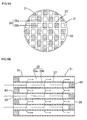
FIGS. 6A and 6B , used is aplugged honeycomb structure 31 including ahoneycomb structure 32 in which a plurality ofcells 39 in communication between two end faces are defined and formed by aporous partition wall 37, andplugged parts 40 disposed in checker board patterns that are complementary between one end face side and the other end face side of thehoneycomb structure 32 so that either one of two open ends of each of thecells 39 is plugged. - An exhaust gas flows in an internal part from one
end face 33 of a filter that is formed of suchplugged honeycomb structure 31, after having removed particulates and the like that are contained in the gas, and flows out from theother end face 35. In specific, first an exhaust gas flows in acell 39b which end portion is not plugged at oneend face 33 of this filter and which end portion is plugged at theother end face 35, penetrates aporous partition wall 37, moves to acell 39a which end portion is plugged at oneend face 33 and which end portion is not plugged at theother end face 35, and exhausted from thiscell 39a. Furthermore, on this occasion, thepartition wall 37 functions as a filter layer, and particulates in the gas are caught at thepartition wall 37 and accumulated on thepartition wall 37. - As a method of manufacturing the above-mentioned plugged honeycomb structure, known is a method in which after a transparent sheet and the like is adhered onto an end face of the honeycomb formed body and the end face is imaged, the position of each cell is recognized by image processing of the image having been shot, and based thereon, punching is made by e.g., laser machining in the position corresponding to the cell to be plugged of the sheet. Thereafter, an end portion of the honeycomb formed body is immersed in a plugging slurry that is slurry materials of a plugging part, and the plugging slurry is filled in the end portion of the cell that should be plugged, to form a plugged part (refer to, for example, Patent Document 1).
- In this manufacturing method, as mentioned above, recognition of the position of a cell is made by image recognition. In specific, an image of an end face of a honeycomb formed body having been imaged by e.g., a CCD (charge-coupled device) is binary-processed, and in the case in which a mass of black image in the images of having been binary-processed has a predetermined cell shape (for example, a quadrilateral shape), or reaches a predetermined rate (for example, not less than 80%) of a predetermined cell area, this image is determined to be a cell and the position thereof is recognized. Incidentally, an image that does not have a predetermined cell shape or that does not reach a certain rate of a predetermined cell area is determined to be a foreign substance such as dust that sticks to the end face of the honeycomb formed body, and punching is arranged not to be erroneously made in this position.
- However, since among cells, a cell that is positioned at the most outer peripheral portion of a honeycomb formed body (cell adjacent to the outer peripheral wall of the honeycomb formed body), as compared to the other cells, is shaped to be partially deformed, as well as has a smaller area, in the above-mentioned image processing, there are some cases in which its position is not recognized as a cell. Thus, even if the cell is the one that has to be plugged, no punching is made in the position corresponding to the cell of the sheet and a plugging slurry is not filled in the cell, so that as a result, a plugged part is not formed and a cell which both end portions are left to be open will remain.
- In such cells which both end portions remain to be open, since most particulates in an exhaust gas having flowed therein are not caught, but pass through the filter, the presence of the cell will cause the reduction of the performance as a filter.
- Incidentally, a honeycomb formed body to be supplied in manufacturing a plugged honeycomb structure by forming a plugged part is normally formed using a die for extrusion forming as illustrated in
FIG. 4 . This die 41 for extrusion forming includes: a honeycomb forming die 2 having the structure that there is provided at the surface a groove-like slit 4 in a form of acell block 5 and there is provided at the backside a clay introduction hole (back hole) 6 in communication with theslit 5; and a frame-shaped presser plate 3 that is disposed at the outer peripheral portion of the honeycomb forming die 2 and regulates the shape and dimension of the honeycomb formed body, and forming clay having been supplied from the backside is introduced into the honeycomb forming die 2 from theclay introduction hole 6 and extruded from the surface of thehoneycomb forming die 2 through theslit 4, to be a honeycomb formed body (refer to, for example, Patent Document 2). - As mentioned above, in comparison with the other cells, a cell that is positioned at the most outer peripheral portion having a partly deformed shape (hereinafter, in some cases, it may be referred to as "imperfect cell"), among cell blocks of the honeycomb forming die 2, in the extrusion direction of the forming clay, is formed by the clay having passed around a cell block 5' which
end face 5a' is positioned to be overlapped with an innercircumferential surface 3a of apresser plate 3. In theconventional die 41 for extrusion forming as illustrated inFIG. 4 , all thecell blocks 5 and 5' at least a part of whichend faces circumferential surface 3a of thepresser plate 3 have the same length, that is, it is general that the end faces 5a and 5a' of thesecell blocks 5 and 5' are present in the same plane. - [Patent Document 1] Japanese Patent Application Laid-Open No.
2001-300922 - [Patent Document 2] Japanese Patent Application Laid-Open No.
2003-285308 - The present invention has been made in view of the above-described problems of conventional techniques, and has an object of the present inbention is to provide a honeycomb formed body in which each cell has a predetermined shape and dimension, and there is present no cell having the shape and dimension that is different from a predetermined shape and dimension as mentioned above at the most outer peripheral portion.
- To achieve the above-mentioned object, according to the present invention, provided are the following die for extrusion forming, a method of forming a honeycomb formed body and a honeycomb formed body.
- [1] A die for extrusion forming (a first die for extrusion forming) for extrusion forming of a honeycomb formed body comprising a honeycomb forming die having a structure that there is provided at a surface a groove-like slit in a form of a cell block as well as there is provided at a backside a clay introduction hole in communication with the slit; and a frame-shaped presser plate that is disposed at an outer peripheral portion of the honeycomb forming die and that regulates a shape and dimension of a honeycomb formed body,
wherein among the cell blocks, in an extrusion direction of forming clay, a cell block whose end face is positioned to be overlapped with an inner circumferential surface of the presser plate is formed to be shorter than the other cell blocks resided inside the inner circumferential surface of the presser plate. - [2] The die for extrusion forming according to [1], wherein among the cell blocks, in an extrusion direction of forming clay, a cell block whose end face is positioned to be overlapped with an inner circumferential surface of the presser plate is formed to be not less than 1.0 mm shorter than the other cell blocks resided inside the inner circumferential surface of the presser plate.
- [3] A die for extrusion forming (a second die for extrusion forming) for extrusion forming of a honeycomb formed body comprising a honeycomb forming die having a structure that there is provided at a surface a groove-like slit in a form of a cell block as well as there is provided at a backside a clay introduction hole in communication with the slit, and a frame-shaped presser plate that is disposed at an outer peripheral portion of the honeycomb forming die and that regulates a shape and dimension of a honeycomb formed body, in which the cell blocks are in the state of being surrounded by an inner circumferential surface of the presser plate at the periphery, as well as in which an end face of a cell block positioned at the most outer peripheral portion differs from the inner circumferential surface of the presser plate by a distance corresponding to a thickness of an outer peripheral wall of the honeycomb formed body and is shaped to be along the inner circumferential surface of the presser plate,
wherein among the cell blocks positioned at the most outer peripheral portion, a cell block having an end face shape that is different from that of the other cell blocks resided inside the cell block is formed to be shorter than the other cell blocks resided inside the cell block. - [4] The die for extrusion forming according to [3], wherein among the cell blocks positioned at the most outer peripheral portion, a cell block having an end face shape that is different from that of the other cell blocks resided inside the cell block is formed to be not less than 1.0 mm shorter than the other cell blocks resided inside the cell block.
- [5] A method of forming a honeycomb formed body conducting an extrusion forming of a honeycomb formed body using a die for extrusion forming according to any one of [1] to [4].
- [6] A honeycomb formed body in which a plurality of cells in communication between two end faces are defined and formed by a partition wall,
wherein each cell has a predetermined shape and dimension, and there is present no cell having the shape and dimension that is different from the predetermined shape and dimension at the most outer peripheral portion. - [7] The honeycomb formed body according to [6] that is formed by a forming method according to [5].
- In case of forming a honeycomb formed body using a die for extrusion forming according to the present invention, it is possible to obtain a honeycomb formed body in which each cell has a predetermined shape and dimension and there is present no cell having the shape and dimension that is different from the predetermined shape and dimension at the most outer peripheral portion. In the honeycomb formed body having such structure, since there is present no imperfect cell that is hard to be recognized in image recognition, in the case of plugging of one end portion of each cell for the purpose of use in applications such as a diesel particulate filter (DPF), it is possible to recognize with accuracy the position of each cell by image processing and to form a plugged part almost surely at the end portion of the cell intended to be plugged.
-
-
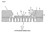
FIG. 1 is a schematically sectional view illustrating one example of an embodiment of a first die for extrusion forming according to the present invention. -
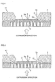
FIG. 2A is a schematically sectional view illustrating one example of an embodiment of a second die for extrusion forming according to the present invention. -
FIG. 2B is a schematically partial plan view illustrating one example of an embodiment of a second die for extrusion forming according to the present invention. -
FIG. 3 is a schematically sectional view illustrating one example of an embodiment of a forming method according to the present invention. -
FIG. 4 is a schematically sectional view illustrating one example of an embodiment of a conventional die for extrusion forming. -
FIG. 5 is a schematically sectional view illustrating one example of an embodiment of a conventional die for extrusion forming. -
FIG. 6A is a schematic plan view taken from one end face side illustrating a basic structure of a plugged honeycomb structure. -
FIG. 6B is a schematically sectional view illustrating a basic structure of a plugged honeycomb structure. -
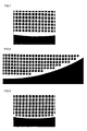
FIG. 7 is a partially enlarged photograph illustrating a principal portion of a honeycomb formed body obtained in Example 1. -
FIG. 8 is a partially enlarged photograph illustrating a principal portion of a honeycomb formed body obtained in Example 1. -
FIG. 9 is a partially enlarged photograph illustrating a principal portion of a honeycomb formed body obtained in Comparative Example. - 1: die for extrusion forming, 2; honeycomb forming die, 3: presser plate, 3a: inner circumferential surface, 4: slit, 5: cell block, 5': cell block, 5a: end face, 5a': end face, 6: clay introduction hole, 7: gap, 8: space, 9: spacer, 10: portion indicated by dotted lines, 11: die for extrusion forming, 12: honeycomb forming die, 13: presser plate, 13a: inner circumferential surface, 14: slit, 15: cell block, 15': cell block, 15a: end face, 15a': end face, 16: clay introduction hole, 18: space, 19: spacer, 21: extrusion passage, 31: plugged honeycomb structure, 32: honeycomb structure, 33: end face, 35: end face, 37: partition wall, 39: cell, 40: plugged part, 41: die for extrusion forming
- Hereinafter, typical preferred embodiments according to the present invention will be specifically described, but the present invention should not be limited to the following embodiments. It should be appreciated that modifications, improvements and the like of designs could be added as appropriate based on normal knowledge of persons skilled in the art without departing from the inventive concepts thereof.
-
FIG. 1 is a schematically sectional view illustrating one example of an embodiment of a first die for extrusion forming according to the present invention. A first die 1 for extrusion forming according to the present invention includes a honeycomb forming die 2 and apresser plate 3. The honeycomb forming die 2 has the structure that there is provided at the surface a groove-like slit 4 in a form of acell block 5, as well as there is provided at the backside a clay introduction hole (back hole) 6 in communication with theslit 4. Thepresser plate 3 is a frame-shaped member for regulating the shape and dimension of a honeycomb formed body, and disposed at the outer peripheral portion of the honeycomb forming die 2 via aspacer 9. - The
cell block 5 is a columnar part having the same sectional shape as that of a cell of a honeycomb formed body to be manufactured by extrusion forming, and a cell is defined and formed by a partition wall that is made of clay having passed through theslits 4 therearound to be extruded. As described above, in aconventional die 41 for extrusion forming as illustrated inFIG. 4 , all thecell blocks 5 and 5' at least a part of whoseend faces circumferential surface 3a of thepresser plate 3 have the same length, and all the end faces of thesecell blocks 5 and 5' are in the same plane. - Whereas, the first die for extrusion forming according to the present invention is characterized in its structure that of cell blocks of the
honeycomb forming die 2, in an extrusion direction of forming clay, the cell block 5' whoseend face 5a' is positioned to be overlapped with the innercircumferential surface 3a of thepresser plate 3 is formed to be shorter than theother cell blocks 5 that are resided inside the innercircumferential surface 3a of thepresser plate 3. That is, this cell block 5' is in the state in which its end face 5' is not in the same plane with theend face 5a of theother cell blocks 5, and viewed from the surface of thehoneycomb forming die 2, recessed in a direction opposite to the extrusion direction. More specifically, in thedie 41 for extrusion forming of a conventional structure illustrated inFIG. 5 , it is in the state in which a portion indicated bydotted lines 10 of a cell block whose end face is positioned to be overlapped with the innercircumferential surface 3a of thepresser plate 3 is removed, and by removal of theportion 10 indicated by dotted lines, in the first die 1 for extrusion forming according to the present invention, there is formed aspace 8 that is absent in the die for extrusion forming of the conventional structure as is illustrated inFIG. 1 . - In forming of a honeycomb formed body using such the first die 1 for extrusion forming, forming clay having been supplied from the backside of the
honeycomb forming die 2 is introduced into the honeycomb forming die 2 from theclay introduction hole 6, and extruded from the surface of thehoneycomb forming die 2 through theslits 4 to be a honeycomb formed body. Incidentally, the clay having been extruded from agap 7 between thehoneycomb forming die 2 and thepresser plate 3 mainly forms an outer peripheral wall of a honeycomb formed body. Here, in the case of using thedie 41 for extrusion forming of the conventional structure, with the clay having passed around the cell block 5' whose end face 5' is positioned to be overlapped with the innercircumferential surface 3a of thepresser plate 3, an imperfect cell will be formed; while in the case of using the first die 1 for extrusion forming according to the present invention, since the cell block 5' whoseend face 5a' is positioned to be overlapped with the innercircumferential surface 3a of thepresser plate 3 is formed to be shorter, whereby thespace 8 is formed at an extended portion of the cell block 5', the clay having passed around the cell block 5' flows in thespace 8 from the end portion of the cell block 5', and with the clay having flowed in thisspace 8, the cell which would have conventionally been an imperfect cell is extruded in the blocked state, as a result to be able to obtain a honeycomb formed body in which no imperfect cell is present. - In the first die for extrusion forming according to the present invention, it is preferred that among the cell blocks of the
honeycomb forming die 2, in the extrusion direction of forming clay, the cell block 5' whoseend face 5a' is positioned to be overlapped with the innercircumferential surface 3a of thepresser plate 3 is formed to be not less than 1. 0 mm shorter than theother cell blocks 5 resided inside the innercircumferential surface 3a of thepresser plate 3. In case where it is less than 1.0 mm, in some cases, the blockage of a cell may be done imperfectly. -
FIGS. 2A and 2B are schematic views illustrating one example of an embodiment of a second die for extrusion forming according to the present invention, andFIG. 2A is a sectional view andFIG. 2B is a partially plan view. Asecond die 11 for extrusion forming according to the present invention includes ahoneycomb forming die 12 and apresser plate 13. Thehoneycomb forming die 12 has the structure that there is provided at the surface a groove-like slit 14 in a form of acell block 15, as well as there is provided at the backside a clay introduction hole (back hole) 16 in communication with theslit 14. Thepresser plate 13 is a frame-shaped member for regulating the shape and dimension of a honeycomb formed body, and disposed at the outer peripheral portion of thehoneycomb forming die 12 via aspacer 19. The cell blocks are in the state of being surrounded by the innercircumferential surface 13a of thepresser plate 13 at the periphery, as well as the end face of the cell block that is positioned at the most outer peripheral portion differs from the innercircumferential surface 13a of thepresser plate 13 by a distance C corresponding to the thickness of the outer peripheral wall of the honeycomb formed body and has the shape along the innercircumferential surface 13a of thepresser plate 13. - Further, this second die 11 for extrusion forming is characterized in its structure that among the cell blocks positioned at the most outer periphery of the
honeycomb forming die 12, the cell block 15' having an end face shape which is different from that of theother cell blocks 15 that are resided inside the cell block is formed to be shorter than the other cell blocks resided inside the cell block. That is, this cell block 15' is in the state in which its end face 15' is not in the same plane with theend face 15a of theother cell blocks 15, and viewed from the surface of thehoneycomb forming die 12, recessed in a direction opposite to the extrusion direction, whereby aspace 18 is formed in an extended portion of the cell block 15'. - In forming of a honeycomb formed body using such the
second die 11 for extrusion forming, forming clay having been supplied from the backside of thehoneycomb forming die 12 is introduced into the honeycomb forming die 12 from theclay introduction hole 16, and extruded from the surface of thehoneycomb forming die 12 through theslits 14, to be a honeycomb formed body. Here, assuming that the cell block 15' has the same length as that of theother blocks 15, and nospace 18 is formed, with the clay having passed around the cell block 15', an imperfect cell will be formed; while in thesecond die 11 for extrusion forming according to the present invention, since the cell block 15' is formed to be shorter than theother cell blocks 15, whereby thespace 18 is formed in an extended portion of the cell block 15', the clay having passed around the cell block 15' flows in thespace 18 from the end portion of the cell block 15', and with the clay having flowed in thisspace 18, the cell which would have been an imperfect cell is extruded in the blocked state, as a result to be able to obtain a honeycomb formed body in which no imperfect cell is present. - In the
second die 11 for extrusion forming according to the present invention, it is preferred that among the cell blocks positioned at the most outer peripheral portion, the cell block 15' having an end face shape that is different from that of theother cell blocks 15 resided inside the cell block is formed to be not less than 1.0 mm shorter than theother cell blocks 15 resided inside the cell block. In case where it is less than 1.0 mm, in some cases, the blockage of a cell may be done imperfectly. - A method of forming a honeycomb formed body according to the present invention is to conduct extrusion forming of a honeycomb formed body using the first die for extrusion forming or the second die for extrusion forming according to the present invention. That is, as illustrated in
FIG. 3 , in anextrusion passage 21 of an extrusion forming apparatus, the first die 1 for extrusion forming according to the present invention (or thesecond die 11 for extrusion forming) is mounted, and forming clay is supplied in thepassage 21 and made to pass through the die 1 for extrusion forming (or thesecond die 11 for extrusion forming) according to the present invention, thereby conducting extrusion forming of a honeycomb formed body. In case of forming a honeycomb formed body by this forming method, it is possible to easily obtain a honeycomb formed body in which no imperfect cell is present. - The honeycomb formed body according to the present invention is a honeycomb formed body in which a plurality of cells to be in communication between two end faces are defined and formed by partition walls, and characterized in that each cell has a predetermined shape and dimension, and there is present at the most outer peripheral portion no cell having the shape and dimension different from the predetermined shape and dimension. That is, all the cells that are present in the honeycomb formed body according to the present invention have the same shape and dimension, and there is present no imperfect cell which recognition is hard to be done in image recognition. Therefore, in the case of plugging one end portion of each cell for the purpose of use in applications such as DPF, the position of each cell can be recognized with high accuracy by image processing, and a plugged part can be formed almost surely at the end portion of a cell intended to be plugged. It is possible to easily form such a honeycomb formed body by using the forming method according to the present invention.
- Hereinafter, although the present invention will be described in further detail based on examples, the present invention is not limited to these examples.
- As illustrated in
FIG. 1 , using the first die for extrusion forming which includes ahoneycomb forming die 2 having the structure that there is provided at the surface a groove-like slit 4 in a form of acell block 5 as well as there is provided at the backside aclay introduction hole 6 in communication with theslit 4; and a frame-shapedpresser plate 3 that is disposed at the outer peripheral portion of thishoneycomb forming die 2, and regulates the shape and dimension of the honeycomb formed body, and in which among the cell blocks, in an extrusion direction of forming clay, a cell block 5' whoseend face 5a' is positioned to be overlapped with an innercircumferential surface 3a of thepresser plate 3 is formed to be 1.0 mm shorter than theother cell blocks 5 resided inside the innercircumferential surface 3a of thepresser plate 3, extrusion forming of a honeycomb formed body was made. As forming clay, 100 parts by mass of raw material powder that contains talc, kaolin, alumina and silica was added with 5 parts by mass of methyl cellulose acting as a binder and 25 parts by mass of water, a mixture of substances was kneaded using a kneader, and the resulting material was used. In the honeycomb formed body having been obtained in such way, as illustrated in a partly enlarged photograph ofFIGS. 7 and 8 , each cell had a predetermined shape and dimension, and no imperfect cell was present at the most outer peripheral portion. - As illustrated in
FIGS. 2A and 2B , using the second die for extrusion forming according to the present invention which includes a honeycomb forming die 12 having the structure that there is provided at the surface a groove-like slit 14 in a form of a cell block 15 as well as there is provided at the backside a clay introduction hole 16 in communication with the slit 14; and a frame-shaped presser plate 13 that is disposed at the outer periphery of this honeycomb forming die 12, and regulates the shape and dimension of the honeycomb formed body, in which the cell blocks are in the state of being surrounded by an inner circumferential surface 13a of the presser plate 13 at the periphery, as well as the end face of the cell block positioned at the most outer peripheral portion differs from the inner circumferential surface 13a of the presser plate 13 by a distance C corresponding to the thickness of the outer peripheral wall of the honeycomb formed body and is shaped to be along the inner circumferential surface 13a of the presser plate 13, and in which among the cell blocks positioned at the most outer periphery, a cell block 15' having an end face shape that is different from that of the other cell blocks 15 resided inside the cell block is formed to be 1.0 mm shorter than the other cell blocks 15 resided inside the cell block, extrusion forming of a honeycomb formed body was made. The forming clay employed was the same one as that of the Example 1. In the honeycomb formed body having been obtained in such way, as is the honeycomb formed body obtained in Example 1, each cell had a predetermined shape and dimension, and no imperfect cell was present at the most outer peripheral portion. - As illustrated in
FIG. 4 , using a die for extrusion forming of a conventional structure which includes ahoneycomb forming die 2 having the structure that there is provided at the surface a groove-like slit 4 in a form of acell block 5 as well as there is provided at the backside aclay introduction hole 6 in communication with theslit 4 and a frame-shapedpresser plate 3 that is disposed at the outer peripheral portion of thishoneycomb forming die 2, and regulates the shape and dimension of the honeycomb formed body, and in which allcell blocks 5 and 5' at least a part of whose end faces 5a and 5a' is resided inside an innercircumferential surface 3a of thepresser plate 3 have the same length, extrusion forming of a honeycomb formed body was made. The forming clay employed was the same one as that of the Example 1. In the honeycomb formed body having been obtained in such way, as is illustrated in a partly enlarged photograph ofFIG. 9 , an imperfect cell was formed at the most outer peripheral portion. - The present invention can be preferably utilized in forming a honeycomb formed body to be used by plugging one end portion of cells, for the purpose of use in application such as DPF.
Claims (7)
- A die for extrusion forming for extrusion forming of a honeycomb formed body comprising a honeycomb forming die having a structure that there is provided at a surface a groove-like slit in a form of a cell block as well as there is provided at a backside a clay introduction hole in communication with said slit; and a frame-shaped presser plate that is disposed at an outer peripheral portion of the honeycomb forming die and that regulates a shape and dimension of a honeycomb formed body,
wherein among said cell blocks, in an extrusion direction of forming clay, a cell block whose end face is positioned to be overlapped with an inner circumferential surface of said presser plate is formed to be shorter than the other cell blocks resided inside the inner circumferential surface of said presser plate. - The die for extrusion forming according to claim 1, wherein among the cell blocks, in an extrusion direction of forming clay, a cell block whose end face is positioned to be overlapped with an inner circumferential surface of the presser plate is formed to be not less than 1.0 mm shorter than the other cell blocks resided inside the inner circumferential surface of said presser plate.
- A die for extrusion forming for extrusion forming of a honeycomb formed body comprising a honeycomb forming die having a structure that there is provided at a surface a groove-like slit in a form of a cell block as well as there is provided at a backside a clay introduction hole in communication with said slit, and a frame-shaped presser plate that is disposed at an outer peripheral portion of the honeycomb forming die and that regulates a shape and dimension of a honeycomb formed body, in which the cell blocks are in the state of being surrounded by an inner circumferential surface of the presser plate at the periphery, as well as in which an end face of a cell block positioned at the most outer peripheral portion differs from the inner circumferential surface of said presser plate by a distance corresponding to a thickness of an outer peripheral wall of the honeycomb formed body and is shaped to be along the inner circumferential surface of the presser plate,
wherein among the cell blocks positioned at said most outer peripheral portion, a cell block having an end face shape that is different from that of the other cell blocks resided inside the cell block is formed to be shorter than the other cell blocks resided inside the cell block. - The die for extrusion forming according to claim 3, wherein among the cell blocks positioned at the most outer peripheral portion, a cell block having an end face shape that is different from that of the other cell blocks resided inside the cell block is formed to be not less than 1.0 mm shorter than the other cell blocks resided inside the cell block.
- A method of forming a honeycomb formed body conducting an extrusion forming of a honeycomb formed body using a die for extrusion forming according to any one of claims 1 to 4.
- A honeycomb formed body in which a plurality of cells in communication between two end faces are defined and formed by a partition wall,
wherein each cell has a predetermined shape and dimension, and there is present no cell having the shape and dimension that is different from the predetermined shape and dimension at the most outer peripheral portion. - The honeycomb formed body according to claim 6 that is formed by a forming method according to claim 5.
Applications Claiming Priority (2)
| Application Number | Priority Date | Filing Date | Title |
|---|---|---|---|
| JP2007023566 | 2007-02-01 | ||
| PCT/JP2008/051466 WO2008093760A1 (en) | 2007-02-01 | 2008-01-24 | Die for extrusion forming of honeycomb formed body, method of forming honeycomb formed body, and honeycomb formed body |
Publications (3)
| Publication Number | Publication Date |
|---|---|
| EP2127836A1 true EP2127836A1 (en) | 2009-12-02 |
| EP2127836A4 EP2127836A4 (en) | 2012-07-04 |
| EP2127836B1 EP2127836B1 (en) | 2013-12-11 |
Family
ID=39674067
Family Applications (1)
| Application Number | Title | Priority Date | Filing Date |
|---|---|---|---|
| EP08704219.8A Active EP2127836B1 (en) | 2007-02-01 | 2008-01-24 | Dies for extrusion forming of honeycomb formed body and method of forming honeycomb formed body using said dies |
Country Status (4)
| Country | Link |
|---|---|
| US (1) | US8851877B2 (en) |
| EP (1) | EP2127836B1 (en) |
| JP (1) | JP5528709B2 (en) |
| WO (1) | WO2008093760A1 (en) |
Cited By (1)
| Publication number | Priority date | Publication date | Assignee | Title |
|---|---|---|---|---|
| CN107877674A (en) * | 2017-11-14 | 2018-04-06 | 南昌航空大学 | A kind of method for strengthening three-way catalytic converter carrier extrusion die |
Families Citing this family (2)
| Publication number | Priority date | Publication date | Assignee | Title |
|---|---|---|---|---|
| EP2857164B1 (en) * | 2012-06-04 | 2019-03-20 | NGK Insulators, Ltd. | Spinneret for molding honeycomb structure and manufacturing method therefor |
| EP3569311A1 (en) * | 2018-05-18 | 2019-11-20 | Basf Se | Matrix with metal printed parts for the extrusion of shaped bodies |
Family Cites Families (12)
| Publication number | Priority date | Publication date | Assignee | Title |
|---|---|---|---|---|
| JPS5777521A (en) | 1980-10-31 | 1982-05-14 | Nippon Soken | Die device for molding honeycomb structure |
| JPS57157706A (en) * | 1981-03-25 | 1982-09-29 | Nippon Soken | Die for molding honeycomb |
| JPS63299902A (en) * | 1987-05-30 | 1988-12-07 | Ngk Insulators Ltd | Mold for extrusion molding and extrusion molding of ceramic honeycomb structural body by using it |
| JP3768550B2 (en) * | 1994-03-11 | 2006-04-19 | 日本碍子株式会社 | Ceramic honeycomb structure |
| JP3701801B2 (en) * | 1998-10-29 | 2005-10-05 | 日本碍子株式会社 | Die for honeycomb manufacturing |
| JP3701802B2 (en) * | 1998-10-29 | 2005-10-05 | 日本碍子株式会社 | Die for honeycomb manufacturing |
| JP3715174B2 (en) | 2000-04-18 | 2005-11-09 | 日本碍子株式会社 | Manufacturing method of ceramic body |
| JP2002283327A (en) * | 2001-03-28 | 2002-10-03 | Ngk Insulators Ltd | Honeycomb structure forming apparatus and forming method |
| JP2003285308A (en) | 2002-03-28 | 2003-10-07 | Ngk Insulators Ltd | Honeycomb-forming die and honeycomb-forming die using the same |
| JP2005007218A (en) * | 2003-06-16 | 2005-01-13 | Hitachi Metals Ltd | Ceramic honeycomb structure body and metal mold for ceramic honeycomb structure body |
| JP4528185B2 (en) * | 2005-03-31 | 2010-08-18 | 日本碍子株式会社 | Honeycomb structure extrusion molding equipment |
| US7914724B2 (en) * | 2005-07-29 | 2011-03-29 | Corning Incorporated | Methods for extruding a honeycomb article with a skin surrrounding a central cellular structure |
-
2008
- 2008-01-24 EP EP08704219.8A patent/EP2127836B1/en active Active
- 2008-01-24 WO PCT/JP2008/051466 patent/WO2008093760A1/en not_active Ceased
- 2008-01-24 JP JP2008556161A patent/JP5528709B2/en active Active
-
2009
- 2009-07-28 US US12/510,743 patent/US8851877B2/en active Active
Cited By (1)
| Publication number | Priority date | Publication date | Assignee | Title |
|---|---|---|---|---|
| CN107877674A (en) * | 2017-11-14 | 2018-04-06 | 南昌航空大学 | A kind of method for strengthening three-way catalytic converter carrier extrusion die |
Also Published As
| Publication number | Publication date |
|---|---|
| US8851877B2 (en) | 2014-10-07 |
| EP2127836B1 (en) | 2013-12-11 |
| US20090311470A1 (en) | 2009-12-17 |
| EP2127836A4 (en) | 2012-07-04 |
| JP5528709B2 (en) | 2014-06-25 |
| JPWO2008093760A1 (en) | 2010-05-20 |
| WO2008093760A1 (en) | 2008-08-07 |
Similar Documents
| Publication | Publication Date | Title |
|---|---|---|
| EP1470852B1 (en) | Honeycomb structure and method of manufacturing the same | |
| EP2918566B1 (en) | Plugged honeycomb structure and manufacturing method of the same | |
| KR101610573B1 (en) | Honeycomb structure | |
| CN107199053B (en) | Honeycomb structure | |
| JP5150511B2 (en) | Method for manufacturing plugged honeycomb structure | |
| KR101114804B1 (en) | Holding seal member for exhaust gas treating element and exhaust gas treating device | |
| JP5632318B2 (en) | Honeycomb filter and manufacturing method thereof | |
| US20080047638A1 (en) | Holding sealer and exhaust gas processing device | |
| DE102017002266A1 (en) | honeycomb structure | |
| US8851877B2 (en) | Die for extrusion forming of honeycomb formed body, and method of forming honeycomb formed body | |
| CN109833693B (en) | Honeycomb filter | |
| US10947877B2 (en) | Exhaust gas purification filter | |
| JP2008045521A (en) | Holding sealing material and exhaust gas treatment device | |
| JP5171279B2 (en) | Honeycomb structure, filter and exhaust gas treatment device | |
| WO2013099814A1 (en) | Extrusion-molding die | |
| DE112019005955T5 (en) | Honeycomb structure, emission control device and exhaust system | |
| JP3945452B2 (en) | Manufacturing method of exhaust gas purification filter | |
| DE102018205711B4 (en) | HONEYCOMB FILTER | |
| US20190351577A1 (en) | Ceramic formed body extrusion method, ceramic formed body, and ceramic porous body | |
| US20060105140A1 (en) | Mask for plugging particulate filter cells | |
| EP2835166A1 (en) | Honeycomb structure | |
| KR100631774B1 (en) | Method of manufacturing the composite material | |
| CN119731422B (en) | Gasket and holding sealing material | |
| US20250303334A1 (en) | Honeycomb filter | |
| US8745856B2 (en) | Method for producing a ceramic filter element |
Legal Events
| Date | Code | Title | Description |
|---|---|---|---|
| PUAI | Public reference made under article 153(3) epc to a published international application that has entered the european phase |
Free format text: ORIGINAL CODE: 0009012 |
|
| 17P | Request for examination filed |
Effective date: 20090820 |
|
| AK | Designated contracting states |
Kind code of ref document: A1 Designated state(s): AT BE BG CH CY CZ DE DK EE ES FI FR GB GR HR HU IE IS IT LI LT LU LV MC MT NL NO PL PT RO SE SI SK TR |
|
| DAX | Request for extension of the european patent (deleted) | ||
| RIC1 | Information provided on ipc code assigned before grant |
Ipc: B28B 3/26 20060101AFI20120328BHEP Ipc: B01D 39/00 20060101ALI20120328BHEP Ipc: B01D 46/00 20060101ALI20120328BHEP Ipc: B01D 39/20 20060101ALI20120328BHEP |
|
| A4 | Supplementary search report drawn up and despatched |
Effective date: 20120606 |
|
| RIC1 | Information provided on ipc code assigned before grant |
Ipc: B29L 31/60 20060101ALI20120531BHEP Ipc: B28B 3/26 20060101ALI20120531BHEP Ipc: B01D 46/24 20060101AFI20120531BHEP |
|
| REG | Reference to a national code |
Ref country code: DE Ref legal event code: R079 Ref document number: 602008029225 Country of ref document: DE Free format text: PREVIOUS MAIN CLASS: B28B0003260000 Ipc: B01D0046240000 |
|
| RIC1 | Information provided on ipc code assigned before grant |
Ipc: B29L 31/60 20060101ALI20130515BHEP Ipc: B29C 47/20 20060101ALI20130515BHEP Ipc: B29C 47/12 20060101ALI20130515BHEP Ipc: B01D 46/24 20060101AFI20130515BHEP Ipc: B29C 47/00 20060101ALI20130515BHEP Ipc: B28B 3/26 20060101ALI20130515BHEP |
|
| GRAP | Despatch of communication of intention to grant a patent |
Free format text: ORIGINAL CODE: EPIDOSNIGR1 |
|
| INTG | Intention to grant announced |
Effective date: 20130626 |
|
| GRAS | Grant fee paid |
Free format text: ORIGINAL CODE: EPIDOSNIGR3 |
|
| GRAA | (expected) grant |
Free format text: ORIGINAL CODE: 0009210 |
|
| AK | Designated contracting states |
Kind code of ref document: B1 Designated state(s): AT BE BG CH CY CZ DE DK EE ES FI FR GB GR HR HU IE IS IT LI LT LU LV MC MT NL NO PL PT RO SE SI SK TR |
|
| REG | Reference to a national code |
Ref country code: GB Ref legal event code: FG4D |
|
| REG | Reference to a national code |
Ref country code: CH Ref legal event code: EP |
|
| REG | Reference to a national code |
Ref country code: AT Ref legal event code: REF Ref document number: 644170 Country of ref document: AT Kind code of ref document: T Effective date: 20140115 |
|
| REG | Reference to a national code |
Ref country code: IE Ref legal event code: FG4D |
|
| REG | Reference to a national code |
Ref country code: DE Ref legal event code: R096 Ref document number: 602008029225 Country of ref document: DE Effective date: 20140206 |
|
| REG | Reference to a national code |
Ref country code: NL Ref legal event code: VDEP Effective date: 20131211 |
|
| REG | Reference to a national code |
Ref country code: AT Ref legal event code: MK05 Ref document number: 644170 Country of ref document: AT Kind code of ref document: T Effective date: 20131211 |
|
| PG25 | Lapsed in a contracting state [announced via postgrant information from national office to epo] |
Ref country code: LT Free format text: LAPSE BECAUSE OF FAILURE TO SUBMIT A TRANSLATION OF THE DESCRIPTION OR TO PAY THE FEE WITHIN THE PRESCRIBED TIME-LIMIT Effective date: 20131211 Ref country code: SE Free format text: LAPSE BECAUSE OF FAILURE TO SUBMIT A TRANSLATION OF THE DESCRIPTION OR TO PAY THE FEE WITHIN THE PRESCRIBED TIME-LIMIT Effective date: 20131211 Ref country code: HR Free format text: LAPSE BECAUSE OF FAILURE TO SUBMIT A TRANSLATION OF THE DESCRIPTION OR TO PAY THE FEE WITHIN THE PRESCRIBED TIME-LIMIT Effective date: 20131211 Ref country code: NL Free format text: LAPSE BECAUSE OF FAILURE TO SUBMIT A TRANSLATION OF THE DESCRIPTION OR TO PAY THE FEE WITHIN THE PRESCRIBED TIME-LIMIT Effective date: 20131211 Ref country code: NO Free format text: LAPSE BECAUSE OF FAILURE TO SUBMIT A TRANSLATION OF THE DESCRIPTION OR TO PAY THE FEE WITHIN THE PRESCRIBED TIME-LIMIT Effective date: 20140311 Ref country code: FI Free format text: LAPSE BECAUSE OF FAILURE TO SUBMIT A TRANSLATION OF THE DESCRIPTION OR TO PAY THE FEE WITHIN THE PRESCRIBED TIME-LIMIT Effective date: 20131211 |
|
| REG | Reference to a national code |
Ref country code: LT Ref legal event code: MG4D |
|
| PG25 | Lapsed in a contracting state [announced via postgrant information from national office to epo] |
Ref country code: AT Free format text: LAPSE BECAUSE OF FAILURE TO SUBMIT A TRANSLATION OF THE DESCRIPTION OR TO PAY THE FEE WITHIN THE PRESCRIBED TIME-LIMIT Effective date: 20131211 Ref country code: LV Free format text: LAPSE BECAUSE OF FAILURE TO SUBMIT A TRANSLATION OF THE DESCRIPTION OR TO PAY THE FEE WITHIN THE PRESCRIBED TIME-LIMIT Effective date: 20131211 Ref country code: CY Free format text: LAPSE BECAUSE OF FAILURE TO SUBMIT A TRANSLATION OF THE DESCRIPTION OR TO PAY THE FEE WITHIN THE PRESCRIBED TIME-LIMIT Effective date: 20131211 |
|
| PG25 | Lapsed in a contracting state [announced via postgrant information from national office to epo] |
Ref country code: IS Free format text: LAPSE BECAUSE OF FAILURE TO SUBMIT A TRANSLATION OF THE DESCRIPTION OR TO PAY THE FEE WITHIN THE PRESCRIBED TIME-LIMIT Effective date: 20140411 Ref country code: BE Free format text: LAPSE BECAUSE OF FAILURE TO SUBMIT A TRANSLATION OF THE DESCRIPTION OR TO PAY THE FEE WITHIN THE PRESCRIBED TIME-LIMIT Effective date: 20131211 Ref country code: EE Free format text: LAPSE BECAUSE OF FAILURE TO SUBMIT A TRANSLATION OF THE DESCRIPTION OR TO PAY THE FEE WITHIN THE PRESCRIBED TIME-LIMIT Effective date: 20131211 |
|
| PG25 | Lapsed in a contracting state [announced via postgrant information from national office to epo] |
Ref country code: ES Free format text: LAPSE BECAUSE OF FAILURE TO SUBMIT A TRANSLATION OF THE DESCRIPTION OR TO PAY THE FEE WITHIN THE PRESCRIBED TIME-LIMIT Effective date: 20131211 Ref country code: RO Free format text: LAPSE BECAUSE OF FAILURE TO SUBMIT A TRANSLATION OF THE DESCRIPTION OR TO PAY THE FEE WITHIN THE PRESCRIBED TIME-LIMIT Effective date: 20131211 Ref country code: SK Free format text: LAPSE BECAUSE OF FAILURE TO SUBMIT A TRANSLATION OF THE DESCRIPTION OR TO PAY THE FEE WITHIN THE PRESCRIBED TIME-LIMIT Effective date: 20131211 Ref country code: PT Free format text: LAPSE BECAUSE OF FAILURE TO SUBMIT A TRANSLATION OF THE DESCRIPTION OR TO PAY THE FEE WITHIN THE PRESCRIBED TIME-LIMIT Effective date: 20140411 Ref country code: CZ Free format text: LAPSE BECAUSE OF FAILURE TO SUBMIT A TRANSLATION OF THE DESCRIPTION OR TO PAY THE FEE WITHIN THE PRESCRIBED TIME-LIMIT Effective date: 20131211 Ref country code: LU Free format text: LAPSE BECAUSE OF FAILURE TO SUBMIT A TRANSLATION OF THE DESCRIPTION OR TO PAY THE FEE WITHIN THE PRESCRIBED TIME-LIMIT Effective date: 20140124 Ref country code: PL Free format text: LAPSE BECAUSE OF FAILURE TO SUBMIT A TRANSLATION OF THE DESCRIPTION OR TO PAY THE FEE WITHIN THE PRESCRIBED TIME-LIMIT Effective date: 20131211 |
|
| REG | Reference to a national code |
Ref country code: CH Ref legal event code: PL |
|
| REG | Reference to a national code |
Ref country code: DE Ref legal event code: R097 Ref document number: 602008029225 Country of ref document: DE |
|
| PG25 | Lapsed in a contracting state [announced via postgrant information from national office to epo] |
Ref country code: MC Free format text: LAPSE BECAUSE OF FAILURE TO SUBMIT A TRANSLATION OF THE DESCRIPTION OR TO PAY THE FEE WITHIN THE PRESCRIBED TIME-LIMIT Effective date: 20131211 |
|
| PLBE | No opposition filed within time limit |
Free format text: ORIGINAL CODE: 0009261 |
|
| STAA | Information on the status of an ep patent application or granted ep patent |
Free format text: STATUS: NO OPPOSITION FILED WITHIN TIME LIMIT |
|
| PG25 | Lapsed in a contracting state [announced via postgrant information from national office to epo] |
Ref country code: DK Free format text: LAPSE BECAUSE OF FAILURE TO SUBMIT A TRANSLATION OF THE DESCRIPTION OR TO PAY THE FEE WITHIN THE PRESCRIBED TIME-LIMIT Effective date: 20131211 Ref country code: CH Free format text: LAPSE BECAUSE OF NON-PAYMENT OF DUE FEES Effective date: 20140131 Ref country code: LI Free format text: LAPSE BECAUSE OF NON-PAYMENT OF DUE FEES Effective date: 20140131 |
|
| REG | Reference to a national code |
Ref country code: IE Ref legal event code: MM4A |
|
| 26N | No opposition filed |
Effective date: 20140912 |
|
| GBPC | Gb: european patent ceased through non-payment of renewal fee |
Effective date: 20140311 |
|
| REG | Reference to a national code |
Ref country code: DE Ref legal event code: R097 Ref document number: 602008029225 Country of ref document: DE Effective date: 20140912 |
|
| PG25 | Lapsed in a contracting state [announced via postgrant information from national office to epo] |
Ref country code: GB Free format text: LAPSE BECAUSE OF NON-PAYMENT OF DUE FEES Effective date: 20140311 Ref country code: IE Free format text: LAPSE BECAUSE OF NON-PAYMENT OF DUE FEES Effective date: 20140124 |
|
| PG25 | Lapsed in a contracting state [announced via postgrant information from national office to epo] |
Ref country code: SI Free format text: LAPSE BECAUSE OF FAILURE TO SUBMIT A TRANSLATION OF THE DESCRIPTION OR TO PAY THE FEE WITHIN THE PRESCRIBED TIME-LIMIT Effective date: 20131211 |
|
| REG | Reference to a national code |
Ref country code: FR Ref legal event code: PLFP Year of fee payment: 9 |
|
| PG25 | Lapsed in a contracting state [announced via postgrant information from national office to epo] |
Ref country code: MT Free format text: LAPSE BECAUSE OF FAILURE TO SUBMIT A TRANSLATION OF THE DESCRIPTION OR TO PAY THE FEE WITHIN THE PRESCRIBED TIME-LIMIT Effective date: 20131211 |
|
| PG25 | Lapsed in a contracting state [announced via postgrant information from national office to epo] |
Ref country code: BG Free format text: LAPSE BECAUSE OF FAILURE TO SUBMIT A TRANSLATION OF THE DESCRIPTION OR TO PAY THE FEE WITHIN THE PRESCRIBED TIME-LIMIT Effective date: 20131211 |
|
| PG25 | Lapsed in a contracting state [announced via postgrant information from national office to epo] |
Ref country code: GR Free format text: LAPSE BECAUSE OF FAILURE TO SUBMIT A TRANSLATION OF THE DESCRIPTION OR TO PAY THE FEE WITHIN THE PRESCRIBED TIME-LIMIT Effective date: 20140312 Ref country code: IT Free format text: LAPSE BECAUSE OF FAILURE TO SUBMIT A TRANSLATION OF THE DESCRIPTION OR TO PAY THE FEE WITHIN THE PRESCRIBED TIME-LIMIT Effective date: 20131211 |
|
| PG25 | Lapsed in a contracting state [announced via postgrant information from national office to epo] |
Ref country code: TR Free format text: LAPSE BECAUSE OF FAILURE TO SUBMIT A TRANSLATION OF THE DESCRIPTION OR TO PAY THE FEE WITHIN THE PRESCRIBED TIME-LIMIT Effective date: 20131211 Ref country code: HU Free format text: LAPSE BECAUSE OF FAILURE TO SUBMIT A TRANSLATION OF THE DESCRIPTION OR TO PAY THE FEE WITHIN THE PRESCRIBED TIME-LIMIT; INVALID AB INITIO Effective date: 20080124 |
|
| REG | Reference to a national code |
Ref country code: FR Ref legal event code: PLFP Year of fee payment: 10 |
|
| REG | Reference to a national code |
Ref country code: FR Ref legal event code: PLFP Year of fee payment: 11 |
|
| PGFP | Annual fee paid to national office [announced via postgrant information from national office to epo] |
Ref country code: FR Payment date: 20191216 Year of fee payment: 13 |
|
| PG25 | Lapsed in a contracting state [announced via postgrant information from national office to epo] |
Ref country code: FR Free format text: LAPSE BECAUSE OF NON-PAYMENT OF DUE FEES Effective date: 20210131 |
|
| PGFP | Annual fee paid to national office [announced via postgrant information from national office to epo] |
Ref country code: DE Payment date: 20251203 Year of fee payment: 19 |