EP2127794A1 - Locking device for rotary cutting tool - Google Patents
Locking device for rotary cutting tool Download PDFInfo
- Publication number
- EP2127794A1 EP2127794A1 EP08722594A EP08722594A EP2127794A1 EP 2127794 A1 EP2127794 A1 EP 2127794A1 EP 08722594 A EP08722594 A EP 08722594A EP 08722594 A EP08722594 A EP 08722594A EP 2127794 A1 EP2127794 A1 EP 2127794A1
- Authority
- EP
- European Patent Office
- Prior art keywords
- operating lever
- screw
- flange
- fixing device
- lever
- Prior art date
- Legal status (The legal status is an assumption and is not a legal conclusion. Google has not performed a legal analysis and makes no representation as to the accuracy of the status listed.)
- Withdrawn
Links
- 238000005520 cutting process Methods 0.000 title abstract description 29
- 230000005484 gravity Effects 0.000 claims description 6
- 230000002093 peripheral effect Effects 0.000 claims description 4
- 238000009826 distribution Methods 0.000 claims description 3
- 241000763859 Dyckia brevifolia Species 0.000 abstract 1
- 229910000831 Steel Inorganic materials 0.000 description 8
- 239000010959 steel Substances 0.000 description 8
- 238000005096 rolling process Methods 0.000 description 7
- 229910052751 metal Inorganic materials 0.000 description 6
- 239000002184 metal Substances 0.000 description 6
- 238000000034 method Methods 0.000 description 5
- 238000010276 construction Methods 0.000 description 4
- 239000000463 material Substances 0.000 description 4
- 238000003825 pressing Methods 0.000 description 3
- 230000000717 retained effect Effects 0.000 description 3
- 238000003860 storage Methods 0.000 description 3
- 230000004048 modification Effects 0.000 description 2
- 238000012986 modification Methods 0.000 description 2
- 239000011248 coating agent Substances 0.000 description 1
- 238000000576 coating method Methods 0.000 description 1
- 230000007423 decrease Effects 0.000 description 1
- 229910001385 heavy metal Inorganic materials 0.000 description 1
- 230000002265 prevention Effects 0.000 description 1
- 239000011347 resin Substances 0.000 description 1
- 229920005989 resin Polymers 0.000 description 1
- 230000000630 rising effect Effects 0.000 description 1
Images




Classifications
-
- B—PERFORMING OPERATIONS; TRANSPORTING
- B27—WORKING OR PRESERVING WOOD OR SIMILAR MATERIAL; NAILING OR STAPLING MACHINES IN GENERAL
- B27B—SAWS FOR WOOD OR SIMILAR MATERIAL; COMPONENTS OR ACCESSORIES THEREFOR
- B27B5/00—Sawing machines working with circular or cylindrical saw blades; Components or equipment therefor
- B27B5/29—Details; Component parts; Accessories
- B27B5/30—Details; Component parts; Accessories for mounting or securing saw blades or saw spindles
- B27B5/32—Devices for securing circular saw blades to the saw spindle
Definitions
- the present invention relates to a fixing device (tool-less blade clamp) for fixing a rotary blade such as a saw blade to a spindle without the use of a special tool in a rotary tool such as, for example, a portable circular saw.
- Patent Document 1 a tool-less blade clamp assembly (fixing screw) which can be manually loosened without using a tool by utilizing a ratchet mechanism in order to prevent over-tightening is described in the following Patent Document 1.
- a retractable lever is provided in a fixing nut tightened to a threaded shaft part of a spindle, and the fixing nut can be tightened to the threaded shaft part of the spindle with a large torque while this lever is grasped, thereby enabling a user to firmly fix a rotary blade to the spindle without using a special tool such as a spanner, etc.
- the lever is retracted not to extend from the fixing nut so as not to interfere with the rotational movement of the rotary blade. Further, also in the case that the fixing nut is loosened, it is possible to pull out this lever and rotate the fixing unit in the loosening direction with a large torque, so that a user can manually loosen the fixing nut and remove the rotary blade without using a special tool.
- Patent Document 1 a fixing screw described in the former Patent Document 1 is characterized in that it can be manually operated by a user, the document does not disclose a technique for tightening it firmly.
- Patent Document 2 provides a fixing nut for fixing a saw blade to a spindle of a cutting machine body. Though this fixing nut can be tightened and loosened with a large torque, this Patent Document 2 does not disclose a technique for its compactification with respect to a radial direction or a thickness direction.
- the present invention provides fixing devices constructed as described in the claims, respectively.
- the operating lever is provided without increase in size of the screw body with respect to its radial direction and thickness direction, and therefore, when it is applied to an existing portable circular saw, a sufficient cutting depth of the saw blade can be ensured while an inclination angle of the portable circular saw body is maintained when an oblique cutting operation is performed.
- a function as a tool-less clamp (a fixing device which needs no tool) can be given.
- a large rotational force can be applied to the screw body by taking out an operating lever of the fixing device to its use position and applying a torque to the screw body via this lever, and therefore, the screw body can be tightened firmly without the use of a special tool.
- the screw flange has a truncated cone shape and the operating lever is received without protruding from the peripheral edge of the screw flange.
- the rotary tool is a portable circular saw including a main body having a saw blade, and a base which tiltably supports this main body, a protruding distance of the saw blade toward a lower surface side of the base, that is a cutting depth, can be ensured to be sufficient while the main body is inclined with respect to the base to incline the saw blade at a predetermined angle within a range that does not cause interference of the fixing device with the base.
- a tool-less function can be added without sacrificing a cutting depth when an oblique cutting operation is performed.
- the screw flange With regard to an outer configuration of the screw flange, it does not need to have an exactly (accurately) truncated cone shape.
- the key is that the screw flange needs to be tapered so that its leading portion side becomes thin, enabling prevention of interference between the fixing device and the other parts when the rotary tool is inclined, and enabling setting of an inclination angle of the rotary tool to be large.
- the operating lever is received within the lever receiving concave part in the state where it does not protrude from the peripheral edge of the screw flange when viewed not only from the front side but also from the lateral side.
- the fixing device can be configured to be compact in its thickness direction and radial direction, so that an inclination angle of the rotary tool body can be set to be large.
- a user can take the operating lever out of the lever receiving concave part to its use position against the biasing force, and when the user releases the operating lever which is taken out to its use position, it returns to the received position automatically. In this respect, the usability of the fixing device can be improved.
- a rotational torque (rotational operating force) applied in the tightened direction or loosening direction to the screw body via the operating lever can be efficiently applied to a screw shaft portion. More specifically, a rotational torque applied to the screw body by a user is not consumed as a friction resistance (rotational resistance) between the screw flange and the outer flange, but substantially the entire torque is applied to the screw shaft portion. In this respect, a necessary rotational torque to tighten or loosen the screw shaft portion can be reduced, so that a necessary rotational operating force can be further reduced.
- the outer flange and the inner flange are integrated with respect to the rotation, for example, by fitting them with a two surface width portion of the spindle.
- the rotary blade can be reliably and easily mounted coaxially to the spindle via the inner flange.
- an operating force in the taking out direction and a retaining force in its taking-out position applied to the operating lever by a user can be received dispersedly at two points of the support shaft and the receiving base.
- FIG. shows a portable circular saw 1 with a circular saw blade 2 fixed by using a fixing device 10 of this embodiment.
- the present embodiment exemplifies the portable circular saw 1 as an example of rotary tools, and the circular saw blade 2 as an example of rotary blades.
- the constitution of the portable circular saw 1 itself is similar to that known in the prior art and requires no particular modification in the present embodiment.
- the periphery of an upper half circumference of the saw blade 2 is covered with a blade case 3.
- a driving motor and a speed-reducing mechanism is located at the backside of this blade case 3. An output of this driving motor is transmitted via the speed-reducing mechanism into a spindle 5 protruding into the blade case.
- Symbol 4 in FIG.1 designates a base adapted to contact with a cut material W.
- the blade case 3 is supported on the upper surface of this base 4, and the lower side of the saw blade 2 protrudes on a lower surface side of this base 4.
- the cut material is cut by this protruding portion.
- the blade case 3 is supported by the base so as to be capable of tilting upward and downward, so that a protruding distance of the saw blade can be changed for adjusting a cutting depth for the cut material. Further, the blade case 3 is supported on the base 4 so as to be capable of tilting in right and left directions with respect to a cutting direction (a direction intersecting the sheet face).
- This fixing device 10 is provided with an outer flange 11 and an inner flange 12 which clamp the saw blade 2, and a screw body 20. Both the outer flange 11 and the inner flange 12 are mounted to two surface width portions 5b, 5b formed at a leading end of the spindle 5 so as to be non-rotatable relative to the spindle 5.
- the outer flange 11 is brought to contact with an outer side (left side surface in FIGS.3 and 5 ) of the saw blade 2, and the inner flange 12 is brought to contact with an inner side surface (right side surface in FIGS. 3 and 5 ).
- the inner flange 12 is provided with a boss portion 12a.
- This boss portion 12a is inserted into a mounting-hole 2a of the saw blade 2 without a play.
- the screw body 20 is provided with a screw shaft portion 21 tightened into a screw-hole 5a of the spindle 5, and screw flange portion 22 extending from a head side (left end side in FIG.3 ) of this screw shaft portion 21 to its surrounding.
- the screw flange portion 21 has a truncated cone shape with its outer circumference surface (conical surface) inclined in such a direction that its diameter increases toward the outer flange 11.
- An operating lever 24 is supported on the outer surface side of this screw flange 22 via a support shaft 23 so as to be operable to pivot.
- a torsion spring 25 is interposed between the operating lever 24 and the screw flange portion 22. Through this torsion spring 25 the operating lever 24 is biased toward the side of its storage position (a position illustrated in FIGS.2 and 3 ) that will be described later.
- a lever receiving concave part 30 is provided on the outer surface of the screw flange portion 22. As illustrated in FIG.3 , when the operating lever 24 is situated in its storage position, it is received within the lever receiving concave part 30 without protruding from a conical surface 22a.
- a leading end side of the operating lever 24 is covered with a resin cover 24a. Further, as illustrated in FIGS.2 and 4 , a width size on the leading end side of the operating lever 24 decreases gradually. Meanwhile, an upper portion as viewed in FIGS.2 and 4 of the screw flange portion 22 is removed (removed portion 22b), and therefore, in the state where the operating lever 24 is situated in its received position (the state shown in FIG.2 ), its leading portion slightly protrudes from the removed portion 22b of the screw flange portion 22. The user can pinch this protruding portion with fingertips in order to easily take the operating lever 24 out of its received position into its use position.
- the operating lever 24 has a shape bent into a substantially angle shape (V shape) to conform to the truncated cone shape of the screw flange portion 22, and is provided with a receiving base 24b having an angle-shaped (V-shaped) cross section around its bent leading end.
- this receiving base 24b closely fits into a receiving concave part 30a having a substantially angle shape (V shape) and formed at the bottom of the lever receiving concave part 30, and therefore, an external force applied in a taking-out direction to the operating lever 24 taken out to its use position (a pressing force in the direction indicated by an outline arrow shown in FIG.5 ) can be received at the screw flange portion 22.
- the width size of the operating lever 24 is set to have such a width size that enables to be received in the lever receiving concave part 30 without a play. Therefore, in a state where the operating lever 24 is taken out to its use position as illustrated in FIG.4 , the operating lever 24 fits into the lever receiving concave part 30 without a play with respect to the width direction. Hence, when an external force is applied in a screw-rotating direction to the operating lever 24 which is taken out to its use position (in the direction indicated by the outline arrow shown in FIG.4 ), this force is received at either side of the lever housing concave part 30, so that a load applied to the side of the support shaft 23 is reduced.
- a friction-reducing element 40 is clamped between the screw flange 22 and the outer flange 11.
- This friction-reducing element 40 is provided with a number of steel balls 41-41, a retaining ring 42 which retains the steel balls at regular intervals on the same circle about an axis line J, and a metal cover 43 which restricts a positional offset of these steel balls in the direction of the axis line J.
- Each steel ball 41 fits into a rolling motion groove 11a provided in the outer flange 11.
- the metal cover 43 has an annular shape along the retaining ring 42 and is provided with a rolling motion groove 43a disposed on its side surface and facing the above rolling motion groove 11a in the outer flange 11.
- Each steel ball 41 also fits into this rolling motion groove 43a.
- Each steel ball 41 is held between the rolling motion groove 11a in the outer flange 11 and the rolling motion groove 43a in the metal cover 43.
- an engagement groove 43c is formed in the inner circumference of the metal cover 43 over its entire circumferences. Facing this engagement groove 43c, an engagement groove 11b is formed in the outer circumference of a boss portion 11c of the outer flange 11 over its entire circumferences.
- a rubber ring 44 is fitted to extend between both the engagement groove 43c in the metal cover 43 and the engagement groove 11b in the outer flange 11.
- the shape of the operating lever 24 or its weight distribution is set appropriately so that the position of a gravity center G of the operating lever 24 meets the following condition.
- FIG.7 assuming four areas (A), (B), (C) and (D) sectioned by the axis line J (the axis line for rotation of the spindle 5) of the screw shaft portion 21 of the screw body 20 and by a reference line H perpendicular to this axis line J and passing through the rotational center of the operating lever 24 (an axis line of the support shaft 23), the position of the gravity center G of the operating lever 24 situated at the received position is set to be placed within the area (B) or (D).
- the shape of the operating lever 24 or its weight distribution is appropriately set so that the gravity center G of the operating lever 24 is placed within the area (B) and proximal to the receiving base 24b having the angle shape. Since the position of the center of gravity G of the operating lever 24 is set as such, a centrifugal force produced while the saw blade 2 rotates at a high speed is applied as a force retaining the operating lever 24 in the received position (in a clockwise direction indicated by an outline arrow in FIG.7 ).
- the screw body 20 is provided with the operating lever 24, and this operating lever 24 protrudes further outward from the periphery of the screw flange 22 of the screw body 20 when this operating lever 24 is taken out to the use position. Therefore, a user can rotate the screw body 20 by holding this operating lever 24 with fingertips. In this case, a greater torque can be applied to the screw flange 22 than in the case that the screw body is rotated by merely pinching the screw flange 22, and therefore, the screw body 20 can be tightened firmly against the spindle 5 and it is possible to reliably fix the saw blade 2.
- the screw body 20 can be rotated in the loosening direction of the screw body 20 by the use of the operating lever 24 protruding outward from the screw flange 22, a user can loosen the screw body 22 by applying a large torque to it with a small operating force, and therefore, an operation for replacing the saw blade 2, etc. can be easily carried out.
- the screw flange 22 of the screw body 20 has a truncated cone shape and the outer flange 11 is located in the state where the outer flange 11 is substantially received within this screw flange 22 having the truncated cone shape, so that a protruding distance from the saw blade 2 of the fixing device 10 is smaller than that in the prior art and its overall configuration is of substantially truncated cone shape.
- the rotational axis line (screw axis J) of the saw blade 2 is set to be nearer to the base 4 (low position) in height and a protruding distance (cutting depth) of the saw blade 2 toward the lower surface side of the base 4 is set to be large
- a circular saw body (circular saw 2) can be tilted by 50 degrees with respect to the base 4 the same way in the prior art while avoiding interference with the base 4 of the fixing device 10, and therefore, according to the fixing device 10 of the present embodiment, the cutting depth of the saw blade 2 (the protruding distance from the lower surface of the base 4) can be set to be larger by setting the rotational axis line J to be lower without sacrificing an inclination angle when an oblique cutting operation is performed.
- FIG.8 a fixing device 50 is illustrated to have a cylindrical part 51 that is large in thickness T1 as its whole configuration due to a cylindrical outer flange having a relatively large thickness size, which is different from the outer flange 11 of the fixing device 10 of the illustrated embodiment, and other members.
- this fixing device 50 even in the case that a protruding distance T0 from the saw blade 2 and a radial size are the same as those of the fixing device 10 of the present embodiment, the protruding amount from the conical surface 22a of the flange 22 of the present embodiment becomes large as illustrated in the figure by two-dot chain lines, and therefore, it is necessary to keep an inclination angle of 50 degrees in the case of an oblique cutting operation by increasing the height of the center of the screw axis line J (rotational center of the saw blade 2) from the base 4 by an amount corresponding to the protruding amount, and hence, a cutting depth K1 of the saw blade 2 becomes smaller than a cutting depth K0 in the case of the fixing device 10 of the present embodiment.
- a user can take the operating lever 24 out into the use position and rotate the screw body via the operating lever 24 while retaining the operating lever in this use position, and therefore, the user can rotate the screw body with a large torque (operating force) by a smaller force than that in the case of rotating the screw flange 22 of the screw body 20 by pinching it directly with fingertips. Therefore, the user can firmly fix the rotary blade by firmly tightening the screw body 20 against the spindle without use of a special tool such as a driver for screw driving.
- the user can loosen the screw body in the loosening direction with a small force by the use of the operating lever, and therefore, the user can easily carry out the operation for replacing the rotary blade.
- the screw flange 22 constructed to have the receiving concave part 30 in which the operating lever 24 is received not to protrude from the outer surface (conical surface) of the screw flange 22, and therefore, the protruding distance T0 from the saw blade 2 can be made as small as possible.
- the outer surface of the screw flange 22 is formed into a truncated cone, the size in the radial direction of the fixing device 10 (in the direction along a surface direction of the saw blade 2) can be made to be substantially small.
- an inclination angle achieved when performing an oblique cutting operation by an existing portable circular saw 1 can be ensured while the cutting depth can be ensured to be sufficient as in the prior art.
- the fixing device 10 of the present embodiment while ensuring a cutting depth to be sufficient when performing an oblique cutting operation(without sacrificing a cutting depth), a user can fix the saw blade 2 firmly with a small force by being provided with the operating lever 24 for the rotational operation, and on the other hand, a user can easily remove it with a small force. Therefore, by applying the fixing device 10 to an existing portable circular saw 1, it is possible to make the saw to be tool-less.
- the lever 24 is configured to be operated to pivot about the support shaft 23, and in the state where the operating lever 24 is taken out to its use position, the receiving base 24b is fitted in the receiving concave part 30a on the outer flange 11 side and is able to adequately receive a pressing force applied to the operating lever 24 in the direction indicated by the outline arrow in FIG.5 .
- a user can rotate the screw body 20 in the tightening or loosening direction via the operating lever 24 while retaining it in its use position by pressing the operating lever 24 lightly with fingertips in the same direction.
- good usability is ensured with respect to the rotational operation of the screw body 20 by the fixing device 10 of this embodiment.
- the portable circular saw was exemplified as a rotary tool and the saw blade was exemplified as a rotary blade
- the fixing device of the present invention can be extensively applied as fixing bolts for fix rotary blades for the other rotary tools, such as a desktop type circular saw machine or a hand-held grinder.
Landscapes
- Life Sciences & Earth Sciences (AREA)
- Engineering & Computer Science (AREA)
- Mechanical Engineering (AREA)
- Wood Science & Technology (AREA)
- Forests & Forestry (AREA)
- Sawing (AREA)
- Gripping On Spindles (AREA)
Abstract
Description
- The present invention relates to a fixing device (tool-less blade clamp) for fixing a rotary blade such as a saw blade to a spindle without the use of a special tool in a rotary tool such as, for example, a portable circular saw.
- Conventionally, as a technique relating to this kind of fixing devices, for example, a tool-less blade clamp assembly (fixing screw) which can be manually loosened without using a tool by utilizing a ratchet mechanism in order to prevent over-tightening is described in the following
Patent Document 1. In addition, inPatent Document 2, a retractable lever is provided in a fixing nut tightened to a threaded shaft part of a spindle, and the fixing nut can be tightened to the threaded shaft part of the spindle with a large torque while this lever is grasped, thereby enabling a user to firmly fix a rotary blade to the spindle without using a special tool such as a spanner, etc. After the tightening has been completed, the lever is retracted not to extend from the fixing nut so as not to interfere with the rotational movement of the rotary blade. Further, also in the case that the fixing nut is loosened, it is possible to pull out this lever and rotate the fixing unit in the loosening direction with a large torque, so that a user can manually loosen the fixing nut and remove the rotary blade without using a special tool. - Patent Document 1:
US Patent Number 6843627 - Patent Document 2: Japanese Laid-Open Patent Publication No.
2001-520734 - However, though a fixing screw described in the
former Patent Document 1 is characterized in that it can be manually operated by a user, the document does not disclose a technique for tightening it firmly.
Further, the technique described in thelatter Patent Document 2 provides a fixing nut for fixing a saw blade to a spindle of a cutting machine body. Though this fixing nut can be tightened and loosened with a large torque, thisPatent Document 2 does not disclose a technique for its compactification with respect to a radial direction or a thickness direction.
It is an object of the present invention to provide a fixing device for manual rotational operation of a user, which can be tightened or loosened with a large torque and is compactified with respect to its radial direction or thickness direction to enable an adequate cutting depth when performing a so-called oblique cutting operation in a portable circular saw. - To this end, the present invention provides fixing devices constructed as described in the claims, respectively.
According to the fixing device as defined inclaim 1, the operating lever is provided without increase in size of the screw body with respect to its radial direction and thickness direction, and therefore, when it is applied to an existing portable circular saw, a sufficient cutting depth of the saw blade can be ensured while an inclination angle of the portable circular saw body is maintained when an oblique cutting operation is performed. In addition to this, a function as a tool-less clamp (a fixing device which needs no tool) can be given.
More specifically, a large rotational force can be applied to the screw body by taking out an operating lever of the fixing device to its use position and applying a torque to the screw body via this lever, and therefore, the screw body can be tightened firmly without the use of a special tool.
Further, the screw flange has a truncated cone shape and the operating lever is received without protruding from the peripheral edge of the screw flange. Thus, if the rotary tool is a portable circular saw including a main body having a saw blade, and a base which tiltably supports this main body, a protruding distance of the saw blade toward a lower surface side of the base, that is a cutting depth, can be ensured to be sufficient while the main body is inclined with respect to the base to incline the saw blade at a predetermined angle within a range that does not cause interference of the fixing device with the base.
Thus, by applying the fixing device defined inclaim 1 to an existing portable circular saw, a tool-less function can be added without sacrificing a cutting depth when an oblique cutting operation is performed.
With regard to an outer configuration of the screw flange, it does not need to have an exactly (accurately) truncated cone shape. The key is that the screw flange needs to be tapered so that its leading portion side becomes thin, enabling prevention of interference between the fixing device and the other parts when the rotary tool is inclined, and enabling setting of an inclination angle of the rotary tool to be large. - According to the fixing device defined in
claim 2, the operating lever is received within the lever receiving concave part in the state where it does not protrude from the peripheral edge of the screw flange when viewed not only from the front side but also from the lateral side. Thus, the fixing device can be configured to be compact in its thickness direction and radial direction, so that an inclination angle of the rotary tool body can be set to be large.
According to the fixing device defined inclaim 3, a user can take the operating lever out of the lever receiving concave part to its use position against the biasing force, and when the user releases the operating lever which is taken out to its use position, it returns to the received position automatically. In this respect, the usability of the fixing device can be improved.
According to the fixing device defined inclaim 4, a rotational torque (rotational operating force) applied in the tightened direction or loosening direction to the screw body via the operating lever can be efficiently applied to a screw shaft portion. More specifically, a rotational torque applied to the screw body by a user is not consumed as a friction resistance (rotational resistance) between the screw flange and the outer flange, but substantially the entire torque is applied to the screw shaft portion. In this respect, a necessary rotational torque to tighten or loosen the screw shaft portion can be reduced, so that a necessary rotational operating force can be further reduced.
According to the fixing device defined inclaim 5, the outer flange and the inner flange are integrated with respect to the rotation, for example, by fitting them with a two surface width portion of the spindle.
According to the fixing device defined in claim 6, the rotary blade can be reliably and easily mounted coaxially to the spindle via the inner flange.
According to the fixing device defined in claim 7, an operating force in the taking out direction and a retaining force in its taking-out position applied to the operating lever by a user can be received dispersedly at two points of the support shaft and the receiving base.
According to the fixing device defined in claim 8, since an operating force in the rotational direction of the screw applied by a user via the operating lever can be received at either side in the width direction of the lever receiving concave part, a load applied to the support shaft can be reduced.
According to the fixing device defined in claim 9, an accidental uplifting of the operating lever in the rising direction accompanying the high-speed rotation of the saw blade can be prevented. -
-
FIG. 1 is a front view of a portable circular saw incorporating a fixing device according to an embodiment of the present invention. -
FIG.2 is a front view of a fixing device, and this figure shows the state where a lever is situated at a received position. -
FIG.3 is a sectional view taken along arrows (III)-(III) ofFIG.2 and is a vertical sectional view of the fixing device. -
FIG.4 is a front view of the fixing device, and this figure shows the state where the lever is taken out to a use position. -
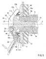
FIG.5 is a sectional view taken along arrows (V)-(V) ofFIG.4 and is a vertical sectional view of the fixing device. -
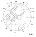
FIG.6 is an enlarged view of a portion (VI) inFIG.3 and is a vertical sectional view of a friction-reducing element. -
FIG.7 is a side view of the lever. It can be understood from this figure that a direction of application of a centrifugal force differs according to the relation between a position of the center of gravity of the lever and four areas sectioned under given conditions. -
FIG.8 is a vertical sectional view of the fixing device and its surroundings. It can be understood from this figure that a cutting depth when performing an oblique cutting operation differs depending on the size of the fixing device. - Next, an embodiment of the present invention will be described with reference to
FIGS. 1 to 8 . FIG. shows a portablecircular saw 1 with acircular saw blade 2 fixed by using afixing device 10 of this embodiment. The present embodiment exemplifies the portable circular saw 1 as an example of rotary tools, and thecircular saw blade 2 as an example of rotary blades. The constitution of theportable circular saw 1 itself is similar to that known in the prior art and requires no particular modification in the present embodiment. The periphery of an upper half circumference of thesaw blade 2 is covered with ablade case 3. A driving motor and a speed-reducing mechanism is located at the backside of thisblade case 3. An output of this driving motor is transmitted via the speed-reducing mechanism into aspindle 5 protruding into the blade case. In order to fix thesaw blade 2 to thisspindle 5, thefixing device 10 is used as described below.
Symbol 4 inFIG.1 designates a base adapted to contact with a cut material W. Theblade case 3 is supported on the upper surface of thisbase 4, and the lower side of thesaw blade 2 protrudes on a lower surface side of thisbase 4. The cut material is cut by this protruding portion. Theblade case 3 is supported by the base so as to be capable of tilting upward and downward, so that a protruding distance of the saw blade can be changed for adjusting a cutting depth for the cut material. Further, theblade case 3 is supported on thebase 4 so as to be capable of tilting in right and left directions with respect to a cutting direction (a direction intersecting the sheet face). Normally, by tilting theblade case 3 in the direction of displacing the upper side of thesaw blade 2 toward a front side (right side with respect to a cutting proceeding direction), a so-called oblique cutting operation can be performed. Also for these cutting-depth adjustment mechanism and oblique-cutting mechanism, techniques known in the art are used. - The details about the
fixing device 10 of the present embodiment are illustrated inFIG.2 and its subsequent figures. This fixingdevice 10 is provided with anouter flange 11 and aninner flange 12 which clamp thesaw blade 2, and ascrew body 20. Both theouter flange 11 and theinner flange 12 are mounted to twosurface width portions spindle 5 so as to be non-rotatable relative to thespindle 5. Theouter flange 11 is brought to contact with an outer side (left side surface inFIGS.3 and5 ) of thesaw blade 2, and theinner flange 12 is brought to contact with an inner side surface (right side surface inFIGS. 3 and5 ).
Theinner flange 12 is provided with aboss portion 12a. Thisboss portion 12a is inserted into a mounting-hole 2a of thesaw blade 2 without a play.
Thescrew body 20 is provided with ascrew shaft portion 21 tightened into a screw-hole 5a of thespindle 5, and screwflange portion 22 extending from a head side (left end side inFIG.3 ) of thisscrew shaft portion 21 to its surrounding.
Thescrew flange portion 21 has a truncated cone shape with its outer circumference surface (conical surface) inclined in such a direction that its diameter increases toward theouter flange 11. An operatinglever 24 is supported on the outer surface side of thisscrew flange 22 via asupport shaft 23 so as to be operable to pivot. Around thesupport shaft 23, atorsion spring 25 is interposed between the operatinglever 24 and thescrew flange portion 22. Through thistorsion spring 25 the operatinglever 24 is biased toward the side of its storage position (a position illustrated inFIGS.2 and3 ) that will be described later.
A lever receivingconcave part 30 is provided on the outer surface of thescrew flange portion 22. As illustrated inFIG.3 , when the operatinglever 24 is situated in its storage position, it is received within the lever receivingconcave part 30 without protruding from aconical surface 22a. On the contrary, when the operatinglever 24 is taken out to its use position against thetorsion spring 25 as illustrated inFIG.5 , a substantial part of the operating lever protrudes from thelever receiving portion 30 to result in a state of largely protruding radially from thescrew flange portion 22. If the user takes out the operatinglever 24 too its use position against thetorsion spring 25 with fingertips and then releases the fingertips in the state of the lever being taken out to this use position, the operatinglever 24 returns to its storage position by thetorsion spring 25. - As illustrated in
FIGS.3 and5 , a leading end side of the operatinglever 24 is covered with aresin cover 24a. Further, as illustrated inFIGS.2 and4 , a width size on the leading end side of the operatinglever 24 decreases gradually. Meanwhile, an upper portion as viewed inFIGS.2 and4 of thescrew flange portion 22 is removed (removedportion 22b), and therefore, in the state where the operatinglever 24 is situated in its received position (the state shown inFIG.2 ), its leading portion slightly protrudes from the removedportion 22b of thescrew flange portion 22. The user can pinch this protruding portion with fingertips in order to easily take the operatinglever 24 out of its received position into its use position.
The operatinglever 24 has a shape bent into a substantially angle shape (V shape) to conform to the truncated cone shape of thescrew flange portion 22, and is provided with a receivingbase 24b having an angle-shaped (V-shaped) cross section around its bent leading end. As illustrated inFIG.5 , when the operatinglever 24 is taken out to its use position, this receivingbase 24b closely fits into a receivingconcave part 30a having a substantially angle shape (V shape) and formed at the bottom of the lever receivingconcave part 30, and therefore, an external force applied in a taking-out direction to the operatinglever 24 taken out to its use position (a pressing force in the direction indicated by an outline arrow shown inFIG.5 ) can be received at thescrew flange portion 22.
Further, the width size of the operatinglever 24 is set to have such a width size that enables to be received in the lever receivingconcave part 30 without a play. Therefore, in a state where the operatinglever 24 is taken out to its use position as illustrated inFIG.4 , the operatinglever 24 fits into the lever receivingconcave part 30 without a play with respect to the width direction. Hence, when an external force is applied in a screw-rotating direction to the operatinglever 24 which is taken out to its use position (in the direction indicated by the outline arrow shown inFIG.4 ), this force is received at either side of the lever housingconcave part 30, so that a load applied to the side of thesupport shaft 23 is reduced. - A friction-reducing
element 40 is clamped between thescrew flange 22 and theouter flange 11. The details of this friction-reducingelement 40 are illustrated inFIG.6 . This friction-reducingelement 40 is provided with a number of steel balls 41-41, a retainingring 42 which retains the steel balls at regular intervals on the same circle about an axis line J, and ametal cover 43 which restricts a positional offset of these steel balls in the direction of the axis line J. Eachsteel ball 41 fits into a rollingmotion groove 11a provided in theouter flange 11.
Further, themetal cover 43 has an annular shape along the retainingring 42 and is provided with a rollingmotion groove 43a disposed on its side surface and facing the aboverolling motion groove 11a in theouter flange 11. Eachsteel ball 41 also fits into this rollingmotion groove 43a. Eachsteel ball 41 is held between the rollingmotion groove 11a in theouter flange 11 and the rollingmotion groove 43a in themetal cover 43.
Further, anengagement groove 43c is formed in the inner circumference of themetal cover 43 over its entire circumferences. Facing thisengagement groove 43c, anengagement groove 11b is formed in the outer circumference of aboss portion 11c of theouter flange 11 over its entire circumferences. Arubber ring 44 is fitted to extend between both theengagement groove 43c in themetal cover 43 and theengagement groove 11b in theouter flange 11. By way of thisrubber ring 44, themetal cover 43 is retained on the outer circumference side of theboss portion 11c of theouter flange 11, and eventually the friction-reducingelement 40 is retained.
During the relative rotation of thescrew flange 22 to theouter flange 11 accompanying the movement for tightening and loosening thescrew body 20 with respect to thespindle 5, eachsteel ball 41 rolls along the rollingmotion groove 11a and the friction between both 22 and 11 is considerably reduced, and hence thescrew body 20 can be tightened firmly against thescrew hole 5a of thespindle 5 with a small operating force, and can be loosened in an opposite manner. - Next, the shape of the operating
lever 24 or its weight distribution is set appropriately so that the position of a gravity center G of the operatinglever 24 meets the following condition. As illustrated inFIG.7 , assuming four areas (A), (B), (C) and (D) sectioned by the axis line J (the axis line for rotation of the spindle 5) of thescrew shaft portion 21 of thescrew body 20 and by a reference line H perpendicular to this axis line J and passing through the rotational center of the operating lever 24 (an axis line of the support shaft 23), the position of the gravity center G of the operatinglever 24 situated at the received position is set to be placed within the area (B) or (D). In the present embodiment, the shape of the operatinglever 24 or its weight distribution is appropriately set so that the gravity center G of the operatinglever 24 is placed within the area (B) and proximal to the receivingbase 24b having the angle shape.
Since the position of the center of gravity G of the operatinglever 24 is set as such, a centrifugal force produced while thesaw blade 2 rotates at a high speed is applied as a force retaining the operatinglever 24 in the received position (in a clockwise direction indicated by an outline arrow inFIG.7 ). This enables the operatinglever 24 to be retained firmly in the received position without need of additionally providing a retaining means such as a plunger, etc., and hence, it is possible to reliably prevent the operatinglever 24 from being accidental pivoted toward a raising direction (toward the use position side) accompanying the high-speed rotation of thesaw blade 2. - According to the fixing
device 10 of the present embodiment constituted as described above, thescrew body 20 is provided with the operatinglever 24, and this operatinglever 24 protrudes further outward from the periphery of thescrew flange 22 of thescrew body 20 when this operatinglever 24 is taken out to the use position. Therefore, a user can rotate thescrew body 20 by holding this operatinglever 24 with fingertips. In this case, a greater torque can be applied to thescrew flange 22 than in the case that the screw body is rotated by merely pinching thescrew flange 22, and therefore, thescrew body 20 can be tightened firmly against thespindle 5 and it is possible to reliably fix thesaw blade 2.
Further, since thescrew body 20 can be rotated in the loosening direction of thescrew body 20 by the use of the operatinglever 24 protruding outward from thescrew flange 22, a user can loosen thescrew body 22 by applying a large torque to it with a small operating force, and therefore, an operation for replacing thesaw blade 2, etc. can be easily carried out.
Further, according to the fixingdevice 10 of the present embodiment, thescrew flange 22 of thescrew body 20 has a truncated cone shape and theouter flange 11 is located in the state where theouter flange 11 is substantially received within thisscrew flange 22 having the truncated cone shape, so that a protruding distance from thesaw blade 2 of the fixingdevice 10 is smaller than that in the prior art and its overall configuration is of substantially truncated cone shape. - Considering this respect, even in the case that the rotational axis line (screw axis J) of the
saw blade 2 is set to be nearer to the base 4 (low position) in height and a protruding distance (cutting depth) of thesaw blade 2 toward the lower surface side of thebase 4 is set to be large, a circular saw body (circular saw 2) can be tilted by 50 degrees with respect to thebase 4 the same way in the prior art while avoiding interference with thebase 4 of the fixingdevice 10, and therefore, according to the fixingdevice 10 of the present embodiment, the cutting depth of the saw blade 2 (the protruding distance from the lower surface of the base 4) can be set to be larger by setting the rotational axis line J to be lower without sacrificing an inclination angle when an oblique cutting operation is performed. This respect is shown inFIG.8 .
InFIG.8 , a fixingdevice 50 is illustrated to have acylindrical part 51 that is large in thickness T1 as its whole configuration due to a cylindrical outer flange having a relatively large thickness size, which is different from theouter flange 11 of the fixingdevice 10 of the illustrated embodiment, and other members. In the case of this fixingdevice 50, even in the case that a protruding distance T0 from thesaw blade 2 and a radial size are the same as those of the fixingdevice 10 of the present embodiment, the protruding amount from theconical surface 22a of theflange 22 of the present embodiment becomes large as illustrated in the figure by two-dot chain lines, and therefore, it is necessary to keep an inclination angle of 50 degrees in the case of an oblique cutting operation by increasing the height of the center of the screw axis line J (rotational center of the saw blade 2) from thebase 4 by an amount corresponding to the protruding amount, and hence, a cutting depth K1 of thesaw blade 2 becomes smaller than a cutting depth K0 in the case of the fixingdevice 10 of the present embodiment. - In this way, according to the fixing
device 10 of the present embodiment, a user can take the operatinglever 24 out into the use position and rotate the screw body via the operatinglever 24 while retaining the operating lever in this use position, and therefore, the user can rotate the screw body with a large torque (operating force) by a smaller force than that in the case of rotating thescrew flange 22 of thescrew body 20 by pinching it directly with fingertips. Therefore, the user can firmly fix the rotary blade by firmly tightening thescrew body 20 against the spindle without use of a special tool such as a driver for screw driving.
On the other hand, the user can loosen the screw body in the loosening direction with a small force by the use of the operating lever, and therefore, the user can easily carry out the operation for replacing the rotary blade.
Further, thescrew flange 22 constructed to have the receivingconcave part 30 in which the operatinglever 24 is received not to protrude from the outer surface (conical surface) of thescrew flange 22, and therefore, the protruding distance T0 from thesaw blade 2 can be made as small as possible. In addition, since the outer surface of thescrew flange 22 is formed into a truncated cone, the size in the radial direction of the fixing device 10 (in the direction along a surface direction of the saw blade 2) can be made to be substantially small. For this reason, an inclination angle achieved when performing an oblique cutting operation by an existing portablecircular saw 1 can be ensured while the cutting depth can be ensured to be sufficient as in the prior art.
As explained above, according to the fixingdevice 10 of the present embodiment, while ensuring a cutting depth to be sufficient when performing an oblique cutting operation(without sacrificing a cutting depth), a user can fix thesaw blade 2 firmly with a small force by being provided with the operatinglever 24 for the rotational operation, and on the other hand, a user can easily remove it with a small force. Therefore, by applying the fixingdevice 10 to an existing portablecircular saw 1, it is possible to make the saw to be tool-less. - Also, according to the illustrated
fixing device 10, thelever 24 is configured to be operated to pivot about thesupport shaft 23, and in the state where the operatinglever 24 is taken out to its use position, the receivingbase 24b is fitted in the receivingconcave part 30a on theouter flange 11 side and is able to adequately receive a pressing force applied to the operatinglever 24 in the direction indicated by the outline arrow inFIG.5 . For this reason, a user can rotate thescrew body 20 in the tightening or loosening direction via the operatinglever 24 while retaining it in its use position by pressing the operatinglever 24 lightly with fingertips in the same direction. In this respect, good usability (operability for rotation) is ensured with respect to the rotational operation of thescrew body 20 by the fixingdevice 10 of this embodiment.
Further, when the operatinglever 24 is taken out to its use position, both sides of the lever in the width direction are brought into the state of fitting between both sides of the lever receivingconcave part 30 without substantial play, and therefore, it results in a state where a play in the rotational direction of the screw axis is eliminated or reduced. For this reason, compared with a case where the entire operational force applied to the operatinglever 24 in the rotational direction of the screw axis (in the direction indicated by the outline arrows inFIG.4 ) is received by thesupport shaft 23 side, the operability for rotation of the operatinglever 24 can be ensured with durability of thesupport shaft 23 being ensured. - Various modifications can be made to the embodiment explained above. For example, although the construction in which the
steel balls 41 to 41 are used as a friction-reducing element was illustrated, instead of this construction, a construction using needle rollers or a construction of simply inserting liners having high sliding ability may be used.
Further, by an application of high-friction-coefficient treatment such as an application of a coating material containing a hard heavy metal on the surfaces (bearing surfaces) of theouter flange 11 and theinner flange 12 contacting with thesaw blade 2, the friction-coefficient of bothflanges saw blade 2 can be increased, so that sliding of thesaw blade 2 can be prevented more reliably.
Further, although the portable circular saw was exemplified as a rotary tool and the saw blade was exemplified as a rotary blade, the fixing device of the present invention can be extensively applied as fixing bolts for fix rotary blades for the other rotary tools, such as a desktop type circular saw machine or a hand-held grinder.
Claims (9)
- A device for fixing a rotary blade to a spindle of a rotary tool, comprising:an outer flange and an inner flange for clamping said rotary blade; anda screw body having a screw shaft portion and a screw flange, said screw axis portion being tightened into a screw hole of said spindle, said screw flange being extended from a head side of said screw shaft portion to the circumference and pressed against an outer surface side of said outer flange; wherein:said screw flange has a truncated cone shape having a larger diameter on the side of said outer flange and has an operating lever on its outer surface, the operating lever being operable to pivot between a received position and a use position by the pivotal operation in front and back reverting directions; andwhen the operation lever is pivoted to the received position, said operating lever is received within a lever receiving concave part provided at the outer surface of said truncated cone and is received in a state where its leading end side does not protrude from a peripheral edge of the screw flange, and when the lever is pivoted to said use position, the lever is brought into a state where the leading end side protrudes from the peripheral edge of the screw flange in a radial direction.
- The fixing device according to claim 1, wherein said operating lever is received within said lever receiving concave part in a state where it does not protrude from the outer surface of said truncated cone of the screw flange.
- The fixing device according to claim 2, wherein said operating lever is biased toward the side of said received position.
- The fixing device according to claim 1, wherein a friction-reducing element is interposed between said screw flange and said outer flange for reducing the friction resistance therebetween in a rotational direction.
- The fixing device according to claim 1, wherein said outer flange and said inner flange are fixed to said spindle with respect to the rotation about an axis line of the spindle.
- The fixing device accordance to claim 1, wherein the rotary blade is mounted coaxially to said spindle by inserting a boss portion of said inner flange into a mounting hole of said rotary blade.
- The fixing device according to claim 1, wherein the fixing device is constructed such that said operating lever is supported so as to be operable to pivot between said received position and said use position relative to said screw flange via a support shaft, and when said operating lever is taken out to said use position, a receiving base having an angle shape in section is brought to contact with a receiving concave part provided at said receiving concave part, so that an external force in a taking out direction toward said use position applied to said operating lever is received at two points of the receiving base and said support shaft.
- The fixing device according to claim 1, wherein the fixing device is constructed so that in the state where said operating lever is taken out to said use position, side surfaces of the operating lever in the width direction are brought to contact with either side of said receiving concave part in the width direction, so that an external force applied to the operating lever in a screw-rotating direction can be received.
- The fixing device according to claim 1, wherein in order to make a centrifugal force produced by the rotation of said spindle to act as an external force in a direction for retaining said operating lever on the side of said received position, a weight distribution of the operating lever is set so that a gravity center of the operating lever is situated in an area (B) (D) out of four areas (A), (B), (C) and (D) sectioned by a rotational axis J of said spindle and a reference line H perpendicular to this rotational axis J and passing through a support shaft rotatably supporting the operating lever.
Applications Claiming Priority (2)
| Application Number | Priority Date | Filing Date | Title |
|---|---|---|---|
| JP2007081278A JP4964642B2 (en) | 2007-03-27 | 2007-03-27 | Rotating blade fixing device |
| PCT/JP2008/055230 WO2008117741A1 (en) | 2007-03-27 | 2008-03-21 | Locking device for rotary cutting tool |
Publications (2)
| Publication Number | Publication Date |
|---|---|
| EP2127794A1 true EP2127794A1 (en) | 2009-12-02 |
| EP2127794A4 EP2127794A4 (en) | 2012-07-11 |
Family
ID=39788476
Family Applications (1)
| Application Number | Title | Priority Date | Filing Date |
|---|---|---|---|
| EP08722594A Withdrawn EP2127794A4 (en) | 2007-03-27 | 2008-03-21 | Locking device for rotary cutting tool |
Country Status (4)
| Country | Link |
|---|---|
| US (1) | US8366366B2 (en) |
| EP (1) | EP2127794A4 (en) |
| JP (1) | JP4964642B2 (en) |
| WO (1) | WO2008117741A1 (en) |
Cited By (3)
| Publication number | Priority date | Publication date | Assignee | Title |
|---|---|---|---|---|
| CN102441705A (en) * | 2010-10-04 | 2012-05-09 | 株式会社牧田 | Cutting machine |
| DE102015001146B4 (en) * | 2014-01-30 | 2020-10-08 | Makita Corporation | Cutting device |
| DE102021213514A1 (en) | 2021-11-30 | 2023-06-01 | Robert Bosch Gesellschaft mit beschränkter Haftung | Tool fixture, machine tool, machine tool system and tool means |
Families Citing this family (7)
| Publication number | Priority date | Publication date | Assignee | Title |
|---|---|---|---|---|
| US7904346B2 (en) * | 2002-12-31 | 2011-03-08 | Ebay Inc. | Method and system to adjust a seller fixed price offer |
| JP2014131824A (en) | 2013-01-07 | 2014-07-17 | Makita Corp | Work tools |
| EP3476539A1 (en) * | 2017-10-27 | 2019-05-01 | HILTI Aktiengesellschaft | Tensioning device and handheld machine tool |
| JP7096032B2 (en) | 2018-03-28 | 2022-07-05 | 株式会社マキタ | Multi tool |
| US10875109B1 (en) | 2018-04-30 | 2020-12-29 | Kreg Enterprises, Inc. | Adaptive cutting system |
| US20200070266A1 (en) * | 2018-08-29 | 2020-03-05 | Illinois Tool Works Inc. | Retention apparatus for material removal machines |
| CN118024358A (en) * | 2020-06-25 | 2024-05-14 | 费斯托工具有限责任公司 | Handheld circular saw with improved cutting capabilities |
Family Cites Families (20)
| Publication number | Priority date | Publication date | Assignee | Title |
|---|---|---|---|---|
| DE1936720A1 (en) * | 1969-07-18 | 1971-02-04 | Heinrich Schaller Fa | Elastic quick-change chuck for high-speed grinding wheels |
| US4005622A (en) * | 1976-04-30 | 1977-02-01 | Bassett Alvin L | Circular saw wrench |
| DE3623555A1 (en) * | 1986-07-12 | 1988-02-04 | Fein C & E | FASTENING DEVICE FOR DISC-SHAPED TOOLS ON THE TOOL SPINDLE OF A PORTABLE ELECTRIC TOOL MACHINE |
| DE3741484C1 (en) * | 1987-12-08 | 1989-08-24 | Fein C & E | Hand machine tool with automatic locking of the work spindle |
| JPH02145211A (en) | 1988-11-28 | 1990-06-04 | Zhdanovskij Metall Inst | Device for cramping circular saw blade |
| DE3902874A1 (en) * | 1989-02-01 | 1990-08-09 | Fein C & E | ADAPTER FOR ATTACHING AN ADDITIONAL TOOL |
| HUT70006A (en) | 1990-09-12 | 1995-09-28 | Matthews | Fastener particularly for grinding wheel |
| US5075976A (en) * | 1991-02-05 | 1991-12-31 | Young Peter W | Power tool guard retainer |
| DE4336620C2 (en) * | 1993-10-27 | 1997-07-03 | Fein C & E | Power tool with a clamping device that can only be operated when the engine is switched off |
| JPH07299743A (en) * | 1994-05-10 | 1995-11-14 | Ryobi Ltd | Tool tightening device |
| DE19649514A1 (en) | 1996-11-29 | 1998-06-04 | Bosch Gmbh Robert | Hand tool |
| US5947671A (en) * | 1998-01-30 | 1999-09-07 | Power Tool Holders Incorporated | Hand actuable clamping device with circumferentially extending tightening members |
| US7013987B2 (en) * | 2000-09-08 | 2006-03-21 | Black & Decker | Clutch assembly and clamp mechanism for rotary tool disc |
| DE10059976A1 (en) | 2000-12-02 | 2002-06-06 | Bosch Gmbh Robert | Hand tool |
| DE10124971B4 (en) | 2001-05-21 | 2013-06-20 | Hilti Aktiengesellschaft | Quick clamping device for a circular saw |
| DE10258372B4 (en) * | 2001-12-12 | 2004-12-30 | S-B Power Tool Company, Broadview | tensioning assembly |
| US7343841B2 (en) * | 2002-02-15 | 2008-03-18 | Black & Decker Inc. | Blade clamp assembly |
| EP1375094A1 (en) * | 2002-06-18 | 2004-01-02 | Black & Decker Inc. | Clamp mechanism and clutch assembly for rotary tool disc |
| TWM273437U (en) * | 2004-12-10 | 2005-08-21 | Rexon Ind Corp Ltd | Device for securing saw blade to motor of power tool |
| GB0515575D0 (en) * | 2005-07-29 | 2005-09-07 | Gmca Pty Ltd | Clamping apparatus |
-
2007
- 2007-03-27 JP JP2007081278A patent/JP4964642B2/en not_active Expired - Fee Related
-
2008
- 2008-03-21 EP EP08722594A patent/EP2127794A4/en not_active Withdrawn
- 2008-03-21 US US12/450,354 patent/US8366366B2/en not_active Expired - Fee Related
- 2008-03-21 WO PCT/JP2008/055230 patent/WO2008117741A1/en not_active Ceased
Cited By (4)
| Publication number | Priority date | Publication date | Assignee | Title |
|---|---|---|---|---|
| CN102441705A (en) * | 2010-10-04 | 2012-05-09 | 株式会社牧田 | Cutting machine |
| CN102441705B (en) * | 2010-10-04 | 2014-08-27 | 株式会社牧田 | Cutting machine |
| DE102015001146B4 (en) * | 2014-01-30 | 2020-10-08 | Makita Corporation | Cutting device |
| DE102021213514A1 (en) | 2021-11-30 | 2023-06-01 | Robert Bosch Gesellschaft mit beschränkter Haftung | Tool fixture, machine tool, machine tool system and tool means |
Also Published As
| Publication number | Publication date |
|---|---|
| JP4964642B2 (en) | 2012-07-04 |
| US20100047036A1 (en) | 2010-02-25 |
| US8366366B2 (en) | 2013-02-05 |
| WO2008117741A1 (en) | 2008-10-02 |
| JP2008238321A (en) | 2008-10-09 |
| EP2127794A4 (en) | 2012-07-11 |
Similar Documents
| Publication | Publication Date | Title |
|---|---|---|
| US8366366B2 (en) | Fixing device for rotary blade | |
| US10478943B2 (en) | Grinder, cover and cover set | |
| CN100506481C (en) | Electric hand tool machine | |
| EP1878525B1 (en) | Cutter | |
| US8403730B2 (en) | Stopper device for grinding stone cover of grinder | |
| JPH01281874A (en) | Portable type grinder with adjustable protective hood | |
| GB2436438A (en) | Mounting a hood on a portable power tool | |
| EP2447003B1 (en) | Disc grinders | |
| US20030000717A1 (en) | Hand machine tool comprising two cutting disks, which rotate counter and immediately adjacent to one another, and means for chucking the cutting disks for a hand machine tool of this type | |
| US6663475B2 (en) | Grinding apparatus | |
| US20130149943A1 (en) | Device for preventing removal of a fixing member of a whetstone cover in a disc grinder | |
| JPH10505794A (en) | Hand-held electric machine tool | |
| US8006777B2 (en) | Hand-held power tool | |
| US9050670B2 (en) | Pipe disconnecting device | |
| KR20190091168A (en) | Multifunction cutting machine | |
| JP2025088951A (en) | blade sharpening device | |
| JP2011245564A (en) | Position adjusting mechanism of movable cover in cutting tool | |
| US20010037576A1 (en) | Gear head | |
| JP2007175957A (en) | Electric cutting tool | |
| KR20040077237A (en) | grinding material fixing jig | |
| JP4849836B2 (en) | Pipe cutting and chamfering machine | |
| JP2008284677A (en) | Machining tools | |
| JP7237275B1 (en) | Electric cutting machine with dust cover | |
| US20240351234A1 (en) | Cutter | |
| JP3599997B2 (en) | Rotating blade mounting structure |
Legal Events
| Date | Code | Title | Description |
|---|---|---|---|
| PUAI | Public reference made under article 153(3) epc to a published international application that has entered the european phase |
Free format text: ORIGINAL CODE: 0009012 |
|
| 17P | Request for examination filed |
Effective date: 20090922 |
|
| AK | Designated contracting states |
Kind code of ref document: A1 Designated state(s): AT BE BG CH CY CZ DE DK EE ES FI FR GB GR HR HU IE IS IT LI LT LU LV MC MT NL NO PL PT RO SE SI SK TR |
|
| DAX | Request for extension of the european patent (deleted) | ||
| A4 | Supplementary search report drawn up and despatched |
Effective date: 20120611 |
|
| RIC1 | Information provided on ipc code assigned before grant |
Ipc: B23D 61/10 20060101AFI20120604BHEP Ipc: B23B 31/02 20060101ALI20120604BHEP Ipc: B27B 5/32 20060101ALI20120604BHEP Ipc: B27B 9/00 20060101ALI20120604BHEP Ipc: B23D 47/00 20060101ALI20120604BHEP |
|
| RIN1 | Information on inventor provided before grant (corrected) |
Inventor name: KOJIMA, NAOYUKI Inventor name: HIRABAYASHI, SHINJI |
|
| STAA | Information on the status of an ep patent application or granted ep patent |
Free format text: STATUS: THE APPLICATION HAS BEEN WITHDRAWN |
|
| 18W | Application withdrawn |
Effective date: 20150306 |