EP2127734A1 - Mixing assembly comprising a mixing chamber and an overflow chamber and process for mixing - Google Patents
Mixing assembly comprising a mixing chamber and an overflow chamber and process for mixing Download PDFInfo
- Publication number
- EP2127734A1 EP2127734A1 EP08157054A EP08157054A EP2127734A1 EP 2127734 A1 EP2127734 A1 EP 2127734A1 EP 08157054 A EP08157054 A EP 08157054A EP 08157054 A EP08157054 A EP 08157054A EP 2127734 A1 EP2127734 A1 EP 2127734A1
- Authority
- EP
- European Patent Office
- Prior art keywords
- mixing chamber
- mixing
- chamber
- overflow channel
- liquid
- Prior art date
- Legal status (The legal status is an assumption and is not a legal conclusion. Google has not performed a legal analysis and makes no representation as to the accuracy of the status listed.)
- Withdrawn
Links
Images

Classifications
-
- A—HUMAN NECESSITIES
- A47—FURNITURE; DOMESTIC ARTICLES OR APPLIANCES; COFFEE MILLS; SPICE MILLS; SUCTION CLEANERS IN GENERAL
- A47J—KITCHEN EQUIPMENT; COFFEE MILLS; SPICE MILLS; APPARATUS FOR MAKING BEVERAGES
- A47J31/00—Apparatus for making beverages
- A47J31/40—Beverage-making apparatus with dispensing means for adding a measured quantity of ingredients, e.g. coffee, water, sugar, cocoa, milk, tea
- A47J31/401—Beverage-making apparatus with dispensing means for adding a measured quantity of ingredients, e.g. coffee, water, sugar, cocoa, milk, tea whereby the powder ingredients and the water are delivered to a mixing bowl
-
- B—PERFORMING OPERATIONS; TRANSPORTING
- B01—PHYSICAL OR CHEMICAL PROCESSES OR APPARATUS IN GENERAL
- B01F—MIXING, e.g. DISSOLVING, EMULSIFYING OR DISPERSING
- B01F21/00—Dissolving
- B01F21/20—Dissolving using flow mixing
-
- B—PERFORMING OPERATIONS; TRANSPORTING
- B01—PHYSICAL OR CHEMICAL PROCESSES OR APPARATUS IN GENERAL
- B01F—MIXING, e.g. DISSOLVING, EMULSIFYING OR DISPERSING
- B01F23/00—Mixing according to the phases to be mixed, e.g. dispersing or emulsifying
- B01F23/40—Mixing liquids with liquids; Emulsifying
- B01F23/45—Mixing liquids with liquids; Emulsifying using flow mixing
- B01F23/452—Mixing liquids with liquids; Emulsifying using flow mixing by uniting flows taken from different parts of a receptacle or silo; Sandglass-type mixing
-
- B—PERFORMING OPERATIONS; TRANSPORTING
- B01—PHYSICAL OR CHEMICAL PROCESSES OR APPARATUS IN GENERAL
- B01F—MIXING, e.g. DISSOLVING, EMULSIFYING OR DISPERSING
- B01F35/00—Accessories for mixers; Auxiliary operations or auxiliary devices; Parts or details of general application
- B01F35/50—Mixing receptacles
- B01F35/52—Receptacles with two or more compartments
-
- B—PERFORMING OPERATIONS; TRANSPORTING
- B01—PHYSICAL OR CHEMICAL PROCESSES OR APPARATUS IN GENERAL
- B01F—MIXING, e.g. DISSOLVING, EMULSIFYING OR DISPERSING
- B01F35/00—Accessories for mixers; Auxiliary operations or auxiliary devices; Parts or details of general application
- B01F35/75—Discharge mechanisms
- B01F35/753—Discharging at the upper side of the receptacle, e.g. by pressurising the liquid in the receptacle or by centrifugal force
-
- B—PERFORMING OPERATIONS; TRANSPORTING
- B01—PHYSICAL OR CHEMICAL PROCESSES OR APPARATUS IN GENERAL
- B01F—MIXING, e.g. DISSOLVING, EMULSIFYING OR DISPERSING
- B01F35/00—Accessories for mixers; Auxiliary operations or auxiliary devices; Parts or details of general application
- B01F35/75—Discharge mechanisms
- B01F35/754—Discharge mechanisms characterised by the means for discharging the components from the mixer
- B01F35/7542—Discharging the components by overflow
-
- B—PERFORMING OPERATIONS; TRANSPORTING
- B01—PHYSICAL OR CHEMICAL PROCESSES OR APPARATUS IN GENERAL
- B01F—MIXING, e.g. DISSOLVING, EMULSIFYING OR DISPERSING
- B01F2101/00—Mixing characterised by the nature of the mixed materials or by the application field
- B01F2101/06—Mixing of food ingredients
- B01F2101/14—Mixing of ingredients for non-alcoholic beverages; Dissolving sugar in water
-
- B—PERFORMING OPERATIONS; TRANSPORTING
- B01—PHYSICAL OR CHEMICAL PROCESSES OR APPARATUS IN GENERAL
- B01F—MIXING, e.g. DISSOLVING, EMULSIFYING OR DISPERSING
- B01F2101/00—Mixing characterised by the nature of the mixed materials or by the application field
- B01F2101/1805—Kitchen, household equipment for mixing
Definitions
- the present invention relates to a mixing assembly that provides a frothy product. More particularly, the invention relates to a mixing assembly for mixing, frothing and dispensing a beverage, and to a method for providing a frothy product.
- Many beverages like espresso and other coffee, milk drinks, soups, ... are often prepared by mixing a powder or a liquid concentrate with water.
- Mixing devices are known for speedier preparation of such beverages and other foods by mixing a powdered food component with a liquid, such as water. These devices typically feed the soluble component into the water, which is often pumped into a mixing chamber to create a whirlpool to mix the soluble component into the water and creates foam. The frothed mixture is then usually evacuated from the mixing chamber by gravimetry through the bottom of the mixing chamber and dispensed into a receptacle for drinking.
- the object of the present invention is to provide a new mixing assembly that avoids the above problem and enables the production of a frothed beverage that can be evacuated from the mixing chamber without leaving a part of foam in the mixing chamber and consequently without necessity to rinse the chamber with clear water after preparation of the beverage.
- the present invention concerns a mixing assembly comprising a mixing chamber adapted to mix a soluble ingredient with a diluent, wherein the mixing assembly comprises an overflow channel so that a liquid exceeding the capacity of the mixing chamber is able to flow in the overflow channel and wherein the outlets of the mixing chamber and the overflow channel allow the liquid contained in the mixing chamber and the overflow channel to exit and mix in the same place.
- the mixing assembly of the present invention comprises a mixing chamber which can be of any known kind and can take various shapes.
- the longitudinal upward wall is substantially cylindrical. Other shapes could be envisaged such as a polygonal, e.g., hexagonal, or oval section of the chamber, for instance.
- the bottom wall can be substantially a portion of truncated cone.
- the mixing chamber usually comprises an inlet opening for the introduction of soluble ingredient and of the diluent and an outlet for delivering the liquid mixed product issued from the dissolution of soluble ingredient.
- the inlet of the mixing chamber is on the top of the chamber so that soluble ingredient can be introduced by gravimetric fall inside the mixing chamber.
- the outlet of the mixing chamber is usually in the bottom of the mixing chamber.
- the mixing chamber inlet opening is placed below the metering device, that delivers the soluble ingredient, because it is advantageous to take profit of the gravity force to let soluble ingredient falls in the mixing chamber, yet any other introduction of soluble ingredient in other sides of the mixing chamber for example through a side opening is possible.
- the mixing chamber inlet opening is generally below the diluent feed opening because it is preferable to take profit of the gravity force to let diluent falls in the mixing chamber, yet any other introduction of diluent in other sides of the mixing chamber for example in a side opening is possible.
- no wall or restriction is provided on the top part the mixing chamber, so that any liquid falling inside the mixing chamber and exceeding the volume capacity of the mixing chamber can freely flow outside the mixing chamber by overflowing over the upward walls of the mixing chamber.
- the absence of top wall provides also a big and easy inlet for the introduction of soluble ingredient and diluent.
- the mixing chamber is rotor free
- the mixing chamber presents at least one outlet allowing the liquid to exit the mixing chamber.
- Said at least one outlet is usually placed in the bottom wall of the mixing chamber so that all mixed product is evacuated by gravimetry.
- the mixing assembly comprises an overflow channel so that the liquid exceeding the capacity of the mixing chamber is able to flow in the overflow channel.
- Said overflow channel can be a channel running along the external wall of the mixing chamber.
- the inlet of the overflow channel is generally placed at the top of the mixing chamber.
- the outlets of the mixing chamber and the overflow channel can mix before delivering the liquid in a final recipient.
- the outlet of the mixing chamber can be a pipe and the outlet of the overflow channel can emerge in said pipe. This configuration leads to a venturi effect when liquid flows simultaneously through the mixing chamber outlet and through the overflow channel outlet.
- This effect improves the suction of the liquid coming from the overflow channel.
- This embodiment is particularly interesting for liquid of which dilution creates foam because foam present on the top of the diluted liquid in the mixing chamber is mainly evacuated by the overflow channel and the venturi means improve the suction of said foam.
- the overflow channel is an overflow chamber surrounding the mixing chamber.
- the overflow chamber can be of any known kind and can take various shapes. Preferably, it presents the same form as the mixing chamber. It is placed relative to the mixing chamber so that the liquid overflowing from the mixing chamber falls directly into the overflow chamber.
- the overflow chamber presents at least one outlet allowing mixed product to exit the overflow chamber.
- Said at least one outlet is usually placed in the bottom wall of the overflow chamber so that the liquid is evacuated by gravimetry.
- the outlets of the mixing chamber and the overflow chamber allow the mixed product contained in the mixing chamber and the overflow chamber to exit and mix in the same place.
- the outlet(s) of the mixing chamber exit(s) in the overflow chamber.
- the total section of the outlet(s) of the mixing chamber is inferior or equal to the total section of the overflow chamber inlet so that most of the liquid introduced in the assembly evacuates through the overflow chamber rather than through the outlet(s) of the mixing chamber.
- the soluble ingredient when the soluble ingredient is introduced in the mixing chamber, it partially closes the outlet(s) of the mixing chamber before it is totally diluted ; this partial closure helps for creating the overflow of the liquid in the overflow channel or chamber. Then, all the foam is able to leave the assembly through the overflow channel rather than through the mixing chamber outlet(s).
- the assembly of the present invention is housed in a dispensing device.
- the invention concerns a process for mixing a soluble ingredient with a diluent using a mixing assembly as defined above comprising the steps of :
- the method applies either for a soluble ingredient that is a powder or a liquid concentrate. It is especially adapted for producing a diluted product with foam in particular food or beverage products like espresso coffee or frothed milk.
- the diluent is usually hot water.
- the production of foam inside the mixing chamber can be the result of the foaming nature of the soluble ingredient, it can also be improved by the way the diluent is introduced in the chamber, for example by the force of the diluent jet, and by the form of the mixing chamber or the presence of foaming device inside the chamber like a sieve or baffles.
- the diluent is introduced in a quantity and with a flow such that the liquid resulting from the dissolution of the soluble ingredient exceeds the capacity of the mixing chamber and flows partially in the overflow chamber.
- the control of said "overflowing" step is based on the properties of the mixing chamber that are its internal volume and the geometry of its outlet(s).
- the geometry of its outlet(s) defines the maximum flow at which the liquid can be evacuated from the mixing chamber.
- the diluent is introduced in the mixing chamber at a flow that is superior to the maximum flow at which the liquid can be evacuated from the mixing chamber and in a quantity that is superior to internal volume of the mixing chamber. In this way, the liquid level raises in the mixing chamber until it overflows.
- the foam that is produced floats on the liquid. Then, when the liquid exceeds the capacity of the mixing chamber, the foam is the first to fall inside the overflowing chamber and is then totally evacuated from the mixing chamber through the overflowing chamber. As the foam is the first to fall inside the overflowing chamber and is pushed by the liquid continuing to be introduced in the mixing chamber, no foam remains in the overflowing chamber : the latter is rinsed by the liquid overflowing the mixing chamber behind the foam. No foam is evacuated through the outlet(s) of the mixing chamber avoiding bubbles of foam to stay in the bottom of the mixing chamber.
- the quantity of diluent introduced in the mixing chamber must be sufficient to have all the foam leave the mixing chamber before stopping the introduction of diluent. This quantity can also be adapted according to the foaming capacity of the soluble ingredient
- Figures 1 and 2 illustrate a mixing assembly 1 according to the present invention comprising a mixing chamber 2 and an overflow channel 41 which runs along the external wall of the mixing chamber. Then liquid reaching the upper part of the mixing chamber can flow through the overflow channel.
- the mixing chamber 2 presents one outlet 3 in its bottom wall.
- the outlet 3 is a pipe in which the outlet 14 of the overflow channel 41 emerges.
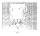
- Figure 3 illustrates a mixing assembly 1 according to the present invention comprising a mixing chamber 2 and an overflowing chamber 4 which surrounds the mixing chamber.
- the two chambers 2, 4 are concentric.
- a space 6 exists between the external wall of the mixing chamber 2 and the internal wall of the overflowing chamber 4 ; it enables the passage of the liquid that overflows from the mixing chamber 2.
- the top 41 of the overflowing chamber 4 is higher than the top 21 of the mixing chamber 2.
- the mixing chamber 2 presents one outlet 3 in its bottom wall emerging in the space 6 between the both chambers 2, 4.
- the overflowing chamber 4 presents one outlet 5 for evacuating the liquid coming from the outlet 3 of the mixing chamber 2 and the liquid and the foam overflowing from the mixing chamber 2.
- the mixing chamber 2 is fixed inside the overflowing chamber 4 by at least two pins 7 introduced in respective part of the mixing chambers.
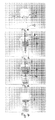
- Figures 4 to 7 illustrate the process for producing a foaming beverage with a mixing assembly of the present invention comprising an overflow chamber 2.
- First soluble ingredient 11 is introduced inside the mixing chamber 2 ( Fig. 4 ).
- diluent 8 is introduced in the mixing chamber 2 ( Fig. 5 ).
- the mixing of diluent and soluble ingredient 11 creates a liquid beverage 9 and foam 10 on the top of the liquid 9.
- the foam 10 overflows the mixing chamber 2 and enters the space 6 between the both chambers 2, 4. Simultaneously liquid beverage 9 flows through the mixing chamber outlet 3 and falls inside a receptacle 13.
Landscapes
- Chemical & Material Sciences (AREA)
- Chemical Kinetics & Catalysis (AREA)
- Engineering & Computer Science (AREA)
- Food Science & Technology (AREA)
- Apparatus For Making Beverages (AREA)
- Food-Manufacturing Devices (AREA)
- Tea And Coffee (AREA)
- Accessories For Mixers (AREA)
- Dairy Products (AREA)
Abstract
The invention also concerns a process for mixing a soluble ingredient with a diluent using the above mixing assembly.
Description
- The present invention relates to a mixing assembly that provides a frothy product. More particularly, the invention relates to a mixing assembly for mixing, frothing and dispensing a beverage, and to a method for providing a frothy product.
- Many beverages like espresso and other coffee, milk drinks, soups, ... are often prepared by mixing a powder or a liquid concentrate with water. Mixing devices are known for speedier preparation of such beverages and other foods by mixing a powdered food component with a liquid, such as water. These devices typically feed the soluble component into the water, which is often pumped into a mixing chamber to create a whirlpool to mix the soluble component into the water and creates foam. The frothed mixture is then usually evacuated from the mixing chamber by gravimetry through the bottom of the mixing chamber and dispensed into a receptacle for drinking.
- One problem that often arises when the soluble ingredient creates foam during its dissolution in the mixing chamber is that the foam is the last to be evacuated because it lays on the top of the liquid in the mixing chamber. A consequence is that the foam is often only partly evacuated, last bubbles of foam staying in the bottom of the mixing chamber. Then the mixing chamber must be rinsed by clear water and the beverage does not comprise all the produced foam.
- The object of the present invention is to provide a new mixing assembly that avoids the above problem and enables the production of a frothed beverage that can be evacuated from the mixing chamber without leaving a part of foam in the mixing chamber and consequently without necessity to rinse the chamber with clear water after preparation of the beverage.
- In a first aspect, the present invention concerns a mixing assembly comprising a mixing chamber adapted to mix a soluble ingredient with a diluent, wherein the mixing assembly comprises an overflow channel so that a liquid exceeding the capacity of the mixing chamber is able to flow in the overflow channel and wherein the outlets of the mixing chamber and the overflow channel allow the liquid contained in the mixing chamber and the overflow channel to exit and mix in the same place.
- The mixing assembly of the present invention comprises a mixing chamber which can be of any known kind and can take various shapes. In a preferred mode, the longitudinal upward wall is substantially cylindrical. Other shapes could be envisaged such as a polygonal, e.g., hexagonal, or oval section of the chamber, for instance. The bottom wall can be substantially a portion of truncated cone. The mixing chamber usually comprises an inlet opening for the introduction of soluble ingredient and of the diluent and an outlet for delivering the liquid mixed product issued from the dissolution of soluble ingredient. Usually, the inlet of the mixing chamber is on the top of the chamber so that soluble ingredient can be introduced by gravimetric fall inside the mixing chamber. The outlet of the mixing chamber is usually in the bottom of the mixing chamber. Generally the mixing chamber inlet opening is placed below the metering device, that delivers the soluble ingredient, because it is advantageous to take profit of the gravity force to let soluble ingredient falls in the mixing chamber, yet any other introduction of soluble ingredient in other sides of the mixing chamber for example through a side opening is possible. In the same way, the mixing chamber inlet opening is generally below the diluent feed opening because it is preferable to take profit of the gravity force to let diluent falls in the mixing chamber, yet any other introduction of diluent in other sides of the mixing chamber for example in a side opening is possible. In the preferred embodiment of the present invention, no wall or restriction is provided on the top part the mixing chamber, so that any liquid falling inside the mixing chamber and exceeding the volume capacity of the mixing chamber can freely flow outside the mixing chamber by overflowing over the upward walls of the mixing chamber. The absence of top wall provides also a big and easy inlet for the introduction of soluble ingredient and diluent. Preferably the mixing chamber is rotor free
- The mixing chamber presents at least one outlet allowing the liquid to exit the mixing chamber. Said at least one outlet is usually placed in the bottom wall of the mixing chamber so that all mixed product is evacuated by gravimetry.
- According to the present invention, the mixing assembly comprises an overflow channel so that the liquid exceeding the capacity of the mixing chamber is able to flow in the overflow channel. Said overflow channel can be a channel running along the external wall of the mixing chamber. The inlet of the overflow channel is generally placed at the top of the mixing chamber. Besides the liquid contained in the mixing chamber and the overflow channel exits and mixes in the same place. The outlets of the mixing chamber and the overflow channel can mix before delivering the liquid in a final recipient. For example, the outlet of the mixing chamber can be a pipe and the outlet of the overflow channel can emerge in said pipe. This configuration leads to a venturi effect when liquid flows simultaneously through the mixing chamber outlet and through the overflow channel outlet. This effect improves the suction of the liquid coming from the overflow channel. This embodiment is particularly interesting for liquid of which dilution creates foam because foam present on the top of the diluted liquid in the mixing chamber is mainly evacuated by the overflow channel and the venturi means improve the suction of said foam.
- According to the preferred embodiment, the overflow channel is an overflow chamber surrounding the mixing chamber. The overflow chamber can be of any known kind and can take various shapes. Preferably, it presents the same form as the mixing chamber. It is placed relative to the mixing chamber so that the liquid overflowing from the mixing chamber falls directly into the overflow chamber.
- The overflow chamber presents at least one outlet allowing mixed product to exit the overflow chamber. Said at least one outlet is usually placed in the bottom wall of the overflow chamber so that the liquid is evacuated by gravimetry.
- According to the present invention, the outlets of the mixing chamber and the overflow chamber allow the mixed product contained in the mixing chamber and the overflow chamber to exit and mix in the same place. According to a preferred embodiment, the outlet(s) of the mixing chamber exit(s) in the overflow chamber. Preferably the total section of the outlet(s) of the mixing chamber is inferior or equal to the total section of the overflow chamber inlet so that most of the liquid introduced in the assembly evacuates through the overflow chamber rather than through the outlet(s) of the mixing chamber. Generally, when the soluble ingredient is introduced in the mixing chamber, it partially closes the outlet(s) of the mixing chamber before it is totally diluted ; this partial closure helps for creating the overflow of the liquid in the overflow channel or chamber. Then, all the foam is able to leave the assembly through the overflow channel rather than through the mixing chamber outlet(s).
- Usually the assembly of the present invention is housed in a dispensing device.
- In a second aspect, the invention concerns a process for mixing a soluble ingredient with a diluent using a mixing assembly as defined above comprising the steps of :
- introducing the soluble ingredient in the mixing chamber,
- introducing the diluent in the mixing chamber in a quantity and with a flow such that the liquid resulting from the dissolution of the soluble ingredient exceeds the capacity of the mixing chamber and flows partially in the overflow chamber.
- The method applies either for a soluble ingredient that is a powder or a liquid concentrate. It is especially adapted for producing a diluted product with foam in particular food or beverage products like espresso coffee or frothed milk. The diluent is usually hot water. The production of foam inside the mixing chamber can be the result of the foaming nature of the soluble ingredient, it can also be improved by the way the diluent is introduced in the chamber, for example by the force of the diluent jet, and by the form of the mixing chamber or the presence of foaming device inside the chamber like a sieve or baffles.
- According to the process of the present invention, once the soluble ingredient has been introduced in the mixing chamber, the diluent is introduced in a quantity and with a flow such that the liquid resulting from the dissolution of the soluble ingredient exceeds the capacity of the mixing chamber and flows partially in the overflow chamber. The control of said "overflowing" step is based on the properties of the mixing chamber that are its internal volume and the geometry of its outlet(s). The geometry of its outlet(s) defines the maximum flow at which the liquid can be evacuated from the mixing chamber. Based on this maximum flow, the diluent is introduced in the mixing chamber at a flow that is superior to the maximum flow at which the liquid can be evacuated from the mixing chamber and in a quantity that is superior to internal volume of the mixing chamber. In this way, the liquid level raises in the mixing chamber until it overflows.
- During the step of introducing the diluent, the foam that is produced floats on the liquid. Then, when the liquid exceeds the capacity of the mixing chamber, the foam is the first to fall inside the overflowing chamber and is then totally evacuated from the mixing chamber through the overflowing chamber. As the foam is the first to fall inside the overflowing chamber and is pushed by the liquid continuing to be introduced in the mixing chamber, no foam remains in the overflowing chamber : the latter is rinsed by the liquid overflowing the mixing chamber behind the foam. No foam is evacuated through the outlet(s) of the mixing chamber avoiding bubbles of foam to stay in the bottom of the mixing chamber.
- The quantity of diluent introduced in the mixing chamber must be sufficient to have all the foam leave the mixing chamber before stopping the introduction of diluent. This quantity can also be adapted according to the foaming capacity of the soluble ingredient
- The characteristics and advantages of the invention will be better understood in relation to the figures which follow:
-
Figure 1 is a top view of a mixing assembly according to the present invention; -
Figure 2 is a sectional side view of the mixing assembly ofFigure 1 ; -
Figure 3 is a cross section view of the mixing assembly where the overflow channel is an overflow chamber; -
Figures 4 to 7 depict the process for producing a foaming beverage with the mixing assembly ofFigure 3 . -
Figures 1 and 2 illustrate a mixing assembly 1 according to the present invention comprising a mixing chamber 2 and anoverflow channel 41 which runs along the external wall of the mixing chamber. Then liquid reaching the upper part of the mixing chamber can flow through the overflow channel. The mixing chamber 2 presents oneoutlet 3 in its bottom wall. Theoutlet 3 is a pipe in which the outlet 14 of theoverflow channel 41 emerges. -
Figure 3 illustrates a mixing assembly 1 according to the present invention comprising a mixing chamber 2 and anoverflowing chamber 4 which surrounds the mixing chamber. The twochambers 2, 4 are concentric. A space 6 exists between the external wall of the mixing chamber 2 and the internal wall of the overflowingchamber 4 ; it enables the passage of the liquid that overflows from the mixing chamber 2. Preferably the top 41 of the overflowingchamber 4 is higher than the top 21 of the mixing chamber 2. The mixing chamber 2 presents oneoutlet 3 in its bottom wall emerging in the space 6 between the bothchambers 2, 4. The overflowingchamber 4 presents one outlet 5 for evacuating the liquid coming from theoutlet 3 of the mixing chamber 2 and the liquid and the foam overflowing from the mixing chamber 2. The mixing chamber 2 is fixed inside the overflowingchamber 4 by at least two pins 7 introduced in respective part of the mixing chambers. -
Figures 4 to 7 illustrate the process for producing a foaming beverage with a mixing assembly of the present invention comprising an overflow chamber 2. Firstsoluble ingredient 11 is introduced inside the mixing chamber 2 (Fig. 4 ). Then, diluent 8 is introduced in the mixing chamber 2 (Fig. 5 ). The mixing of diluent andsoluble ingredient 11 creates aliquid beverage 9 and foam 10 on the top of theliquid 9. The foam 10 overflows the mixing chamber 2 and enters the space 6 between the bothchambers 2, 4. Simultaneouslyliquid beverage 9 flows through the mixingchamber outlet 3 and falls inside areceptacle 13. As described inFigure 6 , so much diluent 8 is introduced in the mixing chamber 2 that the mixing chamber is full of liquid and all the foam is evacuated from the mixing chamber through the overflowingchamber 4. A part of theliquid beverage 9 is also evacuated from the mixing chamber through the overflowingchamber 4 after the foam. This liquid beverage rinses the space 6 between thechambers 2, 4 preventing any bubbles from staying in said space 6. Lastly, the introduction of diluent is stopped and the rest ofliquid 9 is evacuated from the mixing chamber 2 through the mixing chamber outlet 3 (Figure 7 ). No foam stays in the mixing chamber since it has been evacuated by the top of said chamber and the liquid beverage has totally rinsed the mixing chamber. No foam stays in the overflow chamber since it has been evacuated first from said chamber and the liquid beverage has rinsed said chamber after the passage of the foam.
Claims (10)
- A mixing assembly 1 comprising a mixing chamber (2) adapted to mix a soluble ingredient with a diluent, wherein the mixing assembly comprises an overflow channel (41) so that a liquid exceeding the capacity of the mixing chamber is able to flow in the overflow channel and wherein the outlets of the mixing chamber and the overflow channel allow the liquid contained in the mixing chamber and the overflow channel to exit and mix in the same place.
- A mixing assembly according to Claim 1, wherein the overflow channel runs along the external wall of the mixing chamber.
- A mixing assembly according to Claim 1 or 2, wherein the outlet (3) of the mixing chamber (2) is a pipe and the outlet (14) of the overflow channel (41) emerges in said pipe.
- A mixing assembly according to any of Claims 1 to 3, wherein the overflow channel is an overflow chamber (4) surrounding the mixing chamber (2).
- A mixing assembly according to Claim 4, wherein the at least one outlet (3) allowing the liquid to exit the mixing chamber (2) exits in the overflow chamber (4).
- A mixing assembly according to Claim 1, wherein it is housed in a dispensing device.
- A process for mixing a soluble ingredient with a diluent using a mixing assembly according to any of Claims 1 to 5 comprising the steps of :- introducing the soluble ingredient in the mixing chamber (2),- introducing the diluent in the mixing chamber (2) in a quantity and with a flow such that the liquid resulting from the dissolution of the soluble ingredient exceeds the capacity of the mixing chamber and flows partially in the overflow channel (4, 41),- stopping the introduction of diluent.
- A process according to Claim 7 wherein the soluble ingredient presents foaming properties.
- A process according to Claim 7 or 8 wherein the diluent is introduced in the mixing chamber in order to make soluble ingredient foamed.
- A process according to any of Claims 7 to 9 wherein the diluent is introduced in the mixing chamber at a flow that is superior to the maximum flow at which the liquid is able to be evacuated from the mixing chamber and in a quantity that is superior to internal volume of the mixing chamber.
Priority Applications (11)
| Application Number | Priority Date | Filing Date | Title |
|---|---|---|---|
| EP08157054A EP2127734A1 (en) | 2008-05-28 | 2008-05-28 | Mixing assembly comprising a mixing chamber and an overflow chamber and process for mixing |
| US12/994,537 US20110076374A1 (en) | 2008-05-28 | 2009-05-26 | Mixing assembly comprising a mixing chamber and an overflow chamber and process for mixing |
| AU2009253157A AU2009253157A1 (en) | 2008-05-28 | 2009-05-26 | Mixing assembly comprising a mixing chamber and an overflow chamber and process for mixing |
| EP09753882A EP2288431A1 (en) | 2008-05-28 | 2009-05-26 | Mixing assembly comprising a mixing chamber and an overflow chamber and process for mixing |
| JP2011510991A JP2011521779A (en) | 2008-05-28 | 2009-05-26 | Mixing apparatus comprising a mixing chamber and an overflow chamber and process for mixing |
| RU2010153597/05A RU2010153597A (en) | 2008-05-28 | 2009-05-26 | MIXING DEVICE CONTAINING A MIXING CHAMBER AND A TRANSFERRING CAMERA, AND A MIXING METHOD |
| MX2010012980A MX2010012980A (en) | 2008-05-28 | 2009-05-26 | Mixing assembly comprising a mixing chamber and an overflow chamber and process for mixing. |
| PCT/EP2009/056383 WO2009144227A1 (en) | 2008-05-28 | 2009-05-26 | Mixing assembly comprising a mixing chamber and an overflow chamber and process for mixing |
| CA2723926A CA2723926A1 (en) | 2008-05-28 | 2009-05-26 | Mixing assembly comprising a mixing chamber and an overflow chamber and process for mixing |
| CN2009801194425A CN102046276A (en) | 2008-05-28 | 2009-05-26 | Mixing assembly comprising a mixing chamber and an overflow chamber and process for mixing |
| ZA2010/09285A ZA201009285B (en) | 2008-05-28 | 2010-12-23 | Mixing assembly comprising a mixing chamber and an overflow chamber and process for mixing |
Applications Claiming Priority (1)
| Application Number | Priority Date | Filing Date | Title |
|---|---|---|---|
| EP08157054A EP2127734A1 (en) | 2008-05-28 | 2008-05-28 | Mixing assembly comprising a mixing chamber and an overflow chamber and process for mixing |
Publications (1)
| Publication Number | Publication Date |
|---|---|
| EP2127734A1 true EP2127734A1 (en) | 2009-12-02 |
Family
ID=39816989
Family Applications (2)
| Application Number | Title | Priority Date | Filing Date |
|---|---|---|---|
| EP08157054A Withdrawn EP2127734A1 (en) | 2008-05-28 | 2008-05-28 | Mixing assembly comprising a mixing chamber and an overflow chamber and process for mixing |
| EP09753882A Withdrawn EP2288431A1 (en) | 2008-05-28 | 2009-05-26 | Mixing assembly comprising a mixing chamber and an overflow chamber and process for mixing |
Family Applications After (1)
| Application Number | Title | Priority Date | Filing Date |
|---|---|---|---|
| EP09753882A Withdrawn EP2288431A1 (en) | 2008-05-28 | 2009-05-26 | Mixing assembly comprising a mixing chamber and an overflow chamber and process for mixing |
Country Status (10)
| Country | Link |
|---|---|
| US (1) | US20110076374A1 (en) |
| EP (2) | EP2127734A1 (en) |
| JP (1) | JP2011521779A (en) |
| CN (1) | CN102046276A (en) |
| AU (1) | AU2009253157A1 (en) |
| CA (1) | CA2723926A1 (en) |
| MX (1) | MX2010012980A (en) |
| RU (1) | RU2010153597A (en) |
| WO (1) | WO2009144227A1 (en) |
| ZA (1) | ZA201009285B (en) |
Families Citing this family (6)
| Publication number | Priority date | Publication date | Assignee | Title |
|---|---|---|---|---|
| CN105433800A (en) * | 2011-05-10 | 2016-03-30 | 布瑞威利私人有限公司 | Coffee making device |
| US10383474B2 (en) | 2011-05-10 | 2019-08-20 | Breville Pty Limited | Coffee machine with overflow feature |
| JP2017170393A (en) * | 2016-03-25 | 2017-09-28 | 株式会社平間理化研究所 | Tank and chemical preparation device |
| CN108684280A (en) * | 2018-08-02 | 2018-10-23 | 河南豫博药业科技有限公司 | A device for fertilizing Chinese herbal medicines |
| CN111888996B (en) * | 2020-08-25 | 2022-03-04 | 大庆山勃电器有限公司 | Overflow type stirring device for production of fermented wheaten food |
| CN113262655B (en) * | 2021-05-17 | 2022-11-01 | 华融化学股份有限公司 | Salt dissolving device capable of continuously providing crude salt water with stable concentration |
Citations (6)
| Publication number | Priority date | Publication date | Assignee | Title |
|---|---|---|---|---|
| DE1179913B (en) * | 1955-12-06 | 1964-10-22 | Forschungsgesellschaft Der Iaw | Device for dispersing powdery substances |
| DE1190439B (en) * | 1957-04-25 | 1965-04-08 | Wolfen Filmfab Veb | Device for loosening, mixing, emulsifying, homogenizing, etc. Like. Mixtures of substances that contain poorly soluble solid and liquid components |
| US3252689A (en) * | 1964-06-10 | 1966-05-24 | Diamond Alkali Co | Method and apparatus for mixing and distributing liquids |
| GB1521785A (en) * | 1976-05-05 | 1978-08-16 | United States Filter Corp | Apparatus for dispersing a gas in a liquid |
| US20030075057A1 (en) * | 2001-10-04 | 2003-04-24 | Craig Saunders | Apparatus for making sweetened beverages |
| WO2007039600A1 (en) * | 2005-10-04 | 2007-04-12 | Artelis | Method of cell cultures and device for implementing it |
Family Cites Families (7)
| Publication number | Priority date | Publication date | Assignee | Title |
|---|---|---|---|---|
| US2724580A (en) * | 1952-06-19 | 1955-11-22 | Stamicarbon | Method of mixing a pulverulent solid material and a liquid |
| NL6506004A (en) * | 1965-05-12 | 1966-03-25 | ||
| JPS5877623U (en) * | 1981-11-20 | 1983-05-25 | 松下電器産業株式会社 | beverage making machine |
| NL9500079A (en) * | 1995-01-13 | 1996-08-01 | Heineken Tech Services | Method for determining foaming behavior of a liquid. |
| ATE242975T1 (en) * | 1999-03-08 | 2003-07-15 | Nestle Sa | ARRANGEMENT CONTAINING A CONTAINER AND A READY TO DRINK BEVERAGE |
| US6315131B1 (en) * | 1999-03-22 | 2001-11-13 | Universal Separators, Inc. | Multi-directional flow gravity Separator |
| US7661352B2 (en) * | 2004-08-31 | 2010-02-16 | Nestec S.A. | Method and system for in-cup dispensing, mixing and foaming hot and cold beverages from liquid concentrates |
-
2008
- 2008-05-28 EP EP08157054A patent/EP2127734A1/en not_active Withdrawn
-
2009
- 2009-05-26 JP JP2011510991A patent/JP2011521779A/en active Pending
- 2009-05-26 CN CN2009801194425A patent/CN102046276A/en active Pending
- 2009-05-26 US US12/994,537 patent/US20110076374A1/en not_active Abandoned
- 2009-05-26 MX MX2010012980A patent/MX2010012980A/en not_active Application Discontinuation
- 2009-05-26 CA CA2723926A patent/CA2723926A1/en not_active Abandoned
- 2009-05-26 AU AU2009253157A patent/AU2009253157A1/en not_active Abandoned
- 2009-05-26 RU RU2010153597/05A patent/RU2010153597A/en not_active Application Discontinuation
- 2009-05-26 WO PCT/EP2009/056383 patent/WO2009144227A1/en not_active Ceased
- 2009-05-26 EP EP09753882A patent/EP2288431A1/en not_active Withdrawn
-
2010
- 2010-12-23 ZA ZA2010/09285A patent/ZA201009285B/en unknown
Patent Citations (6)
| Publication number | Priority date | Publication date | Assignee | Title |
|---|---|---|---|---|
| DE1179913B (en) * | 1955-12-06 | 1964-10-22 | Forschungsgesellschaft Der Iaw | Device for dispersing powdery substances |
| DE1190439B (en) * | 1957-04-25 | 1965-04-08 | Wolfen Filmfab Veb | Device for loosening, mixing, emulsifying, homogenizing, etc. Like. Mixtures of substances that contain poorly soluble solid and liquid components |
| US3252689A (en) * | 1964-06-10 | 1966-05-24 | Diamond Alkali Co | Method and apparatus for mixing and distributing liquids |
| GB1521785A (en) * | 1976-05-05 | 1978-08-16 | United States Filter Corp | Apparatus for dispersing a gas in a liquid |
| US20030075057A1 (en) * | 2001-10-04 | 2003-04-24 | Craig Saunders | Apparatus for making sweetened beverages |
| WO2007039600A1 (en) * | 2005-10-04 | 2007-04-12 | Artelis | Method of cell cultures and device for implementing it |
Also Published As
| Publication number | Publication date |
|---|---|
| WO2009144227A1 (en) | 2009-12-03 |
| JP2011521779A (en) | 2011-07-28 |
| AU2009253157A1 (en) | 2009-12-03 |
| ZA201009285B (en) | 2012-06-27 |
| EP2288431A1 (en) | 2011-03-02 |
| MX2010012980A (en) | 2010-12-21 |
| RU2010153597A (en) | 2012-07-10 |
| CA2723926A1 (en) | 2009-12-03 |
| US20110076374A1 (en) | 2011-03-31 |
| CN102046276A (en) | 2011-05-04 |
Similar Documents
| Publication | Publication Date | Title |
|---|---|---|
| JP7083352B2 (en) | Beverage preparation device with mixing chamber | |
| JP7365404B2 (en) | Beverage device with mixing chamber | |
| RU2501511C2 (en) | Mixing proportioner with movable mixing chamber | |
| JP5422391B2 (en) | Apparatus and method for producing foaming liquid from soluble raw materials and diluents | |
| US20110076374A1 (en) | Mixing assembly comprising a mixing chamber and an overflow chamber and process for mixing | |
| CN103313636B (en) | The method of automatic generation milk froth | |
| US9095154B2 (en) | Device for producing and dispensing beverages mixed from milk with liquid flavoring agents | |
| JP6737804B2 (en) | Beverage dispenser for preparing layered beverages | |
| JP2016537046A (en) | Automatic machine for preparing beverages such as espresso coffee, cappuccino | |
| US9642489B2 (en) | Dispenser for producing beverages by dissolution of a soluble ingredient | |
| JP2021506501A (en) | Beverage preparation device with mixing chamber | |
| EP4003105B1 (en) | Method for preparing milk and coffee based beverages | |
| WO2014206868A1 (en) | Mixing chamber for producing beverages | |
| HK1188379B (en) | Method for automatically producing milk froth |
Legal Events
| Date | Code | Title | Description |
|---|---|---|---|
| PUAI | Public reference made under article 153(3) epc to a published international application that has entered the european phase |
Free format text: ORIGINAL CODE: 0009012 |
|
| AK | Designated contracting states |
Kind code of ref document: A1 Designated state(s): AT BE BG CH CY CZ DE DK EE ES FI FR GB GR HR HU IE IS IT LI LT LU LV MC MT NL NO PL PT RO SE SI SK TR |
|
| AX | Request for extension of the european patent |
Extension state: AL BA MK RS |
|
| 17P | Request for examination filed |
Effective date: 20100602 |
|
| 17Q | First examination report despatched |
Effective date: 20100625 |
|
| AKX | Designation fees paid |
Designated state(s): AT BE BG CH CY CZ DE DK EE ES FI FR GB GR HR HU IE IS IT LI LT LU LV MC MT NL NO PL PT RO SE SI SK TR |
|
| AXX | Extension fees paid |
Extension state: RS Payment date: 20100602 Extension state: MK Payment date: 20100602 Extension state: BA Payment date: 20100602 Extension state: AL Payment date: 20100602 |
|
| STAA | Information on the status of an ep patent application or granted ep patent |
Free format text: STATUS: THE APPLICATION HAS BEEN WITHDRAWN |
|
| 18W | Application withdrawn |
Effective date: 20101029 |