EP2127596A1 - Implantable sensor, sensor assembly comprising such a sensor, implant comprising such an implantable sensor or sensor assembly and method of monitoring a condition of an in-vivo implant or of tissue surrounding said implant - Google Patents
Implantable sensor, sensor assembly comprising such a sensor, implant comprising such an implantable sensor or sensor assembly and method of monitoring a condition of an in-vivo implant or of tissue surrounding said implant Download PDFInfo
- Publication number
- EP2127596A1 EP2127596A1 EP08157210A EP08157210A EP2127596A1 EP 2127596 A1 EP2127596 A1 EP 2127596A1 EP 08157210 A EP08157210 A EP 08157210A EP 08157210 A EP08157210 A EP 08157210A EP 2127596 A1 EP2127596 A1 EP 2127596A1
- Authority
- EP
- European Patent Office
- Prior art keywords
- implant
- sensor
- electrical circuit
- resistance
- monitoring
- Prior art date
- Legal status (The legal status is an assumption and is not a legal conclusion. Google has not performed a legal analysis and makes no representation as to the accuracy of the status listed.)
- Withdrawn
Links
- 239000007943 implant Substances 0.000 title claims abstract description 136
- 238000012544 monitoring process Methods 0.000 title claims abstract description 52
- 238000001727 in vivo Methods 0.000 title claims abstract description 13
- 238000000034 method Methods 0.000 title claims abstract description 11
- 239000000463 material Substances 0.000 claims abstract description 34
- 230000007797 corrosion Effects 0.000 claims description 29
- 238000005260 corrosion Methods 0.000 claims description 29
- 239000011810 insulating material Substances 0.000 claims description 8
- 206010061218 Inflammation Diseases 0.000 claims description 4
- 230000004054 inflammatory process Effects 0.000 claims description 4
- 230000005672 electromagnetic field Effects 0.000 claims description 2
- 210000001519 tissue Anatomy 0.000 description 20
- 238000005259 measurement Methods 0.000 description 8
- 210000000988 bone and bone Anatomy 0.000 description 5
- XEEYBQQBJWHFJM-UHFFFAOYSA-N Iron Chemical compound [Fe] XEEYBQQBJWHFJM-UHFFFAOYSA-N 0.000 description 4
- 229920002988 biodegradable polymer Polymers 0.000 description 4
- 239000004621 biodegradable polymer Substances 0.000 description 4
- 230000008859 change Effects 0.000 description 4
- 238000010276 construction Methods 0.000 description 4
- 229910052749 magnesium Inorganic materials 0.000 description 4
- 239000011777 magnesium Substances 0.000 description 4
- 230000008901 benefit Effects 0.000 description 3
- 230000001419 dependent effect Effects 0.000 description 3
- 230000036541 health Effects 0.000 description 3
- 238000004519 manufacturing process Methods 0.000 description 3
- 229910000640 Fe alloy Inorganic materials 0.000 description 2
- FYYHWMGAXLPEAU-UHFFFAOYSA-N Magnesium Chemical compound [Mg] FYYHWMGAXLPEAU-UHFFFAOYSA-N 0.000 description 2
- 229910000861 Mg alloy Inorganic materials 0.000 description 2
- 229920000954 Polyglycolide Polymers 0.000 description 2
- 229910052782 aluminium Inorganic materials 0.000 description 2
- 229910052791 calcium Inorganic materials 0.000 description 2
- 230000015556 catabolic process Effects 0.000 description 2
- 230000007423 decrease Effects 0.000 description 2
- 238000006731 degradation reaction Methods 0.000 description 2
- 229910052731 fluorine Inorganic materials 0.000 description 2
- 229910052588 hydroxylapatite Inorganic materials 0.000 description 2
- 229910052742 iron Inorganic materials 0.000 description 2
- 229910052748 manganese Inorganic materials 0.000 description 2
- 229910052751 metal Inorganic materials 0.000 description 2
- 239000002184 metal Substances 0.000 description 2
- 229910001092 metal group alloy Inorganic materials 0.000 description 2
- XYJRXVWERLGGKC-UHFFFAOYSA-D pentacalcium;hydroxide;triphosphate Chemical compound [OH-].[Ca+2].[Ca+2].[Ca+2].[Ca+2].[Ca+2].[O-]P([O-])([O-])=O.[O-]P([O-])([O-])=O.[O-]P([O-])([O-])=O XYJRXVWERLGGKC-UHFFFAOYSA-D 0.000 description 2
- 239000004633 polyglycolic acid Substances 0.000 description 2
- 229910052761 rare earth metal Inorganic materials 0.000 description 2
- 239000000126 substance Substances 0.000 description 2
- 238000001356 surgical procedure Methods 0.000 description 2
- 229910052725 zinc Inorganic materials 0.000 description 2
- 229910052726 zirconium Inorganic materials 0.000 description 2
- JJTUDXZGHPGLLC-IMJSIDKUSA-N 4511-42-6 Chemical compound C[C@@H]1OC(=O)[C@H](C)OC1=O JJTUDXZGHPGLLC-IMJSIDKUSA-N 0.000 description 1
- 229910000599 Cr alloy Inorganic materials 0.000 description 1
- JVTAAEKCZFNVCJ-UWTATZPHSA-N D-lactic acid Chemical compound C[C@@H](O)C(O)=O JVTAAEKCZFNVCJ-UWTATZPHSA-N 0.000 description 1
- 229910001069 Ti alloy Inorganic materials 0.000 description 1
- 229920001577 copolymer Polymers 0.000 description 1
- 230000003247 decreasing effect Effects 0.000 description 1
- 238000009792 diffusion process Methods 0.000 description 1
- 230000000694 effects Effects 0.000 description 1
- 239000012777 electrically insulating material Substances 0.000 description 1
- 238000002513 implantation Methods 0.000 description 1
- 238000009533 lab test Methods 0.000 description 1
- 239000000615 nonconductor Substances 0.000 description 1
- 230000000737 periodic effect Effects 0.000 description 1
- 229920000642 polymer Polymers 0.000 description 1
- 239000000843 powder Substances 0.000 description 1
- 230000009467 reduction Effects 0.000 description 1
- 239000010935 stainless steel Substances 0.000 description 1
- 229910001220 stainless steel Inorganic materials 0.000 description 1
- 238000002849 thermal shift Methods 0.000 description 1
Images


Classifications
-
- A—HUMAN NECESSITIES
- A61—MEDICAL OR VETERINARY SCIENCE; HYGIENE
- A61B—DIAGNOSIS; SURGERY; IDENTIFICATION
- A61B5/00—Measuring for diagnostic purposes; Identification of persons
- A61B5/01—Measuring temperature of body parts ; Diagnostic temperature sensing, e.g. for malignant or inflamed tissue
-
- A—HUMAN NECESSITIES
- A61—MEDICAL OR VETERINARY SCIENCE; HYGIENE
- A61B—DIAGNOSIS; SURGERY; IDENTIFICATION
- A61B17/00—Surgical instruments, devices or methods
- A61B17/56—Surgical instruments or methods for treatment of bones or joints; Devices specially adapted therefor
- A61B17/58—Surgical instruments or methods for treatment of bones or joints; Devices specially adapted therefor for osteosynthesis, e.g. bone plates, screws or setting implements
- A61B17/68—Internal fixation devices, including fasteners and spinal fixators, even if a part thereof projects from the skin
- A61B17/84—Fasteners therefor or fasteners being internal fixation devices
- A61B17/86—Pins or screws or threaded wires; nuts therefor
-
- A—HUMAN NECESSITIES
- A61—MEDICAL OR VETERINARY SCIENCE; HYGIENE
- A61B—DIAGNOSIS; SURGERY; IDENTIFICATION
- A61B5/00—Measuring for diagnostic purposes; Identification of persons
- A61B5/07—Endoradiosondes
- A61B5/076—Permanent implantation
-
- A—HUMAN NECESSITIES
- A61—MEDICAL OR VETERINARY SCIENCE; HYGIENE
- A61B—DIAGNOSIS; SURGERY; IDENTIFICATION
- A61B17/00—Surgical instruments, devices or methods
- A61B2017/00004—(bio)absorbable, (bio)resorbable or resorptive
-
- A—HUMAN NECESSITIES
- A61—MEDICAL OR VETERINARY SCIENCE; HYGIENE
- A61B—DIAGNOSIS; SURGERY; IDENTIFICATION
- A61B17/00—Surgical instruments, devices or methods
- A61B2017/00017—Electrical control of surgical instruments
- A61B2017/00022—Sensing or detecting at the treatment site
-
- A—HUMAN NECESSITIES
- A61—MEDICAL OR VETERINARY SCIENCE; HYGIENE
- A61B—DIAGNOSIS; SURGERY; IDENTIFICATION
- A61B17/00—Surgical instruments, devices or methods
- A61B2017/00017—Electrical control of surgical instruments
- A61B2017/00022—Sensing or detecting at the treatment site
- A61B2017/00026—Conductivity or impedance, e.g. of tissue
-
- A—HUMAN NECESSITIES
- A61—MEDICAL OR VETERINARY SCIENCE; HYGIENE
- A61B—DIAGNOSIS; SURGERY; IDENTIFICATION
- A61B17/00—Surgical instruments, devices or methods
- A61B2017/00017—Electrical control of surgical instruments
- A61B2017/00022—Sensing or detecting at the treatment site
- A61B2017/00026—Conductivity or impedance, e.g. of tissue
- A61B2017/0003—Conductivity or impedance, e.g. of tissue of parts of the instruments
-
- A—HUMAN NECESSITIES
- A61—MEDICAL OR VETERINARY SCIENCE; HYGIENE
- A61B—DIAGNOSIS; SURGERY; IDENTIFICATION
- A61B17/00—Surgical instruments, devices or methods
- A61B2017/00017—Electrical control of surgical instruments
- A61B2017/00221—Electrical control of surgical instruments with wireless transmission of data, e.g. by infrared radiation or radiowaves
Definitions
- the invention relates to an implantable sensor adapted for monitoring a condition of an in-vivo implant or of tissue surrounding said implant.
- Implantable sensors provide information about the implant, such as the amount of movement of the implant relative to the bone, the biological fixation rate of the implant and bone tissue, etc.
- Known drawbacks of said sensors are the necessity to replace sensing chemicals, mechanical vulnerability, the necessity to remove the sensor, etc.
- the present invention aims to provide an improved sensor of the above-described type, wherein the disadvantages of the known sensors are partly overcome. More in particular, it is an object of the invention to provide an implantable sensor which does not need refilling and can maintain mechanical integrity for a given amount of time and that can monitor the condition of the in-vivo implant in an accurate and robust way.
- a sensor comprises means for monitoring said condition, the means comprising an electrical circuit with at least one resistance element, the electrical circuit in use being in contact with implant material and adapted to carry a current generated by a voltage difference applied to the electrical circuit, wherein the condition can be determined by measuring said current and calculating the equivalent resistance of the electrical circuit based on said measured current.
- a sensor that is able to accurately monitor conditions of the implant and of the tissue surrounding the implant.
- This construction of the sensor enables monitoring of the condition parameters by means of measuring changes in electrical resistance of the electrical circuit.
- the sensor can monitor different conditions and changes from very early to late stages of occurrence, and provide relevant data to a medical skilled person on a periodic check after a short while of occurrence of the change in said conditions.
- the dimensional tolerances are not very critical for the accuracy of measurement of the parameters for determining the condition. Consequently, the sensor provides a reliable, easy and at the same time clean way of monitoring different conditions of the implant and tissue surrounding the implant.
- a sensor according to the invention can accurately indicate if an implant is worn out and needs to be replaced. This decreases the health risks of frequent exposure to X-rays in order to monitor the condition of the implant.
- the senor is a biodegradable sensor.
- a biodegradable sensor can be implanted at the same time as the implant is implanted in a patient's body.
- the sensor can degrade after a certain period of time, when the sensor is not needed anymore, or when the sensor is ceased to be effective. For instance, if a biodegradable implant is used, that implant will disappear after a while depending on the kind of implant and a patient's medical situation.
- the biodegradable sensor will also degrade to the extent that it is completely eliminated from the body, preferably leaving no residue in the body. Consequently, no second or further surgery will be needed to remove an ineffective sensor from a patient's body. This is advantageous since every surgery may involve risks for a patient's health. Furthermore, total medical costs will decrease, which is advantageous for health care costs.
- the components of the sensor and/or the implant material comprises a biodegradable metal or metal alloy, such as magnesium, iron, magnesium alloys and/or iron alloys with Al, Ca, F, Fe, Li, Mg, Mn, rare earth elements, Zn, Zr, or the like or any combination thereof.
- a biodegradable metal or metal alloy such as magnesium, iron, magnesium alloys and/or iron alloys with Al, Ca, F, Fe, Li, Mg, Mn, rare earth elements, Zn, Zr, or the like or any combination thereof.
- the sensor can be used with an implant of a non-degradable material such as a Ti alloy, stainless steel or Co-Cr alloy.
- the components can at least comprise a circuit wire and the at least one resistance wire.
- the at least one resistance element in the electrical circuit of the sensor preferably has a high electrical resistance thereof the electrical conductivity is significantly temperature dependent.
- the electrical circuit according to a further elaboration of the invention has a higher corrosion resistance than the implant material. Consequently, the sensor continues operating in an accurate way during degradation of the implant. After the implant has degraded, the sensor also degrades in order to leave no residue in the patient's body.
- the senor comprises an insulating body that substantially encapsulates the electrical circuit, wherein the ends of the electrical circuit extend from the insulating body, wherein the insulating body has a higher corrosion resistance than the implant material.
- the insulating body preferably is of a biodegradable polymer.
- the sensor comprising said body has a further advantage in that the rigid plate structure provides mechanical stability.
- the insulating body comprises a receiving section for receiving a monitoring element of the implant material.
- a sensor assembly comprising an above described sensor and a monitoring element of the implant material is provided.
- the monitoring element is a part of the electrical circuit and it extends from the sensor body such that a first end of the monitoring element in use contacts the tissue surrounding the implant.
- tissue might build up on the object. This tissue may grow between the implant and the sensor, thereby disturbing the measurement of the condition parameters of said implant.
- the electrical circuit comprises a plurality of resistance elements that are spaced apart and which are connected in parallel to the electrical circuit, at least to a circuit wire of the electrical circuit, with a first end and to the implant material with a second end, wherein the electrical circuit and the resistance elements preferably have a substantially similar corrosion resistance.
- the electrical circuit comprises a plurality of resistance elements in series, wherein the resistance elements are encapsulated in an insulating material, wherein the resistance elements, the insulating material and the implant preferably have a substantially similar corrosion resistance which is lower than a corrosion resistance of a circuit wire of the electrical circuit.
- the electrical circuit comprises a resistance element, wherein the electrical circuit and the resistance element have a substantially higher corrosion resistance rate than the implant.
- Such alternative embodiments of the sensor provide a construction of the sensor integrateable in the implant, thereby reducing the amount of parts of the sensor resulting in reduction of manufacturing time and costs.
- the invention further relates to an implant comprising the above-described sensor or sensor assembly, wherein the electrical nodes extend from the implant, wherein the implant contacting the electrical circuit is adapted to in use contact the tissue surrounding the implant.
- the implant is made of a biodegradable material.
- the invention relates to a method for monitoring a condition of an in-vivo implant or of tissue surrounding said implant, wherein the method comprises the steps of:
- the rate of corrosion of the implant can be determined.
- the thermal shift in the electrical resistance of the electrical circuit the occurrence of inflammation in the tissue surrounding the implant can be determined.
- Such an implant and a method for monitoring a condition of an in-vivo implant or the tissue surrounding the implant provide similar advantages and effects as described earlier with the implantable sensor according to the invention.
- the sensor 1 comprises a body 2.
- the body 2 can be of an electrically insulating material such as a biodegradable polymer.
- the biodegradable material of the body 2 is a biodegradable polymer, for instance one of poly-1-lactic acid (PLLA), polyglycolic acid (PGA), poly-D,L-lactide.glycolide copolymer (PDLA), polyaprolactine (PCL) or the like.
- the body 2 substantially encapsulates the electrical circuit 3.
- the body 2 further comprises a receiving section 4 wherein a monitoring element 5 is provided.
- the body 2 can be of two polymer sheets where in between the electrical circuit 3 and the monitoring element 5 are provided.
- the monitoring element 5 is of the same material as the material of the implant (not shown) and thus comprises a similar corrosion resistance.
- the circuit wire 9 is of a material having a corrosion resistance that is higher than that of the implant material.
- the ends of the circuit wire 9, which ends define electrical nodes (6, 7) are in contact with the tissue (T) surrounding the implant and the sensor 1.
- the circuit wire 9 and the monitoring element 5 both comprise a biodegradable metal or metal alloy, such as magnesium, iron, magnesium alloys and/or iron alloys with Al, Ca, F, Fe, Li, Mg, Mn, rare earth elements, Zn, Zr or the like or any combination thereof.
- the circuit wire 9 comprises one or more (here three as an example) resistance elements 3a, 3b, 3c that are spaced apart and all are connected in parallel to the circuit wire 9 with a first end and connected to the monitoring element 5 with a second end.
- the circuit wire 9 and the resistance elements 3a, 3b, 3c preferably have a similar corrosion rate.
- the monitoring element 5 together with the resistance elements 3a, 3b, 3c and the circuit wire 9 form the electrical circuit 3.
- the sensor 1 can be connected to an implant before or after it is implanted in the body.
- the sensor 1 can also be embedded in the implant I (see Fig. 2 ).
- the sensor 1 When the sensor 1 is connected to an implant I, the sensor 1 will not be able to drift easily in the patient's body.
- the monitoring element 5 since the monitoring element 5 is provided close to the implant I, the monitoring element 5 will be exposed to substantially the same physiological environment as the implant, which further increases the accuracy of the measurements taken by the sensor 1.
- the corrosion rate of the monitoring element 5 is monitored.
- the monitoring element 5 corrodes due to the contact with the physiological environment of the implant. Consequently, the first end 5a of the monitoring element 5 will degrade, thereby decreasing the total length of the monitoring element 5.
- material of the monitoring element 5 on the side 5a that is facing away from the body 2 will degrade first.
- a current When a voltage difference is applied, a current will be generated in the electrical circuit 3.
- the magnitude of the generated current can be determined outside the patient's body for instance by using an electromagnetic field detector. It is also possible to extend the nodes 6, 7 to the skin, for instance by biocompatible and/or biodegradable wires extending from the sensor, such that wired measurements can be taken. Wired measurement can for instance be preferred for orthopaedic implants where the implant is close to skin. From the current, the resistance of the electrical circuit 3 can be calculated as explained later.
- Calibration of the sensor 1 needs to be done before the implantation by laboratory tests.
- An empirical correlation between the corrosion rate of the implant I and the corrosion rate measured by the sensor 1 can be derived experimentally.
- the initial number of resistance elements 3a, 3b, 3c comprised in the electrical circuit determines the accuracy of corrosion rate measurement.
- there is an optimum number regarding for instance space limitations and the fact that a high number of resistance elements 3, 3b, 3c might conflict with the temperature monitoring as explained below.
- Inflammation around an implant can be detected by monitoring the local temperature of tissue T.
- the local temperature can be detected by the sensor 1 according to the invention, as follows.
- T ref normal in-vivo temperature
- the resistance change caused by the temperature difference should be less than the resistance change caused by the disconnection of the individual resistance elements 3, 3b, 3c.
- This rule of thumb can be formulated as: ⁇ ⁇ R temp ⁇ R° n wherein n is the number of resistance elements. This range becomes smaller as the number of resistance elements increases.
- the sensor 1 can be attached to an implant I after the implant I is placed in a patient's body. In this way, more working space around the implant I is created for the surgeon, without the sensor being in the way. However, the sensor 1 can already be connected to the implant I for instance during the manufacturing process, or can be embedded in the implant I as can be seen in Figure 2 .
- an implant I in this case a bone screw, comprising a sensor 1 as above described is schematically shown.
- the sensor 1 is completely embedded in the bone screw.
- the electrical nodes 6, 7, thus both ends of the electrical circuit 3, and also the first end 5a of the monitoring element 5 of the implant material extend from the outer surface of the bone screw in a direction away from the implant I into the tissue T surrounding the implant I.
- the electrical nodes 6, 7 and the first end 5a of the monitoring element 5 are in contact with human tissue T surrounding the implant I.
- the working principles of this second embodiment of the sensor 1 according to the invention are the same as explained in Figure 1 and therefore will not be explained again.
- Figure 3 shows an implant I comprising a sensor 1 according to a second embodiment of the invention.
- the sensor 1 is integrated with the implant I.
- the electrical circuit 3 comprises resistance elements 3d, 3e, 3f in series with the circuit wire 9.
- the separate resistance elements 3d, 3e, 3f are encapsulated by insulating material 8, at least by a material that is an electrical insulator at the voltages used to activate the sensor 1.
- the insulating material 8 has a similar corrosion rate as the implant material. Due to this construction of the sensor 1, the metallic implant I can not short circuit the sensor 1. The material of the sensor 1 degrades at the same rate as the material of the implant I.
- the insulating material 8 can be of a biodegradable polymer, hydroxyapatite (HA) or a bio-compatible powder or gel or the like.
- the resistance elements 3d, 3e, 3f are connected in series in the electrical circuit 3.
- the circuit wire 9 has a higher corrosion resistance rate than the other parts of the sensor 1. Since the resistance elements 3d, 3e, 3f will corrode at the same rate as the implant I, an extra monitoring element of the implant material will not be needed. In this embodiment of the sensor 1, the current is applied to the electrical circuit in the same way as mentioned before.
- FIG 4 a further embodiment of the sensor 1 according to the invention is shown.
- the sensor 1 is again completely embedded in the implant I.
- a single resistance element 3g is placed in the electrical circuit 3.
- the resistance element 3g and the circuit wire 9 of the electrical circuit 3 have a significantly higher corrosion resistance than the implant material.
- neither a monitoring element nor an insulating material is necessary, which is advantageous regarding ease in manufacturing.
- the sensor 1 works as follows. When the implant I is intact, the measured resistance is minimum, since the metallic implant I short-circuits the resistance element 3g. After being exposed to a corrosive medium, i.e. the tissue T surrounding the implant I, the implant I will corrode in time.
- non-conductive corrosion product will surround the electrical circuit 3, thereby increasing the measured resistance when a current is applied to the electrical circuit 3.
- the current is applied in the same way as mentioned before.
- the long resistance 3g perpendicular to the implant surface 10 will ensure that the implant I is acting as a rheostat.
- the sensor 1 integrated in the implant I according to the second and third embodiment of the invention has a further advantage such that due to the direct sensing from the implant, calibration of the sensor is not necessary. Because of the relatively large implant surface 10, the local pH around the implant is almost instantly at equilibrium with its surroundings. However, the corrosion products at the monitoring element are confined to a narrow space and the chemical equilibrium is dependent on the diffusion rate.
Landscapes
- Health & Medical Sciences (AREA)
- Life Sciences & Earth Sciences (AREA)
- Surgery (AREA)
- Heart & Thoracic Surgery (AREA)
- Molecular Biology (AREA)
- Orthopedic Medicine & Surgery (AREA)
- Engineering & Computer Science (AREA)
- Biomedical Technology (AREA)
- Veterinary Medicine (AREA)
- Medical Informatics (AREA)
- Public Health (AREA)
- Animal Behavior & Ethology (AREA)
- General Health & Medical Sciences (AREA)
- Physics & Mathematics (AREA)
- Biophysics (AREA)
- Pathology (AREA)
- Nuclear Medicine, Radiotherapy & Molecular Imaging (AREA)
- Neurology (AREA)
- Measuring And Recording Apparatus For Diagnosis (AREA)
Abstract
The invention relates to an implantable sensor adapted for monitoring a condition of an in-vivo implant or of tissue surrounding said implant, wherein the sensor comprises means for monitoring said condition, the means comprising an electrical circuit with at least one resistance element, the electrical circuit in use being in contact with implant material and adapted to carry a current generated by a voltage difference applied to the electrical circuit, wherein the condition can be determined by measuring said current and calculating the equivalent resistance of the electrical circuit based on said measured current. The invention further relates to a sensor assembly comprising such a sensor, to an implant comprising such an implantable sensor or sensor assembly and a method for monitoring a condition of an in-vivo implant or of tissue surrounding the implant.
Description
- The invention relates to an implantable sensor adapted for monitoring a condition of an in-vivo implant or of tissue surrounding said implant.
- It is often practically difficult to monitor the condition of an in-vivo implant, such as deformation of the implant, degradation time of the implant, or the condition of the surrounding tissue related to the presence of the implant in said tissue, i.e. inflammation. Multiple surgical operations can be necessary to discover and monitor said conditions. In order to avoid these operations, implantable sensors have been developed. Implantable sensors provide information about the implant, such as the amount of movement of the implant relative to the bone, the biological fixation rate of the implant and bone tissue, etc. Known drawbacks of said sensors are the necessity to replace sensing chemicals, mechanical vulnerability, the necessity to remove the sensor, etc.
- Therefore, the present invention aims to provide an improved sensor of the above-described type, wherein the disadvantages of the known sensors are partly overcome. More in particular, it is an object of the invention to provide an implantable sensor which does not need refilling and can maintain mechanical integrity for a given amount of time and that can monitor the condition of the in-vivo implant in an accurate and robust way.
- To that end a sensor according to the invention is characterized in that the sensor comprises means for monitoring said condition, the means comprising an electrical circuit with at least one resistance element, the electrical circuit in use being in contact with implant material and adapted to carry a current generated by a voltage difference applied to the electrical circuit, wherein the condition can be determined by measuring said current and calculating the equivalent resistance of the electrical circuit based on said measured current.
- Since part of the electrical circuit is in contact with the implant material and with the tissue surrounding the implant, which constitutes the corrosive medium, a sensor that is able to accurately monitor conditions of the implant and of the tissue surrounding the implant is provided. This construction of the sensor enables monitoring of the condition parameters by means of measuring changes in electrical resistance of the electrical circuit. The sensor can monitor different conditions and changes from very early to late stages of occurrence, and provide relevant data to a medical skilled person on a periodic check after a short while of occurrence of the change in said conditions. Furthermore, the dimensional tolerances are not very critical for the accuracy of measurement of the parameters for determining the condition. Consequently, the sensor provides a reliable, easy and at the same time clean way of monitoring different conditions of the implant and tissue surrounding the implant. Furthermore, in the case that a sensor permanently has to stay in a patient's body, a sensor according to the invention can accurately indicate if an implant is worn out and needs to be replaced. This decreases the health risks of frequent exposure to X-rays in order to monitor the condition of the implant.
- In further elaboration of the invention, the sensor is a biodegradable sensor. Such a sensor can be implanted at the same time as the implant is implanted in a patient's body. The sensor can degrade after a certain period of time, when the sensor is not needed anymore, or when the sensor is ceased to be effective. For instance, if a biodegradable implant is used, that implant will disappear after a while depending on the kind of implant and a patient's medical situation. The biodegradable sensor will also degrade to the extent that it is completely eliminated from the body, preferably leaving no residue in the body. Consequently, no second or further surgery will be needed to remove an ineffective sensor from a patient's body. This is advantageous since every surgery may involve risks for a patient's health. Furthermore, total medical costs will decrease, which is advantageous for health care costs.
- Preferably, the components of the sensor and/or the implant material comprises a biodegradable metal or metal alloy, such as magnesium, iron, magnesium alloys and/or iron alloys with Al, Ca, F, Fe, Li, Mg, Mn, rare earth elements, Zn, Zr, or the like or any combination thereof. The mentioned materials will be resorbed in the body completely after a certain period of time. In another embodiment of the invention, the sensor can be used with an implant of a non-degradable material such as a Ti alloy, stainless steel or Co-Cr alloy. The components can at least comprise a circuit wire and the at least one resistance wire.
- The at least one resistance element in the electrical circuit of the sensor preferably has a high electrical resistance thereof the electrical conductivity is significantly temperature dependent.
- In order to further enable accurate monitoring, the electrical circuit according to a further elaboration of the invention has a higher corrosion resistance than the implant material. Consequently, the sensor continues operating in an accurate way during degradation of the implant. After the implant has degraded, the sensor also degrades in order to leave no residue in the patient's body.
- According to another aspect of the invention, the sensor comprises an insulating body that substantially encapsulates the electrical circuit, wherein the ends of the electrical circuit extend from the insulating body, wherein the insulating body has a higher corrosion resistance than the implant material. If the sensor is completely biodegradable, the insulating body preferably is of a biodegradable polymer. The sensor comprising said body has a further advantage in that the rigid plate structure provides mechanical stability.
- It is possible, according to a further elaboration of the invention, that the insulating body comprises a receiving section for receiving a monitoring element of the implant material. According to a further elaboration of the invention, a sensor assembly comprising an above described sensor and a monitoring element of the implant material is provided. In such an assembly, the monitoring element is a part of the electrical circuit and it extends from the sensor body such that a first end of the monitoring element in use contacts the tissue surrounding the implant. It is known that when a foreign object is implanted in a living body, depending on the foreign material and local pH, tissue might build up on the object. This tissue may grow between the implant and the sensor, thereby disturbing the measurement of the condition parameters of said implant. By placing the monitoring element into the sensor, more particularly in the receiving section of the sensor, and making it a part of the circuit, the sensor can directly monitor the condition parameters without influence of the tissue surrounding the sensor and the implant. Consequently, accurate measurement of the condition parameters is further enhanced.
- In further elaboration of the invention, the electrical circuit comprises a plurality of resistance elements that are spaced apart and which are connected in parallel to the electrical circuit, at least to a circuit wire of the electrical circuit, with a first end and to the implant material with a second end, wherein the electrical circuit and the resistance elements preferably have a substantially similar corrosion resistance. Such a construction of the sensor provides a clear determination of a change in resistance at the exact moment that a resistance element disconnects from the monitoring element.
- According to an alternative embodiment of the invention, the electrical circuit comprises a plurality of resistance elements in series, wherein the resistance elements are encapsulated in an insulating material, wherein the resistance elements, the insulating material and the implant preferably have a substantially similar corrosion resistance which is lower than a corrosion resistance of a circuit wire of the electrical circuit.
- In another alternative embodiment of the sensor according to the invention, the electrical circuit comprises a resistance element, wherein the electrical circuit and the resistance element have a substantially higher corrosion resistance rate than the implant. Such alternative embodiments of the sensor provide a construction of the sensor integrateable in the implant, thereby reducing the amount of parts of the sensor resulting in reduction of manufacturing time and costs.
- The invention further relates to an implant comprising the above-described sensor or sensor assembly, wherein the electrical nodes extend from the implant, wherein the implant contacting the electrical circuit is adapted to in use contact the tissue surrounding the implant. Preferably, the implant is made of a biodegradable material.
- Finally, the invention relates to a method for monitoring a condition of an in-vivo implant or of tissue surrounding said implant, wherein the method comprises the steps of:
- implanting an implant and a sensor according to any one of claims 1-9 or a sensor assembly according to claim 10 into a body of a patient;
- applying a voltage difference to excite the electrical circuit of the sensor to generate a current;
- measuring the current;
- calculating the equivalent resistance of the electrical circuit based on said measured current
- determining the condition based on the calculated equivalent resistance.
- By determining the electrical resistance of the electrical circuit of the sensor, the rate of corrosion of the implant can be determined. Moreover, by determining the thermal shift in the electrical resistance of the electrical circuit, the occurrence of inflammation in the tissue surrounding the implant can be determined.
- Such an implant and a method for monitoring a condition of an in-vivo implant or the tissue surrounding the implant provide similar advantages and effects as described earlier with the implantable sensor according to the invention.
- Further advantageous embodiments of a sensor according to the invention, an implant provided therewith and a method for monitoring a condition of an in-vivo implant or of tissue surrounding said implant are set forth in the dependent claims.
- To explain the invention, exemplary embodiments thereof will hereinafter be described with reference to the accompanying drawings, wherein:
-
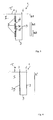
FIG. 1 schematically shows a first embodiment of a sensor according to the invention; and -
FIG. 2 schematically shows an implant comprising a sensor according to a first embodiment of the invention. -
FIG. 3 schematically shows an implant comprising the sensor according to a second embodiment of the invention; and -
FIG. 4 schematically shows an implant comprising a sensor according to a third embodiment of the invention. - It is noted that similar parts in the different figures are referred to by similar reference numerals.
- In
Figure 1 animplantable sensor 1 according to the invention is shown. Thesensor 1 comprises abody 2. Thebody 2 can be of an electrically insulating material such as a biodegradable polymer. Preferably, the biodegradable material of thebody 2 is a biodegradable polymer, for instance one of poly-1-lactic acid (PLLA), polyglycolic acid (PGA), poly-D,L-lactide.glycolide copolymer (PDLA), polyaprolactine (PCL) or the like. Thebody 2 substantially encapsulates theelectrical circuit 3. Thebody 2 further comprises a receivingsection 4 wherein amonitoring element 5 is provided. Thebody 2 can be of two polymer sheets where in between theelectrical circuit 3 and themonitoring element 5 are provided. Themonitoring element 5 is of the same material as the material of the implant (not shown) and thus comprises a similar corrosion resistance. Thecircuit wire 9 is of a material having a corrosion resistance that is higher than that of the implant material. The ends of thecircuit wire 9, which ends define electrical nodes (6, 7) are in contact with the tissue (T) surrounding the implant and thesensor 1. Thecircuit wire 9 and themonitoring element 5 both comprise a biodegradable metal or metal alloy, such as magnesium, iron, magnesium alloys and/or iron alloys with Al, Ca, F, Fe, Li, Mg, Mn, rare earth elements, Zn, Zr or the like or any combination thereof. - The
circuit wire 9 comprises one or more (here three as an example)resistance elements 3a, 3b, 3c that are spaced apart and all are connected in parallel to thecircuit wire 9 with a first end and connected to themonitoring element 5 with a second end. Thecircuit wire 9 and theresistance elements 3a, 3b, 3c preferably have a similar corrosion rate. Themonitoring element 5 together with theresistance elements 3a, 3b, 3c and thecircuit wire 9 form theelectrical circuit 3. - The
sensor 1 can be connected to an implant before or after it is implanted in the body. Thesensor 1 can also be embedded in the implant I (seeFig. 2 ). When thesensor 1 is connected to an implant I, thesensor 1 will not be able to drift easily in the patient's body. Furthermore, since themonitoring element 5 is provided close to the implant I, themonitoring element 5 will be exposed to substantially the same physiological environment as the implant, which further increases the accuracy of the measurements taken by thesensor 1. - For determining for instance the corrosion rate of the implant I, the corrosion rate of the
monitoring element 5 is monitored. In use, thus in-vivo, themonitoring element 5 corrodes due to the contact with the physiological environment of the implant. Consequently, thefirst end 5a of themonitoring element 5 will degrade, thereby decreasing the total length of themonitoring element 5. In other words, material of themonitoring element 5 on theside 5a that is facing away from thebody 2 will degrade first. - When a voltage difference is applied, a current will be generated in the
electrical circuit 3. The magnitude of the generated current can be determined outside the patient's body for instance by using an electromagnetic field detector. It is also possible to extend thenodes electrical circuit 3 can be calculated as explained later. - When a certain amount of material (represented by arrow a) of the
monitoring element 5 has degraded, the first resistance element 3a will disconnect frommonitoring element 5. Since theelectrical circuit 3 forms a switch on/off type of circuit, the equivalent resistance of theelectrical circuit 3 can only have certain values. Assuming that theelectrical circuit 3 comprises threeidentical resistance elements 3a, 3b, 3c having resistance R in parallel, the initial resistance R°, at a certain reference temperature is determined by:
- If the
resistance elements 3a, 3b, 3c are consecutively disconnected from thecircuit 3, the instantaneous equivalent resistance R' of thecircuit 3 can have the following values:
when threeresistance elements 3a, 3b, 3c are still connected to themonitoring element 5;
when one resistance element 3a is disconnected (thus themonitoring element 5 has degraded over length a) and tworesistance elements 3b, 3c are still connected;
when tworesistance elements 3a, 3b are disconnected (thus themonitoring element 5 has degraded over length a+b) and one resistance element 3c is still connected; and
when none of theresistance elements 3a, 3b, 3c is connected to themonitoring element 5 since themonitoring element 5 has degraded over length a+b+c. - Calibration of the
sensor 1 needs to be done before the implantation by laboratory tests. An empirical correlation between the corrosion rate of the implant I and the corrosion rate measured by thesensor 1 can be derived experimentally. - The initial number of
resistance elements 3a, 3b, 3c comprised in the electrical circuit determines the accuracy of corrosion rate measurement. However, there is an optimum number regarding for instance space limitations and the fact that a high number ofresistance elements - Inflammation around an implant can be detected by monitoring the local temperature of tissue T. The local temperature can be detected by the
sensor 1 according to the invention, as follows. As explained above, at a certain temperature Tref (normal in-vivo temperature), R' can have only certain values. Deviation from these values indicates a temperature related shift in the equivalent resistance, given by the following relationship:
wherein a is the average temperature coefficient of resistance in a certain temperature range. To be able to measure the temperature difference, the resistance change caused by the temperature difference should be less than the resistance change caused by the disconnection of theindividual resistance elements 
wherein n is the number of resistance elements. This range becomes smaller as the number of resistance elements increases. - The
sensor 1 can be attached to an implant I after the implant I is placed in a patient's body. In this way, more working space around the implant I is created for the surgeon, without the sensor being in the way. However, thesensor 1 can already be connected to the implant I for instance during the manufacturing process, or can be embedded in the implant I as can be seen inFigure 2 . - In
Figure 2 an implant I, in this case a bone screw, comprising asensor 1 as above described is schematically shown. Thesensor 1 is completely embedded in the bone screw. Theelectrical nodes electrical circuit 3, and also thefirst end 5a of themonitoring element 5 of the implant material extend from the outer surface of the bone screw in a direction away from the implant I into the tissue T surrounding the implant I. In use, theelectrical nodes first end 5a of themonitoring element 5 are in contact with human tissue T surrounding the implant I. The working principles of this second embodiment of thesensor 1 according to the invention are the same as explained inFigure 1 and therefore will not be explained again. -
Figure 3 shows an implant I comprising asensor 1 according to a second embodiment of the invention. Thesensor 1 is integrated with the implant I. Theelectrical circuit 3 comprises resistance elements 3d, 3e, 3f in series with thecircuit wire 9. The separate resistance elements 3d, 3e, 3f, are encapsulated by insulating material 8, at least by a material that is an electrical insulator at the voltages used to activate thesensor 1. The insulating material 8 has a similar corrosion rate as the implant material. Due to this construction of thesensor 1, the metallic implant I can not short circuit thesensor 1. The material of thesensor 1 degrades at the same rate as the material of the implant I. The insulating material 8 can be of a biodegradable polymer, hydroxyapatite (HA) or a bio-compatible powder or gel or the like. The resistance elements 3d, 3e, 3f are connected in series in theelectrical circuit 3. Thecircuit wire 9 has a higher corrosion resistance rate than the other parts of thesensor 1. Since the resistance elements 3d, 3e, 3f will corrode at the same rate as the implant I, an extra monitoring element of the implant material will not be needed. In this embodiment of thesensor 1, the current is applied to the electrical circuit in the same way as mentioned before. The total resistance of thesensor 1 to be measured a time t=0 is:
- The remaining life of the implant I can be calculated as follows:

wherein 3R represents the implant length h1 being intact, 2R represents h2 being intact, R represents h3 being intact and 0 represents that length h1 has corroded. - In
Figure 4 , a further embodiment of thesensor 1 according to the invention is shown. In this embodiment thesensor 1 is again completely embedded in the implant I. A single resistance element 3g is placed in theelectrical circuit 3. The resistance element 3g and thecircuit wire 9 of theelectrical circuit 3 have a significantly higher corrosion resistance than the implant material. In this embodiment, neither a monitoring element nor an insulating material is necessary, which is advantageous regarding ease in manufacturing. Thesensor 1 works as follows. When the implant I is intact, the measured resistance is minimum, since the metallic implant I short-circuits the resistance element 3g. After being exposed to a corrosive medium, i.e. the tissue T surrounding the implant I, the implant I will corrode in time. As corrosion advances, non-conductive corrosion product will surround theelectrical circuit 3, thereby increasing the measured resistance when a current is applied to theelectrical circuit 3. The current is applied in the same way as mentioned before. The long resistance 3g perpendicular to theimplant surface 10 will ensure that the implant I is acting as a rheostat. Such asensor 1 provides a more accurate measurement of the advancement of corrosion. If the original resistance is R° spanning a length of h°, and the measured resistance is R, the corroded implant length is represented by:
- The
sensor 1 integrated in the implant I according to the second and third embodiment of the invention (seeFig. 3 and Fig. 4 ), has a further advantage such that due to the direct sensing from the implant, calibration of the sensor is not necessary. Because of the relativelylarge implant surface 10, the local pH around the implant is almost instantly at equilibrium with its surroundings. However, the corrosion products at the monitoring element are confined to a narrow space and the chemical equilibrium is dependent on the diffusion rate. - The invention is not in any way limited to the exemplary embodiments presented in the description and drawings. All combinations (of parts) of the embodiments shown and described are explicitly understood to fall within the scope of the invention. Moreover, many variations are possible within the scope of the invention, as outlined by the claims.
Claims (16)
- An implantable sensor adapted for monitoring a condition of an in-vivo implant (I) or of tissue (T) surrounding said implant (I), wherein the sensor (1) comprises means for monitoring said condition, the means comprising an electrical circuit (3) with at least one resistance element (3a-3g), the electrical circuit (3) in use being in contact with implant material and adapted to carry a current generated by a voltage difference applied to the electrical circuit, wherein the condition can be determined by measuring said current and calculating an equivalent resistance of the electrical circuit based on said measured current.
- An implantable sensor according to claim 1, wherein at least one end of the electrical circuit (3), which at least one end defines an electrical node (6, 7), is adapted to be in use in contact with the tissue (T) surrounding the implant (I).
- An implantable sensor according to any one of the preceding claims wherein the sensor (1) is a biodegradable sensor.
- An implantable sensor according to any one of the preceding claims, wherein the electrical circuit (3) has a higher corrosion resistance than the implant material.
- An implantable sensor according to any one of the preceding claims, wherein the sensor (1) comprises an insulating body (2) that substantially encapsulates the electrical circuit (3), wherein the ends of the electrical circuit (3) extend from the insulating body (2), wherein the insulating body (2) has a higher corrosion resistance than the implant material.
- An implantable sensor according to claim 5, wherein the insulating body (2) comprises a receiving section (4) for receiving a monitoring element (5) of the implant material.
- An implantable sensor according to claim 5 or 6, wherein the electrical circuit (3) comprises a plurality of resistance elements (3a, 3b, 3c) that are spaced apart and which are connected in parallel to the electrical circuit (3), at least to a circuit wire(9) of the electrical circuit (3), with a first end and to the implant material with a second end, wherein the electrical circuit (3) and the resistance elements (3a, 3b, 3c) preferably have a substantially similar corrosion resistance.
- An implantable sensor according to any one of claims 1-4, wherein the electrical circuit (3) comprises a plurality of resistance elements (3d, 3e, 3f) in series, wherein the resistance elements (3d, 3e, 3f) are encapsulated in an insulating material (8), wherein the resistance elements (3d. 3e, 3f), the insulating material (8) and the implant (I) preferably have a substantially similar corrosion resistance which is lower than a corrosion resistance of a circuit wire (9) of the electrical circuit (3).
- An implantable sensor according to any one of claims 1-4, wherein the electrical circuit (3) comprises a resistance element (3g), wherein the electrical circuit (3) and the resistance element (3g) have a substantially higher corrosion resistance rate than the implant.
- A sensor assembly comprising a sensor according to any one of claims 5-7 and a monitoring element (5) of the implant material, wherein the monitoring element (5) is connected to the electrical circuit (3) and wherein a first end (5a) of the monitoring element (5) extends from the insulating body (2) and is adapted for contacting the tissue (T) surrounding the implant (I).
- An implant comprising a sensor according to any one of claims 1-9 or a sensor assembly according to claim 10, wherein the electrical nodes (6, 7) extend from the implant (I), wherein the implant (I) contacting the electrical circuit (3) is adapted to in use contact the tissue (T) surrounding said implant (I).
- An implant according to claim 11, wherein the implant (I) is made of a biodegradable material.
- A method for monitoring a condition of an in-vivo implant or of tissue surrounding said implant, wherein the method comprises the steps of:- implanting an implant (I) and a sensor (3) according to any one of claims 1-9 or a sensor assembly according to claim 10 into a body of a patient;- applying a voltage difference to excite the electrical circuit of the sensor (1) to generate a current;- measuring the current;- calculating the equivalent resistance of the electrical circuit based on said measured current- determining the condition based on the calculated equivalent resistance
- A method according to claim 13, wherein the condition is a rate of corrosion of the implant (I) and/or occurrence of inflammation of the tissue (T) surrounding the implant (I).
- A method according to claim 13 or 14, wherein the current is measured wireless from outside the patient's body, for instance by an electromagnetic field detector.
- A method according to claim 13 or 14, wherein the current is measured wired from a patient's skin, for instance by biocompatible and/or biodegradable wires extending from the sensor (1) to the skin.
Priority Applications (2)
| Application Number | Priority Date | Filing Date | Title |
|---|---|---|---|
| EP08157210A EP2127596A1 (en) | 2008-05-29 | 2008-05-29 | Implantable sensor, sensor assembly comprising such a sensor, implant comprising such an implantable sensor or sensor assembly and method of monitoring a condition of an in-vivo implant or of tissue surrounding said implant |
| PCT/NL2009/050300 WO2009145633A1 (en) | 2008-05-29 | 2009-05-29 | Implantable sensor, sensor assembly comprising such a sensor, implant comprising such an implantable sensor or sensor assembly and method of monitoring a condition of an in-vivo implant or of tissue surrounding said implant |
Applications Claiming Priority (1)
| Application Number | Priority Date | Filing Date | Title |
|---|---|---|---|
| EP08157210A EP2127596A1 (en) | 2008-05-29 | 2008-05-29 | Implantable sensor, sensor assembly comprising such a sensor, implant comprising such an implantable sensor or sensor assembly and method of monitoring a condition of an in-vivo implant or of tissue surrounding said implant |
Publications (1)
| Publication Number | Publication Date |
|---|---|
| EP2127596A1 true EP2127596A1 (en) | 2009-12-02 |
Family
ID=39798261
Family Applications (1)
| Application Number | Title | Priority Date | Filing Date |
|---|---|---|---|
| EP08157210A Withdrawn EP2127596A1 (en) | 2008-05-29 | 2008-05-29 | Implantable sensor, sensor assembly comprising such a sensor, implant comprising such an implantable sensor or sensor assembly and method of monitoring a condition of an in-vivo implant or of tissue surrounding said implant |
Country Status (2)
| Country | Link |
|---|---|
| EP (1) | EP2127596A1 (en) |
| WO (1) | WO2009145633A1 (en) |
Cited By (2)
| Publication number | Priority date | Publication date | Assignee | Title |
|---|---|---|---|---|
| WO2013021357A1 (en) | 2011-08-08 | 2013-02-14 | Ecole Polytechnique Federale De Lausanne (Epfl) | In-vivo condition monitoring of metallic implants by electrochemical techniques |
| WO2014145491A1 (en) * | 2013-03-15 | 2014-09-18 | Syracuse University | Smart medical device for electrochemical monitoring and control of medical implants |
Families Citing this family (6)
| Publication number | Priority date | Publication date | Assignee | Title |
|---|---|---|---|---|
| CN112168143A (en) | 2013-03-15 | 2021-01-05 | 威廉·L·亨特 | Devices, systems, and methods for monitoring hip replacements |
| EP3013283B8 (en) | 2013-06-23 | 2021-03-03 | Canary Medical Inc. | Devices, systems and methods for monitoring knee replacements |
| WO2016044651A1 (en) | 2014-09-17 | 2016-03-24 | Canary Medical Inc. | Devices, systems and methods for using and monitoring medical devices |
| IL294630B2 (en) | 2016-03-23 | 2023-12-01 | Canary Medical Inc | An implantable report processor for an alert implant |
| CA3176873A1 (en) | 2019-06-06 | 2020-12-10 | Canary Medical Inc. | Intelligent joint prosthesis |
| US20210366610A1 (en) | 2019-06-06 | 2021-11-25 | Canary Medical Inc. | Intelligent joint prosthesis |
Citations (5)
| Publication number | Priority date | Publication date | Assignee | Title |
|---|---|---|---|---|
| EP0344770A1 (en) * | 1988-06-01 | 1989-12-06 | State Of Israel-Ministry Of Agriculture | Device for telemetering living tissue impedance by radio means |
| EP1177811A1 (en) * | 2000-03-06 | 2002-02-06 | Terumo Kabushiki Kaisha | Living body insertion electrode lead, and living body insertion medical instrument using the same |
| US20030199783A1 (en) * | 2002-04-17 | 2003-10-23 | Matthew Bloom | User-retainable temperature and impedance monitoring methods and devices |
| US6901294B1 (en) * | 2001-05-25 | 2005-05-31 | Advanced Bionics Corporation | Methods and systems for direct electrical current stimulation as a therapy for prostatic hypertrophy |
| WO2007090159A1 (en) * | 2006-01-31 | 2007-08-09 | Medtronic, Inc. | Implantable sensor |
-
2008
- 2008-05-29 EP EP08157210A patent/EP2127596A1/en not_active Withdrawn
-
2009
- 2009-05-29 WO PCT/NL2009/050300 patent/WO2009145633A1/en not_active Ceased
Patent Citations (5)
| Publication number | Priority date | Publication date | Assignee | Title |
|---|---|---|---|---|
| EP0344770A1 (en) * | 1988-06-01 | 1989-12-06 | State Of Israel-Ministry Of Agriculture | Device for telemetering living tissue impedance by radio means |
| EP1177811A1 (en) * | 2000-03-06 | 2002-02-06 | Terumo Kabushiki Kaisha | Living body insertion electrode lead, and living body insertion medical instrument using the same |
| US6901294B1 (en) * | 2001-05-25 | 2005-05-31 | Advanced Bionics Corporation | Methods and systems for direct electrical current stimulation as a therapy for prostatic hypertrophy |
| US20030199783A1 (en) * | 2002-04-17 | 2003-10-23 | Matthew Bloom | User-retainable temperature and impedance monitoring methods and devices |
| WO2007090159A1 (en) * | 2006-01-31 | 2007-08-09 | Medtronic, Inc. | Implantable sensor |
Cited By (2)
| Publication number | Priority date | Publication date | Assignee | Title |
|---|---|---|---|---|
| WO2013021357A1 (en) | 2011-08-08 | 2013-02-14 | Ecole Polytechnique Federale De Lausanne (Epfl) | In-vivo condition monitoring of metallic implants by electrochemical techniques |
| WO2014145491A1 (en) * | 2013-03-15 | 2014-09-18 | Syracuse University | Smart medical device for electrochemical monitoring and control of medical implants |
Also Published As
| Publication number | Publication date |
|---|---|
| WO2009145633A1 (en) | 2009-12-03 |
Similar Documents
| Publication | Publication Date | Title |
|---|---|---|
| WO2009145633A1 (en) | Implantable sensor, sensor assembly comprising such a sensor, implant comprising such an implantable sensor or sensor assembly and method of monitoring a condition of an in-vivo implant or of tissue surrounding said implant | |
| US7182736B2 (en) | Apparatus and method for assessing loads on adjacent bones | |
| EP3135186B1 (en) | Implantable sensor | |
| JP4959146B2 (en) | Joint endoprosthesis with environmental condition detection | |
| US8442620B2 (en) | Implantable lead/electrode delivery measurement and feedback system | |
| US7989703B2 (en) | Alternating core composite wire | |
| US20140379090A1 (en) | In-vivo condition monitoring of metallic implants by electrochemical techniques | |
| CN114126481A (en) | Temperature sensing array for set screw infection | |
| AU2001288417A1 (en) | Apparatus and method for assessing loads on adjacent bones | |
| Ramakrishna et al. | Smart orthopaedic implants: A targeted approach for continuous postoperative evaluation in the spine | |
| KR20150024235A (en) | Medical inserting apparatus | |
| US20170202691A1 (en) | Sensor-stents | |
| US20190328315A1 (en) | Internal anatomical force measurement | |
| US7878988B2 (en) | Method for measuring the strength of healing bone and related tissues | |
| EP3322354B1 (en) | System for monitoring a surgical site | |
| WO2009055865A1 (en) | Implantable prosthesis with sensor | |
| EP1804647A1 (en) | Microsensor system for applications in biomechanics | |
| EP4399499B1 (en) | Device for detecting a working status of a medical implant | |
| Umezawa et al. | Development of a Shape Memory Nitinol Tracheal Stent for Veterinary Medicine | |
| Hudak et al. | Effect of the fixation patterns on magnetic characteristics of amorphous glass-coated sensoric microwires | |
| KR20260046171A (en) | Detection method, detection device, diagnostic device and program | |
| CZ24304U1 (en) | Device to determine stability of bone implant | |
| Ramakrishna et al. | Smart orthopaedic implants: A targeted approach for continuous postoperative evaluation in the |
Legal Events
| Date | Code | Title | Description |
|---|---|---|---|
| PUAI | Public reference made under article 153(3) epc to a published international application that has entered the european phase |
Free format text: ORIGINAL CODE: 0009012 |
|
| AK | Designated contracting states |
Kind code of ref document: A1 Designated state(s): AT BE BG CH CY CZ DE DK EE ES FI FR GB GR HR HU IE IS IT LI LT LU LV MC MT NL NO PL PT RO SE SI SK TR |
|
| AX | Request for extension of the european patent |
Extension state: AL BA MK RS |
|
| AKY | No designation fees paid | ||
| REG | Reference to a national code |
Ref country code: DE Ref legal event code: 8566 |
|
| STAA | Information on the status of an ep patent application or granted ep patent |
Free format text: STATUS: THE APPLICATION IS DEEMED TO BE WITHDRAWN |
|
| 18D | Application deemed to be withdrawn |
Effective date: 20100603 |