EP2127003B1 - Method of preconditioning a lithium/iron-disulfide cell - Google Patents
Method of preconditioning a lithium/iron-disulfide cell Download PDFInfo
- Publication number
- EP2127003B1 EP2127003B1 EP08719770A EP08719770A EP2127003B1 EP 2127003 B1 EP2127003 B1 EP 2127003B1 EP 08719770 A EP08719770 A EP 08719770A EP 08719770 A EP08719770 A EP 08719770A EP 2127003 B1 EP2127003 B1 EP 2127003B1
- Authority
- EP
- European Patent Office
- Prior art keywords
- cell
- cathode
- lithium
- electrolyte
- fes
- Prior art date
- Legal status (The legal status is an assumption and is not a legal conclusion. Google has not performed a legal analysis and makes no representation as to the accuracy of the status listed.)
- Not-in-force
Links
Images




Classifications
-
- H—ELECTRICITY
- H01—ELECTRIC ELEMENTS
- H01M—PROCESSES OR MEANS, e.g. BATTERIES, FOR THE DIRECT CONVERSION OF CHEMICAL ENERGY INTO ELECTRICAL ENERGY
- H01M6/00—Primary cells; Manufacture thereof
- H01M6/50—Methods or arrangements for servicing or maintenance, e.g. for maintaining operating temperature
-
- H—ELECTRICITY
- H01—ELECTRIC ELEMENTS
- H01M—PROCESSES OR MEANS, e.g. BATTERIES, FOR THE DIRECT CONVERSION OF CHEMICAL ENERGY INTO ELECTRICAL ENERGY
- H01M4/00—Electrodes
- H01M4/02—Electrodes composed of, or comprising, active material
- H01M4/36—Selection of substances as active materials, active masses, active liquids
- H01M4/38—Selection of substances as active materials, active masses, active liquids of elements or alloys
- H01M4/381—Alkaline or alkaline earth metals elements
- H01M4/382—Lithium
-
- H—ELECTRICITY
- H01—ELECTRIC ELEMENTS
- H01M—PROCESSES OR MEANS, e.g. BATTERIES, FOR THE DIRECT CONVERSION OF CHEMICAL ENERGY INTO ELECTRICAL ENERGY
- H01M4/00—Electrodes
- H01M4/02—Electrodes composed of, or comprising, active material
- H01M4/36—Selection of substances as active materials, active masses, active liquids
- H01M4/58—Selection of substances as active materials, active masses, active liquids of inorganic compounds other than oxides or hydroxides, e.g. sulfides, selenides, tellurides, halogenides or LiCoFy; of polyanionic structures, e.g. phosphates, silicates or borates
- H01M4/581—Chalcogenides or intercalation compounds thereof
- H01M4/5815—Sulfides
-
- H—ELECTRICITY
- H01—ELECTRIC ELEMENTS
- H01M—PROCESSES OR MEANS, e.g. BATTERIES, FOR THE DIRECT CONVERSION OF CHEMICAL ENERGY INTO ELECTRICAL ENERGY
- H01M6/00—Primary cells; Manufacture thereof
- H01M6/14—Cells with non-aqueous electrolyte
- H01M6/16—Cells with non-aqueous electrolyte with organic electrolyte
- H01M6/162—Cells with non-aqueous electrolyte with organic electrolyte characterised by the electrolyte
- H01M6/164—Cells with non-aqueous electrolyte with organic electrolyte characterised by the electrolyte by the solvent
-
- H—ELECTRICITY
- H01—ELECTRIC ELEMENTS
- H01M—PROCESSES OR MEANS, e.g. BATTERIES, FOR THE DIRECT CONVERSION OF CHEMICAL ENERGY INTO ELECTRICAL ENERGY
- H01M6/00—Primary cells; Manufacture thereof
- H01M6/50—Methods or arrangements for servicing or maintenance, e.g. for maintaining operating temperature
- H01M6/5088—Initial activation; predischarge; Stabilisation of initial voltage
-
- H—ELECTRICITY
- H01—ELECTRIC ELEMENTS
- H01M—PROCESSES OR MEANS, e.g. BATTERIES, FOR THE DIRECT CONVERSION OF CHEMICAL ENERGY INTO ELECTRICAL ENERGY
- H01M6/00—Primary cells; Manufacture thereof
- H01M6/14—Cells with non-aqueous electrolyte
- H01M6/16—Cells with non-aqueous electrolyte with organic electrolyte
- H01M6/162—Cells with non-aqueous electrolyte with organic electrolyte characterised by the electrolyte
- H01M6/166—Cells with non-aqueous electrolyte with organic electrolyte characterised by the electrolyte by the solute
-
- H—ELECTRICITY
- H01—ELECTRIC ELEMENTS
- H01M—PROCESSES OR MEANS, e.g. BATTERIES, FOR THE DIRECT CONVERSION OF CHEMICAL ENERGY INTO ELECTRICAL ENERGY
- H01M6/00—Primary cells; Manufacture thereof
- H01M6/14—Cells with non-aqueous electrolyte
- H01M6/16—Cells with non-aqueous electrolyte with organic electrolyte
- H01M6/162—Cells with non-aqueous electrolyte with organic electrolyte characterised by the electrolyte
- H01M6/168—Cells with non-aqueous electrolyte with organic electrolyte characterised by the electrolyte by additives
-
- Y—GENERAL TAGGING OF NEW TECHNOLOGICAL DEVELOPMENTS; GENERAL TAGGING OF CROSS-SECTIONAL TECHNOLOGIES SPANNING OVER SEVERAL SECTIONS OF THE IPC; TECHNICAL SUBJECTS COVERED BY FORMER USPC CROSS-REFERENCE ART COLLECTIONS [XRACs] AND DIGESTS
- Y02—TECHNOLOGIES OR APPLICATIONS FOR MITIGATION OR ADAPTATION AGAINST CLIMATE CHANGE
- Y02E—REDUCTION OF GREENHOUSE GAS [GHG] EMISSIONS, RELATED TO ENERGY GENERATION, TRANSMISSION OR DISTRIBUTION
- Y02E60/00—Enabling technologies; Technologies with a potential or indirect contribution to GHG emissions mitigation
- Y02E60/10—Energy storage using batteries
Definitions
- the invention relates to a method for preconditioning a primary cell having an anode comprising lithium and a cathode comprising iron disulfide.
- a fresh cell is subjected to a pulsed discharge step followed by step rest at elevated temperature, preferably followed by a second pulsed discharge step, thereby preconditioning the cell and improving cell performance.
- Primary (non-rechargeable) electrochemical cells having an anode of lithium are known and are in widespread commercial use.
- the anode is comprised essentially of lithium metal.
- Such cells typically have a cathode comprising manganese dioxide, and electrolyte comprising a lithium salt such as lithium trifluoromethane sulfonate (LiCF 3 SO 3 ) dissolved in a nonaqueous solvent.
- the cells are referenced in the art as primary lithium cells (primary Li/MnO 2 cells) and are generally not intended to be rechargeable, that is, they are intended to be discarded after they have been discharged.
- Alternative primary lithium cells with lithium metal anodes but having different cathodes are also known.
- Such cells have cathodes comprising iron disulfide (FeS 2 ) and are designated Li/FeS 2 cells.
- the iron disulfide (FeS 2 ) is also known as pyrite.
- the Li/MnO 2 cells or Li/FeS 2 cells are typically in the form of cylindrical cells, typically an AA size cell or 2/3A Li/MnO 2 cell.
- the Li/MnO 2 cells have a voltage of about 3.0 volts which is twice that of conventional Zn/MnO 2 alkaline cells and also have higher energy density (watt-hrs per cm 3 of cell volume) than that of alkaline cells.
- the Li/FeS 2 cells have a voltage (fresh) of between about 1.2 and 1.5 volts which is about the same as a conventional Zn/MnO 2 alkaline cell.
- the energy density (watt-hrs per cm 3 of cell volume) of the Li/FeS 2 cell is also much higher than a comparable size Zn/MnO 2 alkaline cell.
- the theoretical specific capacity of lithium metal is high at 3861.7 mAmp-hr/gram and the theoretical specific capacity of FeS 2 is 893.6 mAmp-hr/gram.
- the FeS 2 theoretical capacity is based on a 4 electron transfer from 4Li per FeS 2 to result in reaction product of elemental iron Fe and 2Li 2 S. That is, 2 of the 4 electrons reducing the valence state of Fe +2 in FeS 2 to Fe and the remaining 2 electrons reducing the valence of sulfur from -1 in FeS 2 to -2 in Li 2 S.
- Li/FeS 2 cell is much more powerful than the same size Zn/MnO 2 alkaline cell. That is for a given continuous current drain, particularly for higher current drain over 200 milliAmp, in the voltage vs. time profile the voltage drops off much less quickly for the Li/FeS 2 cell than the Zn/MnO 2 alkaline cell. This results in a higher energy obtainable from a Li/FeS 2 cell compared to that obtainable for a same size alkaline cell.
- the higher energy output of the Li/FeS 2 cell is also clearly shown more directly in graphical plots of energy (Watt-hrs) versus continuous discharge at constant power (Watts) wherein fresh cells are discharged to completion at fixed continuous power outputs ranging from as little as 0.01 Watt to 5 Watt. In such tests the power drain is maintained at a constant continuous power output selected between 0.01 Watt and 5 Watt. (As the cell's voltage drops during discharge the load resistance is gradually decreased raising the current drain to maintain a fixed constant power output.)
- the graphical plot Energy (Watt-Hrs) versus Power Output (Watt) for the Li/FeS 2 cell is considerably above that for the same size alkaline cell. This is despite that the starting voltage of both cells (fresh) is about the same, namely, between about 1.2 and 1.5 volt.
- the Li/FeS 2 cell has the advantage over same size alkaline cells, for example, AAA, AA, C or D size or any other size cell in that the Li/FeS 2 cell may be used interchangeably with the conventional Zn/MnO 2 alkaline cell and will have greater service life, particularly for higher power demands.
- the Li/FeS 2 cell which is primary (nonrechargeable) cell can be used as a replacement for the same size rechargeable nickel metal hydride cells, which have about the same voltage (fresh) as the Li/FeS 2 cell.
- the cathode material may be initially prepared in a form such as a slurry mixture, which can be readily coated onto the metal substrate by conventional coating methods.
- the electrolyte added to the cell must be a suitable nonaqueous electrolyte for the Li/FeS 2 system allowing the necessary electrochemical reactions to occur efficiently over the range of high power output desired.
- the electrolyte must exhibit good ionic conductivity and also be sufficiently stable to the undischarged electrode materials (anode and cathode) and to the resulting discharge products. This is because undesirable oxidation/reduction reactions between the electrolyte and electrode materials (either discharged or undischarged) could thereby gradually contaminate the electrolyte and reduce its effectiveness or result in excessive gassing. This in turn can result in a catastrophic cell failure.
- the electrolyte used in Li/FeS 2 cell in addition to promoting the necessary electrochemical reactions, should also be stable to discharged and undischarged electrode materials.
- Primary lithium cells are in use as a power source for digital flash cameras, which require operation at higher power demands than is supplied by individual alkaline cells.
- Primary lithium cells are conventionally formed of an electrode composite comprising an anode formed of a sheet of lithium, a cathode formed of a coating of cathode active material comprising FeS 2 on a conductive metal substrate (cathode substrate) and a sheet of electrolyte permeable separator material therebetween.
- the electrode composite may be spirally wound and inserted into the cell casing, for examples, as shown in U.S. patent 4,707,421 .
- a cathode coating mixture for the Li/FeS 2 cell is described in U.S. 6,849,360 .
- a portion of the anode sheet is typically electrically connected to the cell casing which forms the cell's negative terminal.
- the cell is closed with an end cap which is insulated from the casing.
- the cathode sheet can be electrically connected to the end cap which forms the cell's positive terminal.
- the casing is typically crimped over the peripheral edge of the end cap to seal the casing's open end.
- the anode in a Li/FeS 2 cell can be formed by laminating a layer of lithium on a metallic substrate such as copper.
- the anode may be formed of a sheet of lithium without any substrate.
- the electrolyte used in a primary Li/FeS 2 cells is a non aqueous organic electrolyte formed typically of a "lithium salt” dissolved in an "organic solvent".
- An "organic electrolyte” includes, but is not limited to, an electrolyte comprising a lithium salt (or other salt) dissolved in an organic solvent. Representative lithium salts which may be used in electrolytes for Li/FeS 2 primary cells are referenced in U.S. patents 5,290,414 and U.S.
- Lithium trifluoroinethanesulfonate LiCF 3 SO 3 (LiTFS); lithium bistrifluoromethylsulfonyl imide, Li(CF 3 SO 2 ) 2 N (LiTFSI); lithium iodide, LiI; lithium bronide, LiBr; lithium tetrafluoroborate, LiBF 4 ; lithium hexafluorophosphate, LiPF 6 ; lithium hexafluoroarsenate, LiAsF 6 ; Li(CF 3 SO 2 ) 3 C, and various mixtures.
- LiTFS Lithium trifluoroinethanesulfonate
- Li(CF 3 SO 2 ) 2 N LiTFSI
- LiI lithium bistrifluoromethylsulfonyl imide
- Li(CF 3 SO 2 ) 2 N LiTFSI
- lithium iodide LiI
- LiBr lithium tetrafluoroborate
- LiBF 4 lithium hexafluorophosphate
- organic solvents which are referenced in the art for possible use in connection with organic solvents for electrolytes for primary Li/FeS 2 cells are as follows: propylene carbonate (PC), ethylene carbonate (EC), butylene carbonate (BC), dimethoxyethane (DME), ethyl glyme, diglyme and triglyme, dimethoxypropane (DMP), dioxolane (DIOX), 3,5-dimethlyisoxazole (DMI), tetrahydrofuran (THF), diethyl carbonate (DEC), ethylene glycol sulfite (EGS), dioxane, dimethylsulfate (DMS), 3-methyl-2-oxazolidone, and sulfolane (SU), and various mixtures.
- PC propylene carbonate
- EC ethylene carbonate
- BC butylene carbonate
- DME dimethoxyethane
- DME dimethoxypropane
- DMP dio
- a beneficial electrolyte for FeS 2 cells wherein the electrolyte comprises a lithium salt dissolved in a solvent comprising dioxolane in admixture with an acyclic (non cyclic) ether based solvent.
- the acyclic (non cyclic) ether based solvent as referenced may be dimethoxyethane, ethyl glyme, diglyme and triglyme, with the preferred being 1-2 dimetoxyehtane(DME).
- a specific lithium salt ionizable in such solvent mixture(s) is given as LiCF 3 SO 3 (LiTFS) or Li(CF 3 SO 2 ) 2 N (LiTFSI), or mixtures thereof.
- a cosolvent selected from 3,5-dimethlyisoxazole (DMI), 3-methyl-2-oxazolidone, propylene carbonate (PC), ethylene carbonate (EC), butylene carbonate (BC), and sulfolane.
- U.S. 6,849,360 B2 is specifically disclosed an electrolyte for an Li/FeS 2 cell, wherein the electrolyte comprises the salt lithium iodide dissolved in the organic solvent mixture comprising 1,3-dioxolane (DIOX), 1,2-dimethoxyethane (DME), and small amount of 3,5 dimethylisoxazole (DMI).
- DIOX 1,3-dioxolane
- DME 1,2-dimethoxyethane
- DMI 3,5 dimethylisoxazole
- dioxolane has the disadvantage of cost and handling.
- solvents for the Li/FeS 2 cell electrolyte which are more cost effective and easier to handle than dioxolane.
- solvents can be selected from cyclic organic carbonates, for example, ethylene carbonate (EC) and propylene carbonate (PC), which are less expensive and easier to store and handle than dioxolane.
- Ethylene carbonate (EC) and propylene carbonate (PC) alone or in admixture and also in admixture with dimethoxyethane (DME) have produced very suitable solvents for electrolytes for use in connection with Li/MnO 2 cells, particularly when the lithium salt for the electrolyte comprises LiCF 3 SO 3 (LITFS).
- LITFS LiCF 3 SO 3
- An insoluble layer is gradually formed on the lithium metal surface, which tends to passivate the lithium metal surface, making it less reactive.
- Such surface layers some more debilitating than others, can reduce the rate of the electrochemical reaction involving the lithium anode metal during cell discharge, thus interfering with proper cell performance.
- Li/FeS 2 cell employing a cost effective electrolyte but which cell nevertheless exhibits reduced or suppressed rate of lithium anode passivation.
- Li/FeS 2 cell which exhibits reduced voltage delay (voltage drop) occurring at the onset of any new discharge period.
- the electrolyte comprises a cyclic organic carbonate solvent, in particular a cyclic glycol carbonate desirably such as, but not limited to, ethylene carbonate, propylene carbonate, butylene carbonate, and mixtures thereof.
- a cyclic glycol carbonate desirably such as, but not limited to, ethylene carbonate, propylene carbonate, butylene carbonate, and mixtures thereof.
- electrolyte for a Li/FeS 2 cell wherein the electrolyte comprises a solvent which is free of dioxolane.
- the invention concerns lithium primary cells wherein the anode comprises lithium metal.
- the lithium may be alloyed with small amounts of an alloy metal, for example aluminum, forming a lithium alloy, which typically comprises less than about 1 wt.% of the alloy metal.
- the lithium which forms the anode active material is preferably in the form of a thin foil.
- the cell has a cathode comprising the cathode active material iron disulfide (FeS 2 ), commonly known as "pyrite".
- FeS 2 iron disulfide
- the Li/FeS 2 cell may be in the form of a button (coin) cell or flat cell. Desirably the cell may be in the form of a spirally wound cell comprising an anode sheet and a cathode composite sheet spirally wound with separator therebetween.
- the cathode sheet is produced using a slurry process to coat a cathode mixture comprising iron disulfide (FeS 2 ) particles onto a conductive metal substrate.
- FeS 2 particles are bound to the conductive metal substrate using desirably an elastomeric, preferably, a styrene-ethylene /butylene-styrene (SEBS) block copolymer such as Kraton G1651 elastomer ( Kraton Polymers, Houston, Texas).
- SEBS styrene-ethylene /butylene-styrene
- This polymer is a film-former, and possesses good affinity and cohesive properties for the FeS 2 particles as well as for conductive carbon particle additives in the cathode mixture.
- the cathode is formed of a cathode slurry comprising iron disulfide (FeS 2 ) powder, conductive carbon particles, binder material, and solvent.
- FeS 2 iron disulfide
- conductive carbon particles conductive carbon particles
- binder material binder material
- solvent solvent
- the term "slurry” as used herein will have its ordinary dictionary meaning and thus be understood to mean a wet mixture comprising solid particles.
- the wet cathode slurry is coated onto a conductive substrate such as a sheet of aluminum or stainless steel.
- the conductive substrate functions as a cathode current collector.
- the solvent is then evaporated leaving dry cathode coating mixture comprising the iron disulfide material and carbon particles preferably including carbon black adhesively bound to each other and with the dry coating bound to the conductive substrate.
- the preferred carbon black is acetylene black.
- the carbon may optionally include graphite particles blended therein.
- the coated substrate is placed in an oven and heated at elevated temperatures until the solvent evaporates.
- the resulting product is a dry cathode coating comprising iron disulfide and carbon particles bound to the conductive substrate.
- the cathode preferably contains no more than 4% by wight binder, and between 85 and 95% by weight of FeS 2 .
- the solids content, that is, the FeS 2 particles and conductive carbon particles in the wet cathode slurry is between 55 and 70 percent by weight.
- the viscosity range for the cathode slurry is from about 3500 to 15000 mPas.
- the invention is directed to mitigating the effect of the lithium passivation layer which develops on the surface of the lithium or lithium alloy anode.
- All lithium cells which have exposed lithium metal or lithium metal alloy surfaces can develop a coating or passivation layer thereon, which can reduce the electrochemical reactivity of the lithium surface and increase the cell's internal resistance.
- It has been determined that the deleterious effect of the lithium passivation layer can be mitigated by subjecting the Li/FeS 2 cell to a preconditioning (predischarge) protocol after the cell is assembled fresh but before it is released for commercial sale.
- preconditioning preconditioning
- fresh cell fresh cell as used herein is intended to refer to cells that have been manufactured but not yet released for commercial use.
- the preconditioning of the fresh Li/FeS 2 cell involves a two step predischarge protocol wherein the cell is subjected to at least two distinct discharge steps having at lease one cycle of pulsed current drain in each step and at least one rest period (step rest) between said two discharge steps.
- the step rest period is in effect cell storage period wherein the cell is placed in storage for a period of time, at a temperature between 40 and 70° C, for example about 60° C.
- the step rest (storage) period is for a period between 2 and 24 hours.
- step rest storage
- the cell is stored above ambient temperature (> 21°C), typically between about 21 and 70°C, preferably between about 40 and 70° C for a period typically between about 2 and 24 hours.
- the two discharge steps involve at least one pulsed cycle comprising at least one pulse of discharge, e.g. at least one pulse of continuous current typically for a relatively short time such as average between about 2 and 20 seconds.
- pulse or “pulse drain” is intended to include a relatively short burst of current drain typically up to about 20 seconds (or even longer) in duration.
- Such pulses when occurring may be at a fixed or variable current density desirably between about 1 and 50 mAmp/cm 2 , thus, typically having an average current density of between about 1 and 50 mAmp/cm 2 .
- the current density applies to the current passing between the interfacial area between anode surface and facing cathode surface in either a coin cell or spirally wound cell.
- the pulses at desired current density may be achieved by various methods, for example, by discharge at constant current, constant voltage or constant power. Preferably there are at least two consecutive pulses in each of the two discharge steps.
- the pulses in each of the two discharge steps may be at a fixed or variable current density typically having an average current density of between about 1 and 50 mAmp/cm 2 .
- Each pulse in each of the two discharge steps may be followed by a brief intermittent pulse rest, for a short period typically between about 10 and 100 seconds thereby completing one pulsed cycle.
- the first discharge step may have a single pulsed cycle or it may have a multiplicity of pulse cycles, for example, involving typically between about 1 and 100 consecutive pulses therein, such as, 5, 10, 15, 20 or more consecutive pulses with said short intermittent rest typically between about 10 and 100 seconds between pulses.
- the cell is subjected to step rest (storage) wherein it is exposed a temperature of between 40 and 70° C, for period between 2 and 24 hours.
- the cell is then subjected to a second discharge step involving at least one new pulsed current drain.
- the second step may include a multiplicity of pulses for example, involving typically between about 1 and 100 consecutive pulses, such as, 5, 10, 15, 20 or more pulses as in the first discharge step with said short intermittent rest of between about 10 and 100 seconds between said consecutive pulses.
- the cell is also stored at a temperature between about 21° C and 70° C for a period, preferably between about 40 and 70°C, typically between about 2 and 48 hours (step rest).
- the totality of the pulsed discharges in the preconditioning (predischarge) protocol of the invention may consume up to about 10 percent of the cell's theoretical capacity.
- the preconditioning (predischarge) protocol of the invention to which a fresh Li/FeS 2 cell is subjected is believed to have a mitigating effect on the lithium passivation layer which develops on the surface of the lithium anode. It is believed that the preconditioning (predischarge) protocol of the invention stabilizes the lithium passivation layer and may also alter its chemistry. This in turn can reduce the resistance of the lithium passivation layer and reduces the cell's internal resistance to improve cell performance.
- the preconditioning protocol which involves at least one cell storage period (step rest) at above ambient temperature after a discharge step involving at least one pulsed discharge cycle, may also help to remove impurities from the electrolyte and cathode, thus improving the effectiveness of the electrolyte and cathode material.
- the desired nonaqueous electrolyte for the lithium/iron disulfide cell comprises a lithium salt dissolved in an organic solvent.
- a desirable electrolyte solvent mixture has been determined to comprise a cyclic organic carbonate, preferably a cyclic glycol carbonate such as ethylene carbonate, propylene carbonate or butylene carbonate, and mixtures thereof, in admixture with an organic ether, preferably a glycol ether, desirably 1,2-dimethoxyethane (DME).
- DME 1,2-dimethoxyethane
- the electrolyte solvent may also include dimethylcarbonate and/or ethyl methyl carbonate).
- elemental iodine is added to the electrolyte mixture so that it comprises between about 0.01 and 5 wt.% of the electrolyte mixture, preferably about 0.5 wt.% of the nonaqueous electrolyte mixture.
- a preferred electrolyte solvent comprises dimethoxyethane (formula C 4 H 10 O 2 ) in admixture with ethylene carbonate (EC) (formula C 3 H 4 O 3 ) and propylene carbonate (PC) (formula C 4 H 6 O 3 ) and.
- Ethylene carbonate and propylene carbonate are cyclic organic carbonates.
- Ethylene carbonate has a Chemical Abstracts Service CAS No. 96-49-1.
- Propylene carbonate has a Chemical Abstracts Service (CAS) Registry identification, CAS No. 108-32-7.
- Basic property data for these solvents is readily available, for example, in the Condensed Chemical Dictionary, 10 Edition, Revised by Gessner G. Hawley, Van Nostrand Reinhold Company. Additional property and formula data is also available, for example, by entering the above solvent names, ethylene carbonate, propylene carbonate (as well as butylene carbonate) into the Google search web site: www.Google.com.
- a preferred electrolyte solvent comprises a mixture of dimethoxyethane (DME) in admixture with ethylene carbonate (EC) and propylene carbonate (PC).
- DME dimethoxyethane
- EC ethylene carbonate
- PC propylene carbonate
- Each of these solvents are resistant to oxidation by FeS 2 and are stable to the discharge products of the Li/FeS 2 system.
- Such solvent mixture does not interfere adversely with the properties of the binder material.
- such solvent mixture does not react with the elastomeric binder, e.g. Kraton G1651 styrene-ethylene/butylene-styrene block copolymer, in sufficient degree to noticeably interfere with the binder properties.
- the electrolyte solvent mixture comprises dimethoxyethane (DME) between about 40 and 98 wt.%, ethylene carbonate (EC) between 1 and 30 wt.% and propylene carbonate (PC) between 1 and 30 wt.%
- DME dimethoxyethane
- EC ethylene carbonate
- PC propylene carbonate
- the electrolyte solvent mixture may be free of dioxolane, that is, may contain no detectable amount of dioxolane.
- the electrolyte solvent mixture may be essentially free of dioxolane, that is, contain only trace amounts of dioxolane, e.g. less than 100 ppm of the solvent mixture, e.g. less than 50 ppm dioxolane, e.g. less than 25 ppm dioxolane. At such low concentrations the trace amounts of dioxolane would not be expected to serve any particular function.
- a desirable electrolyte mixture for the Li/FeS 2 cell of the invention has been determined to comprise the lithium salt lithium trifluoromethane sulfonate chemical formula LiCF 3 SO 3 (LiTFS) and/or lithium bistrifluoromethylsulfonyl imide chemical formula Li(CF 3 SO 2 )) 2 N (LiTFSI) dissolved in an organic solvent mixture comprising dimethoxyethane (DME), ethylene carbonate (EC), and propylene carbonate (PC).
- LiTFS lithium trifluoromethane sulfonate chemical formula LiCF 3 SO 3
- LiTFSI lithium bistrifluoromethylsulfonyl imide chemical formula Li(CF 3 SO 2 )) 2 N
- a preferred electrolyte mixture has been determined to be an electrolyte solution comprising between about 0.3 molar to 0.6 molar (0.3 to 0.6 mol/liter) LiCF 3 SO 3 (LiTFS) salt and 0.3 molar to 0.6 molar (0.3 to 0.6 mol/liter) Li(CF 3 SO 2 ) 2 N (LiTFSI) salt, 0.25 wt% LiClO4 and 0.5 wt% elemental iodine dissolved in an organic solvent mixture comprising between about 75 and 95 wt% dimethoxyethane (DME), between 2 and 10 wt.% ethylene carbonate (EC), and between about 3 and 15 wt.% propylene carbonate (PC).
- DME dimethoxyethane
- EC ethylene carbonate
- PC propylene carbonate
- the LiClO 4 is optional but its inclusion in the electrolyte is desirable because it functions as an anticorrosion inhibitor for the aluminum or aluminum alloy grid or substrate onto which the cathode coating comprising iron disulfide is coated.
- Elemental iodine (I 2 ) is desirably added to such electrolyte mixture for Li/FeS 2 , cells.
- the desirability of adding elemental iodine to nonaqueous electrolyte mixtures for Li/FeS 2 cells is disclosed in commonly assigned U.S. patent application US2008 166626 .
- the addition of the iodine has been determined to mitigate the deleterious effect of the lithium passivation layer which accumulates on the surface of the lithium anode.
- elemental bromine or mixtures of elemental iodine and bromine may be added to such electrolyte mixture for Li/FeS 2 cells.
- the elemental iodine is preferably added to the electrolyte mixture so that it comprises between about 0.01 and 5 wt.% of the electrolyte mixture, preferably about 0.5 wt.% of the electrolyte mixture.
- the elemental bromine or mixtures of elemental iodine and bromine may also be added to the electrolyte mixture so that it comprises between about 0.01 and 5 wt.% of the electrolyte mixture, preferably about 0.5 wt.% of the electrolyte mixture.) Most all of the elemental iodine added to the electrolyte mixture remains in elemental form, that is, does not convert to ionic form when added. It is estimated that at least 90 percent of the added elemental iodine (or bromine) stays in elemental form when added to the above electrolyte solvent mixture.
- the cathode slurry comprising FeS 2 powder and conductive carbon is coated onto a sheet of aluminum substrate (cathode current collector), the presence of elemental iodine in the electrolyte can also retard the rate of aluminum surface corrosion which can develop during normal usage or storage of the Li/FeS 2 , cell.
- the electrolyte mixture employed in the Li/FeS 2 cell described herein does not undergo reaction with the electrode materials or discharge products or result in excessive gassing during normal usage.
- the electrolyte mixture may be beneficially employed in a coin (button) cell or wound cell for the Li/FeS 2 cell system.
- the Li/FeS 2 cell of the invention may be in the form of a flat button cell or a spirally wound cell.
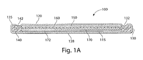
- a desirable button cell 100 configuration comprising a lithium anode 150 and a cathode 170 comprising iron disulfide (FeS 2 ) with separator 160 therebetween is shown in the Fig. 1A .
- the Li/FeS 2 cell as in cell 100 has the following basic discharge reactions (one step mechanism):
- buttons cell 100 shown in Fig. 1A may be in the form of a primary (nonrechargeable) cell.
- nonrechargeable is meant that the cell is intended to be discarded after it has been discharged.
- a disk-shaped cylindrical cathode housing 130 is formed having an open end 132 and a closed end 138.
- Cathode housing 130 is preferably formed from nickel-plated steel.
- An electrical insulating member 140 preferably a plastic cylindrical member having a hollow core, is inserted into housing 130 so that the outside surface of insulating member 140 abuts and lines the inside surface of housing 130.
- the inside surface of housing 130 may be coated with a polymeric material that solidifies into insulator 140 abutting the inside surface of housing 130.
- Insulator 140 can be formed from a variety of thermally stable insulating materials, for example polypropylene.
- a cathode current collector 115 comprising a metallic grid can be inserted into the cell so that it abuts the inside surface of the closed end 138 of the housing 130.
- the cathode current collector 115 may desirably be composed of a sheet of expanded stainless steel metal foil, having a plurality of openings therein, thus forming a stainless steel grid or screen.
- the expanded stainless steel metal foil is available as EXMET foil 316L-SS from Dexmet Corp.
- the cathode current collector 115 is composed of a sheet of aluminum, which is more conductive.
- the cathode current collector 115 may be a sheet of aluminum alloyed with common aluminum alloy metals such as magnesium, copper, and zinc.) Such aluminum current collector sheet 115 may also have a plurality of small openings therein, thus forming an aluminum grid.
- the cathode current collector 115 can be welded onto the inside surface of the closed end 138 of the housing 130. (Optionally, the same type of current collector grid, preferably of expanded stainless steel metal foil with openings therein, may be welded to the inside surface of the closed end of the anode cover 120.)
- An optional conductive carbon base layer 172 comprising a mixture of graphite and polytetrafluoroethylene (PTFE) binder can be compressed into the cathode current collector 115.
- the cathode material 170 comprising the FeS 2 active particles may then be coated onto such conductive base layer 172. This may be termed a "staged" cathode construction.
- the cathode material 170 comprising iron disulfide (FeS 2 ) or any mixture including iron disulfide (FeS 2 ) as active cathode material, may thus be inserted over optional conductive base layer 172 so that it overlies current collector sheet 115.
- the cathode active material that is, the material undergoing useful electrochemical reaction, in cathode layer 170 can be composed entirely of iron disulfide (FeS 2 ).
- the cathode 170 comprising iron disulfide (FeS 2 ) powder dispersed therein can be prepared in the form of a slurry which may be coated on both sides of a conductive metal foil, preferably an aluminum or stainless steel foil.
- Such aluminum or stainless steel foil may have openings therethrough, thus forming a grid or screen.
- the cathode 170 comprising iron disulfide (FeS 2 ) powder dispersed therein can be prepared in the form of a slurry which is coated on just the side of an aluminum or stainless steel foil facing separator 160.
- a conductive base layer 172 as above described, may be employed in which case cathode 170 is inserted in the cell so that it overlies conductive base layer 172 as shown in Fig. 1A .
- the cathode 170 comprising iron disulfide (FeS 2 ) powder dispersed therein can be prepared in the form of a slurry which may be coated directly onto a conductive substrate sheet 115 to form a cathode composite.
- conductive substrate sheet 115 is formed of a sheet of aluminum (or aluminum alloy), as above described, and may have a plurality of small apertures therein, thus forming a grid.
- the conductive substrate sheet 115 may be a sheet of stainless steel, desirably in the form of expanded stainless steel metal foil, having a plurality of small apertures therein.
- the cathode slurry comprises 2 to 4 wt% of binder (Kraton G1651 elastomeric binder from Kraton Polymers, Houston Texas.); 50 to 70 wt% of active FeS 2 powder; 4 to 7 wt% of conductive carbon (carbon black and graphite); and 25 to 40 wt% of solvent(s).
- binder Kelon G1651 elastomeric binder from Kraton Polymers, Houston Texas.
- active FeS 2 powder 4 to 7 wt% of conductive carbon (carbon black and graphite); and 25 to 40 wt% of solvent(s).
- the carbon black may include in whole or in part acetylene black carbon particles.
- the term carbon black as used herein shall be understood to extend to and include carbon black and acetylene black carbon particles.
- the Kraton G1651 binder is an elastomeric block copolymer (styrene-ethylene/butylene (SEBS) block copolymer) which is a film-former. This binder possesses sufficient affinity for the active FeS 2 and carbon black particles to facilitate preparation of the wet cathode slurry and to keep these particles in contact with each other after the solvents are evaporated.
- SEBS styrene-ethylene/butylene
- the FeS 2 powder may have an average particle size between about 1 and 100 micron, desirably between about 10 and 50 micron.
- a desirable FeS 2 powder is available under the trade designation Pyrox Red 325 powder from Chemetall GmbH, wherein the FeS 2 powder has a particle size sufficiently small that of particles will pass through a sieve of Tyler mesh size 325 (sieve openings of 0.045 mm). (The residue amount of FeS 2 particles not passing through the 325 mesh sieve is 10% max.)
- the graphite is available under the trade designation Timrex KS6 graphite from Timcal Ltd. Timrex graphite is a highly crystalline synthetic graphite.
- Timrex graphite is preferred because of its high purity.
- the carbon black is available under the trade designation Super P conductive carbon black (BET surface of 62 m 2 /g) from Timcal Co.
- the solvents preferably include a mixture of C 9 -C 11 (predominately C 9 ) aromatic hydrocarbons available as ShellSol A100 hydrocarbon solvent (Shell Chemical Co.) and a mixture of primarily isoparaffins (average M.W. 166, aromatic content less than 0.25 wt.%) available as Shell Sol OMS hydrocarbon solvent (Shell Chemical Co.).
- the weight ratio of ShellSol A100 to ShellSol OMS solvent is desirably at a 4:6 weight ratio.
- the ShellSol A 100 solvent is a hydrocarbon mixture containing mostly aromatic hydrocarbons (over 90 wt% aromatic hydrocarbon), primarily C 9 to C 11 aromatic hydrocarbons.
- the ShellSol OMS solvent is a mixture of isoparaffin hydrocarbons (98 wt.% isoparaffins, M.W. about 166) with less than 0.25 wt% aromatic hydrocarbon content.
- the slurry formulation may be dispersed using a double planetary mixer. Dry powders are first blended to ensure uniformity before being added to the binder solution in the mixing bowl.
- a preferred cathode slurry mixture is presented in Table 1: Table I Cathode Slurry Wet Slurry ( wt. %) Binder 2.0 (Kraton G1651) Hydorcarbon Solvent 13.4 (ShellSol A100) (ShellSol OMS) 20.2 FeS 2 Powder (Pyrox Red 325) 58.9 Graphite 4.8 (Timrex KS6) Carbon Black 0.7 (Super P) Total 100.0
- the total solids content of the wet cathode slurry mixture 170 is shown in above Table 1 is 66.4 wt.%
- the wet cathode slurry 170 is applied to the current collector 115 using intermittent roll coating technique.
- current collector sheet 115 is optionally precoated with a carbon base layer 172 before the wet cathode slurry is applied.
- the cathode slurry coated on the metal substrate 115 is dried gradually adjusting or ramping up the temperature from an initial temperature of 40° C to a final temperature of about 130° C in an oven until the solvent has all evaporated. (Drying the cathode slurry in this manner avoids cracking.) This forms a dry cathode coating 170 comprising FeS 2 , carbon particles, and binder on the metal substrate 115.
- a representative desirable thickness of dry cathode coating 170 is between about 0.172 and 0.188 mm, preferably about 0.176 mm.
- the dry cathode coating 170 thus has the following desirable formulation: FeS 2 powder (89 wt.%); Binder (Kraton G1651), 3 wt.%; Graphite (Timrex KS6), 7 wt.%, and Carbon Black (Super P), 1 wt%.
- the carbon black (Super P carbon black) develops a carbon network which improves conductivity.
- the cathode composite comprising current collector sheet 115, cathode base layer 172, and dry cathode coating 170 thereon may then be inserted into cathode housing 130.
- a nonaqueous electrolyte for the Li/FeS 2 cell may then be added so that it fully penetrates through separator sheet 160 and cathode layer 170.
- a nonaqueous electrolyte mixture can be added so that it becomes absorbed into the separator and cathode coating.
- the desired nonaqueous electrolyte comprises a lithium salt or mixture of lithium salts dissolved in an organic solvent.
- the nonaqueous electrolyte comprises a lithium salt dissolved in an organic solvent preferably comprising dimethoxyethane, and a cyclic organic carbonate, preferably ethylene carbonate and propylene carbonate.
- the desired electrolyte solvent mixture thus comprises a cyclic organic carbonate, preferably a cyclic glycol carbonate such as ethylene carbonate, propylene carbonate or butylene carbonate, and mixtures thereof, in admixture with dimethoxyethane, preferably 1,2 dimethoxyethane.
- the electrolyte solvent may also include dimethylcarbonate and/or ethyl methyl carbonate).
- a desirable solvent thus comprises dimethoxyethane (DME), ethylene carbonate (EC), and propylene carbonate (PC).
- DME dimethoxyethane
- EC ethylene carbonate
- PC propylene carbonate
- a desirable electrolyte for the Li/FeS 2 wound cell has been determined to comprise lithium salts lithium trifluoromethanesulfonate having the chemical formula LiCF 3 SO 3 which can be referenced simply as LiTFS and/or the lithium salt Li(CF 3 SO 2 ) 2 N (LiTFSI) dissolved in the above organic solvent mixture comprising dimethoxyethane (DME), ethylene carbonate (EC), and propylene carbonate (PC).
- elemental iodine is added to the above electrolyte mixture so that it comprises between about 0.01 and 5 wt.% of the electrolyte mixture, preferably about 0.5 wt.% of the nonaqueous electrolyte.
- a first preferred electrolyte (Electrolyte 1) has been determined to be an electrolyte solution comprising 0.3 molar (0.3 mol/liter) LiCF 3 SO 3 (LiTFS) salt and 0.6 molar (0.6 mol/liter) Li(CF 3 SO 2 ) 2 N (LiTFSI) salt, 0.25 wt% LiClO4 and 0.5 wt% elemental iodine dissolved in an organic solvent mixture comprising about 95 wt% dimethoxyethane (DME), 2 wt.% ethylene carbonate (EC), and 3 wt.% propylene carbonate (PC).
- the elemental iodine can be eliminated but better cell performance is obtained with the iodine added.
- the electrolyte mixture is desirably added on the basis of about 0.4 gram electrolyte solution per gram FeS 2 .
- a second preferred electrolyte (Electrolyte 2) has been determined to be an electrolyte solution comprising 0.54 molar (0.54 mol/liter) LiCF 3 SO 3 (LiTFS) salt and 0.36 molar (0.36 mol/liter) Li(CF 3 SO 2 ) 2 N (LiTFSI) salt, 0.25 wt% LiClO4 and 0.5 wt% elemental iodine dissolved in an organic solvent mixture comprising about 75 wt.% dimethoxyethane (DME), 10 wt.% ethylene carbonate (EC), and 15 wt.% propylene carbonate (PC).
- the elemental iodine can be eliminated but better cell performance is obtained with the iodine added.
- the electrolyte mixture is desirably added on the basis of about 0.4 gram electrolyte solution per gram FeS 2 .
- a layer of anode material 150 may then be placed over separator sheet 160.
- the anode cover 120 formed preferably from nickel-plated steel, is inserted into open end 132 of housing 130 and peripheral edge 135 of housing 130 is crimped over the exposed insulator edge 142 of insulating member 140. The peripheral edge 135 bites into insulator edge 142 closing housing 130 and tightly sealing the cell contents therein.
- the anode cover 120 also functions as the negative terminal of the cell and housing 130 at the closed end 138 functions as the positive terminal of the cell.
- the Li/FeS 2 cell may be in the configuration of a cylindrical cell 10 as shown in Fig. 1 .
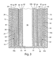
- the cylindrical cell 10 may have a spirally wound anode sheet 40, cathode 60 with separator sheet 50 therebetween as shown in Figs. 2-5 .
- the Li/FeS 2 cell 10 internal configuration, apart from the difference in cathode composition, may be similar to the spirally wound configuration shown and described in U.S. patent 6,443,999 .
- the anode sheet 40 as shown in the figures comprises lithium metal and the cathode sheet 60 comprises iron disulfide (FeS 2 ) commonly known as "pyrite".
- the cell is preferably cylindrical as shown in the figures and may be of any size, for example, AAAA (42 x 8mm), AAA (44 x 9 mm), AA (49 x 12 mm), C (49 x 25 mm) and D (58 x 32 mm) size.
- cell 10 depicted in Fig. 1 may also be a 2/3 A cell (35 x 15mm). However, it is not intended to limit the cell configuration to cylindrical shape.
- the cell of the invention may have an anode comprising lithium metal and a cathode comprising iron disulfide (FeS 2 ) having the composition and nonaqueous electrolyte as herein described in the form of a spirally wound prismatic cell, for example a rectangular cell having the overall shape of a cuboid.
- FeS 2 iron disulfide
- a preferred shape of the cell casing (housing) 20 is cylindrical as shown in Fig. 1 .
- Casing 20 is preferably formed of nickel plated steel.
- the cell casing 20 ( Fig. 1 ) has a continuous cylindrical surface.
- the spiral wound electrode assembly 70 ( Fig. 3 ) comprising anode 40 and cathode composite 62 with separator 50 therebetween can be prepared by spirally winding a flat electrode composite 13 ( Figs. 4 and 5 ).
- Cathode composite 62 comprises a layer of cathode 60 comprising iron disulfide (FeS 2 ) coated onto metallic substrate 65 ( Fig. 4 ).
- the electrode composite 13 ( Figs. 4 and 5 ) can be made in the following manner:
- the cathode 60 comprising iron disulfide (FeS 2 ) powder dispersed therein can be initially prepared in the form of a wet slurry which is coated onto a conductive substrate sheet 65, preferably a sheet of aluminum or stainless steel expanded metal foil, to form a cathode composite sheet 62 ( Fig. 4 ).
- a conductive substrate sheet 65 preferably a sheet of aluminum or stainless steel expanded metal foil
- an aluminum sheet 65 it may be a sheet of aluminum without openings therethrough or may be a sheet of expanded aluminum foil (EXMET expanded aluminum foil) with openings therethrough thus forming a grid or screen.
- the wet cathode slurry mixture having the composition shown above in Table 1 comprising iron disulfide (FeS 2 ), binder, conductive carbon and solvents is prepared by mixing the components shown in Table 1 until a homogeneous mixture is obtained.
- the above quantities (Table 1) of components of course can be scaled proportionally so that small or large batches of cathode slurry can be prepared.
- the wet cathode slurry thus preferably has the following composition: FeS 2 powder (58.9 wt.%); Binder, Kraton G1651 (2 wt.%); Graphite, Timrex KS6 (4.8 wt%), Actylene Black, Super P (0.7 wt%), Hydrocarbon Solvents, ShellSol A100 (13.4 wt%) and ShelSol OMS (20.2 wt%)
- the cathode slurry is coated onto one side (optionally both sides) of a conductive substrate or grid 65, preferably a sheet of aluminum, or stainless steel expanded metal foil.
- the cathode slurry coated on the metal substrate 65 is dried in an oven preferably gradually adjusting or ramping up the temperature from an initial temperature of 40° C to a final temperature not to exceed 130° C for about 1/2 hour or until the solvent has all evaporated.
- This forms a dry cathode coating 60 comprising FeS 2 , carbon particles, and binder on the metal substrate 65 and thus forms the finished cathode composite sheet 62 shown best in Fig. 4 .
- a calendering roller is then applied to the coating to obtain the desired cathode thicknesses.
- the desired thickness of dry/ cathode coating 60 is between about 0.172 and 0.188 mm, preferably about 0.176 mm.
- the dry cathode coating thus has the following desirable formulation: FeS 2 powder (89.0 wet.%); binder, Kraton G1651 elastomer (3.0 wt.%); conductive carbon particles, preferably graphite (7 wl.%) available as Timrex KS6 graphite from Timcal Ltd and conductive carbon black (1 wt%) available as Super P conductive carbon black from Timcal.
- the carbon black develops a carbon network which improves conductivity.
- between about 0 and 90 percent by weight of the total carbon particles may be graphite.
- the graphite if added may be natural, synthetic or expanded graphite and mixtures thereof.
- the dry cathode coating may typically comprise between about 85 and 95 wt.% iron disulfide (FeS 2 ); between about 4 and 8 wt.% conductive carbon; and the remainder of said dry coating comprising binder material.
- the cathode substrate 65 can be a sheet of conductive metal foil, for example, a sheet of aluminum or stainless steel, with or without apertures therein.
- the cathode conductive substrate 65 is preferably a sheet of aluminum.
- the aluminum sheet 65 may have a plurality of small apertures therein, thus forming a grid or screen.
- cathode conductive substrate 65 may be formed of a sheet of stainless steel expanded metal foil (EXMET stainless steel foil from Dexmet Company, Branford, Conn.) having a basis weight of about 0.024 g/cm 2 forming a mesh or screen with openings therein.
- the EXMET expanded stainless steel foil may have openings therethrough forming a grid or screen.
- the cathode conductive substrate 65 secures the cathode coating 60 and functions as a cathode current collector during cell discharge.
- the anode 40 can be prepared from a solid sheet of lithium metal.
- the anode 40 is desirably formed of a continuous sheet of lithium metal (99.8 % pure).
- the anode 40 can be an alloy of lithium and an alloy metal, for example, an alloy of lithium and aluminum.
- the alloy metal is present in very small quantity, preferably less than 1 percent by weight of the lithium alloy.
- the term "lithium or lithium metal" as used herein and in the claims is intended to include in its meaning such lithium alloy.
- the lithium sheet forming anode 40 does not require a substrate.
- the lithium anode 40 can be advantageously formed from an extruded sheet of lithium metal having a thickness of desirably between about 0.10 and 0.20 mm desirably between about 0.12 and 0.19 mm, preferably about 0.15 mm for the spirally wound cell.
- Individual sheets of electrolyte permeable separator material 50 preferably of microporous polypropylene having a thickness of about 0.025 mm is inserted on each side of the lithium anode sheet 40 ( Figs. 4 and 5 ).
- the microporous polypropylene desirably has a pore size between about 0.001 and 5 micron.
- the first (top) separator sheet 50 ( Fig. 4 ) can be designated the outer separator sheet and the second sheet 50 ( Fig. 4 ) can be designated the inner separator sheet.
- the cathode composite sheet 62 comprising cathode coating 60 on conductive substrate 65 is then placed against the inner separator sheet 50 to form the flat electrode composite 13 shown in Fig. 4 .
- the flat composite 13 ( Fig.
- electrode spiral assembly 70 ( Fig. 3 ).
- the winding can be accomplished using a mandrel to grip an extended separator edge 50b ( Fig. 4 ) of electrode composite 13 and then spirally winding composite 13 clockwise to form wound electrode assembly 70 ( Fig.3 ).
- separator portion 50b appears within the core 98 of the wound electrode assembly 70 as shown in Figs. 2 and 3 .
- the bottom edges 50a of each revolution of the separator may be heat formed into a continuous membrane 55 as shown in Fig. 3 and taught in U.S. patent 6,443,999 .
- the electrode spiral 70 has separator material 50 between anode sheet 40 and cathode composite 62.
- the spirally wound electrode assembly 70 has a configuration ( Fig. 3 ) conforming to the shape of the casing body.
- the spirally wound electrode assembly 70 is inserted into the open end 30 of casing 20.
- the outer layer of the electrode spiral 70 comprises separator material 50 shown in Figs.
- An additional insulating layer 72 for example, a plastic film such as polyester tape, can desirably be placed over a of the outer separator layer 50, before the electrode composite 13 is wound.
- the spirally wound electrode 70 will have insulating layer 72 in contact with the inside surface of casing 20 ( Figs. 2 and 3 ) when the wound electrode composite is inserted into the casing.
- the inside surface of the casing 20 can be coated with electrically insulating material 72 before the wound electrode spiral 70 is inserted into the casing.
- a nonaqueous electrolyte mixture can then be added to the wound electrode spiral 70 after it is inserted into the cell casing 20.
- the desired nonaqueous electrolyte comprises a lithium salt dissolved in an organic solvent.
- a desirable electrolyte solvent comprises dimethoxyethane (DME), ethylene carbonate (EC), and propylene carbonate (PC).
- DME dimethoxyethane
- EC ethylene carbonate
- PC propylene carbonate
- a desirable electrolyte for the Li/FeS 2 wound cell 10 has been determined to comprise lithium salts lithium trifluoromethanesulfonate having the chemical formula LiCF 3 S0 3 which can be referenced simply as LiTFS and/or the lithium salt Li(CF 3 SO 2 ) 2 N (LiTFSI) dissolved in the above organic solvent mixture comprising dimethoxyethane (DME), ethylene carbonate (EC), and propylene carbonate (PC).
- DME dimethoxyethane
- EC ethylene carbonate
- PC propylene carbonate
- elemental iodine is added to the above electrolyte mixture so that it comprises between about 0.01 and 5 wt.% of the electrolyte mixture, preferably about 0.5 wt.% of the nonaqueous electrolyte mixture.
- a first preferred electrolyte (Electrolyte 1) has been determined to be an electrolyte solution comprising 0.3 molar (0.3 mol/liter) LiCF 3 SO 3 (LiTFS) salt and 0.6 molar (0.6 mol/liter) Li(CF 3 SO 2 ) 2 N (LiTFSI) salt, 0.25 wt% LiClO4 and 0.5 wt% elemental iodine dissolved in an organic solvent mixture comprising about 95 wt% dimethoxyethane (DME), 2 wt.% ethylene carbonate (EC), and 3 wt.% propylene carbonate (PC).
- the elemental iodine can be eliminated but better cell performance is obtained with the iodine added.
- the electrolyte mixture is desirably added on the basis of about 0.4 gram electrolyte solution per gram FeS 2 .
- a second preferred electrolyte (Electrolyte 2) has been determined to be an electrolyte solution comprising 0.54 molar (0.54 mol/liter) LiCF 3 SO 3 (LiTFS) salt and 0.35 molar (0.35 mol/liter) Li(CF 3 SO 2 ) 2 N (LiTFSI) salt, 0.25 wt% LiClO4 and 0.5 wt% elemental iodine dissolved in an organic solvent mixture comprising about 75 wt.% dimethoxyethane (DME), 10 wt.% ethylene carbonate (EC), and 15 wt.% propylene carbonate (PC).
- DME dimethoxyethane
- EC ethylene carbonate
- PC propylene carbonate
- the electrolyte mixture is desirably added on the basis of about 0.4 gram electrolyte solution per gram FeS 2 .
- An end cap 18 ( Fig. 2 ) forming the cell's positive terminal 17 may have a metal tab 25 (cathode tab) which can be welded on one of its sides to inside surface of end cap 18.
- Metal tab 25 is preferably of aluminum or aluminum alloy.
- a portion of the cathode substrate 65 may be flared along its top edge forming an extended portion 64 extending from the top of the wound spiral as shown in Fig. 2 .
- the flared cathode substrate portion 64 can be welded to the exposed side of metal tab 25 before the casing peripheral edge 22 is crimped around the end cap 18 with peripheral edge 85 of insulating disk 80 therebetween to close the cell's open end 30.
- End cap 18 desirably has a vent 19 ( Fig.
- Positive terminal 17 is desirably an integral portion of end cap 18.
- terminal 17 can be formed as the top of an end cap assembly of the type described in U.S. patent 5,879,832 , which assembly can be inserted into an opening in the surface of end cap 18 and then welded thereto.
- a metal tab 44 (anode tab), preferably of nickel can be pressed into a portion of the lithium metal anode 40.
- Anode tab 44 can be pressed into the lithium metal at any point within the spiral, for example, it can be pressed into the lithium metal at the outermost layer of the spiral as shown in Fig. 5 .
- Anode tab 44 can be embossed on one side forming a plurality of raised portions on the side of the tab to be pressed into the lithium.
- the opposite side of tab 44 can be welded to the inside surface of the casing either to the inside surface of the casing side wall 24 or more preferably to the inside surface of close end 35 of casing 20 as shown in Fig. 3 .
- anode tab 44 it is preferable to weld anode tab 44 to the inside surface of the casing closed end 35, since this is readily accomplished by inserting an electrical spot welding probe (an elongated resistance welding electrode) into the cell core 98. Care should be taken to avoid contacting the welding probe to the separator starter tab 50b which is present along a portion of the outer boundary of cell core 98.
- an electrical spot welding probe an elongated resistance welding electrode
- the primary lithium cell 10 may optionally also be provided with a PTC (positive thermal coefficient) device 95 located under the end cap 18 and connected in series between the cathode 60 and end cap 18 ( Fig. 2 ).
- PTC positive thermal coefficient
- Such device protects the cell from discharge at a current drain higher than a predetermined level.
- an abnormally high current e.g., higher than about 6 to 8 Amp
- the resistance of the PTC device increases dramatically, thus shutting down the abnormally high drain.
- devices other than vent 19 and PTC device 95 may be employed to protect the cell from abusive use or discharge.
- a coin shaped cathode housing 130 of nickel plated steel and a coin shaped anode housing (cover) 120 of nickel plated steel is formed of a similar configuration shown in Fig. 1A .
- the finished cell 100 had an overall diameter of about 25 mm and a thickness of about 3 mm.
- the weight of FeS 2 in the cathode housing 130 was 0.125 g.
- the lithium was in electrochemical excess.
- each cell 100 an Arbor press with a 0.780-inch die was used to punch out two stainless steel grids (316L-SS EXMET expanded metal foil).
- One stainless steel grid was centered inside of coin cell cathode housing 130 forming cathode current collector sheet 115.
- the other stainless steel grid (not shown) was resistance welded to the inside surface of closed end of the anode housing (cover) 120.
- the grids were welded to their respective housings using a Hughes opposing tip tweezers welder.
- the welder was set at 20 watts-seconds and a medium pulse.
- the welds that were formed were evenly spaced around the perimeters of the grids over intersecting points of mesh strands. For each cell, six to eight welds were formed per grid.
- a plastic insulating disk (grommet) 140 was then attached to the edge of anode cover 120 ( Fig. 1A ).
- a lithium disk 150 formed of a sheet of lithium metal having a thickness of 0.032 inch (0.813 mm) was punched out in a dry box using an Arbor press and a 0.75 inch hand punch.
- the lithium disk 150 forming the cell's anode was then pressed onto the stainless steel grid against the inside surface of the closed end of anode cover 120 using an Arbor press.
- a microporous polypropylene separator 160 (Celgard CG2400 separator from Celgard, Inc.) was cut into eight-inch strips and punched out using a hand punch having a diameter of 0.9375 inch and set aside.
- Cathode conductive base layer 172 was prepared as follows:
- a cathode slurry was then prepared and coated over one side of an aluminum sheet (not shown).
- the components of the cathode slurry comprising iron disulfide (FeS 2 ) were mixed together in the following proportion:
- the wet cathode slurry on the aluminum sheet (not shown) was then dried in an oven between 40° C and 130° C until the solvent in the cathode slurry all evaporated, thus forming a dry cathode coating 170 comprising FeS 2 , conductive carbon and elastomeric binder on a side of the aluminum sheet.
- the aluminum sheet carrying cathode coating 170 was an aluminum foil of 20 micron thickness.
- the same composition of wet cathode slurry was then coated onto the opposite side of the aluminum sheet and similarly dried.
- the dried cathode coatings on each side of the aluminum sheet was calendered to form a dry cathode 170 having a total final thickness of about 0.176 mm, which includes the 20 micron thick aluminum foil.
- the dry cathode coating 170 had the following composition:
- the composite of the dry cathode coating 170 coated on both sides of the aluminum sheet was then die punched into the cathode housing 130 onto carbon base layer 172. This was done by placing cathode housing 130 within a die. A cut to size composite of aluminum sheet coated on both sides with dry cathode coating 170 was then aligned directly over cathode base layer 172 within housing 130. A ram was then inserted into the die holding housing 130, and the die was moved to a hydraulic press. Four metric tons of force was applied using the press to punch the composite into the cathode housing 130 so that it was impacted against cathode base layer 172. The die was then inverted and the housing 130 gently removed from the die. The surface of the exposed cathode layer 170 had a smooth, consistent texture. The finished cathode coin was then placed in a vacuum oven and was heated at 150° C for 16 hours.
- An electrolyte solution (Electrolyte 1) was prepared comprising 0.3 molar (0.3 mol/liter) LiCF 3 SO 3 (LiTFS) salt and 0.6 molar (0.6 mol/liter) Li(CF 3 SO 2 ) 2 N (LiTFSI) salt, 0.25 wt% LiClO4 and 0.5 wt% elemental iodine dissolved in an organic solvent mixture comprising about 95 wt% dimethoxyethane (DME), 2 wt.% ethylene carbonate (EC), and 3 wt.% propylene carbonate (PC).
- the electrolyte mixture is desirably added on the basis of about 0.4 gram electrolyte solution per gram FeS 2 .
- the cathode coin that is, cathode housing 130 with dried cathode 170 therein, was placed into a glass coin holder for vacuum filling with electrolyte.
- a rubber stopper with an attached burette fill tube was placed on top of the cathode coin holder. The fill valve on the tube was closed and the vacuum valve was opened for approximately one minute.
- the above described electrolyte containing 0.5 wt.% elemental iodine was slowly added using a pipette.
- the vacuum valve was closed and the burette valve was opened. After about one minute, the vacuum valve was shut off, and the fill valve was opened slowly to fill the cathode housing 130 and allow cathode 170 to absorb most of the electrolyte.
- the filled cathode coin was removed using plastic tweezers, and was placed on the base of a crimper so that it sat securely on the base.
- a pipette was used to flood the coin with the excess of electrolyte that was left over in the glass holder.
- microporous polypropylene separator 160 (Celgard CG2400 separator) was placed on top of the electrolyte wet cathode layer 170 and was centered. The cathode housing 130 was then re-flooded with electrolyte.
- An anode coin that is, the anode cover 120 with lithium anode sheet 150 therein was placed on top of the cathode housing 130 and was centered within a mechanical crimper until the anode cover 120 fit evenly inside of the cathode housing 130.
- a mechanical crimper arm was then pulled down all of the way to crimp the peripheral edge 135 of the cathode housing 130 over the edge of insulating disk 140 thus forming fresh coin cell 100. This process was repeated for each cell. After each cell had been formed, the outside surfaces of the housings of the cells were wiped cleaned with methanol.
- Identical coin cells 100 were prepared fresh as above described employing the above indicated Electrolyte 1 solution. The cells were then divided into two groups.
- One cell group (Group I Test Cells) was subjected to a preconditioning protocol of the invention involving a two step pulsed discharge with intermediate storage (step rest) carried out at above ambient temperature between steps. That is, after the first pulsed discharge step, the cell was stored for a period at a temperature above ambient, specifically at about 60° C, and then the Group I test cells was subjected to a second pulsed discharge step.
- the other cell group (Group II Control Cells) was the control group which was subjected to only a one step pulsed discharge and was not stored at any time at a temperature above ambient. In both the Group I and Group II cells the same small fraction ( ⁇ 10%) of the cell's total theoretical capacity was expended during the preconditioning protocol.
- the following specific preconditioning protocol of the invention applied to the Group I test cells involved a two step pulsed predischarge with elevated temperature storage between the steps. Each discharge pulse was at 35 mAmp for 7 seconds, followed by an intermittent pulse rest of 22 seconds. Fresh Group I cells were subjected to:
- step rest the Group I test cells were subjected to storage (step rest) at a temperature of 60° C for a period of 22-24 hours.
- the Group I test cells were then subjected to a final storage (step rest) at a temperature of 60° C for a period of 22-24 hours.
- the Group II cells were subjected to only one pulsed discharge step without any storage at above ambient temperature. Each discharge pulse was at 35 mAmp for 7 seconds, followed by an intermittent pulse rest of 22 seconds. Fresh Group II control cells were subjected to the following one step predischarge protocol:
- the discharge capacity of the Group I test cells and Group II control cells were tested using a test that was meant to mimic the use of the cell in a digital camera scaled down based on the weight of cathode active material.
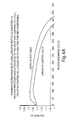
- the digital Camera simulation test consists of the following pulsed test protocol: Each pulsed cycle as indicated on the x-axis of Fig. 6 consisted of: 10 intermediate cycles wherein each intermediate cycle consisted of both a 26 milliwatt pulse for 2 seconds followed immediately by a 12 milliWatt pulse for 28 seconds and then followed by 55 minutes rest. These pulsed cycles were repeated until a cut off voltage of 1.05 Volt is reached.
- the running voltage profile of the Group I test cells subjected to the preconditioning protocol of the invention was on average about 100 milliVolts higher than the Group II control cells. This resulted in an energy output (at cut off voltage of 1.05 Volt) of the Group I cells which was clearly much higher than the energy output of Group II cells.
- the energy output of the Group II test cells which were subjected to the two step predischarge protocol of the invention was about 15 percent higher than the Group I control cells as measured at common cut off voltage of 1.05 volts.
- Electrolyte 1A was employed in each cell Group IA and IIA instead of Electrolyte 1.
- the Electrolyte 1A was the same formulation as Electrolyte 1 except that there was no elemental iodine added to the electrolyte solution.
- Electrolyte 1A used in Group IA test cells and Group IIA control cells had the following formulation:
- the Electrolyte 1A solution was prepared comprising 0.3 molar (0.3 mol/liter) LiCF 3 SO 3 (LiTFS) salt and 0.6 molar (0.6 mol/liter) Li(CF 3 SO 2 ) 2 N (LiTFSI) salt, and 0.25 wt% LiClO4 dissolved in an organic solvent mixture comprising about 95 wt% dimethoxyethane (DME), 2 wt.% ethylene carbonate (EC), and 3 wt.% propylene carbonate (PC).
- the electrolyte mixture was added on the basis of about 0.4 gram electrolyte solution per gram FeS 2 .
- the Group IA test cells were subjected to the same two step preconditioning protocol of the invention as above described with respect to the Group I test cells (see Test Experiment 1).
- the Group IIA control cells were subjected to the same one step preconditioning protocol as described above with respect to the Group II control cells (see Test Experiment 1).
- the Group IA test cells and Group II control cells were then discharged to a cut off voltage of 1.05 Volt using the same digital camera simulation discharge regimen as described above in Test Experiment 1. Although there was no elemental iodine added to Electrolyte 1A used in the Group IA and Group IIA cells, the Group IA test cells (subjected to the two step preconditioning protocol of the invention) still exhibited a higher running voltage profile than the Group IIA control cells (which were subjected to only a one step preconditioning protocol). As may be seen from Fig.
- the running voltage profile of the Group IIA test cells was on average about 50 millivolts higher than the voltage discharge profile of the control cells. This resulted in an energy output (at cut off voltage of 1.05 Volt) of the Group IA test cells which was clearly higher than the energy output of Group IIA control cells.
- the energy output of the Group IA test cells which were subjected to the two step predischarge protocol of the invention was about 10 percent higher than the Group IIA control cells as measured at common cut off voltage of 1.05 Volts.
- Group III test cells Two Groups of cells Group III test cells and Group IV control were prepared.
- the Group III test cells were identical to the Group I test cells (see test experiment 1) and the Group IV control cells were identical to the Group II control cells (test experiment 1) in every respect except that Electrolyte 2 was used instead of Electrolyte 1.
- Electrolyte 2 therein of following formulation:
- the Electrolyte 2 formulation comprised 0.54 molar (0.54 mol/liter) LiCF 3 SO 3 (LiTFS) salt and 0.36 molar (0.36 mol/liter) Li(CF 3 SO 2 ) 2 N (LiTFSI) salt, 0.25 wt% LiClO4 and 0.5 wt% elemental iodine dissolved in an organic solvent mixture comprising about 75 wt.% dimethoxyethane (DME), 10 wt.% ethylene carbonate (EC), and 15 wt.% propylene carbonate (PC).
- DME dimethoxyethane
- EC ethylene carbonate
- PC propylene carbonate
- the electrolyte mixture was added on the basis of about 0.4 gram electrolyte solution per gram FeS 2 .
- the Group III test cells were subjected to the same two step preconditioning protocol of the invention as above described with respect to the Group I test cells (see Test Experiment 1).
- the Group IV control cells were subjected to the same one step preconditioning protocol as described above with respect to the Group II cells (see Test Experiment 1).
- the Group III test cells and Group IV control cells were then discharged to a cut off voltage of 1.05 Volt using the same digital camera simulation discharge regimen as described above in Test Experiment 1.
- the running voltage profile of the Group III test cells was on average about 50 millivolts higher than the running voltage profile of the Group IV control cells.
- the energy output of the Group III test cells, which were subjected to the two step predischarge protocol of the invention, was about 8 percent higher than the Group IV control cells as measured at common cut off voltage of 1.05 Volts.
- Li/FeS2 fresh cells which were subjected to the two step pulsed preconditioning protocol of the invention which also included storage at elevated temperature between the two pulsed steps exhibited better performance than the same cells which were only subjected to a one step preconditioning protocol without elevated temperature storage. (Both the test cells and control cells were subjected to the same amount of capacity drain, mAmp, during the preconditioning protocols.)
- test cells which were subjected to the two step preconditioning protocol of the invention which included elevated temperature storage between steps exhibited a higher running voltage profile and higher energy output than the same cells with same electrolyte which were subjected to only a one step pulsed predischarge protocol without elevated temperature storage.
- Even better cell performance of the test cells subjected to the two step predischarge protocol of the invention was achieved when elemental iodine was also added to the electrolyte solution.
- improved cell performance was obtained when of the test cells were subjected to the two step preconditioning protocol of the invention even when elemental iodine was not added to the electrolyte solution.
- the preconditioning protocol of the invention mitigates the deleterious effect of the lithium passivation layer which normally accumulates on the surface of the exposed lithium anode surface, possibly by altering the chemistry of said lithium passivation layer.
- Li/FeS 2 cell performance can be improved when the cells are first subjected to the above described preconditioning protocol of the invention.
Landscapes
- Chemical & Material Sciences (AREA)
- Chemical Kinetics & Catalysis (AREA)
- Electrochemistry (AREA)
- General Chemical & Material Sciences (AREA)
- Engineering & Computer Science (AREA)
- Manufacturing & Machinery (AREA)
- Materials Engineering (AREA)
- Inorganic Chemistry (AREA)
- Battery Electrode And Active Subsutance (AREA)
- Primary Cells (AREA)
Abstract
Description
- The invention relates to a method for preconditioning a primary cell having an anode comprising lithium and a cathode comprising iron disulfide. A fresh cell is subjected to a pulsed discharge step followed by step rest at elevated temperature, preferably followed by a second pulsed discharge step, thereby preconditioning the cell and improving cell performance.
- Primary (non-rechargeable) electrochemical cells having an anode of lithium are known and are in widespread commercial use. The anode is comprised essentially of lithium metal. Such cells typically have a cathode comprising manganese dioxide, and electrolyte comprising a lithium salt such as lithium trifluoromethane sulfonate (LiCF3SO3) dissolved in a nonaqueous solvent. The cells are referenced in the art as primary lithium cells (primary Li/MnO2 cells) and are generally not intended to be rechargeable, that is, they are intended to be discarded after they have been discharged. Alternative primary lithium cells with lithium metal anodes but having different cathodes are also known. Such cells, for example, have cathodes comprising iron disulfide (FeS2) and are designated Li/FeS2 cells. The iron disulfide (FeS2) is also known as pyrite. The Li/MnO2 cells or Li/FeS2 cells are typically in the form of cylindrical cells, typically an AA size cell or 2/3A Li/MnO2 cell. The Li/MnO2 cells have a voltage of about 3.0 volts which is twice that of conventional Zn/MnO2 alkaline cells and also have higher energy density (watt-hrs per cm3 of cell volume) than that of alkaline cells. The Li/FeS2 cells have a voltage (fresh) of between about 1.2 and 1.5 volts which is about the same as a conventional Zn/MnO2 alkaline cell. However, the energy density (watt-hrs per cm3 of cell volume) of the Li/FeS2 cell is also much higher than a comparable size Zn/MnO2 alkaline cell. The theoretical specific capacity of lithium metal is high at 3861.7 mAmp-hr/gram and the theoretical specific capacity of FeS2 is 893.6 mAmp-hr/gram. The FeS2 theoretical capacity is based on a 4 electron transfer from 4Li per FeS2 to result in reaction product of elemental iron Fe and 2Li2S. That is, 2 of the 4 electrons reducing the valence state of Fe+2 in FeS2 to Fe and the remaining 2 electrons reducing the valence of sulfur from -1 in FeS2 to -2 in Li2S.
- Overall the Li/FeS2 cell is much more powerful than the same size Zn/MnO2 alkaline cell. That is for a given continuous current drain, particularly for higher current drain over 200 milliAmp, in the voltage vs. time profile the voltage drops off much less quickly for the Li/FeS2 cell than the Zn/MnO2 alkaline cell. This results in a higher energy obtainable from a Li/FeS2 cell compared to that obtainable for a same size alkaline cell. The higher energy output of the Li/FeS2 cell is also clearly shown more directly in graphical plots of energy (Watt-hrs) versus continuous discharge at constant power (Watts) wherein fresh cells are discharged to completion at fixed continuous power outputs ranging from as little as 0.01 Watt to 5 Watt. In such tests the power drain is maintained at a constant continuous power output selected between 0.01 Watt and 5 Watt. (As the cell's voltage drops during discharge the load resistance is gradually decreased raising the current drain to maintain a fixed constant power output.) The graphical plot Energy (Watt-Hrs) versus Power Output (Watt) for the Li/FeS2 cell is considerably above that for the same size alkaline cell. This is despite that the starting voltage of both cells (fresh) is about the same, namely, between about 1.2 and 1.5 volt.
- Thus, the Li/FeS2 cell has the advantage over same size alkaline cells, for example, AAA, AA, C or D size or any other size cell in that the Li/FeS2 cell may be used interchangeably with the conventional Zn/MnO2 alkaline cell and will have greater service life, particularly for higher power demands. Similarly the Li/FeS2 cell which is primary (nonrechargeable) cell can be used as a replacement for the same size rechargeable nickel metal hydride cells, which have about the same voltage (fresh) as the Li/FeS2 cell.
- The cathode material may be initially prepared in a form such as a slurry mixture, which can be readily coated onto the metal substrate by conventional coating methods. The electrolyte added to the cell must be a suitable nonaqueous electrolyte for the Li/FeS2 system allowing the necessary electrochemical reactions to occur efficiently over the range of high power output desired. The electrolyte must exhibit good ionic conductivity and also be sufficiently stable to the undischarged electrode materials (anode and cathode) and to the resulting discharge products. This is because undesirable oxidation/reduction reactions between the electrolyte and electrode materials (either discharged or undischarged) could thereby gradually contaminate the electrolyte and reduce its effectiveness or result in excessive gassing. This in turn can result in a catastrophic cell failure. Thus, the electrolyte used in Li/FeS2 cell in addition to promoting the necessary electrochemical reactions, should also be stable to discharged and undischarged electrode materials.
- Primary lithium cells are in use as a power source for digital flash cameras, which require operation at higher power demands than is supplied by individual alkaline cells. Primary lithium cells are conventionally formed of an electrode composite comprising an anode formed of a sheet of lithium, a cathode formed of a coating of cathode active material comprising FeS2 on a conductive metal substrate (cathode substrate) and a sheet of electrolyte permeable separator material therebetween. The electrode composite may be spirally wound and inserted into the cell casing, for examples, as shown in
U.S. patent 4,707,421 . A cathode coating mixture for the Li/FeS2 cell is described inU.S. 6,849,360 . A portion of the anode sheet is typically electrically connected to the cell casing which forms the cell's negative terminal. The cell is closed with an end cap which is insulated from the casing. The cathode sheet can be electrically connected to the end cap which forms the cell's positive terminal. The casing is typically crimped over the peripheral edge of the end cap to seal the casing's open end. - The anode in a Li/FeS2 cell can be formed by laminating a layer of lithium on a metallic substrate such as copper. However, the anode may be formed of a sheet of lithium without any substrate.
- The electrolyte used in a primary Li/FeS2 cells is a non aqueous organic electrolyte formed typically of a "lithium salt" dissolved in an "organic solvent". An "organic electrolyte" includes, but is not limited to, an electrolyte comprising a lithium salt (or other salt) dissolved in an organic solvent. Representative lithium salts which may be used in electrolytes for Li/FeS2 primary cells are referenced in
U.S. patents 5,290,414 andU.S. 6,849,360 B2 and include such salts as: Lithium trifluoroinethanesulfonate, LiCF3SO3 (LiTFS); lithium bistrifluoromethylsulfonyl imide, Li(CF3SO2)2N (LiTFSI); lithium iodide, LiI; lithium bronide, LiBr; lithium tetrafluoroborate, LiBF4; lithium hexafluorophosphate, LiPF6; lithium hexafluoroarsenate, LiAsF6; Li(CF3SO2)3C, and various mixtures. - Examples of some organic solvents which are referenced in the art for possible use in connection with organic solvents for electrolytes for primary Li/FeS2 cells are as follows: propylene carbonate (PC), ethylene carbonate (EC), butylene carbonate (BC), dimethoxyethane (DME), ethyl glyme, diglyme and triglyme, dimethoxypropane (DMP), dioxolane (DIOX), 3,5-dimethlyisoxazole (DMI), tetrahydrofuran (THF), diethyl carbonate (DEC), ethylene glycol sulfite (EGS), dioxane, dimethylsulfate (DMS), 3-methyl-2-oxazolidone, and sulfolane (SU), and various mixtures. (See, e.g.
U.S. patents 5,290,414 andU.S. 6,849,360 B2 ). - In
U.S. 5,290,414 is specifically reported use of a beneficial electrolyte for FeS2 cells, wherein the electrolyte comprises a lithium salt dissolved in a solvent comprising dioxolane in admixture with an acyclic (non cyclic) ether based solvent. The acyclic (non cyclic) ether based solvent as referenced may be dimethoxyethane, ethyl glyme, diglyme and triglyme, with the preferred being 1-2 dimetoxyehtane(DME). A specific lithium salt ionizable in such solvent mixture(s) is given as LiCF3SO3 (LiTFS) or Li(CF3SO2)2N (LiTFSI), or mixtures thereof. A cosolvent selected from 3,5-dimethlyisoxazole (DMI), 3-methyl-2-oxazolidone, propylene carbonate (PC), ethylene carbonate (EC), butylene carbonate (BC), and sulfolane. - In
U.S. 6,849,360 B2 is specifically disclosed an electrolyte for an Li/FeS2 cell, wherein the electrolyte comprises the salt lithium iodide dissolved in the organic solvent mixture comprising 1,3-dioxolane (DIOX), 1,2-dimethoxyethane (DME), and small amount of 3,5 dimethylisoxazole (DMI). - Thus, it should be evident from the above representative references that the choice of a particular organic solvent or mixture of different organic solvents for use in conjunction with any one or more lithium salts to produce a suitable electrolyte for the Li/FeS2 cell is challenging. This is not to say that many combinations of lithium salts and organic solvents do not produce a Li/FeS2 cell will not work at all. But rather the problems associated with such cells using an electrolyte formed with just any combination of lithium salt and organic solvent is that the problems encountered will likely be very substantial, thus making the cell impractical for commercial usage. The history of development of lithium cells in general, whether lithium primary cells, e.g. Li/MnO2, Li/FeS2, or rechargeable lithium or lithium ion cells reveals that just any combination of lithium salt and organic solvent cannot be expected to result in a good cell, that is, exhibiting good, reliable performance.
- As an example of a purported advantageous electrolyte mixture the above references reveal advantageous use of dioxolane in combination with an acyclic (non cyclic) ether based solvent, preferably 1,2-dimethoxyethane (DME) to produce an effective electrolyte in conjunction with use of conventional lithium salts. However, dioxolane has the disadvantage of cost and handling.
- Accordingly, it is desired to employ solvents for the Li/FeS2 cell electrolyte which are more cost effective and easier to handle than dioxolane. Such solvents can be selected from cyclic organic carbonates, for example, ethylene carbonate (EC) and propylene carbonate (PC), which are less expensive and easier to store and handle than dioxolane. Ethylene carbonate (EC) and propylene carbonate (PC) alone or in admixture and also in admixture with dimethoxyethane (DME) have produced very suitable solvents for electrolytes for use in connection with Li/MnO2 cells, particularly when the lithium salt for the electrolyte comprises LiCF3SO3 (LITFS). (See, e.g.
U.S. 6,443,999 B1 ) - However, experiments with such electrolytes and electrolyte solvent systems, that is, comprising ethylene carbonate (EC) and propylene carbonate (PC) solvents, while effective in Li/MnO2 cells result in deficiencies when employed, per se, in the context of the Li/FeS2 cell. One of the difficulties is that such ethylene carbonate/ propylene carbonate electrolyte solvent mixtures tend to cause or exacerbate the problem of lithium surface passivation, which normally occurs at least to a degree during the discharge life of the Li/FeS2 cell. Lithium passivation occurs during the Li/FeS2 cell during discharge or storage as a result of gradual reaction with the lithium metal surface in the anode with electrolyte, particularly the electrolyte solvent. An insoluble layer is gradually formed on the lithium metal surface, which tends to passivate the lithium metal surface, making it less reactive. Such surface layers, some more debilitating than others, can reduce the rate of the electrochemical reaction involving the lithium anode metal during cell discharge, thus interfering with proper cell performance.
- Another problem encountered with the use of ethylene carbonate/ propylene carbonate electrolyte solvent mixtures for Li/FeS2 cells is that such solvents tend to cause or exacerbate the problem of initial voltage delay (voltage drop) which may occur typically during an initial phase or initial period of cell usage. Such voltage drop, which can occur at the onset of a new period of cell usage, can reduce the running voltage of the cell for a brief period and thus interfere with attainment of expected consistent, reliable, cell performance. Voltage delay is usually associated with increase of internal resistance of the cell, and usually linked to resistance of the passive layer on the lithium anode.
- Accordingly, it is desired to produce a Li/FeS2 cell employing a cost effective electrolyte but which cell nevertheless exhibits reduced or suppressed rate of lithium anode passivation.
- It is desired to produce a Li/FeS2 cell which exhibits reduced voltage delay (voltage drop) occurring at the onset of any new discharge period.
- In particular it is desired to produce an electrolyte for the Li/FeS2 cell wherein the electrolyte comprises a cyclic organic carbonate solvent, in particular a cyclic glycol carbonate desirably such as, but not limited to, ethylene carbonate, propylene carbonate, butylene carbonate, and mixtures thereof. (It should be understood that these aforementioned carbonates are cyclic glycol carbonates but they are conventionally referenced in the art as above named ethylene carbonate, propylene carbonate, and butylene carbonate).
- It is desired to produce an electrolyte for a Li/FeS2 cell wherein the electrolyte comprises a solvent which is free of dioxolane.
- The invention concerns lithium primary cells wherein the anode comprises lithium metal. The lithium may be alloyed with small amounts of an alloy metal, for example aluminum, forming a lithium alloy, which typically comprises less than about 1 wt.% of the alloy metal. The lithium which forms the anode active material, is preferably in the form of a thin foil. The cell has a cathode comprising the cathode active material iron disulfide (FeS2), commonly known as "pyrite". The Li/FeS2 cell may be in the form of a button (coin) cell or flat cell. Desirably the cell may be in the form of a spirally wound cell comprising an anode sheet and a cathode composite sheet spirally wound with separator therebetween. The cathode sheet is produced using a slurry process to coat a cathode mixture comprising iron disulfide (FeS2) particles onto a conductive metal substrate. The FeS2 particles are bound to the conductive metal substrate using desirably an elastomeric, preferably, a styrene-ethylene /butylene-styrene (SEBS) block copolymer such as Kraton G1651 elastomer (Kraton Polymers, Houston, Texas). This polymer is a film-former, and possesses good affinity and cohesive properties for the FeS2 particles as well as for conductive carbon particle additives in the cathode mixture.
- The cathode is formed of a cathode slurry comprising iron disulfide (FeS2) powder, conductive carbon particles, binder material, and solvent. (The term "slurry" as used herein will have its ordinary dictionary meaning and thus be understood to mean a wet mixture comprising solid particles.) The wet cathode slurry is coated onto a conductive substrate such as a sheet of aluminum or stainless steel. The conductive substrate functions as a cathode current collector. The solvent is then evaporated leaving dry cathode coating mixture comprising the iron disulfide material and carbon particles preferably including carbon black adhesively bound to each other and with the dry coating bound to the conductive substrate. The preferred carbon black is acetylene black. The carbon may optionally include graphite particles blended therein.
- After the wet cathode slurry is coated onto the conductive substrate, the coated substrate is placed in an oven and heated at elevated temperatures until the solvent evaporates. The resulting product is a dry cathode coating comprising iron disulfide and carbon particles bound to the conductive substrate. On a dry basis, the cathode preferably contains no more than 4% by wight binder, and between 85 and 95% by weight of FeS2. The solids content, that is, the FeS2 particles and conductive carbon particles in the wet cathode slurry is between 55 and 70 percent by weight. The viscosity range for the cathode slurry is from about 3500 to 15000 mPas. (mPas = mNewton x sec/m2). After the anode comprising lithium metal and cathode comprising iron disulfide, with separator therebetween, are inserted into the cell housing, a nonaqueous electrolyte is added to the cell.
- In a principal aspect the invention is directed to mitigating the effect of the lithium passivation layer which develops on the surface of the lithium or lithium alloy anode. (All lithium cells which have exposed lithium metal or lithium metal alloy surfaces can develop a coating or passivation layer thereon, which can reduce the electrochemical reactivity of the lithium surface and increase the cell's internal resistance.) It has been determined that the deleterious effect of the lithium passivation layer can be mitigated by subjecting the Li/FeS2 cell to a preconditioning (predischarge) protocol after the cell is assembled fresh but before it is released for commercial sale. (The term "fresh" or "fresh cell" as used herein is intended to refer to cells that have been manufactured but not yet released for commercial use.)
- In a principal aspect of the invention the preconditioning of the fresh Li/FeS2 cell involves a two step predischarge protocol wherein the cell is subjected to at least two distinct discharge steps having at lease one cycle of pulsed current drain in each step and at least one rest period (step rest) between said two discharge steps. The step rest period is in effect cell storage period wherein the cell is placed in storage for a period of time, at a temperature between 40 and 70° C, for example about 60° C. The step rest (storage) period is for a period between 2 and 24 hours. Preferably after the second discharge step there is also a similar step rest (storage) wherein the cell is stored above ambient temperature (> 21°C), typically between about 21 and 70°C, preferably between about 40 and 70° C for a period typically between about 2 and 24 hours.
- Thus by way of example, the two discharge steps involve at least one pulsed cycle comprising at least one pulse of discharge, e.g. at least one pulse of continuous current typically for a relatively short time such as average between about 2 and 20 seconds. Thus the term "pulse" or "pulse drain" is intended to include a relatively short burst of current drain typically up to about 20 seconds (or even longer) in duration. Such pulses when occurring may be at a fixed or variable current density desirably between about 1 and 50 mAmp/cm2, thus, typically having an average current density of between about 1 and 50 mAmp/cm2. (The current density applies to the current passing between the interfacial area between anode surface and facing cathode surface in either a coin cell or spirally wound cell.) The pulses at desired current density may be achieved by various methods, for example, by discharge at constant current, constant voltage or constant power. Preferably there are at least two consecutive pulses in each of the two discharge steps. The pulses in each of the two discharge steps may be at a fixed or variable current density typically having an average current density of between about 1 and 50 mAmp/cm2. Each pulse in each of the two discharge steps may be followed by a brief intermittent pulse rest, for a short period typically between about 10 and 100 seconds thereby completing one pulsed cycle.
- The first discharge step may have a single pulsed cycle or it may have a multiplicity of pulse cycles, for example, involving typically between about 1 and 100 consecutive pulses therein, such as, 5, 10, 15, 20 or more consecutive pulses with said short intermittent rest typically between about 10 and 100 seconds between pulses. At the conclusion of the first discharge step involving one or more of such pulse cycles (pulse followed by intermittent pulse rest), the cell is subjected to step rest (storage) wherein it is exposed a temperature of between 40 and 70° C, for period between 2 and 24 hours. The cell is then subjected to a second discharge step involving at least one new pulsed current drain. However, the second step may include a multiplicity of pulses for example, involving typically between about 1 and 100 consecutive pulses, such as, 5, 10, 15, 20 or more pulses as in the first discharge step with said short intermittent rest of between about 10 and 100 seconds between said consecutive pulses. Preferably after this second step the cell is also stored at a temperature between about 21° C and 70° C for a period, preferably between about 40 and 70°C, typically between about 2 and 48 hours (step rest). The totality of the pulsed discharges in the preconditioning (predischarge) protocol of the invention may consume up to about 10 percent of the cell's theoretical capacity.
- It has been determined that when a fresh Li/FeS2 cell is subjected to such preconditioning protocol of the invention there is a marked improvement in cell performance. That is, the cell will maintain a higher voltage profile at a given discharge current than if the cell was not subjected to the preconditioning protocol of the invention. This in turn results in a higher energy output for the Li/FeS2 cell which was subjected to the preconditioning protocol of the invention. The improved performance can be expected regardless of cell shape or configuration (e.g. button cell or wound cylindrical cell).
- The preconditioning (predischarge) protocol of the invention to which a fresh Li/FeS2 cell is subjected is believed to have a mitigating effect on the lithium passivation layer which develops on the surface of the lithium anode. It is believed that the preconditioning (predischarge) protocol of the invention stabilizes the lithium passivation layer and may also alter its chemistry. This in turn can reduce the resistance of the lithium passivation layer and reduces the cell's internal resistance to improve cell performance. The preconditioning protocol, which involves at least one cell storage period (step rest) at above ambient temperature after a discharge step involving at least one pulsed discharge cycle, may also help to remove impurities from the electrolyte and cathode, thus improving the effectiveness of the electrolyte and cathode material.
- In an aspect of the invention the desired nonaqueous electrolyte for the lithium/iron disulfide cell comprises a lithium salt dissolved in an organic solvent. A desirable electrolyte solvent mixture has been determined to comprise a cyclic organic carbonate, preferably a cyclic glycol carbonate such as ethylene carbonate, propylene carbonate or butylene carbonate, and mixtures thereof, in admixture with an organic ether, preferably a glycol ether, desirably 1,2-dimethoxyethane (DME). (Dimethoxyethane is also referenced in the chemical literature as ethylene glycol dimethyl ether and has the chemical formula CH3OCH2CH2OCH3.) (The electrolyte solvent may also include dimethylcarbonate and/or ethyl methyl carbonate). Preferably elemental iodine is added to the electrolyte mixture so that it comprises between about 0.01 and 5 wt.% of the electrolyte mixture, preferably about 0.5 wt.% of the nonaqueous electrolyte mixture. (The desirability of adding elemental iodine to nonaqueous electrolyte mixtures for Li/FeS2 cells is disclosed in patent publication
US2008 00 35 00 . - A preferred electrolyte solvent comprises dimethoxyethane (formula C4H10O2) in admixture with ethylene carbonate (EC) (formula C3H4O3) and propylene carbonate (PC) (formula C4H6O3) and. Ethylene carbonate and propylene carbonate are cyclic organic carbonates. Ethylene carbonate has a Chemical Abstracts Service CAS No. 96-49-1. Propylene carbonate has a Chemical Abstracts Service (CAS) Registry identification, CAS No. 108-32-7. Basic property data for these solvents is readily available, for example, in the Condensed Chemical Dictionary, 10 Edition, Revised by Gessner G. Hawley, Van Nostrand Reinhold Company. Additional property and formula data is also available, for example, by entering the above solvent names, ethylene carbonate, propylene carbonate (as well as butylene carbonate) into the Google search web site: www.Google.com.
- A preferred electrolyte solvent comprises a mixture of dimethoxyethane (DME) in admixture with ethylene carbonate (EC) and propylene carbonate (PC). Each of these solvents are resistant to oxidation by FeS2 and are stable to the discharge products of the Li/FeS2 system. Such solvent mixture does not interfere adversely with the properties of the binder material. For example, such solvent mixture does not react with the elastomeric binder, e.g. Kraton G1651 styrene-ethylene/butylene-styrene block copolymer, in sufficient degree to noticeably interfere with the binder properties. Preferably the electrolyte solvent mixture comprises dimethoxyethane (DME) between about 40 and 98 wt.%, ethylene carbonate (EC) between 1 and 30 wt.% and propylene carbonate (PC) between 1 and 30 wt.% The electrolyte solvent mixture may be free of dioxolane, that is, may contain no detectable amount of dioxolane. The electrolyte solvent mixture may be essentially free of dioxolane, that is, contain only trace amounts of dioxolane, e.g. less than 100 ppm of the solvent mixture, e.g. less than 50 ppm dioxolane, e.g. less than 25 ppm dioxolane. At such low concentrations the trace amounts of dioxolane would not be expected to serve any particular function.
- A desirable electrolyte mixture for the Li/FeS2 cell of the invention has been determined to comprise the lithium salt lithium trifluoromethane sulfonate chemical formula LiCF3SO3 (LiTFS) and/or lithium bistrifluoromethylsulfonyl imide chemical formula Li(CF3SO2))2N (LiTFSI) dissolved in an organic solvent mixture comprising dimethoxyethane (DME), ethylene carbonate (EC), and propylene carbonate (PC). A preferred electrolyte mixture has been determined to be an electrolyte solution comprising between about 0.3 molar to 0.6 molar (0.3 to 0.6 mol/liter) LiCF3SO3 (LiTFS) salt and 0.3 molar to 0.6 molar (0.3 to 0.6 mol/liter) Li(CF3SO2)2N (LiTFSI) salt, 0.25 wt% LiClO4 and 0.5 wt% elemental iodine dissolved in an organic solvent mixture comprising between about 75 and 95 wt% dimethoxyethane (DME), between 2 and 10 wt.% ethylene carbonate (EC), and between about 3 and 15 wt.% propylene carbonate (PC). The LiClO4 is optional but its inclusion in the electrolyte is desirable because it functions as an anticorrosion inhibitor for the aluminum or aluminum alloy grid or substrate onto which the cathode coating comprising iron disulfide is coated. Elemental iodine (I2) is desirably added to such electrolyte mixture for Li/FeS2, cells. The desirability of adding elemental iodine to nonaqueous electrolyte mixtures for Li/FeS2 cells is disclosed in commonly assigned U.S. patent application
US2008 166626 . The addition of the iodine has been determined to mitigate the deleterious effect of the lithium passivation layer which accumulates on the surface of the lithium anode. It is believed the presence of elemental iodine in the electrolyte helps to mitigate the effect of the lithium passivation layer on the surface of the lithium anode by altering the chemistry of the lithium passivation layer, that is, to make it less resistive. Thus both the above referenced preconditioning protocol of the invention to which a fresh cell is subjected together with inclusion of elemental iodine in the electrolyte both appear to have a compounding effect of mitigating the effect of the lithium passivation layer on the surface of the lithium anode. This in turn improves cell performance. The addition of elemental iodine to the nonaqueous electrolyte also resolves or mitigates the problem of voltage delay (voltage drop) which may otherwise occur or be more significant at the onset of a fresh discharge period of a Li/FeS2 cell employing electrolyte comprising cyclic organic carbonate solvents such as ethylene carbonate (EC) and/or propylene carbonate (PC). - Alternatively, elemental bromine or mixtures of elemental iodine and bromine may be added to such electrolyte mixture for Li/FeS2 cells. The elemental iodine is preferably added to the electrolyte mixture so that it comprises between about 0.01 and 5 wt.% of the electrolyte mixture, preferably about 0.5 wt.% of the electrolyte mixture. (The elemental bromine or mixtures of elemental iodine and bromine may also be added to the electrolyte mixture so that it comprises between about 0.01 and 5 wt.% of the electrolyte mixture, preferably about 0.5 wt.% of the electrolyte mixture.) Most all of the elemental iodine added to the electrolyte mixture remains in elemental form, that is, does not convert to ionic form when added. It is estimated that at least 90 percent of the added elemental iodine (or bromine) stays in elemental form when added to the above electrolyte solvent mixture. (The term "elemental iodine" as used herein includes iodine, I0, and the normal diatomic state of iodine, I2. Similarly the term "elemental bromine" as used herein includes bromine, Br0, and the normal diatomic state of bromine Br2.)
- If the cathode slurry comprising FeS2 powder and conductive carbon is coated onto a sheet of aluminum substrate (cathode current collector), the presence of elemental iodine in the electrolyte can also retard the rate of aluminum surface corrosion which can develop during normal usage or storage of the Li/FeS2, cell.
- The electrolyte mixture employed in the Li/FeS2 cell described herein does not undergo reaction with the electrode materials or discharge products or result in excessive gassing during normal usage. The electrolyte mixture may be beneficially employed in a coin (button) cell or wound cell for the Li/FeS2 cell system.
-
-
Fig. 1A is a cross sectional view of an improved Li/FeS2 cell of the invention as presented in a button cell embodiment. -
Fig. 1 is an isometric view of an improved Li/FeS2 cell of the invention as presented in a cylindrical cell embodiment. -
Fig. 2 is a partial cross sectional elevation view of the cell taken through sight lines 2-2 ofFig. 1 to show the top and
interior portion of the cell. -
Fig. 3 is a partial cross sectional elevation view of the cell taken through sight lines 2-2 ofFig. 1 to show a spirally wound electrode assembly. -
Fig. 4 is a schematic showing the placement of the layers comprising the electrode assembly. -
Fig. 5 is a plan view of the electrode assembly ofFig. 4 with each of the layers thereof partially peeled away to show the underlying layer. -
Fig. 6 is a plot of running voltage profile versus number of pulsed discharge cycles for Group I Li/FeS2 test cells were subjected to the two step predischarge protocol of the invention and the Group II Li/FeS2 control cells were subjected to only one step predischarge protocol. -
Fig. 6A is a plot of running voltage profile versus number of pulsed discharge cycles for Group IA Li/FeS2 test cells subjected to the two step predischarge protocol of the invention and the Group IIA Li/FeS2 control cells were subjected to only one step predischarge protocol. - The Li/FeS2 cell of the invention may be in the form of a flat button cell or a spirally wound cell. A
desirable button cell 100 configuration comprising alithium anode 150 and acathode 170 comprising iron disulfide (FeS2) withseparator 160 therebetween is shown in theFig. 1A . - The Li/FeS2 cell as in
cell 100 has the following basic discharge reactions (one step mechanism): - Anode:

- Cathode:

- Overall:

- The example of Li/FeS2 testing vehicle is
button cell 100 shown inFig. 1A may be in the form of a primary (nonrechargeable) cell. By nonrechargeable is meant that the cell is intended to be discarded after it has been discharged. In the button cell 100 (Fig. 1A ) a disk-shapedcylindrical cathode housing 130 is formed having anopen end 132 and aclosed end 138.Cathode housing 130 is preferably formed from nickel-plated steel. An electrical insulatingmember 140, preferably a plastic cylindrical member having a hollow core, is inserted intohousing 130 so that the outside surface of insulatingmember 140 abuts and lines the inside surface ofhousing 130. Alternatively, the inside surface ofhousing 130 may be coated with a polymeric material that solidifies intoinsulator 140 abutting the inside surface ofhousing 130.Insulator 140 can be formed from a variety of thermally stable insulating materials, for example polypropylene. - A cathode
current collector 115 comprising a metallic grid can be inserted into the cell so that it abuts the inside surface of theclosed end 138 of thehousing 130. The cathodecurrent collector 115 may desirably be composed of a sheet of expanded stainless steel metal foil, having a plurality of openings therein, thus forming a stainless steel grid or screen. The expanded stainless steel metal foil is available as EXMET foil 316L-SS from Dexmet Corp. Preferably, however, the cathodecurrent collector 115 is composed of a sheet of aluminum, which is more conductive. (The cathodecurrent collector 115 may be a sheet of aluminum alloyed with common aluminum alloy metals such as magnesium, copper, and zinc.) Such aluminumcurrent collector sheet 115 may also have a plurality of small openings therein, thus forming an aluminum grid. The cathodecurrent collector 115 can be welded onto the inside surface of theclosed end 138 of thehousing 130. (Optionally, the same type of current collector grid, preferably of expanded stainless steel metal foil with openings therein, may be welded to the inside surface of the closed end of theanode cover 120.) An optional conductivecarbon base layer 172 comprising a mixture of graphite and polytetrafluoroethylene (PTFE) binder can be compressed into the cathodecurrent collector 115. Thecathode material 170 comprising the FeS2 active particles may then be coated onto suchconductive base layer 172. This may be termed a "staged" cathode construction. - The
cathode material 170 comprising iron disulfide (FeS2) or any mixture including iron disulfide (FeS2) as active cathode material, may thus be inserted over optionalconductive base layer 172 so that it overliescurrent collector sheet 115. The cathode active material, that is, the material undergoing useful electrochemical reaction, incathode layer 170 can be composed entirely of iron disulfide (FeS2). Thecathode 170 comprising iron disulfide (FeS2) powder dispersed therein can be prepared in the form of a slurry which may be coated on both sides of a conductive metal foil, preferably an aluminum or stainless steel foil. Such aluminum or stainless steel foil may have openings therethrough, thus forming a grid or screen. Alternatively, thecathode 170 comprising iron disulfide (FeS2) powder dispersed therein can be prepared in the form of a slurry which is coated on just the side of an aluminum or stainless steelfoil facing separator 160. In either case aconductive base layer 172, as above described, may be employed in whichcase cathode 170 is inserted in the cell so that it overliesconductive base layer 172 as shown inFig. 1A . - Alternatively, the
cathode 170 comprising iron disulfide (FeS2) powder dispersed therein can be prepared in the form of a slurry which may be coated directly onto aconductive substrate sheet 115 to form a cathode composite. Preferablyconductive substrate sheet 115 is formed of a sheet of aluminum (or aluminum alloy), as above described, and may have a plurality of small apertures therein, thus forming a grid. Alternatively, theconductive substrate sheet 115 may be a sheet of stainless steel, desirably in the form of expanded stainless steel metal foil, having a plurality of small apertures therein. - The cathode slurry comprises 2 to 4 wt% of binder (Kraton G1651 elastomeric binder from Kraton Polymers, Houston Texas.); 50 to 70 wt% of active FeS2 powder; 4 to 7 wt% of conductive carbon (carbon black and graphite); and 25 to 40 wt% of solvent(s). (The carbon black may include in whole or in part acetylene black carbon particles. Thus, the term carbon black as used herein shall be understood to extend to and include carbon black and acetylene black carbon particles.) The Kraton G1651 binder is an elastomeric block copolymer (styrene-ethylene/butylene (SEBS) block copolymer) which is a film-former. This binder possesses sufficient affinity for the active FeS2 and carbon black particles to facilitate preparation of the wet cathode slurry and to keep these particles in contact with each other after the solvents are evaporated. The FeS2 powder may have an average particle size between about 1 and 100 micron, desirably between about 10 and 50 micron. A desirable FeS2 powder is available under the trade designation Pyrox Red 325 powder from Chemetall GmbH, wherein the FeS2 powder has a particle size sufficiently small that of particles will pass through a sieve of Tyler mesh size 325 (sieve openings of 0.045 mm). (The residue amount of FeS2 particles not passing through the 325 mesh sieve is 10% max.) The graphite is available under the trade designation Timrex KS6 graphite from Timcal Ltd. Timrex graphite is a highly crystalline synthetic graphite. (Other graphites may be employed selected from natural, synthetic, or expanded graphite and mixtures thereof, but the Timrex graphite is preferred because of its high purity.) The carbon black is available under the trade designation Super P conductive carbon black (BET surface of 62 m2/g) from Timcal Co.
- The solvents preferably include a mixture of C9-C11 (predominately C9) aromatic hydrocarbons available as ShellSol A100 hydrocarbon solvent (Shell Chemical Co.) and a mixture of primarily isoparaffins (average M.W. 166, aromatic content less than 0.25 wt.%) available as Shell Sol OMS hydrocarbon solvent (Shell Chemical Co.). The weight ratio of ShellSol A100 to ShellSol OMS solvent is desirably at a 4:6 weight ratio. The
ShellSol A 100 solvent is a hydrocarbon mixture containing mostly aromatic hydrocarbons (over 90 wt% aromatic hydrocarbon), primarily C9 to C11 aromatic hydrocarbons. The ShellSol OMS solvent is a mixture of isoparaffin hydrocarbons (98 wt.% isoparaffins, M.W. about 166) with less than 0.25 wt% aromatic hydrocarbon content. The slurry formulation may be dispersed using a double planetary mixer. Dry powders are first blended to ensure uniformity before being added to the binder solution in the mixing bowl. - A preferred cathode slurry mixture is presented in Table 1:
Table I Cathode Slurry Wet Slurry (wt. %) Binder 2.0 (Kraton G1651) Hydorcarbon Solvent 13.4 (ShellSol A100) (ShellSol OMS) 20.2 FeS2 Powder (Pyrox Red 325) 58.9 Graphite 4.8 (Timrex KS6) Carbon Black 0.7 (Super P) Total 100.0 cathode slurry mixture 170 is shown in above Table 1 is 66.4 wt.% - The
wet cathode slurry 170 is applied to thecurrent collector 115 using intermittent roll coating technique. As above indicatedcurrent collector sheet 115 is optionally precoated with acarbon base layer 172 before the wet cathode slurry is applied. The cathode slurry coated on themetal substrate 115 is dried gradually adjusting or ramping up the temperature from an initial temperature of 40° C to a final temperature of about 130° C in an oven until the solvent has all evaporated. (Drying the cathode slurry in this manner avoids cracking.) This forms adry cathode coating 170 comprising FeS2, carbon particles, and binder on themetal substrate 115. The coated cathode is then passed between calendering rolls to obtain the desired cathode thicknesses. A representative desirable thickness ofdry cathode coating 170 is between about 0.172 and 0.188 mm, preferably about 0.176 mm. Thedry cathode coating 170 thus has the following desirable formulation: FeS2 powder (89 wt.%); Binder (Kraton G1651), 3 wt.%; Graphite (Timrex KS6), 7 wt.%, and Carbon Black (Super P), 1 wt%. The carbon black (Super P carbon black) develops a carbon network which improves conductivity. - The cathode composite comprising
current collector sheet 115,cathode base layer 172, anddry cathode coating 170 thereon may then be inserted intocathode housing 130. Aseparator sheet 160 preferably comprising a microporous polypropylene may then be inserted over thecathode coating 170. - A nonaqueous electrolyte for the Li/FeS2 cell may then be added so that it fully penetrates through
separator sheet 160 andcathode layer 170. A nonaqueous electrolyte mixture can be added so that it becomes absorbed into the separator and cathode coating. The desired nonaqueous electrolyte comprises a lithium salt or mixture of lithium salts dissolved in an organic solvent. - The nonaqueous electrolyte comprises a lithium salt dissolved in an organic solvent preferably comprising dimethoxyethane, and a cyclic organic carbonate, preferably ethylene carbonate and propylene carbonate. The desired electrolyte solvent mixture thus comprises a cyclic organic carbonate, preferably a cyclic glycol carbonate such as ethylene carbonate, propylene carbonate or butylene carbonate, and mixtures thereof, in admixture with dimethoxyethane, preferably 1,2 dimethoxyethane. (The electrolyte solvent may also include dimethylcarbonate and/or ethyl methyl carbonate).
- A desirable solvent thus comprises dimethoxyethane (DME), ethylene carbonate (EC), and propylene carbonate (PC). Preferably the dimethoxyethane (DME) comprises between about 40 and 98 wt%, the ethylene carbonate (EC) comprises between 1 and 30 wt.%, and the propylene carbonate (PC) comprises between 1 and 30 wt% of the electrolyte solvent mixture. A desirable electrolyte for the Li/FeS2 wound cell has been determined to comprise lithium salts lithium trifluoromethanesulfonate having the chemical formula LiCF3SO3 which can be referenced simply as LiTFS and/or the lithium salt Li(CF3SO2)2N (LiTFSI) dissolved in the above organic solvent mixture comprising dimethoxyethane (DME), ethylene carbonate (EC), and propylene carbonate (PC). Preferably elemental iodine is added to the above electrolyte mixture so that it comprises between about 0.01 and 5 wt.% of the electrolyte mixture, preferably about 0.5 wt.% of the nonaqueous electrolyte. (The desirability of adding elemental iodine to nonaqueous electrolyte mixtures for Li/FeS2 cells is disclosed in commonly assigned U.S. patent application
US 2008 00 35 00 . - A first preferred electrolyte (Electrolyte 1) has been determined to be an electrolyte solution comprising 0.3 molar (0.3 mol/liter) LiCF3SO3 (LiTFS) salt and 0.6 molar (0.6 mol/liter) Li(CF3SO2)2N (LiTFSI) salt, 0.25 wt% LiClO4 and 0.5 wt% elemental iodine dissolved in an organic solvent mixture comprising about 95 wt% dimethoxyethane (DME), 2 wt.% ethylene carbonate (EC), and 3 wt.% propylene carbonate (PC). The elemental iodine can be eliminated but better cell performance is obtained with the iodine added. The electrolyte mixture is desirably added on the basis of about 0.4 gram electrolyte solution per gram FeS2.
- A second preferred electrolyte (Electrolyte 2) has been determined to be an electrolyte solution comprising 0.54 molar (0.54 mol/liter) LiCF3SO3 (LiTFS) salt and 0.36 molar (0.36 mol/liter) Li(CF3SO2)2N (LiTFSI) salt, 0.25 wt% LiClO4 and 0.5 wt% elemental iodine dissolved in an organic solvent mixture comprising about 75 wt.% dimethoxyethane (DME), 10 wt.% ethylene carbonate (EC), and 15 wt.% propylene carbonate (PC). The elemental iodine can be eliminated but better cell performance is obtained with the iodine added. The electrolyte mixture is desirably added on the basis of about 0.4 gram electrolyte solution per gram FeS2.
- A layer of
anode material 150, typically a sheet of lithium or lithium alloy may then be placed overseparator sheet 160. Theanode cover 120, formed preferably from nickel-plated steel, is inserted intoopen end 132 ofhousing 130 andperipheral edge 135 ofhousing 130 is crimped over the exposedinsulator edge 142 of insulatingmember 140. Theperipheral edge 135 bites intoinsulator edge 142 closinghousing 130 and tightly sealing the cell contents therein. Theanode cover 120 also functions as the negative terminal of the cell andhousing 130 at theclosed end 138 functions as the positive terminal of the cell. - In another embodiment the Li/FeS2 cell may be in the configuration of a
cylindrical cell 10 as shown inFig. 1 . Thecylindrical cell 10 may have a spirallywound anode sheet 40,cathode 60 withseparator sheet 50 therebetween as shown inFigs. 2-5 . The Li/FeS2 cell 10 internal configuration, apart from the difference in cathode composition, may be similar to the spirally wound configuration shown and described inU.S. patent 6,443,999 . Theanode sheet 40 as shown in the figures comprises lithium metal and thecathode sheet 60 comprises iron disulfide (FeS2) commonly known as "pyrite". The cell is preferably cylindrical as shown in the figures and may be of any size, for example, AAAA (42 x 8mm), AAA (44 x 9 mm), AA (49 x 12 mm), C (49 x 25 mm) and D (58 x 32 mm) size. Thus,cell 10 depicted inFig. 1 may also be a 2/3 A cell (35 x 15mm). However, it is not intended to limit the cell configuration to cylindrical shape. Alternatively, the cell of the invention may have an anode comprising lithium metal and a cathode comprising iron disulfide (FeS2) having the composition and nonaqueous electrolyte as herein described in the form of a spirally wound prismatic cell, for example a rectangular cell having the overall shape of a cuboid. - For a spirally wound cell, a preferred shape of the cell casing (housing) 20 is cylindrical as shown in
Fig. 1 .Casing 20 is preferably formed of nickel plated steel. The cell casing 20 (Fig. 1 ) has a continuous cylindrical surface. The spiral wound electrode assembly 70 (Fig. 3 ) comprisinganode 40 andcathode composite 62 withseparator 50 therebetween can be prepared by spirally winding a flat electrode composite 13 (Figs. 4 and 5 ).Cathode composite 62 comprises a layer ofcathode 60 comprising iron disulfide (FeS2) coated onto metallic substrate 65 (Fig. 4 ). - The electrode composite 13 (
Figs. 4 and 5 ) can be made in the following manner: Thecathode 60 comprising iron disulfide (FeS2) powder dispersed therein can be initially prepared in the form of a wet slurry which is coated onto aconductive substrate sheet 65, preferably a sheet of aluminum or stainless steel expanded metal foil, to form a cathode composite sheet 62 (Fig. 4 ). If analuminum sheet 65 is used it may be a sheet of aluminum without openings therethrough or may be a sheet of expanded aluminum foil (EXMET expanded aluminum foil) with openings therethrough thus forming a grid or screen. - The wet cathode slurry mixture having the composition shown above in Table 1 comprising iron disulfide (FeS2), binder, conductive carbon and solvents is prepared by mixing the components shown in Table 1 until a homogeneous mixture is obtained.
- The above quantities (Table 1) of components of course can be scaled proportionally so that small or large batches of cathode slurry can be prepared. The wet cathode slurry thus preferably has the following composition: FeS2 powder (58.9 wt.%); Binder, Kraton G1651 (2 wt.%); Graphite, Timrex KS6 (4.8 wt%), Actylene Black, Super P (0.7 wt%), Hydrocarbon Solvents, ShellSol A100 (13.4 wt%) and ShelSol OMS (20.2 wt%)
- The cathode slurry is coated onto one side (optionally both sides) of a conductive substrate or
grid 65, preferably a sheet of aluminum, or stainless steel expanded metal foil. The cathode slurry coated on themetal substrate 65 is dried in an oven preferably gradually adjusting or ramping up the temperature from an initial temperature of 40° C to a final temperature not to exceed 130° C for about 1/2 hour or until the solvent has all evaporated. This forms adry cathode coating 60 comprising FeS2, carbon particles, and binder on themetal substrate 65 and thus forms the finishedcathode composite sheet 62 shown best inFig. 4 . A calendering roller is then applied to the coating to obtain the desired cathode thicknesses. For an AA size cell, the desired thickness of dry/cathode coating 60 is between about 0.172 and 0.188 mm, preferably about 0.176 mm. The dry cathode coating thus has the following desirable formulation: FeS2 powder (89.0 wet.%); binder, Kraton G1651 elastomer (3.0 wt.%); conductive carbon particles, preferably graphite (7 wl.%) available as Timrex KS6 graphite from Timcal Ltd and conductive carbon black (1 wt%) available as Super P conductive carbon black from Timcal. The carbon black develops a carbon network which improves conductivity. Optionally between about 0 and 90 percent by weight of the total carbon particles may be graphite. The graphite if added may be natural, synthetic or expanded graphite and mixtures thereof. The dry cathode coating may typically comprise between about 85 and 95 wt.% iron disulfide (FeS2); between about 4 and 8 wt.% conductive carbon; and the remainder of said dry coating comprising binder material. - The
cathode substrate 65 can be a sheet of conductive metal foil, for example, a sheet of aluminum or stainless steel, with or without apertures therein. Thecathode conductive substrate 65 is preferably a sheet of aluminum. Thealuminum sheet 65 may have a plurality of small apertures therein, thus forming a grid or screen. Alternatively,cathode conductive substrate 65 may be formed of a sheet of stainless steel expanded metal foil (EXMET stainless steel foil from Dexmet Company, Branford, Conn.) having a basis weight of about 0.024 g/cm2 forming a mesh or screen with openings therein. The EXMET expanded stainless steel foil may have openings therethrough forming a grid or screen. Thecathode conductive substrate 65 secures thecathode coating 60 and functions as a cathode current collector during cell discharge. - The
anode 40 can be prepared from a solid sheet of lithium metal. Theanode 40 is desirably formed of a continuous sheet of lithium metal (99.8 % pure). Alternatively, theanode 40 can be an alloy of lithium and an alloy metal, for example, an alloy of lithium and aluminum. In such case the alloy metal, is present in very small quantity, preferably less than 1 percent by weight of the lithium alloy. Upon cell discharge the lithium in the alloy thus functions electrochemically as pure lithium. Thus, the term "lithium or lithium metal" as used herein and in the claims is intended to include in its meaning such lithium alloy. The lithiumsheet forming anode 40 does not require a substrate. Thelithium anode 40 can be advantageously formed from an extruded sheet of lithium metal having a thickness of desirably between about 0.10 and 0.20 mm desirably between about 0.12 and 0.19 mm, preferably about 0.15 mm for the spirally wound cell. - Individual sheets of electrolyte
permeable separator material 50, preferably of microporous polypropylene having a thickness of about 0.025 mm is inserted on each side of the lithium anode sheet 40 (Figs. 4 and 5 ). The microporous polypropylene desirably has a pore size between about 0.001 and 5 micron. The first (top) separator sheet 50 (Fig. 4 ) can be designated the outer separator sheet and the second sheet 50 (Fig. 4 ) can be designated the inner separator sheet. Thecathode composite sheet 62 comprisingcathode coating 60 onconductive substrate 65 is then placed against theinner separator sheet 50 to form theflat electrode composite 13 shown inFig. 4 . The flat composite 13 (Fig. 4 ) is spirally wound to form electrode spiral assembly 70 (Fig. 3 ). The winding can be accomplished using a mandrel to grip anextended separator edge 50b (Fig. 4 ) ofelectrode composite 13 and then spirally windingcomposite 13 clockwise to form wound electrode assembly 70 (Fig.3 ). - When the winding is completed
separator portion 50b appears within thecore 98 of thewound electrode assembly 70 as shown inFigs. 2 and3 . By way of non limiting example, thebottom edges 50a of each revolution of the separator may be heat formed into acontinuous membrane 55 as shown inFig. 3 and taught inU.S. patent 6,443,999 . As may be seen fromFig. 3 theelectrode spiral 70 hasseparator material 50 betweenanode sheet 40 andcathode composite 62. The spirallywound electrode assembly 70 has a configuration (Fig. 3 ) conforming to the shape of the casing body. The spirallywound electrode assembly 70 is inserted into theopen end 30 ofcasing 20. As wound, the outer layer of theelectrode spiral 70 comprisesseparator material 50 shown inFigs. 2 and3 . An additional insulatinglayer 72, for example, a plastic film such as polyester tape, can desirably be placed over a of theouter separator layer 50, before theelectrode composite 13 is wound. In such case thespirally wound electrode 70 will have insulatinglayer 72 in contact with the inside surface of casing 20 (Figs. 2 and3 ) when the wound electrode composite is inserted into the casing. Alternatively, the inside surface of thecasing 20 can be coated with electrically insulatingmaterial 72 before thewound electrode spiral 70 is inserted into the casing. - A nonaqueous electrolyte mixture can then be added to the
wound electrode spiral 70 after it is inserted into thecell casing 20. The desired nonaqueous electrolyte comprises a lithium salt dissolved in an organic solvent. - A desirable electrolyte solvent comprises dimethoxyethane (DME), ethylene carbonate (EC), and propylene carbonate (PC). Preferably the dimethoxyethane (DME) comprises between about 40 and 98 wt%, the ethylene carbonate (EC) comprises between 1 and 30 wt.%, and the propylene carbonate (PC) comprises between 1 and 30 wt% of the electrolyte solvent mixture. A desirable electrolyte for the Li/FeS2 wound
cell 10 has been determined to comprise lithium salts lithium trifluoromethanesulfonate having the chemical formula LiCF3S03 which can be referenced simply as LiTFS and/or the lithium salt Li(CF3SO2)2N (LiTFSI) dissolved in the above organic solvent mixture comprising dimethoxyethane (DME), ethylene carbonate (EC), and propylene carbonate (PC). Preferably elemental iodine is added to the above electrolyte mixture so that it comprises between about 0.01 and 5 wt.% of the electrolyte mixture, preferably about 0.5 wt.% of the nonaqueous electrolyte mixture. - A first preferred electrolyte (Electrolyte 1) has been determined to be an electrolyte solution comprising 0.3 molar (0.3 mol/liter) LiCF3SO3 (LiTFS) salt and 0.6 molar (0.6 mol/liter) Li(CF3SO2)2N (LiTFSI) salt, 0.25 wt% LiClO4 and 0.5 wt% elemental iodine dissolved in an organic solvent mixture comprising about 95 wt% dimethoxyethane (DME), 2 wt.% ethylene carbonate (EC), and 3 wt.% propylene carbonate (PC). The elemental iodine can be eliminated but better cell performance is obtained with the iodine added. The electrolyte mixture is desirably added on the basis of about 0.4 gram electrolyte solution per gram FeS2.
- A second preferred electrolyte (Electrolyte 2) has been determined to be an electrolyte solution comprising 0.54 molar (0.54 mol/liter) LiCF3SO3 (LiTFS) salt and 0.35 molar (0.35 mol/liter) Li(CF3SO2)2N (LiTFSI) salt, 0.25 wt% LiClO4 and 0.5 wt% elemental iodine dissolved in an organic solvent mixture comprising about 75 wt.% dimethoxyethane (DME), 10 wt.% ethylene carbonate (EC), and 15 wt.% propylene carbonate (PC). The elemental iodine can be eliminated but better cell performance is obtained with the iodine added. The electrolyte mixture is desirably added on the basis of about 0.4 gram electrolyte solution per gram FeS2.
- An end cap 18 (
Fig. 2 ) forming the cell'spositive terminal 17 may have a metal tab 25 (cathode tab) which can be welded on one of its sides to inside surface ofend cap 18.Metal tab 25 is preferably of aluminum or aluminum alloy. A portion of thecathode substrate 65 may be flared along its top edge forming anextended portion 64 extending from the top of the wound spiral as shown inFig. 2 . The flaredcathode substrate portion 64 can be welded to the exposed side ofmetal tab 25 before the casingperipheral edge 22 is crimped around theend cap 18 withperipheral edge 85 of insulatingdisk 80 therebetween to close the cell'sopen end 30.End cap 18 desirably has a vent 19 (Fig. 1 ) which can contain a rupturable membrane designed to rupture and allow gas to escape if the gas pressure within the cell exceeds a predetermined level.Positive terminal 17 is desirably an integral portion ofend cap 18. Alternatively, terminal 17 can be formed as the top of an end cap assembly of the type described inU.S. patent 5,879,832 , which assembly can be inserted into an opening in the surface ofend cap 18 and then welded thereto. - A metal tab 44 (anode tab), preferably of nickel can be pressed into a portion of the
lithium metal anode 40.Anode tab 44 can be pressed into the lithium metal at any point within the spiral, for example, it can be pressed into the lithium metal at the outermost layer of the spiral as shown inFig. 5 .Anode tab 44 can be embossed on one side forming a plurality of raised portions on the side of the tab to be pressed into the lithium. The opposite side oftab 44 can be welded to the inside surface of the casing either to the inside surface of thecasing side wall 24 or more preferably to the inside surface ofclose end 35 ofcasing 20 as shown inFig. 3 . It is preferable toweld anode tab 44 to the inside surface of the casing closedend 35, since this is readily accomplished by inserting an electrical spot welding probe (an elongated resistance welding electrode) into thecell core 98. Care should be taken to avoid contacting the welding probe to theseparator starter tab 50b which is present along a portion of the outer boundary ofcell core 98. - The
primary lithium cell 10 may optionally also be provided with a PTC (positive thermal coefficient)device 95 located under theend cap 18 and connected in series between thecathode 60 and end cap 18 (Fig. 2 ). Such device protects the cell from discharge at a current drain higher than a predetermined level. Thus, if the cell is drained at an abnormally high current, e.g., higher than about 6 to 8 Amp, for a prolonged period, the resistance of the PTC device increases dramatically, thus shutting down the abnormally high drain. It will be appreciated that devices other thanvent 19 andPTC device 95 may be employed to protect the cell from abusive use or discharge. - Experimental test Li/FeS2 coin cells 100 (
Fig. 1A ) were prepared as follows: - A coin shaped
cathode housing 130 of nickel plated steel and a coin shaped anode housing (cover) 120 of nickel plated steel is formed of a similar configuration shown inFig. 1A . Thefinished cell 100 had an overall diameter of about 25 mm and a thickness of about 3 mm. The weight of FeS2 in thecathode housing 130 was 0.125 g. The lithium was in electrochemical excess. - In forming each
cell 100, an Arbor press with a 0.780-inch die was used to punch out two stainless steel grids (316L-SS EXMET expanded metal foil). One stainless steel grid was centered inside of coincell cathode housing 130 forming cathodecurrent collector sheet 115. The other stainless steel grid (not shown) was resistance welded to the inside surface of closed end of the anode housing (cover) 120. The grids were welded to their respective housings using a Hughes opposing tip tweezers welder. The welder was set at 20 watts-seconds and a medium pulse. The welds that were formed were evenly spaced around the perimeters of the grids over intersecting points of mesh strands. For each cell, six to eight welds were formed per grid. - A plastic insulating disk (grommet) 140 was then attached to the edge of anode cover 120 (
Fig. 1A ). Alithium disk 150 formed of a sheet of lithium metal having a thickness of 0.032 inch (0.813 mm) was punched out in a dry box using an Arbor press and a 0.75 inch hand punch. Thelithium disk 150 forming the cell's anode was then pressed onto the stainless steel grid against the inside surface of the closed end ofanode cover 120 using an Arbor press. - A microporous polypropylene separator 160 (Celgard CG2400 separator from Celgard, Inc.) was cut into eight-inch strips and punched out using a hand punch having a diameter of 0.9375 inch and set aside.
- Cathode
conductive base layer 172 was prepared as follows: - Add 75g of graphite (Timrex KS6 graphite) and 25g of tetrafluoroethylene (Teflon) powder to a tumbler (with weights) and let run overnight in hood. Add contents to a blender (~10g at a time) and blend on high for 1 minute. Pour blended contents into a container, label, and store until ready for use. When ready for application of
cathode base layer 172, thecathode housing 130 was placed in a die. The cathode base layer 172 (0.500g) was impacted onto astainless steel grid 115 by using a ram connected to a Carver hydraulic press. Thecathode base layer 172 had the composition 75 wt.% graphite and 25% Teflon powder. - A cathode slurry was then prepared and coated over one side of an aluminum sheet (not shown). The components of the cathode slurry comprising iron disulfide (FeS2) were mixed together in the following proportion:
- FeS2 powder (58.9 wt.%); Binder, styrene-ethylene/butylene-styrene elastomer (Kraton G1651) (2 wt.%); Graphite (Timrex KS6) (4.8 wt%), Carbon Black (Super P carbon black) (0.7 wt%), Hydrocarbon Solvents, ShellSol A100 solvent (13.4 wt%) and ShelSol OMS solvent (20.2 wt%).
- The wet cathode slurry on the aluminum sheet (not shown) was then dried in an oven between 40° C and 130° C until the solvent in the cathode slurry all evaporated, thus forming a
dry cathode coating 170 comprising FeS2, conductive carbon and elastomeric binder on a side of the aluminum sheet. The aluminum sheet carryingcathode coating 170 was an aluminum foil of 20 micron thickness. The same composition of wet cathode slurry was then coated onto the opposite side of the aluminum sheet and similarly dried. The dried cathode coatings on each side of the aluminum sheet was calendered to form adry cathode 170 having a total final thickness of about 0.176 mm, which includes the 20 micron thick aluminum foil. Thedry cathode coating 170 had the following composition: - FeS2 powder (89.0 wt.%); Binder Kraton G1651 elastomer (3.0 wt.%); conductive carbon particles, graphite Timrex KS6 (7 wt.%) and carbon black, Super P (1 wt%).
- The composite of the
dry cathode coating 170 coated on both sides of the aluminum sheet was then die punched into thecathode housing 130 ontocarbon base layer 172. This was done by placingcathode housing 130 within a die. A cut to size composite of aluminum sheet coated on both sides withdry cathode coating 170 was then aligned directly overcathode base layer 172 withinhousing 130. A ram was then inserted into thedie holding housing 130, and the die was moved to a hydraulic press. Four metric tons of force was applied using the press to punch the composite into thecathode housing 130 so that it was impacted againstcathode base layer 172. The die was then inverted and thehousing 130 gently removed from the die. The surface of the exposedcathode layer 170 had a smooth, consistent texture. The finished cathode coin was then placed in a vacuum oven and was heated at 150° C for 16 hours. - An electrolyte solution (Electrolyte 1) was prepared comprising 0.3 molar (0.3 mol/liter) LiCF3SO3 (LiTFS) salt and 0.6 molar (0.6 mol/liter) Li(CF3SO2)2N (LiTFSI) salt, 0.25 wt% LiClO4 and 0.5 wt% elemental iodine dissolved in an organic solvent mixture comprising about 95 wt% dimethoxyethane (DME), 2 wt.% ethylene carbonate (EC), and 3 wt.% propylene carbonate (PC). The electrolyte mixture is desirably added on the basis of about 0.4 gram electrolyte solution per gram FeS2.
- The cathode coin, that is,
cathode housing 130 with driedcathode 170 therein, was placed into a glass coin holder for vacuum filling with electrolyte. A rubber stopper with an attached burette fill tube was placed on top of the cathode coin holder. The fill valve on the tube was closed and the vacuum valve was opened for approximately one minute. - The above described electrolyte containing 0.5 wt.% elemental iodine, was slowly added using a pipette. The vacuum valve was closed and the burette valve was opened. After about one minute, the vacuum valve was shut off, and the fill valve was opened slowly to fill the
cathode housing 130 and allowcathode 170 to absorb most of the electrolyte. - The filled cathode coin was removed using plastic tweezers, and was placed on the base of a crimper so that it sat securely on the base. A pipette was used to flood the coin with the excess of electrolyte that was left over in the glass holder.
- The microporous polypropylene separator 160 (Celgard CG2400 separator) was placed on top of the electrolyte
wet cathode layer 170 and was centered. Thecathode housing 130 was then re-flooded with electrolyte. - An anode coin, that is, the
anode cover 120 withlithium anode sheet 150 therein was placed on top of thecathode housing 130 and was centered within a mechanical crimper until theanode cover 120 fit evenly inside of thecathode housing 130. A mechanical crimper arm was then pulled down all of the way to crimp theperipheral edge 135 of thecathode housing 130 over the edge of insulatingdisk 140 thus formingfresh coin cell 100. This process was repeated for each cell. After each cell had been formed, the outside surfaces of the housings of the cells were wiped cleaned with methanol. -
Identical coin cells 100 were prepared fresh as above described employing the above indicatedElectrolyte 1 solution. The cells were then divided into two groups. One cell group (Group I Test Cells) was subjected to a preconditioning protocol of the invention involving a two step pulsed discharge with intermediate storage (step rest) carried out at above ambient temperature between steps. That is, after the first pulsed discharge step, the cell was stored for a period at a temperature above ambient, specifically at about 60° C, and then the Group I test cells was subjected to a second pulsed discharge step. The other cell group (Group II Control Cells) was the control group which was subjected to only a one step pulsed discharge and was not stored at any time at a temperature above ambient. In both the Group I and Group II cells the same small fraction (< 10%) of the cell's total theoretical capacity was expended during the preconditioning protocol. - The following specific preconditioning protocol of the invention applied to the Group I test cells involved a two step pulsed predischarge with elevated temperature storage between the steps. Each discharge pulse was at 35 mAmp for 7 seconds, followed by an intermittent pulse rest of 22 seconds. Fresh Group I cells were subjected to:
- 13 discharge pulse cycles (each pulse cycle at 35 mAmp for 7 sec, followed by intermittent pulse rest 22 seconds).
- Then the Group I test cells were subjected to storage (step rest) at a temperature of 60° C for a period of 22-24 hours.
- Then the Group I test cells were subjected to 14 discharge pulse cycles (each pulse cycle at 35 mAmp for 7 sec, followed by intermittent pulse rest 22 seconds).
- The Group I test cells were then subjected to a final storage (step rest) at a temperature of 60° C for a period of 22-24 hours.
- The Group II cells were subjected to only one pulsed discharge step without any storage at above ambient temperature. Each discharge pulse was at 35 mAmp for 7 seconds, followed by an intermittent pulse rest of 22 seconds. Fresh Group II control cells were subjected to the following one step predischarge protocol:
- 27 discharge pulse cycles (each pulse cycle at 35 mAmp for 7 sec, followed by intermittent pulse rest 22 seconds)
- After the Group I test cells and Group II control cells had been subjected to the above described preconditioning protocol, the discharge capacity of the Group I test cells and Group II control cells were tested using a test that was meant to mimic the use of the cell in a digital camera scaled down based on the weight of cathode active material.
- The digital Camera simulation test consists of the following pulsed test protocol: Each pulsed cycle as indicated on the x-axis of
Fig. 6 consisted of: 10 intermediate cycles wherein each intermediate cycle consisted of both a 26 milliwatt pulse for 2 seconds followed immediately by a 12 milliWatt pulse for 28 seconds and then followed by 55 minutes rest. These pulsed cycles were repeated until a cut off voltage of 1.05 Volt is reached. - Discharge of the Group I test cells and Group II control cells was done on Maccor 4000 cycling equipment. The cells were discharged to the same cut off voltage of 1.05 volts using the above indicated digital camera simulation discharge test. The Voltage Discharge profiles of the Group I and Group II cells are shown in
Fig. 6 . - As may be seen from the
Fig. 6 the running voltage profile of the Group I test cells subjected to the preconditioning protocol of the invention was on average about 100 milliVolts higher than the Group II control cells. This resulted in an energy output (at cut off voltage of 1.05 Volt) of the Group I cells which was clearly much higher than the energy output of Group II cells. The energy output of the Group II test cells which were subjected to the two step predischarge protocol of the invention was about 15 percent higher than the Group I control cells as measured at common cut off voltage of 1.05 volts. - Two Groups of cells Group IA and Group IIA were prepared. The Group IA test cells were identical to the Group I test cells (see test experiment 1) and the Group IIA control cells were identical to the Group II control cells (test experiment 1) in every respect except that Electrolyte 1A was employed in each cell Group IA and IIA instead of
Electrolyte 1. The Electrolyte 1A was the same formulation asElectrolyte 1 except that there was no elemental iodine added to the electrolyte solution. Thus the Electrolyte 1A used in Group IA test cells and Group IIA control cells had the following formulation: The Electrolyte 1A solution was prepared comprising 0.3 molar (0.3 mol/liter) LiCF3SO3 (LiTFS) salt and 0.6 molar (0.6 mol/liter) Li(CF3SO2)2N (LiTFSI) salt, and 0.25 wt% LiClO4 dissolved in an organic solvent mixture comprising about 95 wt% dimethoxyethane (DME), 2 wt.% ethylene carbonate (EC), and 3 wt.% propylene carbonate (PC). The electrolyte mixture was added on the basis of about 0.4 gram electrolyte solution per gram FeS2. - The Group IA test cells were subjected to the same two step preconditioning protocol of the invention as above described with respect to the Group I test cells (see Test Experiment 1). The Group IIA control cells were subjected to the same one step preconditioning protocol as described above with respect to the Group II control cells (see Test Experiment 1).
- After the Group IA test cells and Group II control cells had been subjected to the above indicated preconditioning protocol, The Group IA test cells and Group IIA control cells were then discharged to a cut off voltage of 1.05 Volt using the same digital camera simulation discharge regimen as described above in
Test Experiment 1. Although there was no elemental iodine added to Electrolyte 1A used in the Group IA and Group IIA cells, the Group IA test cells (subjected to the two step preconditioning protocol of the invention) still exhibited a higher running voltage profile than the Group IIA control cells (which were subjected to only a one step preconditioning protocol). As may be seen fromFig. 6A the running voltage profile of the Group IIA test cells was on average about 50 millivolts higher than the voltage discharge profile of the control cells. This resulted in an energy output (at cut off voltage of 1.05 Volt) of the Group IA test cells which was clearly higher than the energy output of Group IIA control cells. The energy output of the Group IA test cells which were subjected to the two step predischarge protocol of the invention was about 10 percent higher than the Group IIA control cells as measured at common cut off voltage of 1.05 Volts. - Two Groups of cells Group III test cells and Group IV control were prepared. The Group III test cells were identical to the Group I test cells (see test experiment 1) and the Group IV control cells were identical to the Group II control cells (test experiment 1) in every respect except that
Electrolyte 2 was used instead ofElectrolyte 1. Thus Group III test cells and group IV control cells employedElectrolyte 2 therein of following formulation: TheElectrolyte 2 formulation comprised 0.54 molar (0.54 mol/liter) LiCF3SO3 (LiTFS) salt and 0.36 molar (0.36 mol/liter) Li(CF3SO2)2N (LiTFSI) salt, 0.25 wt% LiClO4 and 0.5 wt% elemental iodine dissolved in an organic solvent mixture comprising about 75 wt.% dimethoxyethane (DME), 10 wt.% ethylene carbonate (EC), and 15 wt.% propylene carbonate (PC). The electrolyte mixture was added on the basis of about 0.4 gram electrolyte solution per gram FeS2. - The Group III test cells were subjected to the same two step preconditioning protocol of the invention as above described with respect to the Group I test cells (see Test Experiment 1). The Group IV control cells were subjected to the same one step preconditioning protocol as described above with respect to the Group II cells (see Test Experiment 1).
- The Group III test cells and Group IV control cells were then discharged to a cut off voltage of 1.05 Volt using the same digital camera simulation discharge regimen as described above in
Test Experiment 1. The running voltage profile of the Group III test cells was on average about 50 millivolts higher than the running voltage profile of the Group IV control cells. The energy output of the Group III test cells, which were subjected to the two step predischarge protocol of the invention, was about 8 percent higher than the Group IV control cells as measured at common cut off voltage of 1.05 Volts. - In sum the Li/FeS2 fresh cells which were subjected to the two step pulsed preconditioning protocol of the invention which also included storage at elevated temperature between the two pulsed steps exhibited better performance than the same cells which were only subjected to a one step preconditioning protocol without elevated temperature storage. (Both the test cells and control cells were subjected to the same amount of capacity drain, mAmp, during the preconditioning protocols.)
- Specifically, the test cells which were subjected to the two step preconditioning protocol of the invention which included elevated temperature storage between steps exhibited a higher running voltage profile and higher energy output than the same cells with same electrolyte which were subjected to only a one step pulsed predischarge protocol without elevated temperature storage. Even better cell performance of the test cells subjected to the two step predischarge protocol of the invention was achieved when elemental iodine was also added to the electrolyte solution. However, improved cell performance was obtained when of the test cells were subjected to the two step preconditioning protocol of the invention even when elemental iodine was not added to the electrolyte solution. It is theorized that the preconditioning protocol of the invention mitigates the deleterious effect of the lithium passivation layer which normally accumulates on the surface of the exposed lithium anode surface, possibly by altering the chemistry of said lithium passivation layer. Thus, Li/FeS2 cell performance can be improved when the cells are first subjected to the above described preconditioning protocol of the invention.
- Although a specific embodiment of the preconditioning protocol of the invention involving only a two step pulsed discharge with intermediate cell storage at elevated temperature was employed to illustrate the beneficial effects of the invention protocol, it is not intended that the invention be limited to this exact regimen. For example, additional beneficial cell performance could possibly be obtained if the test cells were further subjected to additional predischarge steps. Such additional steps, may include additional pulsed cycles within each step followed by cell storage at elevated temperature between or after said additional steps. Accordingly, the test experiments described herein are intended to be representative only of a specific embodiment of the preconditioning protocol of the invention, as applied to the Li/FeS2 cells.
- Thus, although the invention has been described with reference to specific embodiments, it should be appreciated that other embodiments are possible without departing from the scope of the claims.
Claims (12)
- A method of preconditioning a primary electrochemical cell having an anode comprising lithium or lithium alloy and a cathode comprising iron disulfide, wherein said method comprises the steps of:a) passing the cell to a first discharge step wherein the cell is drained by at least one pulse of discharge current;b) resting the cell for a period after said first discharge step;c) passing the cell to a second discharge step wherein the cell is drained by at least one pulse of discharge current;characterized in that the cell is rested in step b) for a period between 2 and 24 hours at a temperature between 40°C and 70°C after first discharge step,
wherein said preconditioning is performed after the cell is assembled but before it is released for commercial sale, and
wherein the totality of the pulsed discharges consume up to 10 percent of the cell's theoretical capacity. - The method of claim 1 wherein said cell includes a non aqueous electrolyte and said cell further includes a separator between said anode and cathode, wherein said anode has a surface facing said cathode thereby forming an anode and cathode interface with said separator therebetween.
- The method of claim 1 wherein said first discharge step comprises at least two discharge pulses.
- The method of claim 1 wherein said pulses have an average current density of between about 1 and 50 mAmp/cm2 as measured by the current passing through the interfacial area between the anode and cathode.
- The method of claim 3 wherein there is an average period of intermittent pulse rest of between about 10 and 100 seconds between said pulses in the first discharge step.
- The method of claim 2 wherein said nonaqueous electrolyte comprises a lithium salt dissolved in a nonaqueous solvent comprising a cyclic organic carbonate.
- The method of claim 6 wherein said cyclic organic carbonate is selected from the group consisting of ethylene carbonate, propylene carbonate, butylene carbonate, and mixtures thereof.
- The method of claim 6 wherein said nonaqueous solvent comprises dimethoxyethane, ethylene carbonate, and propylene carbonate.
- The method of claim 6 wherein the lithium salt is selected from the group consisting of LiCF3SO3 (LiTFS), Li(CF3SO2)2N (LiTFSI), and mixtures thereof.
- The method of claim 1 wherein said cathode further comprises conductive carbon.
- The method of claim 1 further comprising:(d) resting the cell for a period at a temperature above 21°C after said second discharge step.
- The method of claim 1 further comprising step (d) resting the cell for a period of between about 2 and 48 hours at a temperature of between about 21°C and 70°C after said second discharge step.
Applications Claiming Priority (2)
| Application Number | Priority Date | Filing Date | Title |
|---|---|---|---|
| US11/725,395 US7981550B2 (en) | 2007-03-19 | 2007-03-19 | Lithium cell |
| PCT/IB2008/051045 WO2008114219A1 (en) | 2007-03-19 | 2008-03-19 | Lithium / iron disulfide cell and method of preconditioning it |
Publications (2)
| Publication Number | Publication Date |
|---|---|
| EP2127003A1 EP2127003A1 (en) | 2009-12-02 |
| EP2127003B1 true EP2127003B1 (en) | 2012-05-23 |
Family
ID=39629068
Family Applications (1)
| Application Number | Title | Priority Date | Filing Date |
|---|---|---|---|
| EP08719770A Not-in-force EP2127003B1 (en) | 2007-03-19 | 2008-03-19 | Method of preconditioning a lithium/iron-disulfide cell |
Country Status (6)
| Country | Link |
|---|---|
| US (2) | US7981550B2 (en) |
| EP (1) | EP2127003B1 (en) |
| JP (1) | JP2010521052A (en) |
| CN (1) | CN101636864B (en) |
| BR (1) | BRPI0809196A2 (en) |
| WO (1) | WO2008114219A1 (en) |
Families Citing this family (20)
| Publication number | Priority date | Publication date | Assignee | Title |
|---|---|---|---|---|
| US7981550B2 (en) * | 2007-03-19 | 2011-07-19 | The Gillette Company | Lithium cell |
| US8617743B2 (en) * | 2007-12-05 | 2013-12-31 | The Gillette Company | Anode balanced lithium-iron disulfide primary cell |
| US8092936B2 (en) * | 2007-12-25 | 2012-01-10 | Byd Co. Ltd. | Electrochemical cell having a coiled core |
| US8276695B2 (en) * | 2007-12-25 | 2012-10-02 | Byd Co. Ltd. | Battery electrode sheet |
| GB0808059D0 (en) * | 2008-05-02 | 2008-06-11 | Oxis Energy Ltd | Rechargeable battery with negative lithium electrode |
| AU2010266488B2 (en) * | 2009-07-01 | 2014-05-29 | Energizer Brands, Llc | Removal of impurities from lithium-iron disulfide electrochemical cells |
| CN102576856A (en) * | 2009-10-20 | 2012-07-11 | 松下电器产业株式会社 | Lithium primary battery |
| CN102110856B (en) * | 2011-01-28 | 2013-01-09 | 福建南平南孚电池有限公司 | Capacity consuming method for Li-FeS2 battery |
| US8456134B2 (en) * | 2011-09-22 | 2013-06-04 | Raytheon Company | System and method for applying a plurality of energy pulses to a cathode for rapid depolarization of batteries |
| US20140134463A1 (en) | 2012-05-25 | 2014-05-15 | Electrochem Solutions, Inc. | High Temperature Primary Battery with Improved Safety |
| CN103151544B (en) * | 2013-02-04 | 2016-04-20 | 武汉孚安特科技有限公司 | The Activiation method of pulse activation disposable lithium-battery and device thereof |
| US9864012B2 (en) * | 2014-02-20 | 2018-01-09 | NOHMs Technologies, Inc. | Charge control and termination of lithium sulfur cells and fuel gauging systems and methods |
| ES2954116T3 (en) | 2014-04-15 | 2023-11-20 | Hydro Quebec | Procedure for electrochemical charging/discharging of a lithium-sulfur (Li-S) battery and device to implement said procedure |
| HK1248925A1 (en) * | 2015-02-25 | 2018-10-19 | Ses Holdings Pte. Ltd | Electrolte system for high voltage lithium ion battery |
| US11641028B2 (en) | 2015-03-12 | 2023-05-02 | Seiko Instruments Inc. | Nonaqueous electrolyte secondary battery |
| CN107251304B (en) * | 2015-03-12 | 2020-04-24 | 精工电子有限公司 | Nonaqueous electrolyte secondary battery |
| CN108281659A (en) * | 2018-01-18 | 2018-07-13 | 中国计量大学 | Sulphur anode and lithium-sulfur cell |
| CN108598409B (en) * | 2018-04-19 | 2020-07-10 | 齐鲁工业大学 | A kind of lithium ion battery anode material FeS/Fe/C and preparation method thereof |
| JP3231495U (en) * | 2020-09-16 | 2021-04-08 | ヴァルタ マイクロバッテリー ゲゼルシャフト ミット ベシュレンクテル ハフツング | Electrochemical cell with contact lag |
| CN112751088B (en) * | 2020-12-31 | 2022-08-19 | 惠州市惠德瑞锂电科技股份有限公司 | Preparation method of high-performance long-life soft package lithium manganese battery |
Family Cites Families (21)
| Publication number | Priority date | Publication date | Assignee | Title |
|---|---|---|---|---|
| US4804595A (en) * | 1988-01-15 | 1989-02-14 | Eastman Kodak Company | Non-aqueous electrolytes for lithium batteries |
| JP2674793B2 (en) | 1988-08-31 | 1997-11-12 | ソニー 株式会社 | Non-aqueous electrolyte battery |
| US4952330A (en) | 1989-05-25 | 1990-08-28 | Eveready Battery Company, Inc. | Nonaqueous electrolyte |
| CA2072488C (en) | 1991-08-13 | 2002-10-01 | Andrew Webber | Nonaqueous electrolytes |
| US5290414A (en) | 1992-05-15 | 1994-03-01 | Eveready Battery Company, Inc. | Separator/electrolyte combination for a nonaqueous cell |
| US5229227A (en) | 1992-07-23 | 1993-07-20 | Eveready Battery Company Inc. | Low flammability nonaqueous electrolytes |
| US5432030A (en) | 1993-12-02 | 1995-07-11 | Eveready Battery Company, Inc. | Li/FeS2 cell employing a solvent mixture of diox, DME and 3ME20X with a lithium-based solute |
| US5616429A (en) | 1995-05-24 | 1997-04-01 | Wilson Greatbatch Ltd. | alkali metal electrochemical cell exhibiting reduced voltage delay and method of manufacture |
| US5698176A (en) | 1995-06-07 | 1997-12-16 | Duracell, Inc. | Manganese dioxide for lithium batteries |
| KR100388906B1 (en) | 2000-09-29 | 2003-06-25 | 삼성에스디아이 주식회사 | Lithium secondary battery |
| US6844115B2 (en) * | 2001-11-05 | 2005-01-18 | Wilson Greatbatch Technologies, Inc. | Highly conductive and stable nonaqueous electrolyte for lithium electrochemical cells |
| US6849360B2 (en) | 2002-06-05 | 2005-02-01 | Eveready Battery Company, Inc. | Nonaqueous electrochemical cell with improved energy density |
| US20050100786A1 (en) * | 2003-09-19 | 2005-05-12 | Ryu Duk H. | Nonaqueous lithium secondary battery with cyclability and/or high temperature safety improved |
| JP2005141998A (en) | 2003-11-05 | 2005-06-02 | Sony Corp | Lithium / iron disulfide primary battery |
| US8124274B2 (en) | 2003-11-21 | 2012-02-28 | Eveready Battery Company, Inc. | High discharge capacity lithium battery |
| US7833647B2 (en) | 2004-04-28 | 2010-11-16 | Eveready Battery Company, Inc. | Closure vent seal and assembly |
| US7687189B2 (en) | 2004-04-28 | 2010-03-30 | Eveready Battery Company, Inc. | Housing for a sealed electrochemical battery cell |
| US7510808B2 (en) | 2004-08-27 | 2009-03-31 | Eveready Battery Company, Inc. | Low temperature Li/FeS2 battery |
| US20060046153A1 (en) | 2004-08-27 | 2006-03-02 | Andrew Webber | Low temperature Li/FeS2 battery |
| US20060046154A1 (en) | 2004-08-27 | 2006-03-02 | Eveready Battery Company, Inc. | Low temperature Li/FeS2 battery |
| US7981550B2 (en) * | 2007-03-19 | 2011-07-19 | The Gillette Company | Lithium cell |
-
2007
- 2007-03-19 US US11/725,395 patent/US7981550B2/en active Active
-
2008
- 2008-03-19 JP JP2009553266A patent/JP2010521052A/en not_active Withdrawn
- 2008-03-19 BR BRPI0809196-0A patent/BRPI0809196A2/en not_active IP Right Cessation
- 2008-03-19 WO PCT/IB2008/051045 patent/WO2008114219A1/en not_active Ceased
- 2008-03-19 CN CN200880008965.8A patent/CN101636864B/en active Active
- 2008-03-19 EP EP08719770A patent/EP2127003B1/en not_active Not-in-force
-
2011
- 2011-06-17 US US13/163,178 patent/US8197973B2/en active Active
Also Published As
| Publication number | Publication date |
|---|---|
| CN101636864A (en) | 2010-01-27 |
| BRPI0809196A2 (en) | 2014-09-23 |
| EP2127003A1 (en) | 2009-12-02 |
| CN101636864B (en) | 2012-10-10 |
| US20110248682A1 (en) | 2011-10-13 |
| JP2010521052A (en) | 2010-06-17 |
| US7981550B2 (en) | 2011-07-19 |
| US8197973B2 (en) | 2012-06-12 |
| WO2008114219A1 (en) | 2008-09-25 |
| US20080233467A1 (en) | 2008-09-25 |
Similar Documents
| Publication | Publication Date | Title |
|---|---|---|
| EP2127003B1 (en) | Method of preconditioning a lithium/iron-disulfide cell | |
| EP2036150B1 (en) | Lithium cell | |
| EP2232614B1 (en) | Lithium cell | |
| US20100203370A1 (en) | Lithium cell with iron disulfide cathode | |
| EP2232615B1 (en) | Lithium cell | |
| WO2008029366A2 (en) | Lithium cell | |
| EP2243180B1 (en) | Lithium cell | |
| US20090214950A1 (en) | Lithium cell | |
| EP2412046A1 (en) | Lithium cell with improved iron disulfide cathode | |
| WO2009158241A1 (en) | Lithium cell with cathode containing iron disulfide | |
| EP2380229A1 (en) | Lithium cell with iron disulfide cathode and improved electrolyte | |
| WO2009001246A1 (en) | Lithium cell |
Legal Events
| Date | Code | Title | Description |
|---|---|---|---|
| PUAI | Public reference made under article 153(3) epc to a published international application that has entered the european phase |
Free format text: ORIGINAL CODE: 0009012 |
|
| 17P | Request for examination filed |
Effective date: 20090901 |
|
| AK | Designated contracting states |
Kind code of ref document: A1 Designated state(s): AT BE BG CH CY CZ DE DK EE ES FI FR GB GR HR HU IE IS IT LI LT LU LV MC MT NL NO PL PT RO SE SI SK TR |
|
| DAX | Request for extension of the european patent (deleted) | ||
| 17Q | First examination report despatched |
Effective date: 20100805 |
|
| RTI1 | Title (correction) |
Free format text: METHOD OF PRECONDITIONING A LITHIUM/IRON-DISULFIDE CELL |
|
| GRAP | Despatch of communication of intention to grant a patent |
Free format text: ORIGINAL CODE: EPIDOSNIGR1 |
|
| GRAS | Grant fee paid |
Free format text: ORIGINAL CODE: EPIDOSNIGR3 |
|
| GRAA | (expected) grant |
Free format text: ORIGINAL CODE: 0009210 |
|
| AK | Designated contracting states |
Kind code of ref document: B1 Designated state(s): AT BE BG CH CY CZ DE DK EE ES FI FR GB GR HR HU IE IS IT LI LT LU LV MC MT NL NO PL PT RO SE SI SK TR |
|
| REG | Reference to a national code |
Ref country code: GB Ref legal event code: FG4D |
|
| REG | Reference to a national code |
Ref country code: CH Ref legal event code: EP |
|
| RAP2 | Party data changed (patent owner data changed or rights of a patent transferred) |
Owner name: THE GILLETTE COMPANY |
|
| REG | Reference to a national code |
Ref country code: AT Ref legal event code: REF Ref document number: 559436 Country of ref document: AT Kind code of ref document: T Effective date: 20120615 |
|
| REG | Reference to a national code |
Ref country code: IE Ref legal event code: FG4D |
|
| REG | Reference to a national code |
Ref country code: DE Ref legal event code: R096 Ref document number: 602008015860 Country of ref document: DE Effective date: 20120719 |
|
| REG | Reference to a national code |
Ref country code: NL Ref legal event code: VDEP Effective date: 20120523 |
|
| REG | Reference to a national code |
Ref country code: LT Ref legal event code: MG4D Effective date: 20120523 |
|
| PG25 | Lapsed in a contracting state [announced via postgrant information from national office to epo] |
Ref country code: SE Free format text: LAPSE BECAUSE OF FAILURE TO SUBMIT A TRANSLATION OF THE DESCRIPTION OR TO PAY THE FEE WITHIN THE PRESCRIBED TIME-LIMIT Effective date: 20120523 Ref country code: LT Free format text: LAPSE BECAUSE OF FAILURE TO SUBMIT A TRANSLATION OF THE DESCRIPTION OR TO PAY THE FEE WITHIN THE PRESCRIBED TIME-LIMIT Effective date: 20120523 Ref country code: NO Free format text: LAPSE BECAUSE OF FAILURE TO SUBMIT A TRANSLATION OF THE DESCRIPTION OR TO PAY THE FEE WITHIN THE PRESCRIBED TIME-LIMIT Effective date: 20120823 Ref country code: IS Free format text: LAPSE BECAUSE OF FAILURE TO SUBMIT A TRANSLATION OF THE DESCRIPTION OR TO PAY THE FEE WITHIN THE PRESCRIBED TIME-LIMIT Effective date: 20120923 Ref country code: FI Free format text: LAPSE BECAUSE OF FAILURE TO SUBMIT A TRANSLATION OF THE DESCRIPTION OR TO PAY THE FEE WITHIN THE PRESCRIBED TIME-LIMIT Effective date: 20120523 Ref country code: CY Free format text: LAPSE BECAUSE OF FAILURE TO SUBMIT A TRANSLATION OF THE DESCRIPTION OR TO PAY THE FEE WITHIN THE PRESCRIBED TIME-LIMIT Effective date: 20120523 |
|
| REG | Reference to a national code |
Ref country code: AT Ref legal event code: MK05 Ref document number: 559436 Country of ref document: AT Kind code of ref document: T Effective date: 20120523 |
|
| PG25 | Lapsed in a contracting state [announced via postgrant information from national office to epo] |
Ref country code: LV Free format text: LAPSE BECAUSE OF FAILURE TO SUBMIT A TRANSLATION OF THE DESCRIPTION OR TO PAY THE FEE WITHIN THE PRESCRIBED TIME-LIMIT Effective date: 20120523 Ref country code: SI Free format text: LAPSE BECAUSE OF FAILURE TO SUBMIT A TRANSLATION OF THE DESCRIPTION OR TO PAY THE FEE WITHIN THE PRESCRIBED TIME-LIMIT Effective date: 20120523 Ref country code: HR Free format text: LAPSE BECAUSE OF FAILURE TO SUBMIT A TRANSLATION OF THE DESCRIPTION OR TO PAY THE FEE WITHIN THE PRESCRIBED TIME-LIMIT Effective date: 20120523 Ref country code: PT Free format text: LAPSE BECAUSE OF FAILURE TO SUBMIT A TRANSLATION OF THE DESCRIPTION OR TO PAY THE FEE WITHIN THE PRESCRIBED TIME-LIMIT Effective date: 20120924 Ref country code: GR Free format text: LAPSE BECAUSE OF FAILURE TO SUBMIT A TRANSLATION OF THE DESCRIPTION OR TO PAY THE FEE WITHIN THE PRESCRIBED TIME-LIMIT Effective date: 20120824 |
|
| PG25 | Lapsed in a contracting state [announced via postgrant information from national office to epo] |
Ref country code: RO Free format text: LAPSE BECAUSE OF FAILURE TO SUBMIT A TRANSLATION OF THE DESCRIPTION OR TO PAY THE FEE WITHIN THE PRESCRIBED TIME-LIMIT Effective date: 20120523 Ref country code: EE Free format text: LAPSE BECAUSE OF FAILURE TO SUBMIT A TRANSLATION OF THE DESCRIPTION OR TO PAY THE FEE WITHIN THE PRESCRIBED TIME-LIMIT Effective date: 20120523 Ref country code: SK Free format text: LAPSE BECAUSE OF FAILURE TO SUBMIT A TRANSLATION OF THE DESCRIPTION OR TO PAY THE FEE WITHIN THE PRESCRIBED TIME-LIMIT Effective date: 20120523 Ref country code: AT Free format text: LAPSE BECAUSE OF FAILURE TO SUBMIT A TRANSLATION OF THE DESCRIPTION OR TO PAY THE FEE WITHIN THE PRESCRIBED TIME-LIMIT Effective date: 20120523 Ref country code: NL Free format text: LAPSE BECAUSE OF FAILURE TO SUBMIT A TRANSLATION OF THE DESCRIPTION OR TO PAY THE FEE WITHIN THE PRESCRIBED TIME-LIMIT Effective date: 20120523 Ref country code: DK Free format text: LAPSE BECAUSE OF FAILURE TO SUBMIT A TRANSLATION OF THE DESCRIPTION OR TO PAY THE FEE WITHIN THE PRESCRIBED TIME-LIMIT Effective date: 20120523 Ref country code: CZ Free format text: LAPSE BECAUSE OF FAILURE TO SUBMIT A TRANSLATION OF THE DESCRIPTION OR TO PAY THE FEE WITHIN THE PRESCRIBED TIME-LIMIT Effective date: 20120523 |
|
| PG25 | Lapsed in a contracting state [announced via postgrant information from national office to epo] |
Ref country code: PL Free format text: LAPSE BECAUSE OF FAILURE TO SUBMIT A TRANSLATION OF THE DESCRIPTION OR TO PAY THE FEE WITHIN THE PRESCRIBED TIME-LIMIT Effective date: 20120523 Ref country code: IT Free format text: LAPSE BECAUSE OF FAILURE TO SUBMIT A TRANSLATION OF THE DESCRIPTION OR TO PAY THE FEE WITHIN THE PRESCRIBED TIME-LIMIT Effective date: 20120523 |
|
| PLBE | No opposition filed within time limit |
Free format text: ORIGINAL CODE: 0009261 |
|
| STAA | Information on the status of an ep patent application or granted ep patent |
Free format text: STATUS: NO OPPOSITION FILED WITHIN TIME LIMIT |
|
| PG25 | Lapsed in a contracting state [announced via postgrant information from national office to epo] |
Ref country code: ES Free format text: LAPSE BECAUSE OF FAILURE TO SUBMIT A TRANSLATION OF THE DESCRIPTION OR TO PAY THE FEE WITHIN THE PRESCRIBED TIME-LIMIT Effective date: 20120903 |
|
| 26N | No opposition filed |
Effective date: 20130226 |
|
| REG | Reference to a national code |
Ref country code: DE Ref legal event code: R097 Ref document number: 602008015860 Country of ref document: DE Effective date: 20130226 |
|
| PG25 | Lapsed in a contracting state [announced via postgrant information from national office to epo] |
Ref country code: BG Free format text: LAPSE BECAUSE OF FAILURE TO SUBMIT A TRANSLATION OF THE DESCRIPTION OR TO PAY THE FEE WITHIN THE PRESCRIBED TIME-LIMIT Effective date: 20120823 |
|
| PG25 | Lapsed in a contracting state [announced via postgrant information from national office to epo] |
Ref country code: MC Free format text: LAPSE BECAUSE OF NON-PAYMENT OF DUE FEES Effective date: 20130331 |
|
| REG | Reference to a national code |
Ref country code: CH Ref legal event code: PL |
|
| REG | Reference to a national code |
Ref country code: IE Ref legal event code: MM4A |
|
| PG25 | Lapsed in a contracting state [announced via postgrant information from national office to epo] |
Ref country code: LI Free format text: LAPSE BECAUSE OF NON-PAYMENT OF DUE FEES Effective date: 20130331 Ref country code: IE Free format text: LAPSE BECAUSE OF NON-PAYMENT OF DUE FEES Effective date: 20130319 Ref country code: CH Free format text: LAPSE BECAUSE OF NON-PAYMENT OF DUE FEES Effective date: 20130331 |
|
| PG25 | Lapsed in a contracting state [announced via postgrant information from national office to epo] |
Ref country code: MT Free format text: LAPSE BECAUSE OF FAILURE TO SUBMIT A TRANSLATION OF THE DESCRIPTION OR TO PAY THE FEE WITHIN THE PRESCRIBED TIME-LIMIT Effective date: 20120523 |
|
| PG25 | Lapsed in a contracting state [announced via postgrant information from national office to epo] |
Ref country code: TR Free format text: LAPSE BECAUSE OF FAILURE TO SUBMIT A TRANSLATION OF THE DESCRIPTION OR TO PAY THE FEE WITHIN THE PRESCRIBED TIME-LIMIT Effective date: 20120523 |
|
| PG25 | Lapsed in a contracting state [announced via postgrant information from national office to epo] |
Ref country code: LU Free format text: LAPSE BECAUSE OF NON-PAYMENT OF DUE FEES Effective date: 20130319 Ref country code: HU Free format text: LAPSE BECAUSE OF FAILURE TO SUBMIT A TRANSLATION OF THE DESCRIPTION OR TO PAY THE FEE WITHIN THE PRESCRIBED TIME-LIMIT; INVALID AB INITIO Effective date: 20080319 |
|
| REG | Reference to a national code |
Ref country code: FR Ref legal event code: PLFP Year of fee payment: 9 |
|
| REG | Reference to a national code |
Ref country code: DE Ref legal event code: R081 Ref document number: 602008015860 Country of ref document: DE Owner name: DURACELL U.S. OPERATIONS, INC., WILMINGTON, US Free format text: FORMER OWNER: THE GILLETTE COMPANY, BOSTON, MASS., US |
|
| REG | Reference to a national code |
Ref country code: FR Ref legal event code: TP Owner name: DURACELL U.S. OPERATIONS, INC., US Effective date: 20160621 |
|
| REG | Reference to a national code |
Ref country code: FR Ref legal event code: PLFP Year of fee payment: 10 |
|
| REG | Reference to a national code |
Ref country code: GB Ref legal event code: 732E Free format text: REGISTERED BETWEEN 20170216 AND 20170222 |
|
| REG | Reference to a national code |
Ref country code: FR Ref legal event code: PLFP Year of fee payment: 11 |
|
| PGFP | Annual fee paid to national office [announced via postgrant information from national office to epo] |
Ref country code: GB Payment date: 20200311 Year of fee payment: 13 Ref country code: DE Payment date: 20200303 Year of fee payment: 13 |
|
| PGFP | Annual fee paid to national office [announced via postgrant information from national office to epo] |
Ref country code: BE Payment date: 20200217 Year of fee payment: 13 |
|
| PGFP | Annual fee paid to national office [announced via postgrant information from national office to epo] |
Ref country code: FR Payment date: 20200214 Year of fee payment: 13 |
|
| REG | Reference to a national code |
Ref country code: DE Ref legal event code: R119 Ref document number: 602008015860 Country of ref document: DE |
|
| GBPC | Gb: european patent ceased through non-payment of renewal fee |
Effective date: 20210319 |
|
| REG | Reference to a national code |
Ref country code: BE Ref legal event code: MM Effective date: 20210331 |
|
| PG25 | Lapsed in a contracting state [announced via postgrant information from national office to epo] |
Ref country code: DE Free format text: LAPSE BECAUSE OF NON-PAYMENT OF DUE FEES Effective date: 20211001 Ref country code: FR Free format text: LAPSE BECAUSE OF NON-PAYMENT OF DUE FEES Effective date: 20210331 Ref country code: GB Free format text: LAPSE BECAUSE OF NON-PAYMENT OF DUE FEES Effective date: 20210319 |
|
| PG25 | Lapsed in a contracting state [announced via postgrant information from national office to epo] |
Ref country code: BE Free format text: LAPSE BECAUSE OF NON-PAYMENT OF DUE FEES Effective date: 20210331 |