EP2126527B1 - Spectrographe a fente inclinee - Google Patents
Spectrographe a fente inclinee Download PDFInfo
- Publication number
- EP2126527B1 EP2126527B1 EP08762169.4A EP08762169A EP2126527B1 EP 2126527 B1 EP2126527 B1 EP 2126527B1 EP 08762169 A EP08762169 A EP 08762169A EP 2126527 B1 EP2126527 B1 EP 2126527B1
- Authority
- EP
- European Patent Office
- Prior art keywords
- detector
- angle
- plane
- grating
- slit
- Prior art date
- Legal status (The legal status is an assumption and is not a legal conclusion. Google has not performed a legal analysis and makes no representation as to the accuracy of the status listed.)
- Active
Links
Images


Classifications
-
- G—PHYSICS
- G01—MEASURING; TESTING
- G01J—MEASUREMENT OF INTENSITY, VELOCITY, SPECTRAL CONTENT, POLARISATION, PHASE OR PULSE CHARACTERISTICS OF INFRARED, VISIBLE OR ULTRAVIOLET LIGHT; COLORIMETRY; RADIATION PYROMETRY
- G01J3/00—Spectrometry; Spectrophotometry; Monochromators; Measuring colours
- G01J3/02—Details
-
- G—PHYSICS
- G01—MEASURING; TESTING
- G01J—MEASUREMENT OF INTENSITY, VELOCITY, SPECTRAL CONTENT, POLARISATION, PHASE OR PULSE CHARACTERISTICS OF INFRARED, VISIBLE OR ULTRAVIOLET LIGHT; COLORIMETRY; RADIATION PYROMETRY
- G01J3/00—Spectrometry; Spectrophotometry; Monochromators; Measuring colours
- G01J3/02—Details
- G01J3/04—Slit arrangements slit adjustment
-
- G—PHYSICS
- G01—MEASURING; TESTING
- G01J—MEASUREMENT OF INTENSITY, VELOCITY, SPECTRAL CONTENT, POLARISATION, PHASE OR PULSE CHARACTERISTICS OF INFRARED, VISIBLE OR ULTRAVIOLET LIGHT; COLORIMETRY; RADIATION PYROMETRY
- G01J3/00—Spectrometry; Spectrophotometry; Monochromators; Measuring colours
- G01J3/28—Investigating the spectrum
- G01J3/2803—Investigating the spectrum using photoelectric array detector
-
- G—PHYSICS
- G01—MEASURING; TESTING
- G01J—MEASUREMENT OF INTENSITY, VELOCITY, SPECTRAL CONTENT, POLARISATION, PHASE OR PULSE CHARACTERISTICS OF INFRARED, VISIBLE OR ULTRAVIOLET LIGHT; COLORIMETRY; RADIATION PYROMETRY
- G01J3/00—Spectrometry; Spectrophotometry; Monochromators; Measuring colours
- G01J3/02—Details
- G01J3/0205—Optical elements not provided otherwise, e.g. optical manifolds, diffusers, windows
- G01J3/0237—Adjustable, e.g. focussing
Definitions
- the present invention relates to an inclined slot spectrograph.
- the prior art network spectrographs comprise a light source, an input slot, a network which may be a concave holographic array and a detector.
- the Figures 1 and 2 represent an example of a network spectrograph according to the prior art.
- the figure 1 is a representation of the three-dimensional spectrograph and the figure 2 corresponds to a view from above.
- the concave holographic gratings have an optical surface on which has been written a large number of lines (up to 6000 lines / mm) used to diffract any beam of incident rays. They work preferentially in reflection.
- Concave holographic gratings are usually corrected for aberrations.
- the detector may be a PDA (Photodiode array) or a CCD (Charge Coupled Device) type detector.
- the material used for the detector may be silicon or InGaAs for example with a surface that is highly reflective.
- Such a cooled detector has a window that protects the sensitive surface of the detector. This window is essential in order to avoid condensation phenomena on the surface of the detector.
- the multiple reflections produced in the window and between the faces of the window and the surface of the detector significantly degrade the signal-to-noise ratio, superimposing spurious spectra on the spectrum to be measured.
- the method of inclining the detector around an axis parallel to the spectrum is also known, as shown in FIGS. Figures 1 and 2 so that the multiple reflections between the detector and the faces of the window go partially or totally outside the sensitive surface of the detector in the direction perpendicular to the dispersion. In general, this action alters the spectral resolution of the instrument.
- each implementing tilting means may be used separately or together.
- the objective of the present invention is therefore to propose a solution for compensating the spectral resolution losses of the spectrograph.
- the invention relates to an inclined slot spectrograph comprising the features of claim 1.
- the figure 1 is a three-dimensional representation of a concave holographic grating spectrograph according to the prior art.
- the figure 2 represents the corresponding top view.
- Such a spectrograph comprises a light source 1 which emits a light beam directed towards an entrance slot 3 in a direction 2, parallel to an axis Z.
- the entrance slit 3 is defined according to the reference (X, Y, Z ).
- the input slot 3 is in the plane (X, Y).
- Input slot 3 means an opening in a support or any other means blocking a part of the light beam emitted by the light source 1 and transmitting the other part of this beam.
- the light source 1 almost uniformly illuminates the input slot 3 directly or using a coupling optics.
- the light beam transmitted by the input slot 3 is incident on a network 4 which may be a concave holographic grating or the like.
- a diffracted light beam and a spectrum in an image plane (X ', Y') are obtained.
- the image plane is defined according to the reference (X ', Y', Z ') where the Z' axis is orthogonal to the image plane (X ', Y').
- the entrance slot 3 is rectangular and extends longitudinally along a longitudinal axis Y.
- the network 4 is a concave holographic grating.
- the lines of this concave holographic network 4 are curved and arranged one after the other along an axis U.
- the normal W at this alignment axis U and the Z axis is parallel to the longitudinal axis Y of the entrance slot 3. In other words, the normal W is perpendicular to the plane (U, Z).
- the concave holographic network 4 has an axis A normal to the axis U and passing through the apex of the curved surface of the network.
- An order selector filter may optionally be inserted into the beam after the network 4.
- the light beam diffracted by the network 4 is detected by a detector 7 which can be multichannel.
- the detector 7 is arranged on the path of the light beam diffracted by the network 4 in order to intercept the spectrum contained in the image plane (X ', Y').
- the detector 7 is defined according to a reference (X ", Y", Z ")
- the plane (X", Y ") represents the detection plane which is orthogonal to the Z" axis.
- the detector 7 comprises a sensitive surface (not shown) which lies in the detection plane (X ", Y") of the detector 7.
- This facade comprises a detector opening 12 traversed by the diffracted light beam before it reaches the sensitive surface of the detector 7.
- the concave holographic grating spectrograph may comprise optical means such as mirrors for reflecting and focusing the light beam transmitted by the slot 3, the diffracted beam and possibly the scattered beam.
- the detector 7 often comprises a window 6 through which the light beam diffracted by the grating 4 is transmitted.
- Part of the diffracted light beam generates multiple reflections on the window 6 or between the latter and the sensitive surface of the detector 7.
- inclining means of the prior art consist in tilting either the spectrum to be measured, that is to say the image plane (X ', Y') of the network 8, with respect to the detection plane (X ", Y ") of the detector 7, ie the detection plane (X", Y ") of the detector 7.
- the tilting means may comprise an inclined detector 7, as shown in FIGS. Figures 1 and 2 .
- the inclined detector 7 is inclined so that the detection plane (X “, Y") of the latter is inclined by an angle ( ⁇ ) relative to the image plane (X ', Y') of the network.
- the angle ( ⁇ ) is defined in the plane (Y “, Z"), orthogonal to the detection plane (X “, Y”).
- the inclination of the detector is understood to mean the inclination of the sensitive surface of the detector as well.
- the axis Z " is inclined by an angle ( ⁇ ) with respect to the axis Z 'and the axis Y" is inclined by an angle ( ⁇ ) with respect to the axis Y'.
- This inclination of an angle ( ⁇ ) prevents the reflected beams from returning to the network 4.
- inclination means a calculated network 8 so that the spectrum that it produces is inclined by an angle ( ⁇ ) with respect to the detection plane (X ", Y
- the spectrum produced is contained in the image plane (X ', Y') of the calculated network 8.
- an inclined slot spectrograph comprising a compensation means adapted to compensate for the spectral resolution losses generated by the tilting means.
- both tilting means are used together.
- the Figures 3 and 4 correspond to a three-dimensional representation and a top view, respectively, of an inclined slot spectrograph.
- the figure 4 shows only the angle ( ⁇ ) because the angle ( ⁇ ) is not visible in the plane of the sheet.
- the spectral resolution loss compensation means comprises an inclined input slot 9 disposed between the light source 1 and the calculated network 8.
- the inclined entry slit 9 is inclined in the plane (X, Y) perpendicular to the direction 2 of the light beam emitted by the light source 1.
- the slanted entry slit 9 is rotated about the Z axis.
- the inclined inlet slot 9 is actually inclined with respect to the lines of the network 4 which are aligned along an alignment axis U.
- the longitudinal axis Y of the sloped entrance slit 9 is inclined at an angle ( ⁇ ) with respect to the normal W to the (U, Z) plane.
- the inclined inlet slit 9 is inclined at an angle ( ⁇ ) with respect to its initial position, represented on the figure 1 , where she is not inclined.
- the angle ( ⁇ ) is greater than 0 ° and less than 90 °.
- inclined inlet 9 is inclined by the angle ( ⁇ ) relative to the projected features in the projection plane.
- the inclined detector 7 is inclined by an angle ( ⁇ ) so that the detection plane (X ", Y") of the detector 7 is inclined at an angle ( ⁇ ) by relative to the image plane (X ', Y') of the network.
- the detector 7 is inclined downwards. It can also be tilted up.
- the angle ( ⁇ ) of the inclined detector (7) is greater than 0 ° and less than 45 °.
- the inclined entry slit 9 makes it possible to compensate for the loss of resolution introduced by the detector inclined by an angle ( ⁇ ) 7 and the inclined spectrum of an angle ( ⁇ ).
- the inclined entry slot 9 may be used when the tilting means, mentioned above, are used separately.
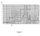
- the figure 5 shows two spectra 10, 11.
- the x-axis 13 represents pixels which correspond in fact to wavelengths and the ordinate axis 14 represents the intensity of the signal in percentage.
- Curve 10 corresponds to the spectrum measured a detector 7 not inclined.
- a spurious peak 12 from the reflections of the beam to be measured between the detector window and the detection surface of the detector appears on the spectrum.
- Curve 11 corresponds to a spectrum measured by an inclined detector 7 of an angle ( ⁇ ) of 20 ° associated with an inclined slit of an angle ( ⁇ ) of 5 °.
- the parasitic peak 12 has almost disappeared without losing spectral resolution or little.
- the bandwidth of the beam measured, when the detector 7 is not inclined, is 1.58 nm. It is 3.98 nm when the detector 7 is inclined and when the slot 3 is not inclined. The bandwidth is 1.68 nm when the detector 7 and the slot 9 are inclined.
- the invention makes it possible to compensate for the spectral resolution losses of an inclined slot spectrograph in a simple and low-cost manner.
Landscapes
- Physics & Mathematics (AREA)
- Spectroscopy & Molecular Physics (AREA)
- General Physics & Mathematics (AREA)
- Spectrometry And Color Measurement (AREA)
- Investigating Or Analysing Materials By Optical Means (AREA)
Description
- La présente invention concerne un spectrographe à fente inclinée.
- Les spectrographes à réseau de l'art antérieur comprennent une source lumineuse, une fente d'entrée, un réseau qui peut être un réseau holographique concave et un détecteur. Les
figures 1 et 2 représentent un exemple de spectrographe à réseau selon l'art antérieur. Lafigure 1 est une représentation du spectrographe à trois dimensions et lafigure 2 correspond à une vue de dessus. - Les réseaux holographiques concaves présentent une surface optique sur laquelle a été inscrit un grand nombre de traits (jusqu'à 6000 traits/mm) servant à diffracter tout faisceau de rayons incidents. Ils fonctionnent préférentiellement en réflexion.
- Les réseaux holographiques concaves sont habituellement corrigés des aberrations.
- Le détecteur peut être un détecteur de type PDA (Photodiode array) ou de type CCD (Charge Coupled Device). Le matériau utilisé pour le détecteur peut être en silicium ou InGaAs par exemple avec une surface qui est très réfléchissante.
- Il est possible d'utiliser un détecteur refroidi. Un tel détecteur refroidi comporte une fenêtre qui protège la surface sensible du détecteur. Cette fenêtre est indispensable afin d'éviter des phénomènes de condensation sur la surface du détecteur.
- Les réflexions multiples produites dans la fenêtre et entre les faces de la fenêtre et la surface du détecteur dégradent considérablement le rapport signal sur bruit, superposant au spectre à mesurer des spectres parasites.
- Afin de réduire l'influence de ces phénomènes sur la performance du spectrographe, il est connu d'utiliser un réseau calculé de telle sorte que le spectre qu'il produit soit incliné. Ainsi, les faisceaux parasites réfléchis sur la surface sensible du détecteur ne retournent pas vers le réseau. On évite ainsi des phénomènes de rediffraction à l'origine de problèmes de lumière parasite qui nuisent à la performance de l'instrument.
- On connaît également la méthode qui consiste à incliner le détecteur autour d'un axe parallèle au spectre, comme illustré sur les
figures 1 et 2 , pour que les réflexions multiples entre le détecteur et les faces de la fenêtre aillent partiellement ou totalement à l'extérieur de la surface sensible du détecteur dans le sens perpendiculaire à la dispersion. En général, cette action altère la résolution spectrale de l'instrument. - Les deux méthodes précédentes, mettant chacune en oeuvre un moyen d'inclinaison, peuvent être utilisées séparément ou conjointement.
- Elles améliorent le bruit de fond du spectrographe. En revanche, elles dégradent considérablement la résolution spectrale de l'appareil.
- Il est aussi connu d'utiliser un filtre sélecteur d'ordre incliné devant le détecteur afin d'éviter une nouvelle contribution à des spectres parasites.
- Des exemples de l'état de la technique sont décrits dans
US5719672 ,DE 196 11 218 ,US 4633078 ,WO 2005095910 etDE 3403372 . - L'objectif de la présente invention est donc de proposer une solution pour compenser les pertes de résolution spectrale du spectrographe.
- A cet effet, l'invention concerne un spectrographe à fente inclinée comprenant les caractéristiques de la revendication 1.
- Dans différents modes de réalisation possibles, la présente invention concerne également les caractéristiques qui ressortiront au cours de la description qui va suivre et qui devront être considérées isolément ou selon toutes leurs combinaisons techniquement possibles :
- le spectrographe à fente inclinée comprend un filtre sélecteur disposé entre le réseau et le détecteur,
- le moyen d'inclinaison apte à éviter des spectres parasites comprend le détecteur qui est un détecteur incliné, ledit détecteur incliné étant incliné d'un angle (α) de façon à ce que le plan de détection (X", Y") dudit détecteur soit incliné d'un angle (α) par rapport au plan image (X', Y') du réseau, et ledit angle (α) étant défini dans le plan (Y", Z"), orthogonal au plan de détection (X", Y"),
- l'angle (α) du détecteur incliné est supérieur à 0° et inférieur à 45°,
- le moyen d'inclinaison apte à éviter des spectres parasites comprend le réseau qui est un réseau calculé de telle sorte que le spectre qu'il produit soit incliné d'un angle (β) par rapport au plan de détection (X", Y") du détecteur,
- le moyen d'inclinaison apte à éviter des spectres parasites comprend :
- le détecteur qui est un détecteur incliné, ledit détecteur incliné étant incliné d'un angle (α) de façon à ce que le plan de détection (X", Y") dudit détecteur soit incliné d'un angle (α) par rapport au plan image (X', Y') du réseau, et ledit angle (α) étant défini dans le plan (Y", Z"), orthogonal au plan de détection (X", Y"), et
- le réseau qui est un réseau calculé de telle sorte que le spectre qu'il produit soit incliné d'un angle (β) par rapport au plan de détection (X", Y") du détecteur.
- L'invention sera décrite plus en détail en référence aux dessins annexés dans lesquels:
- les
figures 1 et 2 sont des représentations à trois dimensions et une vue de dessus respectivement, d'un spectrographe à réseau holographique concave comprenant un détecteur incliné d'un angle (α) selon l'art antérieur ; - les
figures 3 et 4 sont des représentations à trois dimensions et une vue de dessus respectivement, d'un spectrographe à fente inclinée, selon un mode de réalisation de l'invention ; - la
figure 5 montre deux spectres dont un mesuré avec un détecteur non incliné et un autre mesuré avec un détecteur incliné associé à une fente inclinée. - La
figure 1 est une représentation à trois dimensions d'un spectrographe à réseau holographique concave selon l'art antérieur. Lafigure 2 représente la vue de dessus correspondante. - Un tel spectrographe comprend une source lumineuse 1 qui émet un faisceau lumineux se dirigeant vers une fente d'entrée 3 selon une direction 2, parallèle à un axe Z. La fente d'entrée 3 est définie selon le repère (X, Y, Z). La fente d'entrée 3 se trouve dans le plan (X, Y).
- On entend par fente d'entrée 3, une ouverture dans un support ou tout autre moyen bloquant une partie du faisceau lumineux émis par la source lumineuse 1 et transmettant l'autre partie de ce faisceau.
- La source lumineuse 1 illumine quasi uniformément la fente d'entrée 3 directement ou à l'aide d'une optique de couplage.
- Il ressort de la fente d'entrée 3, un faisceau lumineux transmis.
- Le faisceau lumineux transmis par la fente d'entrée 3 est incident sur un réseau 4 qui peut être un réseau holographique concave ou autre. On obtient un faisceau lumineux diffracté et un spectre dans un plan image (X', Y'). Le plan image est défini selon le repère (X', Y', Z') où l'axe Z' est orthogonal au plan image (X', Y').
- La fente d'entrée 3 est rectangulaire et s'étend longitudinalement selon un axe longitudinal Y. Le réseau 4 est un réseau holographique concave. Les traits de ce réseau holographique concave 4 sont courbés et disposés les uns à la suite des autres selon un axe U. La normale W à cet axe d'alignement U et à l'axe Z est parallèle à l'axe longitudinal Y de la fente d'entrée 3. Autrement dit, la normale W est perpendiculaire au plan (U, Z). Le réseau holographique concave 4 présente un axe A normal à l'axe U et passant par le sommet de la surface courbée du réseau.
- Un filtre sélecteur d'ordre peut éventuellement être inséré dans le faisceau après le réseau 4.
- Le faisceau lumineux diffracté par le réseau 4 est détecté par un détecteur 7 qui peut être multicanal. Le détecteur 7 est disposé sur le trajet du faisceau lumineux diffracté par le réseau 4 afin d'intercepter le spectre contenu dans le plan image (X', Y').
- Le détecteur 7 est défini selon un repère (X", Y", Z"). Le plan (X", Y") représente le plan de détection qui est orthogonal à l'axe Z".
- Le détecteur 7 comprend une surface sensible (non représentée) qui se trouve dans le plan de détection (X", Y") du détecteur 7.
- Afin de simplifier le schéma, seule la façade du détecteur 7 est représentée sur les
figures 1 et 2 , et celles qui vont suivre. Cette façade comprend une ouverture de détecteur 12 traversée par le faisceau lumineux diffracté avant qu'il n'arrive sur la surface sensible du détecteur 7. - Le spectrographe à réseau holographique concave peut comprendre des moyens optiques tels des miroirs pour réfléchir et focaliser le faisceau lumineux transmis par la fente 3, le faisceau diffracté et éventuellement le faisceau dispersé.
- Le détecteur 7 comprend souvent une fenêtre 6 à travers laquelle est transmis le faisceau lumineux diffracté par le réseau 4.
- Une partie du faisceau lumineux diffracté génère des réflexions multiples sur la fenêtre 6 ou entre celle-ci et la surface sensible du détecteur 7.
- Pour éliminer ces réflexions, il est connu, comme dit plus haut, d'utiliser au moins un moyen d'inclinaison apte à éviter que des spectres parasites se superposent au spectre à mesurer.
- Ces moyens d'inclinaison de l'art antérieur consistent à incliner soit le spectre à mesurer, c'est-à-dire le plan image (X', Y') du réseau 8, par rapport au plan de détection (X", Y") du détecteur 7, soit le plan de détection (X", Y") du détecteur 7.
- Le moyen d'inclinaison peut comprendre un détecteur incliné 7, comme représenté sur les
figures 1 et 2 . - Le détecteur incliné 7 est incliné de façon à ce que le plan de détection (X", Y") de ce dernier soit incliné d'un angle (α) par rapport au plan image (X', Y') du réseau. L'angle (α) est défini dans le plan (Y", Z"), orthogonal au plan de détection (X", Y").
- On entend par l'inclinaison du détecteur, l'inclinaison de la surface sensible du détecteur également.
- Sur la
figure 1 , l'axe Z" est incliné d'un angle (α) par rapport à l'axe Z' et l'axe Y" est incliné d'un angle (α) par rapport à l'axe Y'. - Cette inclinaison d'un angle (α) évite que les faisceaux réfléchis reviennent vers le réseau 4.
- De même, il est possible d'utiliser, comme moyen d'inclinaison, un réseau calculé 8 de telle sorte que le spectre qu'il produit soit incliné d'un angle (β) par rapport au plan de détection (X", Y") du détecteur 7. Le spectre produit est contenu dans le plan image (X', Y') du réseau calculé 8.
- Ces deux moyens d'inclinaison peuvent être utilisés séparément ou conjointement.
- Ils améliorent le bruit de fond du spectrographe. En revanche, ils dégradent considérablement la résolution spectrale de l'appareil.
- Pour résoudre ce problème, l'invention propose, comme représenté sur les
figures 3 et 4 , un spectrographe à fente inclinée comprenant un moyen de compensation apte à compenser les pertes de résolution spectrale générées par les moyens d'inclinaison. - Dans cet exemple, les deux moyens d'inclinaison sont utilisés conjointement.
- Les
figures 3 et 4 correspondent à une représentation à trois dimensions et à une vue de dessus, respectivement, d'un spectrographe à fente inclinée. - Pour faciliter la compréhension de la
figure 3 , seul l'angle (α) est représenté. - La
figure 4 montre seulement l'angle (β) car l'angle (α) n'est pas visible dans le plan de la feuille. - Le moyen de compensation des pertes de résolution spectrale comprend une fente d'entrée inclinée 9 disposée entre la source lumineuse 1 et le réseau calculé 8.
- La fente d'entrée inclinée 9 est inclinée dans le plan (X, Y) perpendiculaire à la direction 2 du faisceau lumineux émis par la source lumineuse 1. La fente d'entrée inclinée 9 subie une rotation autour de l'axe Z.
- La fente d'entrée inclinée 9 est en fait inclinée par rapport aux traits du réseau 4 qui sont alignés suivant un axe d'alignement U.
- Plus précisément, l'axe longitudinal Y de la fente d'entrée inclinée 9 est incliné d'un angle (θ) par rapport à la normale W au plan (U, Z).
- Dit autrement, la fente d'entrée inclinée 9 est inclinée d'un angle (θ) par rapport à sa position initiale, représentée sur la
figure 1 , où elle n'est pas inclinée. L'angle (θ) est supérieur à 0° et inférieur à 90°. - Encore dit autrement, si on projette les traits du réseau sur un plan de projection parallèle à l'axe d'alignement U, les traits projetés sont alignés également selon l'axe d'alignement U et l'axe longitudinal Y de la fente d'entrée inclinée 9 est incliné de l'angle (θ) par rapport aux traits projetés dans le plan de projection.
- Le détecteur incliné 7 est incliné d'un angle (α) de façon à ce que le plan de détection (X", Y") du détecteur 7 soit incliné d'un angle (α) par rapport au plan image (X', Y') du réseau. Sur la
figure 3 , le détecteur 7 est incliné vers le bas. Il peut également être incliné vers le haut. - L'angle (α) du détecteur incliné (7) est supérieur à 0° et inférieur à 45°.
- La fente d'entrée inclinée 9 permet de compenser les pertes de résolution introduites par le détecteur incliné d'un angle (α) 7 et le spectre incliné d'un angle (β).
- Dans d'autres modes de réalisation possibles, la fente d'entrée inclinée 9 peut être utilisée lorsque les moyens d'inclinaison, précédemment cités, sont utilisés séparément.
- La
figure 5 montre deux spectres 10, 11. L'axe des abscisses 13 représente des pixels qui correspondent en fait à des longueurs d'onde et l'axe des ordonnées 14 représente l'intensité du signal en pourcentage. - La courbe 10 correspond au spectre mesuré un détecteur 7 non incliné.
- Il apparaît sur le spectre 10 un pic parasite 12 provenant des réflexions du faisceau à mesurer entre la fenêtre du détecteur et la surface de détection du détecteur.
- La courbe 11 correspond à un spectre mesuré par un détecteur incliné 7 d'un angle (α) de 20° associé à une fente inclinée d'un angle (θ) de 5°. Le pic parasite 12 a quasiment disparu sans perdre en résolution spectrale ou peu.
- Les résultats ci-dessous sont donnés pour une longueur d'onde de 800 nm.
- La bande passante du faisceau mesuré, lorsque le détecteur 7 n'est pas incliné, est de 1,58 nm. Elle est de 3,98 nm lorsque le détecteur 7 est incliné et lorsque la fente 3 n'est pas inclinée. La bande passante est de 1,68 nm lorsque le détecteur 7 et la fente 9 sont inclinés.
- Ainsi, l'invention permet de compenser les pertes de résolution spectrale d'un spectrographe à fente inclinée de manière simple et à faible coût.
Claims (6)
- Spectrographe à fente inclinée comprenant :- une source lumineuse (1) apte à émettre un faisceau lumineux suivant une direction (2) parallèle à un axe (Z),- une fente d'entrée (3, 9) apte à transmettre une partie du faisceau lumineux émis par la source lumineuse (1) et à générer un faisceau lumineux transmis, ladite fente d'entrée étant de forme rectangulaire et s'étendant selon un axe longitudinal (Y),- un réseau (4, 8) comprenant des traits disposés les uns à la suite des autres suivant un axe d'alignement (U) et perpendiculaires au plan (U, Z) du spectrographe, ledit réseau (4, 8) étant apte à diffracter le faisceau lumineux transmis par la fente d'entrée (3, 9) et à générer un faisceau lumineux diffracté et un spectre dans un plan image (X', Y'),- un détecteur (7) apte à détecter le faisceau lumineux diffracté par le réseau (4, 8), ledit détecteur (7) comprenant une fenêtre (6) à travers laquelle est transmis le faisceau lumineux diffracté par le réseau (4, 8), une partie du faisceau lumineux diffracté générant des réflexions sur la fenêtre (6) ou entre celle-ci et la surface sensible du détecteur (7) contenue dans un plan de détection (X", Y"),- au moins un moyen d'inclinaison relative du plan image (X',Y') du spectre diffracté par rapport au plan de détection (X", Y") du détecteur apte à éviter des spectres parasites,caractérisé en ce qu'il comprend :- un moyen de compensation apte à compenser les pertes de résolution spectrale générées par les moyens d'inclinaison, ledit moyen de compensation comprenant la fente d'entrée (3, 9) qui est une fente d'entrée inclinée (9) disposée entre la source lumineuse (1) et le réseau (4, 8) et un moyen de rotation de la fente d'entrée par rapport à un axe perpendiculaire au plan de la fente, ladite fente d'entrée inclinée (9) étant inclinée autour de l'axe (Z) dans un plan (X, Y) perpendiculaire à la direction (2) du faisceau lumineux émis par la source lumineuse (1), l'axe longitudinal (Y) de la fente d'entrée inclinée (9) étant incliné d'un angle (θ) par rapport à la normale (W) au plan (U, Z) de dispersion du réseau , l'angle (θ) étant supérieur à 0 ° et inférieur à 90°.
- Spectrographe à fente inclinée selon la revendication 1, caractérisé en ce qu'il comprend un filtre sélecteur disposé entre le réseau (4, 8) et le détecteur (7).
- Spectrographe à fente inclinée selon l'une quelconque des revendications 1 ou 2, caractérisé en ce que le moyen d'inclinaison apte à éviter des spectres parasites comprend le détecteur (7) qui est un détecteur incliné, ledit détecteur incliné étant incliné d'un angle (α) de façon à ce que le plan de détection (X", Y") dudit détecteur soit incliné d'un angle (α) par rapport au plan image (X', Y') du réseau, et ledit angle (α) étant défini dans le plan (Y", Z"), orthogonal au plan de détection (X", Y").
- Spectrographe à fente inclinée selon la revendication 3, caractérisé en ce que l'angle (α) du détecteur incliné (7) est supérieur à 0° et inférieur à 45°.
- Spectrographe à fente inclinée selon l'une quelconque des revendications 1 à 4, caractérisé en ce que le moyen d'inclinaison apte à éviter des spectres parasites comprend le réseau (4, 8) qui est un réseau calculé (8) de telle sorte que le spectre qu'il produit soit incliné d'un angle (β) par rapport au plan de détection (X", Y") du détecteur (7).
- Spectrographe à fente inclinée selon la revendication 1, caractérisé en ce que le moyen d'inclinaison apte à éviter des spectres parasites comprend : - le détecteur (7) qui est un détecteur incliné, ledit détecteur incliné étant incliné d'un angle (α) de façon à ce que le plan de détection (X", Y") dudit détecteur soit incliné d'un angle (α) par rapport au plan image (X', Y') du réseau, et ledit angle (α) étant défini dans le plan (Y", Z"), orthogonal au plan de détection (X", Y"), et - le réseau (4, 8) qui est un réseau calculé (8) de telle sorte que le spectre qu'il produit soit incliné d'un angle (β) par rapport au plan de détection (X", Y") du détecteur (7).
Applications Claiming Priority (2)
| Application Number | Priority Date | Filing Date | Title |
|---|---|---|---|
| FR0753565A FR2913113B1 (fr) | 2007-02-28 | 2007-02-28 | Spectrographe a fente inclinee. |
| PCT/FR2008/050334 WO2008119906A1 (fr) | 2007-02-28 | 2008-02-27 | Spectrographe a fente inclinee |
Publications (2)
| Publication Number | Publication Date |
|---|---|
| EP2126527A1 EP2126527A1 (fr) | 2009-12-02 |
| EP2126527B1 true EP2126527B1 (fr) | 2013-09-18 |
Family
ID=38476861
Family Applications (1)
| Application Number | Title | Priority Date | Filing Date |
|---|---|---|---|
| EP08762169.4A Active EP2126527B1 (fr) | 2007-02-28 | 2008-02-27 | Spectrographe a fente inclinee |
Country Status (6)
| Country | Link |
|---|---|
| US (1) | US8284397B2 (fr) |
| EP (1) | EP2126527B1 (fr) |
| JP (1) | JP5269814B2 (fr) |
| DK (1) | DK2126527T3 (fr) |
| FR (1) | FR2913113B1 (fr) |
| WO (1) | WO2008119906A1 (fr) |
Families Citing this family (9)
| Publication number | Priority date | Publication date | Assignee | Title |
|---|---|---|---|---|
| US8430314B1 (en) * | 2011-11-14 | 2013-04-30 | Symbol Technologies, Inc. | Apparatus for and method of aligning non-rotationally symmetrical imaging lens aperture with an imaging sensor in an imaging reader |
| JP2013124990A (ja) * | 2011-12-15 | 2013-06-24 | Canon Inc | 画像処理装置および画像処理方法 |
| CN102538962B (zh) * | 2012-01-19 | 2015-11-18 | 杭州远方光电信息股份有限公司 | 一种低杂散光多色仪 |
| JP5929504B2 (ja) * | 2012-05-23 | 2016-06-08 | 株式会社島津製作所 | 分光測定器 |
| RU2567448C1 (ru) * | 2014-07-30 | 2015-11-10 | Открытое акционерное общество "Красногорский завод им. С.А. Зверева" | Зеркальный спектрометр |
| US10866140B2 (en) | 2017-04-20 | 2020-12-15 | Shimadzu Corporation | Spectrophotometer |
| US10386232B2 (en) | 2017-12-15 | 2019-08-20 | Horiba Instruments Incorporated | Compact spectroscopic optical instrument |
| CN109682471B (zh) * | 2019-01-25 | 2024-06-11 | 奥谱天成(厦门)科技有限公司 | 一种高精多维度光谱仪探测器调节结构 |
| US20240167944A1 (en) * | 2022-11-17 | 2024-05-23 | Onelight Sensing, Llc | Multi-Order Spectroscopy |
Family Cites Families (5)
| Publication number | Priority date | Publication date | Assignee | Title |
|---|---|---|---|---|
| US4633078A (en) * | 1985-07-23 | 1986-12-30 | The Perkin-Elmer Corporation | Optical interference eliminator |
| US5644396A (en) * | 1995-06-20 | 1997-07-01 | Hewlett-Packard Company | Spectrograph with low focal ratio |
| US5719672A (en) * | 1996-09-26 | 1998-02-17 | Varian Associates, Inc. | Echelle spectrometer with a shaped oriented slit |
| JP2001108523A (ja) * | 1999-10-14 | 2001-04-20 | Matsushita Electric Ind Co Ltd | 分光測定装置 |
| RU2262086C1 (ru) * | 2004-04-01 | 2005-10-10 | Лившиц Александр Маркович | Способ измерения спектра излучения, спектрометр и малогабаритный спектрометр |
-
2007
- 2007-02-28 FR FR0753565A patent/FR2913113B1/fr active Active
-
2008
- 2008-02-27 EP EP08762169.4A patent/EP2126527B1/fr active Active
- 2008-02-27 WO PCT/FR2008/050334 patent/WO2008119906A1/fr not_active Ceased
- 2008-02-27 DK DK08762169.4T patent/DK2126527T3/da active
- 2008-02-27 US US12/527,943 patent/US8284397B2/en active Active
- 2008-02-27 JP JP2009551249A patent/JP5269814B2/ja active Active
Also Published As
| Publication number | Publication date |
|---|---|
| US8284397B2 (en) | 2012-10-09 |
| FR2913113A1 (fr) | 2008-08-29 |
| EP2126527A1 (fr) | 2009-12-02 |
| FR2913113B1 (fr) | 2009-06-05 |
| DK2126527T3 (da) | 2013-12-09 |
| WO2008119906A1 (fr) | 2008-10-09 |
| JP5269814B2 (ja) | 2013-08-21 |
| US20100118299A1 (en) | 2010-05-13 |
| JP2010520445A (ja) | 2010-06-10 |
Similar Documents
| Publication | Publication Date | Title |
|---|---|---|
| WO2008119906A1 (fr) | Spectrographe a fente inclinee | |
| EP1965183A1 (fr) | Spectrographe à fenêtre de détecteur inclinée | |
| EP2502038B1 (fr) | Spectrometre optique a reseau de diffraction concave | |
| EP0021887B1 (fr) | Dispositif optoélectrique de détection, notamment de rayonnement laser | |
| WO2014087081A1 (fr) | Spectromètre pour l'analyse du spectre d'un faisceau lumineux | |
| EP4016053A1 (fr) | Composant optique pour un dispositif d'imagerie interférométrique | |
| EP3030867B1 (fr) | Spectrometre a plusieurs reseaux de diffraction. | |
| CA2220940C (fr) | Dispositif pour determiner les defauts de phase d'ondes electromagnetiques | |
| FR2803033A1 (fr) | Monochromateur et procede spectrometrique | |
| EP3913395B1 (fr) | Detecteur ameliore avec elements de deviation pour imagerie coherente | |
| EP3824273A1 (fr) | Dispositif de mesure d'un flux de matiere par absorption de lumiere, et procede de mesure correspondant | |
| WO2009127794A1 (fr) | Spectrometre compact a echantillonage bidimensionnel | |
| EP0104114B1 (fr) | Dispositif viseur à miroir holographique, et procédé de fabrication du miroir | |
| WO2011098726A1 (fr) | Spectrographe compact a large bande spectrale comprenant une pluralite de reseaux de diffraction | |
| EP2473824B1 (fr) | Interféromètre à compensation de champ | |
| FR2809809A1 (fr) | Monochromateur et procede spectrometrique | |
| FR2857746A1 (fr) | Spectrometre optique miniaturise a haute resolution | |
| EP1141668B1 (fr) | Dispositif a rejet spectral de formation d'une image sur un capteur optique | |
| EP3850339B1 (fr) | Capteur de gaz compact | |
| WO1993016361A1 (fr) | Dispositif de spectrographie | |
| FR3059156B1 (fr) | Module de detection optique | |
| EP1793212B1 (fr) | Spectrophotometre à la large fente d'entrée | |
| FR2718588A1 (fr) | Dispositif d'égalisation, en fonction de la longueur d'onde, d'un gain appliqué à un signal optique. | |
| FR2563015A1 (fr) | Appareil de distribution et de detection d'energie rayonnante |
Legal Events
| Date | Code | Title | Description |
|---|---|---|---|
| PUAI | Public reference made under article 153(3) epc to a published international application that has entered the european phase |
Free format text: ORIGINAL CODE: 0009012 |
|
| 17P | Request for examination filed |
Effective date: 20090826 |
|
| AK | Designated contracting states |
Kind code of ref document: A1 Designated state(s): AT BE BG CH CY CZ DE DK EE ES FI FR GB GR HR HU IE IS IT LI LT LU LV MC MT NL NO PL PT RO SE SI SK TR |
|
| 17Q | First examination report despatched |
Effective date: 20100118 |
|
| RIN1 | Information on inventor provided before grant (corrected) |
Inventor name: CORDE, PIERRE-ANDRE Inventor name: MILLET, VIVIANE Inventor name: THEVENON, ALAIN |
|
| DAX | Request for extension of the european patent (deleted) | ||
| GRAP | Despatch of communication of intention to grant a patent |
Free format text: ORIGINAL CODE: EPIDOSNIGR1 |
|
| INTG | Intention to grant announced |
Effective date: 20130524 |
|
| RIN1 | Information on inventor provided before grant (corrected) |
Inventor name: THEVENON, ALAIN Inventor name: CORDE, PIERRE-ANDRE Inventor name: MILLET, VIVIANE |
|
| GRAS | Grant fee paid |
Free format text: ORIGINAL CODE: EPIDOSNIGR3 |
|
| GRAA | (expected) grant |
Free format text: ORIGINAL CODE: 0009210 |
|
| AK | Designated contracting states |
Kind code of ref document: B1 Designated state(s): AT BE BG CH CY CZ DE DK EE ES FI FR GB GR HR HU IE IS IT LI LT LU LV MC MT NL NO PL PT RO SE SI SK TR |
|
| REG | Reference to a national code |
Ref country code: GB Ref legal event code: FG4D Free format text: NOT ENGLISH |
|
| REG | Reference to a national code |
Ref country code: CH Ref legal event code: EP |
|
| REG | Reference to a national code |
Ref country code: IE Ref legal event code: FG4D Free format text: LANGUAGE OF EP DOCUMENT: FRENCH |
|
| REG | Reference to a national code |
Ref country code: AT Ref legal event code: REF Ref document number: 633019 Country of ref document: AT Kind code of ref document: T Effective date: 20131015 |
|
| REG | Reference to a national code |
Ref country code: DE Ref legal event code: R096 Ref document number: 602008027654 Country of ref document: DE Effective date: 20131114 |
|
| REG | Reference to a national code |
Ref country code: CH Ref legal event code: NV Representative=s name: KIRKER AND CIE S.A., CH |
|
| REG | Reference to a national code |
Ref country code: DK Ref legal event code: T3 Effective date: 20131204 |
|
| REG | Reference to a national code |
Ref country code: SE Ref legal event code: TRGR |
|
| REG | Reference to a national code |
Ref country code: NL Ref legal event code: T3 |
|
| PG25 | Lapsed in a contracting state [announced via postgrant information from national office to epo] |
Ref country code: CY Free format text: LAPSE BECAUSE OF FAILURE TO SUBMIT A TRANSLATION OF THE DESCRIPTION OR TO PAY THE FEE WITHIN THE PRESCRIBED TIME-LIMIT Effective date: 20130814 Ref country code: NO Free format text: LAPSE BECAUSE OF FAILURE TO SUBMIT A TRANSLATION OF THE DESCRIPTION OR TO PAY THE FEE WITHIN THE PRESCRIBED TIME-LIMIT Effective date: 20131218 Ref country code: HR Free format text: LAPSE BECAUSE OF FAILURE TO SUBMIT A TRANSLATION OF THE DESCRIPTION OR TO PAY THE FEE WITHIN THE PRESCRIBED TIME-LIMIT Effective date: 20130918 Ref country code: LT Free format text: LAPSE BECAUSE OF FAILURE TO SUBMIT A TRANSLATION OF THE DESCRIPTION OR TO PAY THE FEE WITHIN THE PRESCRIBED TIME-LIMIT Effective date: 20130918 |
|
| REG | Reference to a national code |
Ref country code: LT Ref legal event code: MG4D |
|
| PG25 | Lapsed in a contracting state [announced via postgrant information from national office to epo] |
Ref country code: LV Free format text: LAPSE BECAUSE OF FAILURE TO SUBMIT A TRANSLATION OF THE DESCRIPTION OR TO PAY THE FEE WITHIN THE PRESCRIBED TIME-LIMIT Effective date: 20130918 Ref country code: SI Free format text: LAPSE BECAUSE OF FAILURE TO SUBMIT A TRANSLATION OF THE DESCRIPTION OR TO PAY THE FEE WITHIN THE PRESCRIBED TIME-LIMIT Effective date: 20130918 Ref country code: GR Free format text: LAPSE BECAUSE OF FAILURE TO SUBMIT A TRANSLATION OF THE DESCRIPTION OR TO PAY THE FEE WITHIN THE PRESCRIBED TIME-LIMIT Effective date: 20131219 |
|
| PG25 | Lapsed in a contracting state [announced via postgrant information from national office to epo] |
Ref country code: CY Free format text: LAPSE BECAUSE OF FAILURE TO SUBMIT A TRANSLATION OF THE DESCRIPTION OR TO PAY THE FEE WITHIN THE PRESCRIBED TIME-LIMIT Effective date: 20130918 |
|
| PG25 | Lapsed in a contracting state [announced via postgrant information from national office to epo] |
Ref country code: SK Free format text: LAPSE BECAUSE OF FAILURE TO SUBMIT A TRANSLATION OF THE DESCRIPTION OR TO PAY THE FEE WITHIN THE PRESCRIBED TIME-LIMIT Effective date: 20130918 Ref country code: CZ Free format text: LAPSE BECAUSE OF FAILURE TO SUBMIT A TRANSLATION OF THE DESCRIPTION OR TO PAY THE FEE WITHIN THE PRESCRIBED TIME-LIMIT Effective date: 20130918 Ref country code: EE Free format text: LAPSE BECAUSE OF FAILURE TO SUBMIT A TRANSLATION OF THE DESCRIPTION OR TO PAY THE FEE WITHIN THE PRESCRIBED TIME-LIMIT Effective date: 20130918 Ref country code: RO Free format text: LAPSE BECAUSE OF FAILURE TO SUBMIT A TRANSLATION OF THE DESCRIPTION OR TO PAY THE FEE WITHIN THE PRESCRIBED TIME-LIMIT Effective date: 20130918 Ref country code: IS Free format text: LAPSE BECAUSE OF FAILURE TO SUBMIT A TRANSLATION OF THE DESCRIPTION OR TO PAY THE FEE WITHIN THE PRESCRIBED TIME-LIMIT Effective date: 20140118 |
|
| PG25 | Lapsed in a contracting state [announced via postgrant information from national office to epo] |
Ref country code: PL Free format text: LAPSE BECAUSE OF FAILURE TO SUBMIT A TRANSLATION OF THE DESCRIPTION OR TO PAY THE FEE WITHIN THE PRESCRIBED TIME-LIMIT Effective date: 20130918 Ref country code: ES Free format text: LAPSE BECAUSE OF FAILURE TO SUBMIT A TRANSLATION OF THE DESCRIPTION OR TO PAY THE FEE WITHIN THE PRESCRIBED TIME-LIMIT Effective date: 20130918 |
|
| REG | Reference to a national code |
Ref country code: DE Ref legal event code: R097 Ref document number: 602008027654 Country of ref document: DE |
|
| PG25 | Lapsed in a contracting state [announced via postgrant information from national office to epo] |
Ref country code: PT Free format text: LAPSE BECAUSE OF FAILURE TO SUBMIT A TRANSLATION OF THE DESCRIPTION OR TO PAY THE FEE WITHIN THE PRESCRIBED TIME-LIMIT Effective date: 20140120 |
|
| PLBE | No opposition filed within time limit |
Free format text: ORIGINAL CODE: 0009261 |
|
| STAA | Information on the status of an ep patent application or granted ep patent |
Free format text: STATUS: NO OPPOSITION FILED WITHIN TIME LIMIT |
|
| 26N | No opposition filed |
Effective date: 20140619 |
|
| PG25 | Lapsed in a contracting state [announced via postgrant information from national office to epo] |
Ref country code: IT Free format text: LAPSE BECAUSE OF FAILURE TO SUBMIT A TRANSLATION OF THE DESCRIPTION OR TO PAY THE FEE WITHIN THE PRESCRIBED TIME-LIMIT Effective date: 20130918 |
|
| BERE | Be: lapsed |
Owner name: HORIBA JOBIN YVON S.A.S. Effective date: 20140228 |
|
| PG25 | Lapsed in a contracting state [announced via postgrant information from national office to epo] |
Ref country code: MC Free format text: LAPSE BECAUSE OF FAILURE TO SUBMIT A TRANSLATION OF THE DESCRIPTION OR TO PAY THE FEE WITHIN THE PRESCRIBED TIME-LIMIT Effective date: 20130918 Ref country code: LU Free format text: LAPSE BECAUSE OF FAILURE TO SUBMIT A TRANSLATION OF THE DESCRIPTION OR TO PAY THE FEE WITHIN THE PRESCRIBED TIME-LIMIT Effective date: 20140227 |
|
| REG | Reference to a national code |
Ref country code: DE Ref legal event code: R097 Ref document number: 602008027654 Country of ref document: DE Effective date: 20140619 |
|
| REG | Reference to a national code |
Ref country code: IE Ref legal event code: MM4A |
|
| PG25 | Lapsed in a contracting state [announced via postgrant information from national office to epo] |
Ref country code: BE Free format text: LAPSE BECAUSE OF NON-PAYMENT OF DUE FEES Effective date: 20140228 Ref country code: IE Free format text: LAPSE BECAUSE OF NON-PAYMENT OF DUE FEES Effective date: 20140227 |
|
| REG | Reference to a national code |
Ref country code: FR Ref legal event code: PLFP Year of fee payment: 9 |
|
| PG25 | Lapsed in a contracting state [announced via postgrant information from national office to epo] |
Ref country code: MT Free format text: LAPSE BECAUSE OF FAILURE TO SUBMIT A TRANSLATION OF THE DESCRIPTION OR TO PAY THE FEE WITHIN THE PRESCRIBED TIME-LIMIT Effective date: 20130918 |
|
| PG25 | Lapsed in a contracting state [announced via postgrant information from national office to epo] |
Ref country code: BG Free format text: LAPSE BECAUSE OF FAILURE TO SUBMIT A TRANSLATION OF THE DESCRIPTION OR TO PAY THE FEE WITHIN THE PRESCRIBED TIME-LIMIT Effective date: 20130918 |
|
| PG25 | Lapsed in a contracting state [announced via postgrant information from national office to epo] |
Ref country code: TR Free format text: LAPSE BECAUSE OF FAILURE TO SUBMIT A TRANSLATION OF THE DESCRIPTION OR TO PAY THE FEE WITHIN THE PRESCRIBED TIME-LIMIT Effective date: 20130918 Ref country code: HU Free format text: LAPSE BECAUSE OF FAILURE TO SUBMIT A TRANSLATION OF THE DESCRIPTION OR TO PAY THE FEE WITHIN THE PRESCRIBED TIME-LIMIT; INVALID AB INITIO Effective date: 20080227 |
|
| REG | Reference to a national code |
Ref country code: FR Ref legal event code: PLFP Year of fee payment: 10 |
|
| REG | Reference to a national code |
Ref country code: FR Ref legal event code: PLFP Year of fee payment: 11 |
|
| P01 | Opt-out of the competence of the unified patent court (upc) registered |
Effective date: 20230524 |
|
| PGFP | Annual fee paid to national office [announced via postgrant information from national office to epo] |
Ref country code: DK Payment date: 20241205 Year of fee payment: 18 |
|
| PGFP | Annual fee paid to national office [announced via postgrant information from national office to epo] |
Ref country code: FI Payment date: 20241204 Year of fee payment: 18 |
|
| PGFP | Annual fee paid to national office [announced via postgrant information from national office to epo] |
Ref country code: GB Payment date: 20241203 Year of fee payment: 18 |
|
| PGFP | Annual fee paid to national office [announced via postgrant information from national office to epo] |
Ref country code: SE Payment date: 20241205 Year of fee payment: 18 |
|
| PGFP | Annual fee paid to national office [announced via postgrant information from national office to epo] |
Ref country code: NL Payment date: 20250218 Year of fee payment: 18 |
|
| PGFP | Annual fee paid to national office [announced via postgrant information from national office to epo] |
Ref country code: AT Payment date: 20241204 Year of fee payment: 18 Ref country code: CH Payment date: 20250301 Year of fee payment: 18 |
|
| PGFP | Annual fee paid to national office [announced via postgrant information from national office to epo] |
Ref country code: FR Payment date: 20251202 Year of fee payment: 19 |
|
| PGFP | Annual fee paid to national office [announced via postgrant information from national office to epo] |
Ref country code: DE Payment date: 20251204 Year of fee payment: 19 |