EP2126366B1 - Deckenventilator für industriegebäude - Google Patents
Deckenventilator für industriegebäude Download PDFInfo
- Publication number
- EP2126366B1 EP2126366B1 EP08728279A EP08728279A EP2126366B1 EP 2126366 B1 EP2126366 B1 EP 2126366B1 EP 08728279 A EP08728279 A EP 08728279A EP 08728279 A EP08728279 A EP 08728279A EP 2126366 B1 EP2126366 B1 EP 2126366B1
- Authority
- EP
- European Patent Office
- Prior art keywords
- fan
- hub
- ceiling fan
- hanger
- fan blades
- Prior art date
- Legal status (The legal status is an assumption and is not a legal conclusion. Google has not performed a legal analysis and makes no representation as to the accuracy of the status listed.)
- Active
Links
Images

Classifications
-
- F—MECHANICAL ENGINEERING; LIGHTING; HEATING; WEAPONS; BLASTING
- F04—POSITIVE - DISPLACEMENT MACHINES FOR LIQUIDS; PUMPS FOR LIQUIDS OR ELASTIC FLUIDS
- F04D—NON-POSITIVE-DISPLACEMENT PUMPS
- F04D25/00—Pumping installations or systems
- F04D25/02—Units comprising pumps and their driving means
- F04D25/08—Units comprising pumps and their driving means the working fluid being air, e.g. for ventilation
- F04D25/088—Ceiling fans
-
- F—MECHANICAL ENGINEERING; LIGHTING; HEATING; WEAPONS; BLASTING
- F04—POSITIVE - DISPLACEMENT MACHINES FOR LIQUIDS; PUMPS FOR LIQUIDS OR ELASTIC FLUIDS
- F04D—NON-POSITIVE-DISPLACEMENT PUMPS
- F04D29/00—Details, component parts, or accessories
- F04D29/26—Rotors specially for elastic fluids
- F04D29/32—Rotors specially for elastic fluids for axial flow pumps
- F04D29/325—Rotors specially for elastic fluids for axial flow pumps for axial flow fans
- F04D29/329—Details of the hub
-
- F—MECHANICAL ENGINEERING; LIGHTING; HEATING; WEAPONS; BLASTING
- F04—POSITIVE - DISPLACEMENT MACHINES FOR LIQUIDS; PUMPS FOR LIQUIDS OR ELASTIC FLUIDS
- F04D—NON-POSITIVE-DISPLACEMENT PUMPS
- F04D29/00—Details, component parts, or accessories
- F04D29/26—Rotors specially for elastic fluids
- F04D29/32—Rotors specially for elastic fluids for axial flow pumps
- F04D29/34—Blade mountings
-
- F—MECHANICAL ENGINEERING; LIGHTING; HEATING; WEAPONS; BLASTING
- F04—POSITIVE - DISPLACEMENT MACHINES FOR LIQUIDS; PUMPS FOR LIQUIDS OR ELASTIC FLUIDS
- F04D—NON-POSITIVE-DISPLACEMENT PUMPS
- F04D29/00—Details, component parts, or accessories
- F04D29/60—Mounting; Assembling; Disassembling
- F04D29/601—Mounting; Assembling; Disassembling specially adapted for elastic fluid pumps
-
- F—MECHANICAL ENGINEERING; LIGHTING; HEATING; WEAPONS; BLASTING
- F04—POSITIVE - DISPLACEMENT MACHINES FOR LIQUIDS; PUMPS FOR LIQUIDS OR ELASTIC FLUIDS
- F04D—NON-POSITIVE-DISPLACEMENT PUMPS
- F04D29/00—Details, component parts, or accessories
- F04D29/60—Mounting; Assembling; Disassembling
- F04D29/64—Mounting; Assembling; Disassembling of axial pumps
- F04D29/644—Mounting; Assembling; Disassembling of axial pumps especially adapted for elastic fluid pumps
- F04D29/646—Mounting or removal of fans
-
- F—MECHANICAL ENGINEERING; LIGHTING; HEATING; WEAPONS; BLASTING
- F24—HEATING; RANGES; VENTILATING
- F24F—AIR-CONDITIONING; AIR-HUMIDIFICATION; VENTILATION; USE OF AIR CURRENTS FOR SCREENING
- F24F7/00—Ventilation
- F24F7/007—Ventilation with forced flow
Definitions
- the present disclosure generally pertains to ceiling fans and more specifically to industrial ceiling fans.
- An area can be ventilated by a large number of small fans or a fewer number of large fans. Either option has its advantages and disadvantages. Smaller fans can be easier to install between rafters, sprinkler heads, hanging lights and other obstacles found in some buildings. Small fans might also be strategically located to focus the ventilation where it is most needed. In buildings with high ceilings, however, small fans might not have the capacity to discharge air at a volume that can effectively reach the area near the floor where the occupants could appreciate the airflow, thus small fans might be almost worthless in some cases.
- a fan which has a fan housing, a motor and at least one fan blade.
- the fan blade is integrally formed at the fan housing.
- US 2002/0085919 A1 pertains to a ceiling fan lifting and lowering apparatus.
- a fan blade-mounting system which has resilient mounts.
- the resilient mounts are utilized in a blade root member to effectively pivotally couple blades to a hub of a fan.
- US 2004/0253112 A1 pertains to ceiling fan with an inside-out motor.
- the stator of the motor is mounted to a downrod at which the ceiling fan is mounted to a ceiling.
- a rotor is rotatably mounted about the stator.
- vanes mounted to the rotor are arranged, such that ambient air is directed into the rotor during operation of the fan, in order to cool the motor.
- the invention provides a ceiling fan mountable to an overhead structure in accordance with independent claim 1.
- a ceiling fan is suspended from an adjustable length bar.
- a ceiling fan has a redundant combination of weld fillets and mechanical fasteners that helps ensure that the motor remains coupled to the hanger.
- the fan includes a safety ring that inhibits complete separation of the fan hub from the drive shaft and which serves to couple the blade support arms together.
- a ceiling fan has blade tips that are tilted upward.
- a resilient bushing helps couple the fan blades to the hub, wherein the bushing helps minimizes stress at the root of the fan blades.
- the resilient bushing allows the blades to deflect upward as the speed of the fan increases.
- the fan provides an airflow thrust with a reaction force that supports most of the blades weight.
- the fan blades are at least five feet long.
- the number of fan blades is no more than six, and the blades are relatively light compared to the thrust they exert.
- the fan blades are tapered and twisted along their length, and the blades angle of attack is greater near the root of the fan blade than near its tip to more evenly distribute the airflow across the full diameter of the fan.
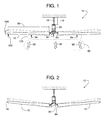
- a ceiling fan 10, illustrated in Figures 1 - 5 includes various features that make fan 10 particularly suited for ventilating large open areas in a building such as in a factory or warehouse.
- Fan 10 for instance, has fan blades 12 that can be five to twelve feet long (or longer) to ventilate a broad area below the fan; fan blades 12 can be tilted lengthwise with a blade tip 14 raised so that fan 10 can cover an even broader area; each fan blade 12 has a shape that varies along its length to promote airflow underneath the full diameter of the fan; a hanger 16 has an adjustable length 18 so that fan 10 can be installed at an elevation where fan blades 12 can avoid pipes, hanging light fixtures, overhead beams and various other obstacles often found in industrial buildings; a resilient connector 20 ( Figs. 3 and 4 ) provides fan blades 12 with strain relief and additional flexibility; and fan 10 includes a bracket assembly 22 with redundant or backup connections for safety.
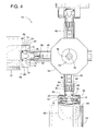
- fan 10 To rotate fan blades 12, fan 10 includes an electric motor 24 comprising a rotor 26, a stator 28, and a speed-reducing gearbox 30. To keep the physical size and weight of motor 24 to a minimum (e.g., approximately 98 lbs) while providing sufficient horsepower (e.g., about 2 hp), rotor 26 rotates at relatively high speed. To achieve an appropriate speed and torque for fan blades 12, gearbox 30 is coupled to rotor 26. Extending downward from gearbox 30 is an output drive shaft 32 that rotates at some predetermined rated speed (e.g., 50 rpm), which is considerably less than the speed of rotor 26. A variable speed drive can be used to vary the speed of rotor 26 and thus vary the speed of the fan blades.
- a predetermined rated speed e.g. 50 rpm
- Bracket assembly 22 includes a side plate 22a that is redundantly bolted (bolts 36) and welded (some type of fillet 38 welded or otherwise) to an upper plate 22b and a lower plate 22c.
- Side plate 22a is formed and/or fabricated to extend about halfway around the circumference of motor 24. Such a shape provides bracket 22 with adequate torsional stiffness and exposes motor 24 to ambient air for cooling the motor.
- Lower plate 22c is a round disc with a central hole through which drive shaft 32 protrudes and freely rotates within.
- L-shaped brackets 40 can be used for connecting side plate 22a to lower plate 22c.
- Upper plate 22b is generally U-shaped and serves to connect bracket 22 to hanger 16.
- hanger 16 can be comprised of two telescoping square tubes 16a and 16b.
- Tube 16a or 16b can include a series of holes 42 to which another set of holes in the other tube can selectively be aligned. Once a chosen set of holes are aligned to provide hanger 16 with a desired length, bolts 44 can be inserted into the holes to lock tubes 16a and 16b in place.
- Connectors 46 can couple hanger 16 to a suitable overhead structure 48 (e.g., ceiling, rafters, etc.), and connectors 50 can be used for fastening hanger 16 to bracket assembly 22.
- drive shaft 32 connects to a hub 52.
- the connection can be achieved using a taper-lock bushing 54 ( Fig. 4 ), a shaft key 56, and/or a redundant safety bolt 58 ( Fig. 3 ) at the end of shaft 32.
- the threads on the safety bolt should be chosen so as to ensure the bolt tends to tighten under the normal operating direction of the fan.
- Hub 52 includes a plurality of fan blade support arms 60.
- hub 52 includes four arms 60 for four fan blades 12. Although more or less arms and fan blades are certainly possible, the quantity of four has been shown to provide a particularly desirable combination of cumulative blade weight, air thrust and balance, which will be explained later.
- a yoke 62 is mounted to and extends from a root 64 of each fan blade 12.
- Yoke 62 defines two bores 66 and 68 into which two locking pins 70 and 72 are inserted.
- a resilient connector 20 in the form of a polymeric bushing e.g., neoprene rubber
- Pins 70 and 72 matingly engage a neck 74 of an adjustable shank 76 that screws into support arm 60.
- the distance to which shank 76 screws into arm 60 determines the radial position of fan blade 12 and thus provides a means for balancing fan 10.
- the rotation of shank 76 within arm 60 provides a mean for adjusting a fan blade's pitch or angle of attack.
- the rotational position of pins 70 and 72 within bores 66 and 68 determines whether fan blade 12 is tilted up ( Fig. 2 ) for broader distribution of air, tilted down (not shown) or level ( Fig. 1 ).
- a screw 78 threadingly engages pin 72 to clamp pins 70 and 72 tightly against neck 74, and a second screw 80 tightens support arm 60 to shank 76.
- Tightening screw 80 draws together two tabs 82 that are locked into two flutes 84 on either side of an expansion slit 86 in arm 60.
- tightening screw 80 tends to close slit 86 so that arm 60 tightly constricts around the threads of shank 76, thereby locking shank 76 to arm 60.
- the resilient connector 20 allows for limited rotation of blade 12 about an axis generally defined by screw 78.
- the friction provided by connector 20 between pins 70 and 72 and bores 66 and 68 is adequate to support the weight of the blades without a mechanical hard stop.
- the yieldability of the resilient connector 20 facilitates the tip of blade 12 rising as it forces air downwards, without placing undue stress on the hub assembly.
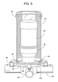
- a series of brackets 88 fasten a retaining ring 90 ( Figs. 3 and 5 ) to fan blade support arms 60 that extend from hub 52.
- Retaining ring 90 completely encircles side plate 22a and is disposed above lower plate 22c.
- An inner diameter of ring 90 is smaller than the outer diameter of lower plate 22c, so lower plate 22c cannot fit through the inner diameter of ring 90. Consequently, if hub 52 were to descend relative to drive shaft 22, the descent would stop when ring 90 or brackets 88 encounters lower plate 22c.
- ring 90 Upon engaging lower plate 22c, ring 90 being a continuous ring helps evenly distribute the weight of hub 52 and fan blades 12 among the series of ring-supporting brackets 88. In addition, ring 90 couples blade support arms 60 together, thus providing another redundant safety feature - should a support arm separate from the hub.
- fan 10 Additional notable features of fan 10 pertain to the fan's dynamic response during operation.
- the quantity, weight, and shape of fan blades 12 in conjunction with the fan blade's flexibility enhanced by resilient connector 20 causes the fan blade tips 14 to rise an appreciable amount in response to fan 10 forcing air downward.
- the rise of tips 14 is represented by the phantom lines of Figures 1 and 2 .
- the phantom lines show the elevation of fan blades 12 while rotating at the rated speed, and the solid lines represents fan blades 12 while stationary.
- each fan blade 12 preferably develops an individual airflow thrust 92 that creates an individual upward reaction force 94 that supports most of a single fan blade's weight.
- reaction force 94 supports substantially all of the blade's weight. This is possible with the current fan blade's tapered hollow geometry, which provides a fan blade that weighs between only one and three pounds per foot of its length.96.
- limiting the number of fan blades to six or less means that a cumulative airflow thrust 98 (total thrust exerted by fan 10) creates a cumulative reaction force 100 that is distributed over fewer blades, thereby increasing the upward flexing of each individual blade during operation.
- the cumulative reaction force 100 provided by the blades may be insufficient to place hanger 16 in compression, which might destabilize fan 10.
Landscapes
- Engineering & Computer Science (AREA)
- Mechanical Engineering (AREA)
- General Engineering & Computer Science (AREA)
- Chemical & Material Sciences (AREA)
- Combustion & Propulsion (AREA)
- Structures Of Non-Positive Displacement Pumps (AREA)
Claims (9)
- Deckenventilator, der an einer oben liegenden Struktur (48) befestigt werden kann, wobei der Deckenventilator (10) umfasst:eine Halterung (16), die an der oben liegenden Struktur (48) befestigt werden kann;einen Motor (24) mit einer Antriebswelle (32), die im Allgemeinen nach unten zeigt;eine Nabe (52), die mit der Antriebswelle (32) verbunden ist, sodass die Nabe (52) unter dem Motor (24) ist;mehrere Ventilatorblätter (12), die mit der Nabe (52) gekoppelt sind;mehrere Klammern (88), die mit der Nabe (52) gekoppelt sind;eine Klammeranordnung (22), die den Motor (24) mit der Halterung (16) koppelt;eine untere Platte (22c), die sich von der Klammeranordnung (22) erstreckt, sodass die untere Platte (22c) über der Nabe (52) ist; undeinen Rückhaltering (90), der mit den mehreren Klammern (88) verbunden ist und über der unteren Platte (22c) angeordnet ist, sodass die untere Platte (22c) und der Rückhaltering (90) eine relative vertikale Bewegung zwischen der Nabe (52) und der Klammeranordnung (22) beschränken, wenn die Nabe (52) bezüglich der Antriebswelle (32) des Motors (24) hinuntergehen sollte.
- Deckenventilator nach Anspruch 1, bei welchem der Rückhaltering (90) den Motor (90) umgibt.
- Deckenventilator nach Anspruch 1, bei welchem der Rückhaltering (90) die Antriebswelle (32) umgibt.
- Deckenventilator nach Anspruch 1, bei welchem die mehreren Klammern (88) und die mehreren Ventilatorblätter (12) in einer eins-zu-eins Zuordnung sind.
- Deckenventilator nach Anspruch 4, bei welchem die Nabe (52) mehrere Arme (60) umfasst, mit denen die mehreren Ventilatorblätter (12) verbunden sind, und die mehreren Klammern (88) an den mehreren Armen (60) angebracht sind.
- Deckenventilator nach Anspruch 5, bei welchem die mehreren Arme (60), die mehreren Klammern (88) und der Rückhaltering (90) im Wesentlichen im Bezug zueinander fest sind.
- Deckenventilator nach Anspruch 1, bei welchem die Klammeranordnung (22) eine redundante Kombination von Kehlnähten (38) und mechanischen Befestigungselementen (36) umfasst, die hilft, abzusichern, dass der Motor (24) mit der Halterung (16) gekoppelt bleibt.
- Deckenventilator nach Anspruch 1, bei welchem die Halterung (16) ein Paar Rohre (16a, 16b) umfasst, die in teleskopischem Eingriff stehen und einen im Wesentlichen rechtwinkligen Querschnitt aufweisen, wodurch das Paar Rohre (16a, 16b) die Halterung (16) aufgrund des Paars von Rohren (16a, 16b) vertikal einstellbar macht, die in teleskopischem Eingriff stehen, und die Halterung (16) einem Drehmoment aufgrund dem Paar Rohre (16a, 16b) widerstehen kann, die den im Allgemeinen rechtwinkligen Querschnitt aufweisen.
- Deckenventilator nach Anspruch 1, des Weiteren umfassend mehrere elastische Elemente (22), die helfen, die mehreren Ventilatorblätter (12) elastisch mit der Nabe (52) zu koppeln, sodass die mehreren Ventilatorblätter (12) sowohl nach oben als auch nach unten leichter auslenken können, als wenn die mehreren Ventilatorblätter (12) fester mit der Nabe (52) gekoppelt werden.
Applications Claiming Priority (2)
| Application Number | Priority Date | Filing Date | Title |
|---|---|---|---|
| US11/672,779 US7726945B2 (en) | 2007-02-08 | 2007-02-08 | Industrial ceiling fan |
| PCT/US2008/052019 WO2008097735A1 (en) | 2007-02-08 | 2008-01-25 | Industrial ceiling fan |
Publications (2)
| Publication Number | Publication Date |
|---|---|
| EP2126366A1 EP2126366A1 (de) | 2009-12-02 |
| EP2126366B1 true EP2126366B1 (de) | 2012-06-27 |
Family
ID=39448625
Family Applications (1)
| Application Number | Title | Priority Date | Filing Date |
|---|---|---|---|
| EP08728279A Active EP2126366B1 (de) | 2007-02-08 | 2008-01-25 | Deckenventilator für industriegebäude |
Country Status (7)
| Country | Link |
|---|---|
| US (1) | US7726945B2 (de) |
| EP (1) | EP2126366B1 (de) |
| CN (1) | CN101646873B (de) |
| CA (1) | CA2677645C (de) |
| ES (1) | ES2389962T3 (de) |
| MX (1) | MX2009008468A (de) |
| WO (1) | WO2008097735A1 (de) |
Families Citing this family (35)
| Publication number | Priority date | Publication date | Assignee | Title |
|---|---|---|---|---|
| US7955055B1 (en) * | 2006-04-14 | 2011-06-07 | Macroair Technologies, Inc. | Safety retaining system for large industrial fan |
| US8152453B2 (en) * | 2007-09-17 | 2012-04-10 | Delta T Corporation | Ceiling fan with angled mounting |
| US8622712B2 (en) * | 2008-08-11 | 2014-01-07 | Rite-Hite Holding Corporation | Sprinkler-compatible ceiling fans |
| US8579588B1 (en) | 2009-04-29 | 2013-11-12 | Macroair Technologies, Inc. | Hub assembly for a large cooling fan |
| USD631536S1 (en) | 2009-05-21 | 2011-01-25 | Rite-Hite Holding Corporation | Fan blade |
| CN101832285B (zh) * | 2010-04-29 | 2015-11-25 | 上海尔华杰机电装备制造有限公司 | 冷却用风机叶轮 |
| US9151514B2 (en) * | 2011-05-09 | 2015-10-06 | Canopy Breezes, Llc | Universal canopy suspension system |
| ITMI20120042A1 (it) * | 2012-01-17 | 2013-07-18 | Cmp Impianti S R L | Dispositivo per la ventilazione di un ambiente |
| CN102536864B (zh) * | 2012-03-20 | 2015-11-18 | 开勒环境科技(上海)股份有限公司 | 一种大型吊式工业风扇 |
| US9011099B2 (en) | 2012-06-19 | 2015-04-21 | Skyblade Fan Company | High volume low speed fan |
| US8842000B2 (en) | 2012-07-17 | 2014-09-23 | 4Front Engineered Solutions, Inc. | Fire control systems |
| CN103410790A (zh) * | 2013-08-19 | 2013-11-27 | 中山市奥美森工业有限公司 | 一种工业用吊扇 |
| USD716437S1 (en) | 2014-01-17 | 2014-10-28 | Patterson Ventilation Company, Inc. | Ceiling fan hub and blade assembly |
| US9874214B2 (en) | 2014-01-28 | 2018-01-23 | 4Front Engineered Solutions, Inc. | Fan with fan blade mounting structure |
| WO2015181774A1 (en) * | 2014-05-30 | 2015-12-03 | Almishari Ibrahim | System and method of a fan |
| WO2016075575A1 (en) * | 2014-11-11 | 2016-05-19 | Cofimco S.R.L. | Blade unit for industrial fans |
| GB2538938B (en) * | 2015-03-26 | 2017-07-26 | Asg Group Ltd | Mounting arrangement |
| US9726192B2 (en) | 2015-03-31 | 2017-08-08 | Assa Abloy Entrance Systems Ab | Fan blades and associated blade tips |
| US9897095B2 (en) | 2015-05-01 | 2018-02-20 | Hunter Fan Company | Ceiling fan kit and method of mounting |
| US11674526B2 (en) | 2016-01-22 | 2023-06-13 | Hunter Fan Company | Ceiling fan having a dual redundant motor mounting assembly |
| EP4407188A3 (de) | 2015-12-14 | 2024-10-23 | Hunter Fan Company | Deckenventilator |
| CN108488081B (zh) * | 2016-03-29 | 2019-09-17 | 浙江富地机械有限公司 | 一种大型吊扇 |
| IT201700009043A1 (it) * | 2017-01-27 | 2018-07-27 | Arienti & C S R L | Dispositivo di ventilazione |
| US11846299B2 (en) | 2018-01-02 | 2023-12-19 | Phansee Company, LLC | Fan |
| US10935034B2 (en) | 2018-01-02 | 2021-03-02 | Phansee Company, LLC | Fan |
| US10844866B2 (en) | 2018-06-15 | 2020-11-24 | Euclid Design Group, Llc | Box fan apparatus with multi-adaptive suspension |
| US11486412B1 (en) * | 2019-03-08 | 2022-11-01 | Delta T, Llc | Fan blade retention system and related methods |
| CN110056520B (zh) * | 2019-03-13 | 2021-02-05 | 咸阳职业技术学院 | 一种基于电子技术的双向自动清理换气装置 |
| CN110736159B (zh) * | 2019-09-24 | 2021-09-21 | 青岛海尔空调器有限总公司 | 空调外机及空调 |
| KR102356659B1 (ko) * | 2020-09-29 | 2022-02-07 | (주) 동광라이팅 | 유선형 곡선 블레이드를 이용한 공기순환장치 |
| USD1010802S1 (en) * | 2021-02-09 | 2024-01-09 | Hunter Fan Company | Telescopic down rod assembly |
| IT202100023681A1 (it) * | 2021-09-14 | 2023-03-14 | Gigola & Riccardi S P A | Dispositivo di ventilazione di un ambiente |
| TWM633905U (zh) * | 2021-09-24 | 2022-11-11 | 閎博科技有限公司 | 吊扇及其吊扇環繞裝置 |
| USD1001265S1 (en) * | 2022-03-29 | 2023-10-10 | Hunter Fan Company | Telescopic down rod assembly |
| US12085091B2 (en) * | 2022-07-07 | 2024-09-10 | Hunter Fan Company | Ceiling fan hanger assembly |
Family Cites Families (59)
| Publication number | Priority date | Publication date | Assignee | Title |
|---|---|---|---|---|
| US511519A (en) * | 1893-12-26 | Ventilating-fan for mines | ||
| US399973A (en) * | 1889-03-19 | Rotary fan for fruit-driers | ||
| US578360A (en) * | 1897-03-09 | James j | ||
| US2736137A (en) * | 1956-02-28 | thaheld | ||
| US681710A (en) * | 1899-08-26 | 1901-09-03 | Automatic Speed Governor Company Ltd | Speed-governor for fans. |
| US921744A (en) * | 1908-05-12 | 1909-05-18 | William D Scott | Ventilating-fan for mines. |
| US1501201A (en) * | 1922-12-08 | 1924-07-15 | Laurence A Cates | Ventilating fan |
| US1642205A (en) * | 1927-01-15 | 1927-09-13 | Hosch J Claude | Fan |
| US3051072A (en) * | 1961-03-20 | 1962-08-28 | Hoy R Bohanon | Air circulating and mixing fan |
| US3689971A (en) * | 1967-08-31 | 1972-09-12 | Eugene M Davidson | Axial flow fans |
| US3768546A (en) * | 1971-12-27 | 1973-10-30 | Hudson Products Corp | Axial flow fan assembly |
| US3818813A (en) * | 1973-01-05 | 1974-06-25 | Julian Eng | Atmosphere circulation system |
| US4008007A (en) * | 1975-05-23 | 1977-02-15 | Hudson Products Corporation | Axial flow fan assembly |
| FR2391428A1 (fr) * | 1977-05-18 | 1978-12-15 | Delta Neu Sa | Unite de ventilation et de conditionnement de zone par evaporation adiabatique sous toiture |
| US4202655A (en) * | 1977-06-10 | 1980-05-13 | Maloof Ralph P | Propeller fan blading and hub therefor |
| US4373241A (en) * | 1977-06-10 | 1983-02-15 | Maloof Ralph P | Method of making propeller blade |
| US4275993A (en) * | 1978-07-14 | 1981-06-30 | Stanley Industrial Corporation | Composite fan blade assembly |
| US4263842A (en) * | 1978-08-02 | 1981-04-28 | Moore Robert D | Adjustable louver assembly |
| US4640668A (en) * | 1982-08-02 | 1987-02-03 | Yang Tai Her | Ceiling fan with adjustable blowing scope thru a speed-servo and with driving speed control means |
| US4522255A (en) * | 1982-08-05 | 1985-06-11 | Baker Gary C | Spot thermal or environmental conditioner |
| US4473000A (en) * | 1982-11-26 | 1984-09-25 | Vertical Air Stabilization Corp. | Air blower with air directing vanes |
| US4730551A (en) * | 1986-11-03 | 1988-03-15 | Peludat Walter W | Heat distributor for suspended ceilings |
| US4779671A (en) * | 1987-06-05 | 1988-10-25 | Dewey Dolison | Cooling, heating and ventilation system |
| CN2030665U (zh) * | 1987-07-16 | 1989-01-11 | 甘镇中 | 立体风吊扇 |
| US4822246A (en) * | 1988-07-19 | 1989-04-18 | Hsu Yun Tung | Fan for moving fluid axially and radially |
| US4892460A (en) * | 1989-01-30 | 1990-01-09 | Volk Steve J | Propeller breeze enhancing blades for conventional ceiling fans |
| US4973016A (en) * | 1989-07-24 | 1990-11-27 | Patton Electric Company, Inc. | Dock fan and light cantilever-mounted articulated multi-arm utility support assembly |
| US5096384A (en) * | 1990-07-27 | 1992-03-17 | The Marley Cooling Tower Company | Plastic fan blade for industrial cooling towers and method of making same |
| US5078574A (en) * | 1990-11-19 | 1992-01-07 | Olsen George D | Device for minimizing room temperature gradients |
| US5615855A (en) | 1991-10-07 | 1997-04-01 | Tri-Ex Tower Corporation | Telescoping mast with integral payload |
| US5246343A (en) * | 1991-12-23 | 1993-09-21 | Emerson Electric Co. | Fan assemblies and method of making same |
| US5328329A (en) * | 1993-07-06 | 1994-07-12 | Hudson Products Corporation | Fan blade width extender |
| US5567200A (en) * | 1993-12-01 | 1996-10-22 | Ctb Inc. | Method and apparatus for circulating air |
| US5542819A (en) * | 1995-02-14 | 1996-08-06 | Chien Luen Industries Company, Ltd., Inc. | Ceiling fan safety tether |
| US6039533A (en) * | 1995-07-31 | 2000-03-21 | Mccabe; Francis J. | Fan blade, structures and methods |
| US6030179A (en) * | 1995-07-31 | 2000-02-29 | Mccabe; Francis J. | Airfoil structures and method |
| US5860788A (en) * | 1996-06-14 | 1999-01-19 | Shell Electric Mfg. (Holdings) Co. Ltd. | Low drag fan assembly |
| US5709458A (en) * | 1996-08-14 | 1998-01-20 | Metz; Donald | Dock light |
| US5795220A (en) * | 1997-03-20 | 1998-08-18 | Core; William Roger | Ceiling fan with an air diffuser system |
| US6039541A (en) * | 1998-04-07 | 2000-03-21 | University Of Central Florida | High efficiency ceiling fan |
| US6022191A (en) | 1998-05-15 | 2000-02-08 | The Moore Company | Fan blade mounting |
| US6244821B1 (en) | 1999-02-19 | 2001-06-12 | Mechanization Systems Company, Inc. | Low speed cooling fan |
| US6386828B1 (en) * | 2000-01-03 | 2002-05-14 | Aerotech, Inc. | Ventilation fan |
| US20020045420A1 (en) * | 2000-10-13 | 2002-04-18 | Daniel Taillon | Loading dock vehicle ventilation system |
| US6812849B1 (en) * | 2000-12-12 | 2004-11-02 | Thomas A. Ancel | Loading dock traffic automation |
| US6443702B1 (en) * | 2000-12-29 | 2002-09-03 | Curtis O. Ross | Motorized ceiling fan lifting and lowering apparatus |
| US6644928B1 (en) * | 2002-04-29 | 2003-11-11 | David Tang | Retractable suspension device of a ceiling fan |
| US6890149B2 (en) * | 2002-06-05 | 2005-05-10 | Donald Metz | Laminar flow air mover |
| US6692229B2 (en) * | 2002-06-05 | 2004-02-17 | Donald Metz | Laminar flow air mover |
| US6719533B2 (en) * | 2002-07-11 | 2004-04-13 | Hunter Fan Company | High efficiency ceiling fan |
| US6733241B2 (en) * | 2002-07-11 | 2004-05-11 | Hunter Fan Company | High efficiency ceiling fan |
| US6719532B2 (en) * | 2002-07-11 | 2004-04-13 | Hunter Fan Company | High efficiency ceiling fan |
| CN100374731C (zh) * | 2002-07-30 | 2008-03-12 | 亨特风扇公司 | 吊扇 |
| US6939108B2 (en) | 2003-01-06 | 2005-09-06 | Mechanization Systems Company, Inc. | Cooling fan with reinforced blade |
| US7066721B2 (en) | 2003-06-11 | 2006-06-27 | Hunter Fan Company | Ceiling fan motors |
| US7381129B2 (en) * | 2004-03-15 | 2008-06-03 | Airius, Llc. | Columnar air moving devices, systems and methods |
| USD514688S1 (en) * | 2004-08-30 | 2006-02-07 | Airius, Llc | Air moving device |
| US20070134093A1 (en) * | 2005-12-13 | 2007-06-14 | Thomas Weiler | Device and method for raising and lowering ceiling fixtures |
| DE202005019872U1 (de) | 2005-12-20 | 2006-07-27 | Canova, Vincenzo | Ventilatorgehäuse |
-
2007
- 2007-02-08 US US11/672,779 patent/US7726945B2/en active Active
-
2008
- 2008-01-25 CA CA2677645A patent/CA2677645C/en active Active
- 2008-01-25 WO PCT/US2008/052019 patent/WO2008097735A1/en not_active Ceased
- 2008-01-25 CN CN2008800043476A patent/CN101646873B/zh active Active
- 2008-01-25 MX MX2009008468A patent/MX2009008468A/es active IP Right Grant
- 2008-01-25 EP EP08728279A patent/EP2126366B1/de active Active
- 2008-01-25 ES ES08728279T patent/ES2389962T3/es active Active
Also Published As
| Publication number | Publication date |
|---|---|
| US20080193294A1 (en) | 2008-08-14 |
| WO2008097735A1 (en) | 2008-08-14 |
| MX2009008468A (es) | 2009-10-14 |
| US7726945B2 (en) | 2010-06-01 |
| EP2126366A1 (de) | 2009-12-02 |
| CA2677645A1 (en) | 2008-08-14 |
| CA2677645C (en) | 2012-03-13 |
| ES2389962T3 (es) | 2012-11-05 |
| CN101646873A (zh) | 2010-02-10 |
| CN101646873B (zh) | 2011-06-08 |
Similar Documents
| Publication | Publication Date | Title |
|---|---|---|
| EP2126366B1 (de) | Deckenventilator für industriegebäude | |
| CN101842036B (zh) | 具有角度安装件的吊扇 | |
| US6458028B2 (en) | Diffuser and ceiling fan combination | |
| US8336844B2 (en) | Mounting system for supporting a ceiling fan assembly | |
| CN108700082B (zh) | 吊扇 | |
| US6382917B1 (en) | Ceiling fan having side mounted blade irons | |
| CN101821934B (zh) | 具有同心静止管和掉电特征的吊扇 | |
| US20060255226A1 (en) | Ball and socket assembly for suspending an object from a sloped surface | |
| US20190383295A1 (en) | Box fan apparatus with multi-adaptive suspension | |
| CA2862353A1 (en) | Fan with resilient hub | |
| AU2008200444A1 (en) | Mounting system for supporting a ceiling fan assembly | |
| US20080175713A1 (en) | Fan blade mounting system | |
| US20200063759A1 (en) | Ceiling fan hanger assembly | |
| KR101963541B1 (ko) | 각도조절이 가능한 축사용 환풍기 | |
| WO2020204979A1 (en) | Fan blade mounting structures and arrangements | |
| KR200436206Y1 (ko) | 천정형 송풍기 풍향조절장치 | |
| JP7445690B2 (ja) | シーリングファン | |
| CN216554535U (zh) | 多级防掉落工业吊扇 | |
| EP4660548A1 (de) | Montageelement zur befestigung eines mechanischen lüfters in einer dachentlüftungsvorrichtung und dachentlüftungsvorrichtung | |
| CN223424270U (zh) | 一种工业大吊扇连接结构 | |
| CA2299810A1 (en) | Ceiling fan having side mounted blade irons | |
| WO2025250458A1 (en) | Blade retention system for fan and related methods |
Legal Events
| Date | Code | Title | Description |
|---|---|---|---|
| PUAI | Public reference made under article 153(3) epc to a published international application that has entered the european phase |
Free format text: ORIGINAL CODE: 0009012 |
|
| 17P | Request for examination filed |
Effective date: 20090806 |
|
| AK | Designated contracting states |
Kind code of ref document: A1 Designated state(s): AT BE BG CH CY CZ DE DK EE ES FI FR GB GR HR HU IE IS IT LI LT LU LV MC MT NL NO PL PT RO SE SI SK TR |
|
| DAX | Request for extension of the european patent (deleted) | ||
| 17Q | First examination report despatched |
Effective date: 20100531 |
|
| GRAP | Despatch of communication of intention to grant a patent |
Free format text: ORIGINAL CODE: EPIDOSNIGR1 |
|
| RIC1 | Information provided on ipc code assigned before grant |
Ipc: F04D 25/08 20060101AFI20120105BHEP Ipc: F04D 29/64 20060101ALI20120105BHEP Ipc: F04D 29/32 20060101ALI20120105BHEP Ipc: F04D 29/34 20060101ALI20120105BHEP Ipc: F24F 7/007 20060101ALI20120105BHEP Ipc: F04D 29/60 20060101ALI20120105BHEP |
|
| GRAS | Grant fee paid |
Free format text: ORIGINAL CODE: EPIDOSNIGR3 |
|
| GRAA | (expected) grant |
Free format text: ORIGINAL CODE: 0009210 |
|
| AK | Designated contracting states |
Kind code of ref document: B1 Designated state(s): AT BE BG CH CY CZ DE DK EE ES FI FR GB GR HR HU IE IS IT LI LT LU LV MC MT NL NO PL PT RO SE SI SK TR |
|
| REG | Reference to a national code |
Ref country code: GB Ref legal event code: FG4D |
|
| REG | Reference to a national code |
Ref country code: CH Ref legal event code: EP |
|
| REG | Reference to a national code |
Ref country code: AT Ref legal event code: REF Ref document number: 564400 Country of ref document: AT Kind code of ref document: T Effective date: 20120715 |
|
| REG | Reference to a national code |
Ref country code: IE Ref legal event code: FG4D |
|
| REG | Reference to a national code |
Ref country code: DE Ref legal event code: R096 Ref document number: 602008016765 Country of ref document: DE Effective date: 20120830 |
|
| REG | Reference to a national code |
Ref country code: NL Ref legal event code: T3 |
|
| PG25 | Lapsed in a contracting state [announced via postgrant information from national office to epo] |
Ref country code: FI Free format text: LAPSE BECAUSE OF FAILURE TO SUBMIT A TRANSLATION OF THE DESCRIPTION OR TO PAY THE FEE WITHIN THE PRESCRIBED TIME-LIMIT Effective date: 20120627 Ref country code: LT Free format text: LAPSE BECAUSE OF FAILURE TO SUBMIT A TRANSLATION OF THE DESCRIPTION OR TO PAY THE FEE WITHIN THE PRESCRIBED TIME-LIMIT Effective date: 20120627 Ref country code: SE Free format text: LAPSE BECAUSE OF FAILURE TO SUBMIT A TRANSLATION OF THE DESCRIPTION OR TO PAY THE FEE WITHIN THE PRESCRIBED TIME-LIMIT Effective date: 20120627 Ref country code: NO Free format text: LAPSE BECAUSE OF FAILURE TO SUBMIT A TRANSLATION OF THE DESCRIPTION OR TO PAY THE FEE WITHIN THE PRESCRIBED TIME-LIMIT Effective date: 20120927 |
|
| REG | Reference to a national code |
Ref country code: ES Ref legal event code: FG2A Ref document number: 2389962 Country of ref document: ES Kind code of ref document: T3 Effective date: 20121105 |
|
| REG | Reference to a national code |
Ref country code: AT Ref legal event code: MK05 Ref document number: 564400 Country of ref document: AT Kind code of ref document: T Effective date: 20120627 |
|
| REG | Reference to a national code |
Ref country code: LT Ref legal event code: MG4D Effective date: 20120627 |
|
| PG25 | Lapsed in a contracting state [announced via postgrant information from national office to epo] |
Ref country code: SI Free format text: LAPSE BECAUSE OF FAILURE TO SUBMIT A TRANSLATION OF THE DESCRIPTION OR TO PAY THE FEE WITHIN THE PRESCRIBED TIME-LIMIT Effective date: 20120627 Ref country code: LV Free format text: LAPSE BECAUSE OF FAILURE TO SUBMIT A TRANSLATION OF THE DESCRIPTION OR TO PAY THE FEE WITHIN THE PRESCRIBED TIME-LIMIT Effective date: 20120627 Ref country code: GR Free format text: LAPSE BECAUSE OF FAILURE TO SUBMIT A TRANSLATION OF THE DESCRIPTION OR TO PAY THE FEE WITHIN THE PRESCRIBED TIME-LIMIT Effective date: 20120928 Ref country code: HR Free format text: LAPSE BECAUSE OF FAILURE TO SUBMIT A TRANSLATION OF THE DESCRIPTION OR TO PAY THE FEE WITHIN THE PRESCRIBED TIME-LIMIT Effective date: 20120627 |
|
| PG25 | Lapsed in a contracting state [announced via postgrant information from national office to epo] |
Ref country code: RO Free format text: LAPSE BECAUSE OF FAILURE TO SUBMIT A TRANSLATION OF THE DESCRIPTION OR TO PAY THE FEE WITHIN THE PRESCRIBED TIME-LIMIT Effective date: 20120627 Ref country code: AT Free format text: LAPSE BECAUSE OF FAILURE TO SUBMIT A TRANSLATION OF THE DESCRIPTION OR TO PAY THE FEE WITHIN THE PRESCRIBED TIME-LIMIT Effective date: 20120627 Ref country code: CZ Free format text: LAPSE BECAUSE OF FAILURE TO SUBMIT A TRANSLATION OF THE DESCRIPTION OR TO PAY THE FEE WITHIN THE PRESCRIBED TIME-LIMIT Effective date: 20120627 Ref country code: CY Free format text: LAPSE BECAUSE OF FAILURE TO SUBMIT A TRANSLATION OF THE DESCRIPTION OR TO PAY THE FEE WITHIN THE PRESCRIBED TIME-LIMIT Effective date: 20120627 Ref country code: EE Free format text: LAPSE BECAUSE OF FAILURE TO SUBMIT A TRANSLATION OF THE DESCRIPTION OR TO PAY THE FEE WITHIN THE PRESCRIBED TIME-LIMIT Effective date: 20120627 Ref country code: SK Free format text: LAPSE BECAUSE OF FAILURE TO SUBMIT A TRANSLATION OF THE DESCRIPTION OR TO PAY THE FEE WITHIN THE PRESCRIBED TIME-LIMIT Effective date: 20120627 Ref country code: BE Free format text: LAPSE BECAUSE OF FAILURE TO SUBMIT A TRANSLATION OF THE DESCRIPTION OR TO PAY THE FEE WITHIN THE PRESCRIBED TIME-LIMIT Effective date: 20120627 Ref country code: IS Free format text: LAPSE BECAUSE OF FAILURE TO SUBMIT A TRANSLATION OF THE DESCRIPTION OR TO PAY THE FEE WITHIN THE PRESCRIBED TIME-LIMIT Effective date: 20121027 |
|
| PG25 | Lapsed in a contracting state [announced via postgrant information from national office to epo] |
Ref country code: PL Free format text: LAPSE BECAUSE OF FAILURE TO SUBMIT A TRANSLATION OF THE DESCRIPTION OR TO PAY THE FEE WITHIN THE PRESCRIBED TIME-LIMIT Effective date: 20120627 Ref country code: PT Free format text: LAPSE BECAUSE OF FAILURE TO SUBMIT A TRANSLATION OF THE DESCRIPTION OR TO PAY THE FEE WITHIN THE PRESCRIBED TIME-LIMIT Effective date: 20121029 |
|
| PG25 | Lapsed in a contracting state [announced via postgrant information from national office to epo] |
Ref country code: DK Free format text: LAPSE BECAUSE OF FAILURE TO SUBMIT A TRANSLATION OF THE DESCRIPTION OR TO PAY THE FEE WITHIN THE PRESCRIBED TIME-LIMIT Effective date: 20120627 |
|
| PLBE | No opposition filed within time limit |
Free format text: ORIGINAL CODE: 0009261 |
|
| STAA | Information on the status of an ep patent application or granted ep patent |
Free format text: STATUS: NO OPPOSITION FILED WITHIN TIME LIMIT |
|
| 26N | No opposition filed |
Effective date: 20130328 |
|
| REG | Reference to a national code |
Ref country code: DE Ref legal event code: R097 Ref document number: 602008016765 Country of ref document: DE Effective date: 20130328 |
|
| PG25 | Lapsed in a contracting state [announced via postgrant information from national office to epo] |
Ref country code: BG Free format text: LAPSE BECAUSE OF FAILURE TO SUBMIT A TRANSLATION OF THE DESCRIPTION OR TO PAY THE FEE WITHIN THE PRESCRIBED TIME-LIMIT Effective date: 20120927 |
|
| PG25 | Lapsed in a contracting state [announced via postgrant information from national office to epo] |
Ref country code: MC Free format text: LAPSE BECAUSE OF NON-PAYMENT OF DUE FEES Effective date: 20130131 |
|
| REG | Reference to a national code |
Ref country code: CH Ref legal event code: PL |
|
| REG | Reference to a national code |
Ref country code: IE Ref legal event code: MM4A |
|
| PG25 | Lapsed in a contracting state [announced via postgrant information from national office to epo] |
Ref country code: LI Free format text: LAPSE BECAUSE OF NON-PAYMENT OF DUE FEES Effective date: 20130131 Ref country code: CH Free format text: LAPSE BECAUSE OF NON-PAYMENT OF DUE FEES Effective date: 20130131 |
|
| PG25 | Lapsed in a contracting state [announced via postgrant information from national office to epo] |
Ref country code: IE Free format text: LAPSE BECAUSE OF NON-PAYMENT OF DUE FEES Effective date: 20130125 |
|
| PG25 | Lapsed in a contracting state [announced via postgrant information from national office to epo] |
Ref country code: MT Free format text: LAPSE BECAUSE OF FAILURE TO SUBMIT A TRANSLATION OF THE DESCRIPTION OR TO PAY THE FEE WITHIN THE PRESCRIBED TIME-LIMIT Effective date: 20120627 |
|
| PG25 | Lapsed in a contracting state [announced via postgrant information from national office to epo] |
Ref country code: TR Free format text: LAPSE BECAUSE OF FAILURE TO SUBMIT A TRANSLATION OF THE DESCRIPTION OR TO PAY THE FEE WITHIN THE PRESCRIBED TIME-LIMIT Effective date: 20120627 |
|
| PG25 | Lapsed in a contracting state [announced via postgrant information from national office to epo] |
Ref country code: LU Free format text: LAPSE BECAUSE OF NON-PAYMENT OF DUE FEES Effective date: 20130125 Ref country code: HU Free format text: LAPSE BECAUSE OF FAILURE TO SUBMIT A TRANSLATION OF THE DESCRIPTION OR TO PAY THE FEE WITHIN THE PRESCRIBED TIME-LIMIT; INVALID AB INITIO Effective date: 20080125 |
|
| REG | Reference to a national code |
Ref country code: FR Ref legal event code: PLFP Year of fee payment: 9 |
|
| REG | Reference to a national code |
Ref country code: FR Ref legal event code: PLFP Year of fee payment: 10 |
|
| REG | Reference to a national code |
Ref country code: FR Ref legal event code: PLFP Year of fee payment: 11 |
|
| PGFP | Annual fee paid to national office [announced via postgrant information from national office to epo] |
Ref country code: DE Payment date: 20241203 Year of fee payment: 18 |
|
| PGFP | Annual fee paid to national office [announced via postgrant information from national office to epo] |
Ref country code: ES Payment date: 20250206 Year of fee payment: 18 |
|
| PGFP | Annual fee paid to national office [announced via postgrant information from national office to epo] |
Ref country code: IT Payment date: 20241210 Year of fee payment: 18 |
|
| PGFP | Annual fee paid to national office [announced via postgrant information from national office to epo] |
Ref country code: GB Payment date: 20251204 Year of fee payment: 19 |
|
| PGFP | Annual fee paid to national office [announced via postgrant information from national office to epo] |
Ref country code: NL Payment date: 20251215 Year of fee payment: 19 Ref country code: FR Payment date: 20251208 Year of fee payment: 19 |