EP2124365A2 - Digital processing of SONET pointers - Google Patents
Digital processing of SONET pointers Download PDFInfo
- Publication number
- EP2124365A2 EP2124365A2 EP09168627A EP09168627A EP2124365A2 EP 2124365 A2 EP2124365 A2 EP 2124365A2 EP 09168627 A EP09168627 A EP 09168627A EP 09168627 A EP09168627 A EP 09168627A EP 2124365 A2 EP2124365 A2 EP 2124365A2
- Authority
- EP
- European Patent Office
- Prior art keywords
- pointer
- reference frequency
- local reference
- dpll
- signal
- Prior art date
- Legal status (The legal status is an assumption and is not a legal conclusion. Google has not performed a legal analysis and makes no representation as to the accuracy of the status listed.)
- Withdrawn
Links
- RGNPBRKPHBKNKX-UHFFFAOYSA-N hexaflumuron Chemical compound C1=C(Cl)C(OC(F)(F)C(F)F)=C(Cl)C=C1NC(=O)NC(=O)C1=C(F)C=CC=C1F RGNPBRKPHBKNKX-UHFFFAOYSA-N 0.000 title claims abstract 3
- 238000012545 processing Methods 0.000 title claims description 14
- 238000000034 method Methods 0.000 claims abstract description 42
- 230000008859 change Effects 0.000 claims description 24
- 238000001914 filtration Methods 0.000 claims description 10
- 230000006870 function Effects 0.000 description 14
- 230000001360 synchronised effect Effects 0.000 description 14
- 238000010586 diagram Methods 0.000 description 7
- 230000003287 optical effect Effects 0.000 description 6
- 230000008901 benefit Effects 0.000 description 4
- 238000004891 communication Methods 0.000 description 4
- 239000000284 extract Substances 0.000 description 3
- 238000003780 insertion Methods 0.000 description 3
- 230000037431 insertion Effects 0.000 description 3
- 238000013507 mapping Methods 0.000 description 3
- 239000000203 mixture Substances 0.000 description 3
- 238000012544 monitoring process Methods 0.000 description 3
- 230000007704 transition Effects 0.000 description 3
- 230000005540 biological transmission Effects 0.000 description 2
- 230000003139 buffering effect Effects 0.000 description 2
- 230000000694 effects Effects 0.000 description 2
- 238000009472 formulation Methods 0.000 description 2
- 238000005259 measurement Methods 0.000 description 2
- 238000000059 patterning Methods 0.000 description 2
- 230000008569 process Effects 0.000 description 2
- 238000011084 recovery Methods 0.000 description 2
- 230000009467 reduction Effects 0.000 description 2
- 230000004044 response Effects 0.000 description 2
- 238000000926 separation method Methods 0.000 description 2
- 238000012546 transfer Methods 0.000 description 2
- 230000018199 S phase Effects 0.000 description 1
- 238000004458 analytical method Methods 0.000 description 1
- 238000013459 approach Methods 0.000 description 1
- 238000010420 art technique Methods 0.000 description 1
- 230000015556 catabolic process Effects 0.000 description 1
- 238000006731 degradation reaction Methods 0.000 description 1
- 230000009977 dual effect Effects 0.000 description 1
- 230000007246 mechanism Effects 0.000 description 1
- 238000005457 optimization Methods 0.000 description 1
- 230000000737 periodic effect Effects 0.000 description 1
- 238000003672 processing method Methods 0.000 description 1
Images


Classifications
-
- H—ELECTRICITY
- H04—ELECTRIC COMMUNICATION TECHNIQUE
- H04J—MULTIPLEX COMMUNICATION
- H04J3/00—Time-division multiplex systems
- H04J3/02—Details
- H04J3/06—Synchronising arrangements
- H04J3/07—Synchronising arrangements using pulse stuffing for systems with different or fluctuating information rates or bit rates
- H04J3/076—Bit and byte stuffing, e.g. SDH/PDH desynchronisers, bit-leaking
Definitions
- This invention relates to communications networks, and in particular to a method for digitally processing SONET pointers.
- SONET Synchronous Optical Network
- SDH Synchronous Digital Hierarchy
- SONET/SDH A significant amount of SONET/SDH infrastructure has been installed, particularly within the network core.
- This SONET infrastructure is used to transport asynchronous subscriber signal traffic having differing formats, such as Asynchronous Transfer Mode (ATM), Internet Protocol (IP), etc.
- ATM Asynchronous Transfer Mode
- IP Internet Protocol
- STS/STM Synchronous Transfer Signal
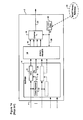
- FIG. 1a is a block diagram schematically illustrating principal operations of a conventional transmitting node 2 of an optical communications system.
- asynchronous subscriber traffic within multiple tributaries 4 is received by the node 2 and buffered in an elastic store 6.
- the traffic may comprise any arbitrary mix of signals, including DS-1, DS-3 and E1 traffic.
- Traffic within each tributary 4 is normally buffered in a respective First-In-First-Out (FIFO) buffer 8.
- FIFO First-In-First-Out
- the timing of this buffering operation is controlled by a data clock signal 10 having a frequency f1 generated by a tributary clock recovery circuit 12.
- a synchronizing framer 14 reads data from each FIFO 8, and maps the read data into corresponding tributaries of a number of SONET Synchronous Payload Envelopes (SPEs) 16, using a known format such as those defined in the SONET standard. Each SPE 16 is then passed to a channel transmitter (Tx) 18, which inserts the SPEs into an STS frame, and then modulates the STS frame onto an optical channel carrier 20 for transmission through the optical network.
- Tx local clock 22 which is synchronous with a SONET Primary Reference 24, generates a respective TX local clock signal 26 having a frequency f2, which is used to control operation of the synchronizing framer 14 and channel Tx 18.
- the number and size of the SPEs 16 are selected based on the channel line rate. For example, for a channel line rate of 10Gb/s, the synchronizing framer 14 may map subscriber traffic into a set of four STS-48 envelopes. Other combinations may equally be used, such as, for example, eight STS-12 envelopes.
- a respective buffer fill signal 28 is generated for each tributary FIFO 8, and used to control the insertion of stuffing bits into the corresponding SPE tributary.
- the incoming STS 20 is decoded by a channel receiver (Rx) 32 and processed by a pointer processor 34 to demap each SPE tributary from the STS 20.
- Rx channel receiver
- PLL Phase locked Loop
- a buffer fill signal 44 generated by the tributary FIFO 36 is used to steer the Phase locked Loop (PLL) 42, so that the PLL output constitutes a recovered data clock signal 46 having a frequency f4 which approximates the data rate of the subscriber traffic.
- PLL Phase locked Loop
- a desynchronizer framer 48 can generate a recovered subscriber signal 50 in which the original timing is closely approximated.
- the introduction of idle packets to replace "missing" subscriber traffic enables the synchronizing and desynchronizing framers 14 and 48 to compensate any differences between the tributary data rate and the channel rate.
- this mapping technique suffers a limitation in that the fill signal 44 of the Rx tributary FIFO buffer 3b tends to vary in a step-wise manner as idle packets are inserted and striped from SPE tributaries. This causes timing jitter in the recovered subscriber signal 50.
- timing jitter introduced by mapping and demapping asynchronous client signal traffic to and from STS frames does not create any difficulties.
- the timing of the subscriber signal is critical, such as an HDTV signal or a subscriber-originated SONET signal (e.g. for SONET over SONET applications) the introduced timing jitter can noticeably degrade the quality of the subscriber's signal. Accordingly, there is interest in methods that enable subscriber traffic to be transparently mapped on to SONET STS signals. An important aspect for transparency is to preserve the original timing information of the subscriber signal.
- a multi-bit digital timing estimate is calculated (at 52) to indicate the difference between the tributary data rate f1, and the Tx local clock frequency f2.
- the timing estimate F is computed as a ratio between f1 and f2.
- the timing estimate F may be computed as a phase difference between the subscriber data signal and Tx local clock signal, calculated at the time that a corresponding client data block is mapped into the SPE.
- the timing estimate F is supplied to the synchronizing framer 14 and used in place of the tributary fill 28 to control the insertion of stuff bytes into the SPE tributary.
- the timing estimate F is also inserted into the SPE tributary and conveyed with the subscriber data to the terminating node 30.
- the pointer processor 34 demaps each SPE tributary, and extracts the timing estimate F.
- the timing estimate F extracted from the SPE tributary is used in place of the elastic store fill signal 44 to steer the desynchronizer Phase locked Loop (PLL) 54. Consequently, the PLL output constitutes a recovered data clock signal 56 having a frequency f4 which more closely approximates the original frequency f1 of the subscriber traffic.
- the desynchronizer framer 48 can generate a recovered subscriber signal 50 in which the original timing is substantially restored.
- Timing estimate F enables the transparent transport of the subscriber's original phase variations over a reasonable bandwidth (e.g. 100 Hz - 1 KHz).
- a reasonable bandwidth e.g. 100 Hz - 1 KHz.
- waiting time jitter is reduced by narrowing the bandwidth of the desynchronizer PLL 42 (see FIG. 1b ).
- very narrow filtering at the desynchronizer PLL 42 has the effect of attenuating the subscriber signal's phase variations and hence looses some transparency of the subscriber timing characteristics.
- United States Patent Application No. 09/972,686 overcomes this limitation by the accurate measurement of subscriber phase/frequency at the synchronizer 2. This information is encoded within the STS frame (in the form of timing estimate F) and used to steer the desynchronizer PLL 54, which substantially eliminates waiting time jitter.
- United States Patent Application No. 09/972,686 Another important attribute of United States Patent Application No. 09/972,686 is that, unlike conventional systems, an elastic store fill signals 28 and 44 are not used to control insertion of stuff bytes at either the transmitting or receiving nodes 2, 30. This avoids problems due to the fill signals 22 and 44 containing clock noise, cross-talk from other signals, and data patterning. Instead of the elastic store fill signals 22 and 44, United States Patent Application No. 09/972,686 uses the timing estimate F as an accurate measurement of the subscriber phase/frequency to drive stuffing at the transmitting node 2 and generation of the recovered data clock signal 56 at the receiving node 30.
- a limitation of United States Patent Application No. 09/972,686 is that subscriber signal phase and frequency information (F) is measured with respect to the Tx local clock signal 26 ( FIG. 2a ) at the originating node 2, whereas the recovered data clock signal 56 generated by the desynchronizer PLL 54 is based on the Rx local clock signal 40 at the terminating node 30.
- both of the Tx and Rx clock signals 26 and 40 are derived from the same SONET primary reference 24, and thus will be synchronous.
- the originating and terminating nodes 2 and 30 may well be situated in different SONET islands, with the result that there may be a frequency difference ( ⁇ f) between the Tx and Rx local clock signals 26 and 40. Any such frequency difference means that the recovered data clock frequency f4 will not precisely match the original subscriber data frequency f1, and thus accurate recovery of the original timing of the subscriber signal may not be possible.
- the SONET standard provides a method for frequency aligning an incoming SONET signal at a SONET network element using the payload pointers (e.g. the H1, and H2 bytes) within the Transport Overhead (TOH). These pointers provide a positive or negative word stuff of size 8*N bits for an STS-N signal. For a positive stuff, the start position of data in the Synchronous Payload envelope (SPE) is advanced by 8*N bits, and for a negative stuff, the start position is pushed back by 8*N bits. In principle, the positive and or negative stuff indications that arrive at the terminating SONET node provides a measure of the relative frequency difference between the originating and terminating nodes.
- SPE Synchronous Payload envelope
- a pointer change (i.e. a positive or negative stuff indication) is typically generated when, at an elastic store between the synchronous write and read clocks, the elastic store fill exceeds a predetermined threshold.
- These pointer changes represent large phase changes in the subscriber data (equivalent to 8*N bits) and occur at a worst case nominal stuffing ratio of zero (see D.L. Duttweiler, "Waiting Time Jitter” Bell System Technical Journal, vol. 51, pp 165-207, January, 1972 ), which means they can induce a large jitter/wander penalty on the data payload arriving at the terminating node 30.
- these pointer changes may have been generated by clock noise or cross-talk, due to the fact that they are driven by an elastic store fill signal.
- a common method is to simply allow the large phase step due to the pointer change to occur in the Rx elastic store 38, and filter this phase step directly into the desynchronizer PLL 42 using, for example, a low-pass filter 58 ( FIG. 1b ).
- This method directly couples the pointer filtering with the desynchronizer function, which means that the pointer and desynchronizer functions cannot be optimized independently.
- prior art techniques focus on the problem of reducing the jitter imposed on the subscriber signal by pointer changes through the network.
- the prior art does not address the problem of how to jointly optimize pointer filtering with transparent synchronizer/desynchronizer operation.
- the prior art address the question of how to process pointer filters for SONET over SONET applications.
- An object of the present invention is to provide a method and apparatus for accurately estimating the bit rate of subscriber traffic conveyed through a synchronous network between different SONET islands.
- an aspect of the present invention provides a method of estimating a bit rate (f1) of a digital signal conveyed through a SONET network between an originating node and a terminating node.
- the digital signal received by the originating node is processed to determine a result of a first function of the signal bit rate (f1) and a respective Tx local reference frequency (f2) of the originating node.
- a result of a second function of the Tx local reference frequency (f2) and a respective Rx local reference frequency (f3) of the terminating node is calculated.
- a result of a third function of the respective first and second function results is calculated, to derive an estimate of the signal bit rate (f4) relative to the Rx local reference frequency (f3).
- the first function comprises any one or more of: a ratio between the signal bit rate (f1) and the Tx local reference frequency (f2); and a difference between the signal bit rate (f1) and the Tx local reference frequency (f2).
- the third function may comprise any one or more of a product and a sum.
- the second function may comprise any one or more of: a ratio between the Tx local reference frequency (f2) and the Rx local reference frequency (f3); and a difference between the Tx local reference frequency (f2) and the Rx local reference frequency (f3).
- the step of determining the second function result may comprise steps of: receiving an STS/STM signal conveyed through the network between the originating and terminating nodes; processing each successive payload pointer of the received STS/STM signal to generate a corresponding pointer parameter; and digitally filtering the pointer parameters to derive the second function result.
- the pointer parameters may be digitally filtered independently of a phase of payload data of the STS/STM signal.
- the step of processing each successive payload pointer may comprise, for each payload pointer, steps of: detecting a respective sign of a pointer change indicated by the payload pointer; and generating the corresponding pointer parameter that is representative of the detected sign.
- the sign of the pointer change may comprise any one of: positive, negative and zero.
- the step of digitally filtering the pointer parameter may comprise steps of: providing a digital phase lock loop (DPLL) for digitally processing the pointer parameters; and controlling a bandwidth of the DPLL.
- DPLL digital phase lock loop
- the step of controlling the bandwidth of the DPLL may comprise steps of: estimating a phase error of the payload data; comparing the phase error estimate to a predetermined threshold; and selecting the bandwidth of the DPLL based on the comparison result.
- the predetermined threshold may be based on a size of a stuff word.
- the step of selecting the bandwidth of the DPLL may comprise steps of: selecting a narrow bandwidth state of the DPLL when then the phase error is less than the predetermined threshold; and selecting a wide bandwidth state of the DPLL when then the phase error is greater than the predetermined threshold.
- the step of controlling the bandwidth of the DPLL may comprise steps of: estimating a pointer change rate; and controlling the bandwidth of the DPLL based on the estimated pointer change rate.
- a further aspect of the present invention provides a method of estimating a relationship between a Tx local reference frequency (f2) of an originating node and an Rx local reference frequency (f3) of a terminating node of a SONET network.
- An STS/STM signal is conveyed through the network between the originating node, and received at the and terminating node.
- Each successive payload pointer of the received STS/STM signal is processed to generate a corresponding pointer parameter.
- the pointer parameters are filtered to derive an estimate of the relationship between the Tx local reference frequency (f2) and the Rx local reference frequency (f3).
- This method may further comprise a step of adjusting the Rx local reference frequency (f3) using the estimated frequency difference, to generate a recovered clock signal having a frequency (f4) that closely approximates the Tx SONET clock frequency (f2) of the originating node.
- the step of adjusting the local SONET clock frequency may comprise steps of: providing a desynchronizer phase locked loop (PLL) for generating a recovered clock signal based on the local SONET clock frequency; and steering the desynchronizer PLL using the estimated frequency difference.
- PLL phase locked loop
- This method may further comprise a step of controlling an operation of a pointer processor based on the estimated frequency difference.
- the step of controlling an operation of a pointer processor may comprise steps of: classifying pointer arrival events using the estimated frequency difference; and selecting a method for handling each pointer arrival event based on the classification result.
- the method may further comprise a step of monitoring network clock synchronization quality, based on the estimated frequency difference.
- the method may further comprise a step of monitoring network clock synchronization quality may comprise a step of comparing the estimated frequency difference to a predetermined threshold.
- a still further aspect of the present invention provides a method of desynchronizing asynchronous subscriber traffic conveyed through a synchronous network.
- An STS/STM signal encapsulating the subscriber traffic is received at a terminating node of the network.
- the STS signal includes a timing estimate (F) indicative of a frequency difference between a data rate (f1) of the subscriber traffic and a Tx local reference frequency (f2) of an originating node of the network.
- the encapsulated subscriber traffic is buffered within an elastic store.
- Each successive payload pointer of the received STS/STM signal is processed to generate a corresponding pointer parameter.
- pointer parameters are digitally filtered to derive an estimated relationship ( ⁇ f) between the Tx local reference frequency (f2) and an Rx local reference frequency (f3) of the terminating node.
- the local reference frequency (f3) is then adjusted using the timing estimate (F) and the estimated relationship ( ⁇ f), to generate a recovered clock signal having a frequency (f4) that substantially equals the data rate (f1) of the subscriber traffic.
- the buffered asynchronous subscriber traffic is read at a timing of the recovered clock signal.
- the step of adjusting the local SONET clock frequency (f3) may comprise steps of: providing a desynchronizer phase locked loop (PLL) for generating the recovered clock signal based on the local reference frequency (f3); deriving a frequency offset value (FO) based on the timing estimate (F) and the estimated relationship between the Tx local reference frequency (f2) and the Rx local reference frequency (f3); and steering the desynchronizer PLL using the frequency offset value (FO).
- PLL phase locked loop
- a system for estimating a relationship between respective local reference frequencies of originating and terminating nodes of a SONET network comprising: a pointer processor for processing each successive payload pointer of an STS signal received at the terminating node to generate a corresponding pointer parameter; and a pointer filter for digitally filtering the pointer parameters to derive an estimated relationship between a Tx local reference frequency (f2) of the originating node and an Rx local reference frequency (f3) of the terminating node.
- the pointer filter may comprise: a digital phase lock loop (DPLL) for digitally processing the pointer parameters; and means for controlling a bandwidth of the DPLL.
- DPLL digital phase lock loop
- the means for controlling a bandwidth of the DPLL may comprise: a phase error calculator for estimating a phase error of an SPE of the STS signal; and a state machine for: comparing the phase error estimate to a predetermined threshold; and selecting the bandwidth of the DPLL based on the comparison result.
- the system may further comprise: a desynchronizer phase locked loop (PLL) for generating a recovered clock signal based on the Rx local frequency (f3); and means for steering the desynchronizer PLL using the estimated relationship so as to generate a recovered clock signal having a frequency (f4) that closely approximates the Tx local reference frequency (f2) of the originating node.
- PLL phase locked loop
- a system for desynchronizing asynchronous subscriber traffic conveyed through a synchronous network comprising: a receiver for receiving an STS signal encapsulating the subscriber traffic at a terminating node, the STS signal including a timing estimate (F) indicative of a first relationship between a data rate (f1) of the subscriber traffic and a Tx local reference frequency (f2) of an originating node; an elastic store for buffering the encapsulated subscriber traffic; a pointer processor for processing each successive payload pointer of the received STS signal to generate a corresponding pointer parameter; a pointer filter for digitally filtering the pointer parameters to derive an estimated second relationship between a Tx local reference frequency (f2) of the originating node and an Rx local reference frequency (f3) of the terminating node; means for adjusting the Rx local reference frequency (f3) using the first and second relationships, to generate a recovered clock signal having a frequency (f4) that substantially equals the data rate (f1) of the subscriber traffic;
- the pointer filter may comprise: a digital phase lock loop (DPLL) for digitally processing the pointer change indications; and means for controlling a bandwidth of the DPLL.
- DPLL digital phase lock loop
- the means for controlling a bandwidth of the DPLL may comprise: a phase error calculator for estimating a phase error of an SPE of the STS signal; and a state machine for: comparing the phase error estimate to a predetermined threshold; and controlling the bandwidth of the DPLL based on the comparison result.
- the means for adjusting the local SONET clock frequency (f3) may comprise: a digital combiner for deriving a frequency offset value (FO) based on the timing estimate (F) and the estimated second relationship; and a desynchronizer phase locked loop (PLL) for generating the recovered clock signal based on the Rx local reference frequency (f3) and the frequency offset value (FO).
- a digital combiner for deriving a frequency offset value (FO) based on the timing estimate (F) and the estimated second relationship
- PLL phase locked loop
- G.709 An important application for transparent signal transport is SONET over SONET, in which a SONET signal is encapsulated transparently over another SONET signal.
- the emerging G. Modem standard utilizes an STS-192 signal, which is encapsulated within ODU-2 (G.709 standard), which, in turn, is encapsulated within an STS-204 for transport across SONET infrastructure.
- ODU-2 G.709 standard
- STS-204 for transport across SONET infrastructure.
- any pointer changes in the STS-204 line overhead must be filtered in order to desynchronize the STS-192 embedded in the ODU-2, and preserve the original STS-192 phase and timing.
- the present invention enables this operation, even across differing SONET islands.
- Figs. 1a and 1b are block diagrams schematically illustrating conventional originating and terminating nodes, respectively, of an optical communications network
- Figs. 2a and 2b are block diagrams schematically illustrating originating and terminating nodes, respectively, known from United States Patent Application No. 09/972,686 ;
- FIG. 3 is a block diagram schematically illustrating principal elements of a pointer filter in accordance with the present invention.
- FIG. 4 is a state diagram schematically illustrating operating modes of the state machine of the embodiment of FIG. 3 ;
- FIG. 5 is a block diagram schematically illustrating a terminating node employing a pointer filter in accordance with the embodiment of FIG. 3 used to steer a phase locked loop;
- FIG. 6 is a block diagram schematically illustrating the terminating node of FIG. 2b employing a pointer filter in accordance with the embodiment of FIG. 3 .
- the present invention provides a method an apparatus for accurately estimating the bit rate of subscriber traffic received through a synchronous network having two or more SONET islands. Embodiments of the invention are described below with reference to FIGs. 3-5 .
- the present invention operates by filtering pointer parameters to estimate a relationship between the Tx reference frequency (f2) at an originating node and the Rx reference frequency (f3) at the terminating node. This relationship can then be used for various purposes, such as, for example, estimating the bit rate of subscriber traffic relative to the Rx reference frequency (f3).
- Pointer parameters may take any of a variety of forms, such as, for example, payload pointer changes, or pointer rates.
- the relationship between the Tx reference frequency (f2) and the Rx reference frequency (f3) may be represented in various ways, depending on how the information is to be used.
- Exemplary formulations include: a frequency difference ( ⁇ f) between the Tx and Rx clock frequencies; a phase difference ( ⁇ P); a ratio (e.g. f ⁇ 2 f ⁇ 3 or f ⁇ 3 f ⁇ 2 ) between the Tx and Rx clock frequencies; or any other suitable function of the Tx and Rx reference frequencies, such as 1 - f ⁇ 2 f ⁇ 3
- ⁇ f the relationship between the Tx and Rx local reference frequencies
- the present invention can be implemented using a pointer filter 60 coupled to receive payload pointer changes from the pointer processor 34 of the terminating node 30.
- the pointer filter 60 processes the payload pointer changes to generate a multi-bit estimate of the frequency difference ( ⁇ f) between the Tx and Rx local clock signals. Operation of the pointer filter 60 to calculate the frequency difference ( ⁇ f) between the Tx and Rx local clock signals is described below.
- the Synchronous Payload Envelope is permitted to float within the STS frame.
- the starting position of the SPE within the STS frame payload capacity is denoted by a payload pointer located in the H1 and H2 bytes of the line overhead (LOH).
- LEO line overhead
- differences between the frame rate and the SPE rate will result in periodic changes in the payload pointer values.
- the presence of a pointer change can be identified by the value of the "New Data Flag" (NDF) located in bits 1-4 of the payload pointer.
- NDF New Data Flag
- the sign of the change is indicated by inversion of either bits 7, 9, 11, 13 and 15 (the I-bits of the payload pointer) in the case of a positive change, or bits 8, 10, 12, 14 and 16 (the D-bits of the payload pointer) in the case of a negative change.
- payload pointer changes are implemented by incrementing the value of the payload pointer by one.
- the rate of pointer changes relative to the payload pointer frequency within the STS signal
- the stuff word size provides a direct measure of the difference between the STS frame rate and the SPE rate, and thus the difference ( ⁇ f) between the Tx and Rx reference frequencies (f2 and f3).
- the pointer processor 34 operates to examine the payload pointers within the TOH and forward corresponding pointer change information to the pointer filter 60. In the illustrated embodiment, if the NDF value indicates no change in the payload pointer, then the pointer processor 34 sends a "Zero" indication to the pointer filter 60. On the other hand, if the NDF value indicates that the payload pointer has changed, then pointer processor 34 determines the sign of the change (e.g. positive or negative) and sends a corresponding indication to the pointer filter 60. This means that the pointer filter 60 will receive a respective pointer change indication (e.g. positive, negative or zero) for each payload pointer received by the pointer processor 34.
- a respective pointer change indication e.g. positive, negative or zero
- the pointer filter 60 generally comprises a digital phase locked loop (DPLL) 62 controlled by a state machine 64, and a digital divider 66.
- the output of the digital divider 66 is a multi-bit low noise estimate of the frequency difference ( ⁇ f).
- the DPLL 62 is formed by a digital ADDER 68, a phase error calculator 70, and a digital filter block 72 controlled by the state machine 64.
- the digital ADDER 68 operates to add the pointer change indications received from the pointer processor 34 to the negative of the digital filter output.
- the resulting digital signal is supplied to the phase error calculator 70, which computes an estimate of the phase error (PE) of the SPE using, for example, an operator of the form 1 1 - z - 1 where z represents the current output value of the digital ADDER 68.
- PE phase error
- the phase error estimate (PE) is supplied to the state machine 64 and the digital filter 72.
- the state machine 64 uses the phase error estimate PE for managing state transitions, as will be described below.
- the digital filter 72 operates to filter the phase error estimate (PE) using, for example, an operator of the form:
- z is the current phase error estimate (PE)
- (n) and (g) are parameters supplied by the state machine 64.
- the parameters n and g determine the filter characteristic, and thereby the effective bandwidth of the DPLL 62.
- the state machine 64 can operate to select wide or narrow bandwidth operating modes of the DPLL 62, as required, by selecting appropriate values for the parameters n and g. If desired, the required parameter values (for both wide and narrow bandwidth operating modes) can be predetermined and stored in a memory (not shown) for use during run-time of the state machine 64.
- the output of the digital filter 72 is a multi-bit error value that is directly proportional to the rate of "slippage" of the SPE within the STS frame as it traverses the optical network, measured in bits-per-pointer (or, equivalently, bits-per-tributary).
- This error value can be normalized (at 66) to a low noise estimate of the frequency difference ( ⁇ f) by dividing the error value by the tributary length (in bits) .
- the DPLL 62 in order to properly account for frequency differences between SONET islands, the DPLL 62 must be able to acquire the SPE frequency within a comparatively wide pull-in range (e.g., on the order of about 10 Hz). However, once the SPE frequency has been acquired, the DPLL 62 must be able to maintain phase lock within a range of about 0.0025 Hz, in order to satisfy standard MTIE ANSI specifications for normal operation.
- the state machine 64 operates to select the appropriate DPLL bandwidth based on the phase error estimate (PE) and a frequency estimate (FE) derived from the pointer changes received from the pointer processor 34.
- the frequency estimate (FE) provides an estimate of the relative difference between the STS frame rates at the originating and terminating nodes, measured in bits-per-pointer (or, equivalently, bits-per-SPE tributary).
- This frequency estimate (FE) is sufficiently accurate to permit the DPLL 62 (operating in the narrow bandwidth mode) to acquire phase lock within the size of a conventional elastic store FIFO 36. If desired, the frequency estimate (FE) can be recalculated for each successive payload pointer, which means that the value will be updated for eachtributary. Jitter in the frequency estimate (FE) value can be reduced by using an average count value calculated over a desired number of successive pointer changes.
- the state machine 64 transitions between a wide bandwidth state 76 and a narrow bandwidth state 78, depending on the value of the phase error estimate (PE), and a timer value C.
- the state machine 64 During initialization (e.g. during system start-up), the state machine 64 enters the Wide bandwidth state 78 in order to acquire the SPE frequency and pull the phase error estimate (PE) close to zero. While the phase error estimate (PE) is equal to or greater than a predetermined threshold (such as, for example, the stuff word size L) the state machine 64 remains in the Wide bandwidth state 78. Within the Wide bandwidth state 78, the state machine 64 selects appropriate "wide bandwidth" parameter values n and g, and supplies these values to the digital filter 72 of the DPLL 62, to yield a DPLL bandwidth of, for example, about 10Hz. Under these conditions, the impulse response of the DPLL 62 satisfies the short term MTIE specification for phase transients, while the jitter performance meets the network limit requirements.
- a predetermined threshold such as, for example, the stuff word size L
- phase error estimate (PE) drops below the predetermined threshold (e.g. the stuff word size L)
- the predetermined threshold e.g. the stuff word size L
- the state machine 64 selects appropriate "narrow bandwidth" parameter values n and g, and supplies these values to the digital filter 728 of the DPLL 62, to yield a DPLL bandwidth of, for example, about 0.0025 Hz.
- the impulse response of the DPLL 62 meets the short term MTEI ANSI specification for normal operation.
- the phase error estimate (PE) remains below the threshold, the state machine 64 will remain in the narrow bandwidth state 78. If the phase error estimate (PE) rises above the threshold, which may, for example, occur during a change in the SONET Primary Reference frequency, the state machine will return to the wide bandwidth state 76 in order to reacquire the SPE rate.
- An advantageous feature of the present invention is that pointer changes are digitally processed independently of the desynchronizer circuit (formed by the pointer processor 34, elastic store 38, desynchronizer PLL 54 and desynchronizer framer 48). Digitally processing the pointer changes independently of the subscriber data enables this separation. A benefit of this separation is that it enables independent optimization of pointer and data desynchronization functions. This attribute is significant since the performance requirements for the pointer changes and data desynchronization are typically different, and the nature of degradations are unique.
- An additional benefit of the present invention is that, because pointer changes are digitally filtered directly, the data elastic store fill signal with its associated hazards of clock noise, cross-talk, and data patterning is avoided.
- the solution of the present invention also enables the important advantage that two different bandwidths for pointer change processing and data synchronization can be maintained simultaneously.
- bandwidths of less than 100 mHz can be maintained in the pointer filter DPLL 62 to meet the stringent SONET standards (e.g. for SONET over SONET applications), while the desynchronizer PLL 54 bandwidth can be very wide to facilitate transparency.
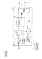
- pointers of a received STS signal are processed to generate a multibit estimate of the frequency difference ( ⁇ f) between the respective local clocks at the originating and terminating nodes of a SONET path.
- ⁇ f frequency difference
- the frequency difference ( ⁇ f) is used to steer a PLL 80 to generate an adjusted clock signal 82 having a frequency f5 which closely approximates the Tx local clock frequency f1.
- the PLL 80 could be cascaded with the desynchronizer PLL 54 of the prior art transparent desynchroniser illustrated in FIG. 2b .
- the frequency f4 of the recovered clock signal 56 generated by the desynchronizer PLL 54 would approximate the frequency f1 of the subscriber traffic, to an arbitrary degree of accuracy.
- a limitation of this approach is that two cascaded Phase Locked Loop circuits are required, which increases the risk of noise in the frequency f4 of the recovered clock signal 56.
- the frequency difference ( ⁇ f) can be combined with the subscriber signal timing value (F) to generate a frequency offset value (FO), which is then used to steer a single desynchronizer PLL 54. Such an embodiment is described below with reference to FIG. 6 .
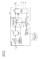
- a terminating node 30a in accordance with the present invention operates in a manner that is generally similar to that described above with reference to FIG. 2b .
- the pointer processor 34 demaps each SPE tributary from a received STS 20, and extracts the timing estimate F.
- the pointer processor 34 also extracts pointer changes, which are filtered by the pointer filter 60 in the manner described above with reference to FIGs. 3 and 4 .
- the frequency difference ( ⁇ f) generated by the pointer filter 60 is used as a "scaling factor" for the timing estimate F, to thereby yield a frequency offset value (FO) which accounts for both the frequency difference between the original subscriber data signal frequency f1 and the Tx reference frequency f2, and between the Tx reference frequency f2 and the Rx reference frequency f3. Accordingly, the difference estimate ( ⁇ f) and the timing estimate F are supplied to a digital combiner 84, which calculates the frequency offset FO.
- the digital combiner 84 comprises a multiplier 86, which normalizes the difference estimate ( ⁇ f) to the timing estimate F, and a digital ADDER 88 which then adds the normalized difference estimate to the timing estimate F, to yield the frequency offset (FO).
- the frequency offset (FO) is then used to steer the desynchronizer Phase locked Loop (PLL) 54, so that the PLL output constitutes a recovered clock signal 56 having a frequency f4 which approximates the original frequency f1 of the subscriber traffic to an arbitrary degree of accuracy.
- PLL Phase locked Loop
- the DPLL 62 is controlled by a state machine 64 to switch between wide and narrow band operation, based on an estimated phase error of the SPE within the received STS frame.
- the bandwidth of the DPLL 62 is controlled via the filter characteristic of the digital filter 72. Accordingly, while a dual bandwidth DPLL is described, those of ordinary skill in the art will appreciate that any desired number of different bandwidths may be implemented, by suitably controlling the digital filter 72.
Abstract
Description
- This invention relates to communications networks, and in particular to a method for digitally processing SONET pointers.
- Within the modern network space, the Synchronous Optical Network (SONET)/Synchronous Digital Hierarchy (SDH) protocol is becoming increasingly popular as a mechanism for data transport. In this respect, SDH is the European equivalent of the SONET transmission standard. Accordingly, all references in this application to SONET should be understood to also refer to SDH.
- A significant amount of SONET/SDH infrastructure has been installed, particularly within the network core. This SONET infrastructure is used to transport asynchronous subscriber signal traffic having differing formats, such as Asynchronous Transfer Mode (ATM), Internet Protocol (IP), etc. In order to facilitate this functionality, various known methods are provided for mapping the asynchronous subscriber traffic into Synchronous Transfer Signal (STS/STM) frames for transport across the SONET infrastructure, and then extracting the subscriber traffic out of the STS to recover the original subscriber signal format.
-
FIG. 1a is a block diagram schematically illustrating principal operations of a conventional transmitting node 2 of an optical communications system. As shown inFIG. 1a , asynchronous subscriber traffic within multiple tributaries 4 is received by the node 2 and buffered in an elastic store 6. The traffic may comprise any arbitrary mix of signals, including DS-1, DS-3 and E1 traffic. Traffic within each tributary 4 is normally buffered in a respective First-In-First-Out (FIFO)buffer 8. The timing of this buffering operation is controlled by adata clock signal 10 having a frequency f1 generated by a tributaryclock recovery circuit 12. A synchronizingframer 14 reads data from eachFIFO 8, and maps the read data into corresponding tributaries of a number of SONET Synchronous Payload Envelopes (SPEs) 16, using a known format such as those defined in the SONET standard. EachSPE 16 is then passed to a channel transmitter (Tx) 18, which inserts the SPEs into an STS frame, and then modulates the STS frame onto anoptical channel carrier 20 for transmission through the optical network. A Txlocal clock 22, which is synchronous with a SONETPrimary Reference 24, generates a respective TXlocal clock signal 26 having a frequency f2, which is used to control operation of the synchronizingframer 14 andchannel Tx 18. - As is known in the art, the number and size of the
SPEs 16 are selected based on the channel line rate. For example, for a channel line rate of 10Gb/s, the synchronizingframer 14 may map subscriber traffic into a set of four STS-48 envelopes. Other combinations may equally be used, such as, for example, eight STS-12 envelopes. - Normally, a respective
buffer fill signal 28 is generated for eachtributary FIFO 8, and used to control the insertion of stuffing bits into the corresponding SPE tributary. - As shown in
FIG. 1b , at the terminatingnode 30, the incoming STS 20 is decoded by a channel receiver (Rx) 32 and processed by apointer processor 34 to demap each SPE tributary from the STS 20. Thus, stuffing bits are stripped out of each tributary, and the remaining subscriber data stored in arespective tributary FIFO 36 of anelastic store 38. An Rxlocal clock signal 40, having a frequency f3 which is preferably referenced to the SONETPrimary Reference 24, is supplied to a desynchronizer Phase locked Loop (PLL) 42. Abuffer fill signal 44 generated by thetributary FIFO 36 is used to steer the Phase locked Loop (PLL) 42, so that the PLL output constitutes a recovereddata clock signal 46 having a frequency f4 which approximates the data rate of the subscriber traffic. As a result, by reading data from thetributary FIFO 36 at a timing of the recovereddata clock 46, adesynchronizer framer 48 can generate a recoveredsubscriber signal 50 in which the original timing is closely approximated. - For cases in which the channel line rate is equal to or greater than the subscriber data rate (i.e. for f1≤f2), the introduction of idle packets to replace "missing" subscriber traffic enables the synchronizing and desynchronizing
framers fill signal 44 of the Rx tributary FIFO buffer 3b tends to vary in a step-wise manner as idle packets are inserted and striped from SPE tributaries. This causes timing jitter in the recoveredsubscriber signal 50. - In most situations, the amount of timing jitter introduced by mapping and demapping asynchronous client signal traffic to and from STS frames does not create any difficulties. However, if the timing of the subscriber signal is critical, such as an HDTV signal or a subscriber-originated SONET signal (e.g. for SONET over SONET applications) the introduced timing jitter can noticeably degrade the quality of the subscriber's signal. Accordingly, there is interest in methods that enable subscriber traffic to be transparently mapped on to SONET STS signals. An important aspect for transparency is to preserve the original timing information of the subscriber signal.
- International Patent Publication
WO 03/032540A 09/972,686 (Roberts et al. 7,023942 on April 4, 2006 . This application teaches a method of rate adapting an asynchronous subscriber signal on to SONET STS frames without incurring waiting time jitter, by measuring the phase and frequency of the (asynchronous) subscriber signal and encoding this information into the frame overhead. Thus, as shown inFIG. 2a , a multi-bit digital timing estimate (F) is calculated (at 52) to indicate the difference between the tributary data rate f1, and the Tx local clock frequency f2. In the embodiment ofFIG. 2a , the timing estimate F is computed as a ratio between f1 and f2. In other embodiments, the timing estimate F may be computed as a phase difference between the subscriber data signal and Tx local clock signal, calculated at the time that a corresponding client data block is mapped into the SPE. In either case, the timing estimate F is supplied to the synchronizingframer 14 and used in place of the tributary fill 28 to control the insertion of stuff bytes into the SPE tributary. The timing estimate F is also inserted into the SPE tributary and conveyed with the subscriber data to the terminatingnode 30. - As shown in
FIG. 2b , at the terminatingnode 30, thepointer processor 34 demaps each SPE tributary, and extracts the timing estimate F. The timing estimate F extracted from the SPE tributary is used in place of the elasticstore fill signal 44 to steer the desynchronizer Phase locked Loop (PLL) 54. Consequently, the PLL output constitutes a recovereddata clock signal 56 having a frequency f4 which more closely approximates the original frequency f1 of the subscriber traffic. As a result, by reading subscriber data from thetributary FIFO 36 at a timing of the recovereddata clock 56, thedesynchronizer framer 48 can generate a recoveredsubscriber signal 50 in which the original timing is substantially restored. - An important attribute of United States Patent Application No.
09/972,686 FIG. 1b ). However, very narrow filtering at thedesynchronizer PLL 42 has the effect of attenuating the subscriber signal's phase variations and hence looses some transparency of the subscriber timing characteristics. United States Patent Application No.09/972,686 desynchronizer PLL 54, which substantially eliminates waiting time jitter. - Another important attribute of United States Patent Application No.
09/972,686 store fill signals nodes 2, 30. This avoids problems due to thefill signals store fill signals 09/972,686 data clock signal 56 at thereceiving node 30. - A limitation of United States Patent Application No.
09/972,686 FIG. 2a ) at the originating node 2, whereas the recovereddata clock signal 56 generated by thedesynchronizer PLL 54 is based on the Rxlocal clock signal 40 at the terminatingnode 30. Ideally, both of the Tx andRx clock signals primary reference 24, and thus will be synchronous. However, the originating and terminatingnodes 2 and 30 may well be situated in different SONET islands, with the result that there may be a frequency difference (Δf) between the Tx and Rxlocal clock signals - The SONET standard provides a method for frequency aligning an incoming SONET signal at a SONET network element using the payload pointers (e.g. the H1, and H2 bytes) within the Transport Overhead (TOH). These pointers provide a positive or negative word stuff of
size 8*N bits for an STS-N signal. For a positive stuff, the start position of data in the Synchronous Payload envelope (SPE) is advanced by 8*N bits, and for a negative stuff, the start position is pushed back by 8*N bits. In principle, the positive and or negative stuff indications that arrive at the terminating SONET node provides a measure of the relative frequency difference between the originating and terminating nodes. - However, a pointer change (i.e. a positive or negative stuff indication) is typically generated when, at an elastic store between the synchronous write and read clocks, the elastic store fill exceeds a predetermined threshold. These pointer changes represent large phase changes in the subscriber data (equivalent to 8*N bits) and occur at a worst case nominal stuffing ratio of zero (see D.L. Duttweiler, "Waiting Time Jitter" Bell System Technical Journal, vol. 51, pp 165-207, January, 1972), which means they can induce a large jitter/wander penalty on the data payload arriving at the terminating
node 30. As well, these pointer changes may have been generated by clock noise or cross-talk, due to the fact that they are driven by an elastic store fill signal. - Various methods have been proposed for reducing the jitter/wander penalty imposed by pointer changes. For example, a common method is to simply allow the large phase step due to the pointer change to occur in the Rx
elastic store 38, and filter this phase step directly into thedesynchronizer PLL 42 using, for example, a low-pass filter 58 (FIG. 1b ). This method directly couples the pointer filtering with the desynchronizer function, which means that the pointer and desynchronizer functions cannot be optimized independently. - The publication "Analysis of Techniques for the Reduction of Jitter Caused by SONET Pointer Adjustments", Kusyk et al., IEEE Transaction on communications, Vol. 42, pp 2036-2050, describes a "pointer leaking" method in which, when a pointer is received, bits corresponding to the pointer are leaked from a first elastic store to a second elastic store (not shown) in order to reduce the slope of the phase change. The second elastic store fill drives the
desynchronizer PLL 42, via alow pass filter 58 in a conventional manner. - The publication "Waiting Time Jitter Reduction by Synchronizer Stuff Threshold Modulation", W.D. Grover et al., Proceedings of IEEE GLOBECOM '87, vol. 1, pp 514-518, describes a threshold modulation method, which involves encoding word stuffing at the synchronizer such that a traditional desynchronizer can largely filter the frequency of the word stuffs. Again this method uses the elastic store fill 44 to drive the
desynchronizer PLL 42, which again implies that the pointer and desynchronizer functions cannot be optimized independently. - As described above, prior art techniques focus on the problem of reducing the jitter imposed on the subscriber signal by pointer changes through the network. Hence the prior art does not address the problem of how to jointly optimize pointer filtering with transparent synchronizer/desynchronizer operation. Nor does the prior art address the question of how to process pointer filters for SONET over SONET applications.
- Accordingly, a method and apparatus capable of accurately estimating the bit rate of subscriber traffic conveyed through a synchronous network between different SONET islands remains highly desirable.
- An object of the present invention is to provide a method and apparatus for accurately estimating the bit rate of subscriber traffic conveyed through a synchronous network between different SONET islands.
- Accordingly, an aspect of the present invention provides a method of estimating a bit rate (f1) of a digital signal conveyed through a SONET network between an originating node and a terminating node. The digital signal received by the originating node is processed to determine a result of a first function of the signal bit rate (f1) and a respective Tx local reference frequency (f2) of the originating node. A result of a second function of the Tx local reference frequency (f2) and a respective Rx local reference frequency (f3) of the terminating node is calculated. Finally, a result of a third function of the respective first and second function results is calculated, to derive an estimate of the signal bit rate (f4) relative to the Rx local reference frequency (f3).
- Preferably the first function comprises any one or more of: a ratio between the signal bit rate (f1) and the Tx local reference frequency (f2); and a difference between the signal bit rate (f1) and the Tx local reference frequency (f2).
- The third function may comprise any one or more of a product and a sum.
- The second function may comprise any one or more of: a ratio between the Tx local reference frequency (f2) and the Rx local reference frequency (f3); and a difference between the Tx local reference frequency (f2) and the Rx local reference frequency (f3).
- The step of determining the second function result may comprise steps of: receiving an STS/STM signal conveyed through the network between the originating and terminating nodes; processing each successive payload pointer of the received STS/STM signal to generate a corresponding pointer parameter; and digitally filtering the pointer parameters to derive the second function result.
- The pointer parameters may be digitally filtered independently of a phase of payload data of the STS/STM signal.
- The step of processing each successive payload pointer may comprise, for each payload pointer, steps of: detecting a respective sign of a pointer change indicated by the payload pointer; and generating the corresponding pointer parameter that is representative of the detected sign.
- The sign of the pointer change may comprise any one of: positive, negative and zero.
- The step of digitally filtering the pointer parameter may comprise steps of: providing a digital phase lock loop (DPLL) for digitally processing the pointer parameters; and controlling a bandwidth of the DPLL.
- The step of controlling the bandwidth of the DPLL may comprise steps of: estimating a phase error of the payload data; comparing the phase error estimate to a predetermined threshold; and selecting the bandwidth of the DPLL based on the comparison result.
- The predetermined threshold may be based on a size of a stuff word.
- The step of selecting the bandwidth of the DPLL may comprise steps of: selecting a narrow bandwidth state of the DPLL when then the phase error is less than the predetermined threshold; and selecting a wide bandwidth state of the DPLL when then the phase error is greater than the predetermined threshold.
- The step of controlling the bandwidth of the DPLL may comprise steps of: estimating a pointer change rate; and controlling the bandwidth of the DPLL based on the estimated pointer change rate.
- A further aspect of the present invention provides a method of estimating a relationship between a Tx local reference frequency (f2) of an originating node and an Rx local reference frequency (f3) of a terminating node of a SONET network. An STS/STM signal is conveyed through the network between the originating node, and received at the and terminating node. Each successive payload pointer of the received STS/STM signal is processed to generate a corresponding pointer parameter. The pointer parameters are filtered to derive an estimate of the relationship between the Tx local reference frequency (f2) and the Rx local reference frequency (f3).
- This method may further comprise a step of adjusting the Rx local reference frequency (f3) using the estimated frequency difference, to generate a recovered clock signal having a frequency (f4) that closely approximates the Tx SONET clock frequency (f2) of the originating node.
- The step of adjusting the local SONET clock frequency may comprise steps of: providing a desynchronizer phase locked loop (PLL) for generating a recovered clock signal based on the local SONET clock frequency; and steering the desynchronizer PLL using the estimated frequency difference.
- This method may further comprise a step of controlling an operation of a pointer processor based on the estimated frequency difference.
- The step of controlling an operation of a pointer processor may comprise steps of: classifying pointer arrival events using the estimated frequency difference; and selecting a method for handling each pointer arrival event based on the classification result.
- The method may further comprise a step of monitoring network clock synchronization quality, based on the estimated frequency difference.
- The method may further comprise a step of monitoring network clock synchronization quality may comprise a step of comparing the estimated frequency difference to a predetermined threshold.
- A still further aspect of the present invention provides a method of desynchronizing asynchronous subscriber traffic conveyed through a synchronous network. An STS/STM signal encapsulating the subscriber traffic is received at a terminating node of the network. The STS signal includes a timing estimate (F) indicative of a frequency difference between a data rate (f1) of the subscriber traffic and a Tx local reference frequency (f2) of an originating node of the network. The encapsulated subscriber traffic is buffered within an elastic store. Each successive payload pointer of the received STS/STM signal is processed to generate a corresponding pointer parameter. These pointer parameters are digitally filtered to derive an estimated relationship (Δf) between the Tx local reference frequency (f2) and an Rx local reference frequency (f3) of the terminating node. The local reference frequency (f3) is then adjusted using the timing estimate (F) and the estimated relationship (Δf), to generate a recovered clock signal having a frequency (f4) that substantially equals the data rate (f1) of the subscriber traffic. Finally, the buffered asynchronous subscriber traffic is read at a timing of the recovered clock signal.
- The step of adjusting the local SONET clock frequency (f3) may comprise steps of: providing a desynchronizer phase locked loop (PLL) for generating the recovered clock signal based on the local reference frequency (f3); deriving a frequency offset value (FO) based on the timing estimate (F) and the estimated relationship between the Tx local reference frequency (f2) and the Rx local reference frequency (f3); and steering the desynchronizer PLL using the frequency offset value (FO).
- There is also provided a system for estimating a relationship between respective local reference frequencies of originating and terminating nodes of a SONET network, the system comprising: a pointer processor for processing each successive payload pointer of an STS signal received at the terminating node to generate a corresponding pointer parameter; and a pointer filter for digitally filtering the pointer parameters to derive an estimated relationship between a Tx local reference frequency (f2) of the originating node and an Rx local reference frequency (f3) of the terminating node.
- The pointer filter may comprise: a digital phase lock loop (DPLL) for digitally processing the pointer parameters; and means for controlling a bandwidth of the DPLL.
- The means for controlling a bandwidth of the DPLL may comprise: a phase error calculator for estimating a phase error of an SPE of the STS signal; and a state machine for: comparing the phase error estimate to a predetermined threshold; and selecting the bandwidth of the DPLL based on the comparison result.
- The system may further comprise: a desynchronizer phase locked loop (PLL) for generating a recovered clock signal based on the Rx local frequency (f3); and means for steering the desynchronizer PLL using the estimated relationship so as to generate a recovered clock signal having a frequency (f4) that closely approximates the Tx local reference frequency (f2) of the originating node.
- There is also provided a system for desynchronizing asynchronous subscriber traffic conveyed through a synchronous network, the system comprising: a receiver for receiving an STS signal encapsulating the subscriber traffic at a terminating node, the STS signal including a timing estimate (F) indicative of a first relationship between a data rate (f1) of the subscriber traffic and a Tx local reference frequency (f2) of an originating node; an elastic store for buffering the encapsulated subscriber traffic; a pointer processor for processing each successive payload pointer of the received STS signal to generate a corresponding pointer parameter; a pointer filter for digitally filtering the pointer parameters to derive an estimated second relationship between a Tx local reference frequency (f2) of the originating node and an Rx local reference frequency (f3) of the terminating node; means for adjusting the Rx local reference frequency (f3) using the first and second relationships, to generate a recovered clock signal having a frequency (f4) that substantially equals the data rate (f1) of the subscriber traffic; and a desynchronizer framer for reading the buffered subscriber traffic at a timing of the recovered clock signal.
- The pointer filter may comprise: a digital phase lock loop (DPLL) for digitally processing the pointer change indications; and means for controlling a bandwidth of the DPLL.
- The means for controlling a bandwidth of the DPLL may comprise: a phase error calculator for estimating a phase error of an SPE of the STS signal; and a state machine for: comparing the phase error estimate to a predetermined threshold; and controlling the bandwidth of the DPLL based on the comparison result.
- The means for adjusting the local SONET clock frequency (f3) may comprise: a digital combiner for deriving a frequency offset value (FO) based on the timing estimate (F) and the estimated second relationship; and a desynchronizer phase locked loop (PLL) for generating the recovered clock signal based on the Rx local reference frequency (f3) and the frequency offset value (FO).
- An important application for transparent signal transport is SONET over SONET, in which a SONET signal is encapsulated transparently over another SONET signal. For example, the emerging G. Modem standard (G.709 standard) utilizes an STS-192 signal, which is encapsulated within ODU-2 (G.709 standard), which, in turn, is encapsulated within an STS-204 for transport across SONET infrastructure. In this scenario, any pointer changes in the STS-204 line overhead must be filtered in order to desynchronize the STS-192 embedded in the ODU-2, and preserve the original STS-192 phase and timing. The present invention enables this operation, even across differing SONET islands.
- Further features and advantages of the present invention will become apparent from the following detailed description, taken in combination with the appended drawings, in which:
-
Figs. 1a and1b are block diagrams schematically illustrating conventional originating and terminating nodes, respectively, of an optical communications network; -
Figs. 2a and2b are block diagrams schematically illustrating originating and terminating nodes, respectively, known from United States Patent Application No.09/972,686 -
FIG. 3 is a block diagram schematically illustrating principal elements of a pointer filter in accordance with the present invention; -
FIG. 4 is a state diagram schematically illustrating operating modes of the state machine of the embodiment ofFIG. 3 ; -
FIG. 5 is a block diagram schematically illustrating a terminating node employing a pointer filter in accordance with the embodiment ofFIG. 3 used to steer a phase locked loop; and -
FIG. 6 is a block diagram schematically illustrating the terminating node ofFIG. 2b employing a pointer filter in accordance with the embodiment ofFIG. 3 . - It will be noted that throughout the appended drawings, like features are identified by like reference numerals.
- The present invention provides a method an apparatus for accurately estimating the bit rate of subscriber traffic received through a synchronous network having two or more SONET islands. Embodiments of the invention are described below with reference to
FIGs. 3-5 . - In general, the present invention operates by filtering pointer parameters to estimate a relationship between the Tx reference frequency (f2) at an originating node and the Rx reference frequency (f3) at the terminating node. This relationship can then be used for various purposes, such as, for example, estimating the bit rate of subscriber traffic relative to the Rx reference frequency (f3). Pointer parameters may take any of a variety of forms, such as, for example, payload pointer changes, or pointer rates. As may be appreciated, the relationship between the Tx reference frequency (f2) and the Rx reference frequency (f3) may be represented in various ways, depending on how the information is to be used. Exemplary formulations include: a frequency difference (Δf) between the Tx and Rx clock frequencies; a phase difference (ΔP); a ratio (e.g.


- As shown in
FIG. 3 , the present invention can be implemented using apointer filter 60 coupled to receive payload pointer changes from thepointer processor 34 of the terminatingnode 30. Thepointer filter 60 processes the payload pointer changes to generate a multi-bit estimate of the frequency difference (Δf) between the Tx and Rx local clock signals. Operation of thepointer filter 60 to calculate the frequency difference (Δf) between the Tx and Rx local clock signals is described below. - As is known in the art, the Synchronous Payload Envelope (SPE) is permitted to float within the STS frame. The starting position of the SPE within the STS frame payload capacity is denoted by a payload pointer located in the H1 and H2 bytes of the line overhead (LOH). As the frame traverses the network, differences between the frame rate and the SPE rate (for example, due to a SONET reference frequency difference between SONET islands) will result in periodic changes in the payload pointer values. The presence of a pointer change can be identified by the value of the "New Data Flag" (NDF) located in bits 1-4 of the payload pointer. The sign of the change is indicated by inversion of either
bits 7, 9, 11, 13 and 15 (the I-bits of the payload pointer) in the case of a positive change, orbits - As each STS frame arrives at the terminating
node 30, thepointer processor 34 operates to examine the payload pointers within the TOH and forward corresponding pointer change information to thepointer filter 60. In the illustrated embodiment, if the NDF value indicates no change in the payload pointer, then thepointer processor 34 sends a "Zero" indication to thepointer filter 60. On the other hand, if the NDF value indicates that the payload pointer has changed, thenpointer processor 34 determines the sign of the change (e.g. positive or negative) and sends a corresponding indication to thepointer filter 60. This means that thepointer filter 60 will receive a respective pointer change indication (e.g. positive, negative or zero) for each payload pointer received by thepointer processor 34. - As shown in
FIG. 3 , thepointer filter 60 generally comprises a digital phase locked loop (DPLL) 62 controlled by astate machine 64, and adigital divider 66. The output of thedigital divider 66 is a multi-bit low noise estimate of the frequency difference (Δf). - The
DPLL 62 is formed by adigital ADDER 68, aphase error calculator 70, and adigital filter block 72 controlled by thestate machine 64. Thedigital ADDER 68 operates to add the pointer change indications received from thepointer processor 34 to the negative of the digital filter output. The resulting digital signal is supplied to thephase error calculator 70, which computes an estimate of the phase error (PE) of the SPE using, for example, an operator of the form
digital ADDER 68. - The phase error estimate (PE) is supplied to the
state machine 64 and thedigital filter 72. Thestate machine 64 uses the phase error estimate PE for managing state transitions, as will be described below. Thedigital filter 72 operates to filter the phase error estimate (PE) using, for example, an operator of the form: -

- where z is the current phase error estimate (PE), and (n) and (g) are parameters supplied by the
state machine 64. As may be appreciated, the parameters n and g determine the filter characteristic, and thereby the effective bandwidth of theDPLL 62. Thus thestate machine 64 can operate to select wide or narrow bandwidth operating modes of theDPLL 62, as required, by selecting appropriate values for the parameters n and g. If desired, the required parameter values (for both wide and narrow bandwidth operating modes) can be predetermined and stored in a memory (not shown) for use during run-time of thestate machine 64. - The output of the
digital filter 72 is a multi-bit error value that is directly proportional to the rate of "slippage" of the SPE within the STS frame as it traverses the optical network, measured in bits-per-pointer (or, equivalently, bits-per-tributary). This error value can be normalized (at 66) to a low noise estimate of the frequency difference (Δf) by dividing the error value by the tributary length (in bits) . - As may be appreciated, in order to properly account for frequency differences between SONET islands, the
DPLL 62 must be able to acquire the SPE frequency within a comparatively wide pull-in range (e.g., on the order of about 10 Hz). However, once the SPE frequency has been acquired, theDPLL 62 must be able to maintain phase lock within a range of about 0.0025 Hz, in order to satisfy standard MTIE ANSI specifications for normal operation. - In general, the
state machine 64 operates to select the appropriate DPLL bandwidth based on the phase error estimate (PE) and a frequency estimate (FE) derived from the pointer changes received from thepointer processor 34. The frequency estimate (FE) may be calculated (at 74) using an equation of the form
elastic store FIFO 36. If desired, the frequency estimate (FE) can be recalculated for each successive payload pointer, which means that the value will be updated for eachtributary. Jitter in the frequency estimate (FE) value can be reduced by using an average count value calculated over a desired number of successive pointer changes. - As shown in
FIG. 4 , thestate machine 64 transitions between awide bandwidth state 76 and anarrow bandwidth state 78, depending on the value of the phase error estimate (PE), and a timer value C. A timer 80 (Fig. 3 ) is used to ensure that thestate machine 64 remains in one state for a predetermined minimum period of time (such as, for example, Co=20 seconds) before transitioning to the other state. This is advantageous in that it prevents erroneous operation of thestate machine 64 rapidly oscillating between states. - During initialization (e.g. during system start-up), the
state machine 64 enters theWide bandwidth state 78 in order to acquire the SPE frequency and pull the phase error estimate (PE) close to zero. While the phase error estimate (PE) is equal to or greater than a predetermined threshold (such as, for example, the stuff word size L) thestate machine 64 remains in theWide bandwidth state 78. Within theWide bandwidth state 78, thestate machine 64 selects appropriate "wide bandwidth" parameter values n and g, and supplies these values to thedigital filter 72 of theDPLL 62, to yield a DPLL bandwidth of, for example, about 10Hz. Under these conditions, the impulse response of theDPLL 62 satisfies the short term MTIE specification for phase transients, while the jitter performance meets the network limit requirements. - When the phase error estimate (PE) drops below the predetermined threshold (e.g. the stuff word size L), the
state machine 64 transitions to thenarrow bandwidth state 78. If the current timer value C is greater than the predetermined limit Co (e.g. 20 seconds), thetimer 80 is reset to C=0. In addition, the input state is set to zero, and the feedback state is set to the frequency estimate (FE). - Within the
narrow bandwidth state 78, thestate machine 64 selects appropriate "narrow bandwidth" parameter values n and g, and supplies these values to the digital filter 728 of theDPLL 62, to yield a DPLL bandwidth of, for example, about 0.0025 Hz. With this arrangement, the impulse response of theDPLL 62 meets the short term MTEI ANSI specification for normal operation. As long as the phase error estimate (PE) remains below the threshold, thestate machine 64 will remain in thenarrow bandwidth state 78. If the phase error estimate (PE) rises above the threshold, which may, for example, occur during a change in the SONET Primary Reference frequency, the state machine will return to thewide bandwidth state 76 in order to reacquire the SPE rate. - An advantageous feature of the present invention is that pointer changes are digitally processed independently of the desynchronizer circuit (formed by the
pointer processor 34,elastic store 38,desynchronizer PLL 54 and desynchronizer framer 48). Digitally processing the pointer changes independently of the subscriber data enables this separation. A benefit of this separation is that it enables independent optimization of pointer and data desynchronization functions. This attribute is significant since the performance requirements for the pointer changes and data desynchronization are typically different, and the nature of degradations are unique. An additional benefit of the present invention is that, because pointer changes are digitally filtered directly, the data elastic store fill signal with its associated hazards of clock noise, cross-talk, and data patterning is avoided. - The solution of the present invention also enables the important advantage that two different bandwidths for pointer change processing and data synchronization can be maintained simultaneously. Thus, for example, bandwidths of less than 100 mHz can be maintained in the
pointer filter DPLL 62 to meet the stringent SONET standards (e.g. for SONET over SONET applications), while thedesynchronizer PLL 54 bandwidth can be very wide to facilitate transparency. - As discussed in detail above, pointers of a received STS signal are processed to generate a multibit estimate of the frequency difference (Δf) between the respective local clocks at the originating and terminating nodes of a SONET path. This information can be used in various ways, including (without limitation):
- the frequency difference (Δf) can be provided to a network management system (not shown) and used for monitoring network clock synchronization quality. For example. the frequency difference (Δf) can be compared to a predetermined threshold, and an alarm raised if the threshold is exceeded;
- the frequency difference (Δf) can be used in combination with the frequency estimate (FE) and estimated phase error (PE) to enable intelligent handling of payload pointers by the pointer processor. For example, pointer arrival events can be classified (e.g. as being due to the frequency difference Δf or burst effects such as SONET primary reference changes etc.) and handled by different digital signal processing methods based on the classification result; and
- the frequency difference (Δf) can be used to adjust the Rx local reference frequency f3, and thereby improve network transparency.
- In the embodiment of
FIG. 5 , the frequency difference (Δf) is used to steer aPLL 80 to generate an adjustedclock signal 82 having a frequency f5 which closely approximates the Tx local clock frequency f1. If desired, thePLL 80 could be cascaded with thedesynchronizer PLL 54 of the prior art transparent desynchroniser illustrated inFIG. 2b . With this arrangement, the frequency f4 of the recoveredclock signal 56 generated by thedesynchronizer PLL 54 would approximate the frequency f1 of the subscriber traffic, to an arbitrary degree of accuracy. A limitation of this approach is that two cascaded Phase Locked Loop circuits are required, which increases the risk of noise in the frequency f4 of the recoveredclock signal 56. Alternatively, the frequency difference (Δf) can be combined with the subscriber signal timing value (F) to generate a frequency offset value (FO), which is then used to steer asingle desynchronizer PLL 54. Such an embodiment is described below with reference toFIG. 6 . - As shown in
FIG. 6 , a terminating node 30a in accordance with the present invention operates in a manner that is generally similar to that described above with reference toFIG. 2b . Thus, thepointer processor 34 demaps each SPE tributary from a receivedSTS 20, and extracts the timing estimate F. However, thepointer processor 34 also extracts pointer changes, which are filtered by thepointer filter 60 in the manner described above with reference toFIGs. 3 and4 . In the illustrated embodiment, the frequency difference (Δf) generated by thepointer filter 60 is used as a "scaling factor" for the timing estimate F, to thereby yield a frequency offset value (FO) which accounts for both the frequency difference between the original subscriber data signal frequency f1 and the Tx reference frequency f2, and between the Tx reference frequency f2 and the Rx reference frequency f3. Accordingly, the difference estimate (Δf) and the timing estimate F are supplied to adigital combiner 84, which calculates the frequency offset FO. - As shown in
FIG. 6 , thedigital combiner 84 comprises amultiplier 86, which normalizes the difference estimate (Δf) to the timing estimate F, and adigital ADDER 88 which then adds the normalized difference estimate to the timing estimate F, to yield the frequency offset (FO). - The frequency offset (FO) is then used to steer the desynchronizer Phase locked Loop (PLL) 54, so that the PLL output constitutes a recovered
clock signal 56 having a frequency f4 which approximates the original frequency f1 of the subscriber traffic to an arbitrary degree of accuracy. As a result, by reading subscriber data from thetributary FIFO 36 at a timing of the recoveredclock 56, thedesynchronizer framer 48 can generate a recoveredsubscriber signal 50 in which the original timing is restored, again, to an arbitrary degree of accuracy. - In the foregoing description, the
DPLL 62 is controlled by astate machine 64 to switch between wide and narrow band operation, based on an estimated phase error of the SPE within the received STS frame. As mentioned above, the bandwidth of theDPLL 62 is controlled via the filter characteristic of thedigital filter 72. Accordingly, while a dual bandwidth DPLL is described, those of ordinary skill in the art will appreciate that any desired number of different bandwidths may be implemented, by suitably controlling thedigital filter 72. - The embodiment(s) of the invention described above is(are) intended to be exemplary only. The scope of the invention is therefore intended to be limited solely by the scope of the appended claims.
Claims (13)
- A method of estimating a bit rate (f1) of a digital signal conveyed through a SONET/SDH network between an originating node and a terminating node, the method comprising steps of:receiving the digital signal at the originating node, and calculating a subscriber timing value indicative of a relationship between the signal bit rate (f1) and a respective Tx local reference frequency (f2) of the originating node;estimating a relationship between the Tx local reference frequency (f2) and a respective Rx local reference frequency (f3) of the terminating node; andderiving an estimate of the signal bit rate (f4) relative to the Rx local reference frequency (f3), based on the subscriber timing value and the estimated relationship between the Tx local reference frequency (f2) and the respective Rx local reference frequency (f3) of the terminating node.
- A method as claimed in claim 1, wherein the subscriber timing value comprises any one or more of:a ratio between the signal bit rate (f1) and the Tx local reference frequency (f2); anda difference between the signal bit rate (f1) and the Tx local reference frequency (f2).
- A method as claimed in claim 1, wherein the step of deriving an estimate of the signal bit rate (f4) comprises calculating any one or more of a product and a sum
- A method as claimed in claim 1, wherein the estimated relationship between the Tx local reference frequency (f2) and the respective Rx local reference frequency (f3) of the terminating node comprises any one or more of:a ratio between the Tx local reference frequency (f2) and the Rx local reference frequency (f3); anda difference between the Tx local reference frequency (f2) and the Rx local reference frequency (f3).
- A method as claimed in claim 4, wherein the step of estimating the relationship comprises steps of:receiving an STS/STM signal conveyed through the network between the originating and terminating nodes;processing each successive payload pointer of the received STS/STM signal to generate a corresponding pointer parameter; anddigitally filtering the pointer parameters to derive the second function result.
- A method as claimed in claim 4, wherein the pointer parameters are digitally filtered independently of a phase of payload data of the STS/STM signal.
- A method as claimed in claim 6, wherein the step of processing each successive payload pointer comprises, for each payload pointer, steps of:detecting a respective sign of a pointer change indicated by the payload pointer; andgenerating the corresponding pointer parameter that is representative of the detected sign.
- A method as claimed in claim 7, wherein the sign of the pointer change comprises any one of: positive, negative and zero.
- A method as claimed in claim 4, wherein the step of digitally filtering the pointer parameter comprises steps of:providing a digital phase lock loop (DPLL) for digitally processing the pointer parameters; andcontrolling a bandwidth of the DPLL.
- A method as claimed in claim 9, wherein the step of controlling the bandwidth of the DPLL comprises steps of:estimating a phase error of the payload data;comparing the phase error estimate to a predetermined threshold; andselecting the bandwidth of the DPLL based on the comparison result.
- A method as claimed in claim 10, wherein the predetermined threshold is based on a size of a stuff word.
- A method as claimed in claim 10, wherein the step of selecting the bandwidth of the DPLL comprises steps of:selecting a narrow bandwidth state of the DPLL when then the phase error is less than the predetermined threshold; andselecting a wide bandwidth state of the DPLL when then the phase error is greater than the predetermined threshold.
- A method as claimed in claim 9, wherein the step of controlling the bandwidth of the DPLL comprises steps of:estimating a pointer change rate; andcontrolling the bandwidth of the DPLL based on the estimated pointer change rate.
Applications Claiming Priority (2)
| Application Number | Priority Date | Filing Date | Title |
|---|---|---|---|
| US10/609,562 US7369578B2 (en) | 2003-07-01 | 2003-07-01 | Digital processing of SONET pointers |
| EP04394039A EP1494377A1 (en) | 2003-07-01 | 2004-07-01 | Digital processing of SONET pointers |
Related Parent Applications (2)
| Application Number | Title | Priority Date | Filing Date |
|---|---|---|---|
| EP04394039.4 Division | 2004-07-01 | ||
| EP04394039A Division EP1494377A1 (en) | 2003-07-01 | 2004-07-01 | Digital processing of SONET pointers |
Publications (2)
| Publication Number | Publication Date |
|---|---|
| EP2124365A2 true EP2124365A2 (en) | 2009-11-25 |
| EP2124365A3 EP2124365A3 (en) | 2010-10-27 |
Family
ID=33435364
Family Applications (3)
| Application Number | Title | Priority Date | Filing Date |
|---|---|---|---|
| EP09168625A Withdrawn EP2124364A3 (en) | 2003-07-01 | 2004-07-01 | digital processing of SONET pointers |
| EP09168627A Withdrawn EP2124365A3 (en) | 2003-07-01 | 2004-07-01 | Digital processing of SONET pointers |
| EP04394039A Withdrawn EP1494377A1 (en) | 2003-07-01 | 2004-07-01 | Digital processing of SONET pointers |
Family Applications Before (1)
| Application Number | Title | Priority Date | Filing Date |
|---|---|---|---|
| EP09168625A Withdrawn EP2124364A3 (en) | 2003-07-01 | 2004-07-01 | digital processing of SONET pointers |
Family Applications After (1)
| Application Number | Title | Priority Date | Filing Date |
|---|---|---|---|
| EP04394039A Withdrawn EP1494377A1 (en) | 2003-07-01 | 2004-07-01 | Digital processing of SONET pointers |
Country Status (3)
| Country | Link |
|---|---|
| US (1) | US7369578B2 (en) |
| EP (3) | EP2124364A3 (en) |
| CA (1) | CA2472691C (en) |
Families Citing this family (11)
| Publication number | Priority date | Publication date | Assignee | Title |
|---|---|---|---|---|
| US7440533B2 (en) * | 2003-01-17 | 2008-10-21 | Applied Micro Circuits Corporation | Modulated jitter attenuation filter |
| US7443888B2 (en) * | 2003-10-02 | 2008-10-28 | Ciena Corporation | Transparent sub-wavelength network |
| US7606269B1 (en) * | 2004-07-27 | 2009-10-20 | Intel Corporation | Method and apparatus for detecting and managing loss of alignment in a virtually concatenated group |
| JP2007096822A (en) * | 2005-09-29 | 2007-04-12 | Fujitsu Ltd | Signal multiplxer and its stuff control method |
| JP4729049B2 (en) * | 2005-12-22 | 2011-07-20 | 日本電信電話株式会社 | Optical transmitter |
| JP4733766B2 (en) * | 2007-06-08 | 2011-07-27 | 富士通株式会社 | Jitter control device |
| US8005368B2 (en) * | 2007-12-05 | 2011-08-23 | Ciena Corporation | Signal equalizer in a coherent optical receiver |
| US8184760B2 (en) * | 2008-09-02 | 2012-05-22 | Taiwan Semiconductor Manufacturing Company, Ltd. | Adaptive elastic buffer for communications |
| US8237861B2 (en) * | 2009-10-13 | 2012-08-07 | Himax Media Solutions, Inc. | Video horizontal synchronizer |
| US9596035B2 (en) | 2011-10-05 | 2017-03-14 | Ciena Corporation | Minimum variance carrier recovery with increased phase noise tolerance |
| US10404447B1 (en) * | 2018-06-26 | 2019-09-03 | Microsemi Semiconductor Ulc | Clock recovery device with state machine controller |
Citations (1)
| Publication number | Priority date | Publication date | Assignee | Title |
|---|---|---|---|---|
| WO2003032540A2 (en) | 2001-10-09 | 2003-04-17 | Nortel Networks Limited | Method and apparatus for digital data synchronization |
Family Cites Families (7)
| Publication number | Priority date | Publication date | Assignee | Title |
|---|---|---|---|---|
| US5313502A (en) | 1990-05-09 | 1994-05-17 | Ant Nachrichtentechnik Gmbh | Arrangement for imaging a useful signal from the frame of a first digital signal at a first bite rate into the frame of a second digital signal at a second bite rate |
| GB9012436D0 (en) | 1990-06-04 | 1990-07-25 | Plessey Telecomm | Sdh rejustification |
| CA2059692C (en) * | 1991-01-28 | 2004-11-16 | Peter J. Kniskern | Pneumoccoccal polysaccharide conjugate vaccine |
| US5268935A (en) * | 1991-12-20 | 1993-12-07 | At&T Bell Laboratories | Synchronous digital signal to asynchronous digital signal desynchronizer |
| US5436937A (en) * | 1993-02-01 | 1995-07-25 | Motorola, Inc. | Multi-mode digital phase lock loop |
| US5463351A (en) * | 1994-09-29 | 1995-10-31 | Motorola, Inc. | Nested digital phase lock loop |
| US6229863B1 (en) * | 1998-11-02 | 2001-05-08 | Adc Telecommunications, Inc. | Reducing waiting time jitter |
-
2003
- 2003-07-01 US US10/609,562 patent/US7369578B2/en not_active Expired - Fee Related
-
2004
- 2004-06-29 CA CA2472691A patent/CA2472691C/en active Active
- 2004-07-01 EP EP09168625A patent/EP2124364A3/en not_active Withdrawn
- 2004-07-01 EP EP09168627A patent/EP2124365A3/en not_active Withdrawn
- 2004-07-01 EP EP04394039A patent/EP1494377A1/en not_active Withdrawn
Patent Citations (2)
| Publication number | Priority date | Publication date | Assignee | Title |
|---|---|---|---|---|
| WO2003032540A2 (en) | 2001-10-09 | 2003-04-17 | Nortel Networks Limited | Method and apparatus for digital data synchronization |
| US7023942B1 (en) | 2001-10-09 | 2006-04-04 | Nortel Networks Limited | Method and apparatus for digital data synchronization |
Non-Patent Citations (3)
| Title |
|---|
| D.L. DUTTWEILER: "Waiting Time Jitter", BELL SYSTEM TECHNICAL JOURNAL, vol. 51, January 1972 (1972-01-01), pages 165 - 207 |
| KUSYK ET AL.: "Analysis of Techniques for the Reduction of Jitter Caused by SONET Pointer Adjustments", IEEE TRANSACTION ON COMMUNICATIONS, vol. 42, pages 2036 - 2050 |
| W.D. GROVER ET AL.: "Waiting Time Jitter Reduction by Synchronizer Stuff Threshold Modulation", PROCEEDINGS OF IEEE GLOBECOM '87, vol. 1, pages 514 - 518 |
Also Published As
| Publication number | Publication date |
|---|---|
| US20050002403A1 (en) | 2005-01-06 |
| EP2124365A3 (en) | 2010-10-27 |
| US7369578B2 (en) | 2008-05-06 |
| CA2472691A1 (en) | 2005-01-01 |
| CA2472691C (en) | 2015-08-11 |
| EP2124364A2 (en) | 2009-11-25 |
| EP2124364A3 (en) | 2010-10-27 |
| EP1494377A1 (en) | 2005-01-05 |
Similar Documents
| Publication | Publication Date | Title |
|---|---|---|
| US5956347A (en) | Digital telecommunications transmission systems | |
| EP0473338B1 (en) | Bit synchronization with elastic memory | |
| JP3092352B2 (en) | Apparatus and method for desynchronized SONET with DS-N signal | |
| US7369578B2 (en) | Digital processing of SONET pointers | |
| US20070019772A1 (en) | Timeshared jitter attenuator in multi-channel mapping applications | |
| US7023942B1 (en) | Method and apparatus for digital data synchronization | |
| US20020186719A1 (en) | Pointer adjustment wander and jitter reduction apparatus for a desynchronizer | |
| US6351508B1 (en) | Phase/frequency detector for dejitter applications | |
| EP0960494B1 (en) | Synchronisation in an atm over stm transmission system | |
| US7940806B1 (en) | Synchronous payload envelope mapping without pointer adjustments | |
| US5539785A (en) | Jitter/wander reduction circuit for pulse-stuffed, synchronized digital communications | |
| US20030227988A1 (en) | Jitter and wander reduction apparatus | |
| US5703915A (en) | Transmission system and multiplexing/demultiplexing equipment involving a justifiable bit stream | |
| JPH11266221A (en) | Payload relative position change request device and transmitter provided with the same | |
| US7599400B2 (en) | Methods and systems for reducing waiting-time jitter | |
| KR100365728B1 (en) | Apparatus and method of desynchronous data transmission for jitter/wander reduction | |
| US7715443B1 (en) | Boundary processing between a synchronous network and a plesiochronous network | |
| EP0674407B1 (en) | Complementary justification | |
| US5883900A (en) | Telecommunications transmission | |
| Antry et al. | Minimization of the accumulated phase change at the input of SDH/SONET desynchronizers | |
| El-Ela et al. | Desynchronizer circuit in SDH system using digital PLL | |
| Sholander et al. | The impact of mapping wander on the performance of SDH AU-4 and TU-3 uniform pointer processors | |
| KR20010113421A (en) | Improved pointer adjustment synchronization system | |
| KR20040057018A (en) | Synchronization system for synchronous multiplexer | |
| JPH07143088A (en) | Data separation and output circuit |
Legal Events
| Date | Code | Title | Description |
|---|---|---|---|
| PUAI | Public reference made under article 153(3) epc to a published international application that has entered the european phase |
Free format text: ORIGINAL CODE: 0009012 |
|
| AC | Divisional application: reference to earlier application |
Ref document number: 1494377 Country of ref document: EP Kind code of ref document: P |
|
| AK | Designated contracting states |
Kind code of ref document: A2 Designated state(s): DE FR GB |
|
| PUAL | Search report despatched |
Free format text: ORIGINAL CODE: 0009013 |
|
| AK | Designated contracting states |
Kind code of ref document: A3 Designated state(s): DE FR GB |
|
| AX | Request for extension of the european patent |
Extension state: AL HR LT LV MK |
|
| RAP1 | Party data changed (applicant data changed or rights of an application transferred) |
Owner name: CIENA LUXEMBOURG S.A.R.L. |
|
| STAA | Information on the status of an ep patent application or granted ep patent |
Free format text: STATUS: THE APPLICATION IS DEEMED TO BE WITHDRAWN |
|
| 18D | Application deemed to be withdrawn |
Effective date: 20110428 |