EP2124335B1 - Method for optimising a multi-stage filter bank and corresponding filter bank and hearing aid - Google Patents
Method for optimising a multi-stage filter bank and corresponding filter bank and hearing aid Download PDFInfo
- Publication number
- EP2124335B1 EP2124335B1 EP09159307.9A EP09159307A EP2124335B1 EP 2124335 B1 EP2124335 B1 EP 2124335B1 EP 09159307 A EP09159307 A EP 09159307A EP 2124335 B1 EP2124335 B1 EP 2124335B1
- Authority
- EP
- European Patent Office
- Prior art keywords
- filter bank
- input
- filter
- group delay
- bank
- Prior art date
- Legal status (The legal status is an assumption and is not a legal conclusion. Google has not performed a legal analysis and makes no representation as to the accuracy of the status listed.)
- Active
Links
- 238000000034 method Methods 0.000 title claims description 16
- 238000005070 sampling Methods 0.000 claims description 9
- 238000003786 synthesis reaction Methods 0.000 claims description 5
- 230000015572 biosynthetic process Effects 0.000 claims description 4
- 230000001186 cumulative effect Effects 0.000 claims description 2
- 238000012545 processing Methods 0.000 description 13
- 238000005457 optimization Methods 0.000 description 8
- OVBPIULPVIDEAO-LBPRGKRZSA-N folic acid Chemical compound C=1N=C2NC(N)=NC(=O)C2=NC=1CNC1=CC=C(C(=O)N[C@@H](CCC(O)=O)C(O)=O)C=C1 OVBPIULPVIDEAO-LBPRGKRZSA-N 0.000 description 7
- 230000006870 function Effects 0.000 description 7
- 230000006872 improvement Effects 0.000 description 6
- 238000005265 energy consumption Methods 0.000 description 4
- 238000004458 analytical method Methods 0.000 description 3
- 238000010586 diagram Methods 0.000 description 3
- 230000008901 benefit Effects 0.000 description 2
- 210000000988 bone and bone Anatomy 0.000 description 2
- 238000000354 decomposition reaction Methods 0.000 description 2
- 238000013461 design Methods 0.000 description 2
- 210000000613 ear canal Anatomy 0.000 description 2
- 238000011156 evaluation Methods 0.000 description 2
- 230000008569 process Effects 0.000 description 2
- 230000009467 reduction Effects 0.000 description 2
- 230000005236 sound signal Effects 0.000 description 2
- 208000032041 Hearing impaired Diseases 0.000 description 1
- 230000003321 amplification Effects 0.000 description 1
- 238000007796 conventional method Methods 0.000 description 1
- 230000001955 cumulated effect Effects 0.000 description 1
- 230000001934 delay Effects 0.000 description 1
- 230000001419 dependent effect Effects 0.000 description 1
- 238000011161 development Methods 0.000 description 1
- 238000010252 digital analysis Methods 0.000 description 1
- 210000000883 ear external Anatomy 0.000 description 1
- 238000001914 filtration Methods 0.000 description 1
- 230000006698 induction Effects 0.000 description 1
- 238000011835 investigation Methods 0.000 description 1
- 238000009828 non-uniform distribution Methods 0.000 description 1
- 238000003199 nucleic acid amplification method Methods 0.000 description 1
- 230000010355 oscillation Effects 0.000 description 1
- 230000002265 prevention Effects 0.000 description 1
- 230000003595 spectral effect Effects 0.000 description 1
- 230000000638 stimulation Effects 0.000 description 1
- 238000011410 subtraction method Methods 0.000 description 1
- 210000003454 tympanic membrane Anatomy 0.000 description 1
Images


Classifications
-
- H—ELECTRICITY
- H03—ELECTRONIC CIRCUITRY
- H03H—IMPEDANCE NETWORKS, e.g. RESONANT CIRCUITS; RESONATORS
- H03H17/00—Networks using digital techniques
- H03H17/02—Frequency selective networks
- H03H17/0248—Filters characterised by a particular frequency response or filtering method
- H03H17/0264—Filter sets with mutual related characteristics
- H03H17/0266—Filter banks
Definitions
- the present invention relates to a method for optimizing a structure of a multi-stage filter bank having an input side and an output side filter bank based on a given filter type, wherein the input side filter bank has the input channel number as the variable first parameter and an oversampling factor as the variable second parameter.
- the present invention relates to a multi-stage filter bank, the structure of which is obtained by means of a method above.
- the present invention also relates to a hearing device with such a multi-stage filter bank.
- hearing device is understood here to mean any sound-emitting device which can be worn in or on the ear, in particular a hearing device, a headset, headphones and the like.
- Hearing aids are portable hearing aids that are used to care for the hearing impaired.
- different types of hearing aids such as behind-the-ear hearing aids (BTE), hearing aid with external receiver (RIC: receiver in the canal) and in-the-ear hearing aids (IDO), e.g. Concha hearing aids or canal hearing aids (ITE, CIC).
- BTE behind-the-ear hearing aids
- RIC hearing aid with external receiver
- IDO in-the-ear hearing aids
- ITE canal hearing aids
- the hearing aids listed by way of example are worn on the outer ear or in the ear canal.
- bone conduction hearing aids, implantable or vibrotactile hearing aids are also available on the market. The stimulation of the damaged hearing takes place either mechanically or electrically.
- Hearing aids have in principle as essential components an input transducer, an amplifier and an output transducer.
- the input transducer is usually a sound receiver, z. As a microphone, and / or an electromagnetic receiver, for. B. an induction coil.
- the output transducer is usually as an electroacoustic transducer, z. As miniature speaker, or as an electromechanical transducer, z. B. bone conduction, realized.
- the amplifier is usually integrated in a signal processing unit. This basic structure is in FIG. 1 shown using the example of a behind-the-ear hearing aid. In a hearing aid housing 1 for carrying behind the ear, one or more microphones 2 for receiving the sound from the environment are installed.
- a signal processing unit 3 which is also integrated in the hearing aid housing 1, processes the microphone signals and amplifies them.
- the output signal of the signal processing unit 3 is transmitted to a loudspeaker or earpiece 4, which outputs an acoustic signal.
- the sound is optionally transmitted via a sound tube, which is fixed with an earmold in the ear canal, to the eardrum of the device carrier.
- the power supply of the hearing device and in particular the signal processing unit 3 is effected by a likewise integrated into the hearing aid housing 1 battery. 5
- Sound signals recorded by one or more microphones of a hearing aid are usually decomposed into subband signals for further processing.
- a subsequent resynthesis of the manipulated subband signals can be carried out by means of a digital synthesis filter bank (SFB).
- FFB frequency-selective digital analysis filter bank
- High-quality filter banks in hearing aids are subject to certain requirements. For example, in the bottommost bands, a channel bandwidth of about 250 Hz is needed. Otherwise, the band gap should be based on the Bark scale. Furthermore, a channel number of at least 22 is desirable. Disturbance due to aliasing should be below 60dB. Due to the intensive subband processing (in particular the high required amplification to compensate for the hearing damage) in hearing aids are conventional Method for extinguishing aliasing not effective. The filter banks are therefore fundamentally "non-critical" to scan. Furthermore, the group delay (in each case for AFB and SFB) should be well below 5 ms and the group delay distortions should not exceed a certain range. Especially for high frequencies, the group delay is to be kept as low as possible, which represents a significant limiting factor for the filter bank.
- filter banks with multi-level tree structure and non-uniform distribution (Bark scale), but without optimized stopband attenuation and thus missing or insufficient downward scanning are used (solution A).
- a single-stage (for example, complex-modulated) filter bank solution B
- multilevel filter banks are used for the decomposition of the sound signals (solution C).
- Such a filter bank is equipped, for example, with K channels with at least two different bandwidths, the bandwidths being based on the boundary conditions of the Bark scale, but channel groups having identical bandwidth. This results in advantages over solutions A and B.
- the object of the present invention is to be able to provide a multi-stage filter bank, which has the lowest possible group delay in the subbands and can be operated with the least possible expenditure of energy.
- this object is achieved by a method for optimizing a structure of a multi-stage filter bank which has an input-side and an output-side filter bank with filters of a predetermined filter type, the input-side filter bank being a variable first parameter the channel number and as the variable second parameter has an oversampling factor, comprising the steps of: determining a group delay of the multi-stage filter bank for a plurality of pairs of values of the first and second parameters, respectively determining an operation rate of the multi-stage filter bank for the plurality of pairs of values of the first and second parameters, selecting one of the plurality of value pairs, where the associated group delay and the associated operation rate meet a predetermined criterion, and configuring the input side filter bank with the channel number and the oversampling factor corresponding to the selected value pair.
- a filter bank system having numerous parameters, such as payload number of the input side filter bank, oversampling factor of the input side filter bank, number of output side filter banks, payload number of the output side filter banks, oversampling factor of the output side filter banks, tree structure "full tree” or “reduced Tree “, etc., can only be successfully optimized with the help of fewer, specifically selected parameters. So it is not a complex optimization process in a multi-dimensional space necessary.
- the multilevel filter bank i. the cascaded filter bank system
- the several value pairs each additionally a data rate representing a sampling rate cumulative over all subbands of the multi-level filter bank determined, and this data rate are used for selecting one of the several value pairs. This results in an additional evaluation criterion, with which the result space can be confidently restricted.
- NPR filter bank an "approximately perfectly reconstructing" filter bank
- PR filter bank the commonly used "perfectly reconstructed” filter banks
- An NPR filter bank is usually for intensive subband processing sufficient. With an NPR filter bank further effort and group delay can be saved.
- each sub-filterbank of the filterbank system may be an oversampled complex-modulated regular (DFT) or frequency-shifted (GDFT) polyphase filter bank.
- DFT complex-modulated regular
- GDFT frequency-shifted polyphase filter bank
- the predefined criterion for the optimization can be that the group delay and the operation rate are as low as possible. If both parameters do not have a minimum for one and the same value pair, then a suitable compromise must be chosen for the parameter values and the corresponding value pair (input channel number and oversampling factor).
- a multi-stage filter bank can now be found with the method according to the invention, the structure of which is optimized in terms of group delay and energy consumption.
- a multi-stage filter bank is suitable for input signal processing in hearing devices, especially in hearing aids.
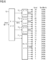
- Such a basic filter bank concept comprises an input-side filter bank 10 and a plurality of output-side filter banks 11 1 to 11 m and 12 1 to 12 n .
- the sampling rate at the input of the filter bank 10 is f A, Ein .
- the basic filter bank concept is only designed in two stages in this example.
- the filter banks 11 1 to 11 m and 12 1 to 12 n which respectively represent conventional complex-modulated filter banks.
- the filter banks 11 1 to 11 m have a useful channel number K Aus, 1
- the filter banks 12 1 to 12 n have the channel number K Aus, 2 .
- the actual number of channels equal to the product U A ⁇ K off, 1.2, where U A represents the oversampling factor of the input side filter bank.
- the output-side filter banks are therefore composed in the selected example only of two different filter bank types.
- the filter bank type with the channel number K Aus, 1 S 1 -fold and that with the channel number K Aus, 2 S 2 -fold are represented.
- the sampling rate at the output of the input-side filter bank 10 is f A, Zw and the sampling rates at the outputs of the output side filter banks 11 1 to 11 m and 12 1 to 12 n are f A, TB1 and f A, TB2 .
- the output-side channels are partially formed by the input-side filter bank 10.
- the output side filter banks 12 1 to 12 n in FIG Fig. 2 dashed lines can be omitted.
- the aim now is to clarify the structure of the filter bank system of FIG. 2 especially with regard to use in hearing aids to optimize.
- the lowest possible group delay in the individual channels and a total of the lowest possible energy consumption, ie as few filter operations are achieved. It has been found that in order to optimize the complete parameter space of the filter bank system in substantially two parameters can be reduced, namely, the input channel number K A and the oversampling factor U A of the input side filter bank 10th
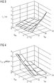
- the group delay time of a critical band of low frequencies as a function of the two parameters K and A is investigated U A.
- filters according to the Remez standard design linear-phase FIR filters
- the three-dimensional graphic of FIG. 3 is the group delay ⁇ g on the parameters U A and K A again. It shows a significant increase in group delay for the frequency group of the low frequencies in the right corner, ie at high input channel count K A and low oversampling factors U A. Differential group delays are thus more in the front and rear portions of the graphic, very small durations in the left corner of the graph, that is, at high oversampling factors U A and low input channel numbers K A. For higher frequencies, the group delay varies only slightly as a function of A U A and K.
- FIG. 4 the operation rate f OP, mult (for multiplications) of the entire filter bank as a function of K and U A A determined.
- the multiplication operation rate can here be regarded as representative of the total operating rate of the filter bank.
- FIG. 4 showing that the operation rate f OP, mult, in the left corner, that is at a high oversampling factor U A and a minor channel number K A, is relatively large.
- the so-called data rate "f data " can additionally be used. It results from all sampling rates cumulated over all subbands. As FIG. 5 shows, however, it is for a "full tree” of the filter system (see. FIG. 2 ) constant. Only for a "reduced tree” results in a function of the parameters U and A K A. In the example chosen, the output-side filter banks 12 1 to 12 n have been dispensed with. Thereby, a function of the data rate f data on the two parameters K and U A A resulted.
- a compromise can be found that takes into account all the optimization criteria (low group delay, low operation rate and possibly low data rate).
- the optimal structure leads to a full tree with four output-side filter banks 11 1 , 12 1 , 12 2 and 12 third
- polyphase filter banks can according to the invention for each partial filter bank in each case the cheapest Solution for realizing the frequency shift are selected:
- the prototype filter In the first case, the input signal of the respective sub-filter bank itself frequency offset, the prototype filter continues to have real coefficients, but is fed with a complex signal (implementation as a DFT filter bank). The output signal must be frequency shifted again in the opposite direction.
- the prototype filter In the second case, the prototype filter itself is complex modulated, which has this complex coefficient but is fed with a real signal.
- the zero phase of the frequency offset causing carrier oscillation is suitably chosen.
- the choice of both options is as follows: If the input signal of the respective sub-filter bank is real, then the second option is selected, it is complex, so the first one. In any case, only half-complex multiplications result for GDFT sub-filter banks in the prototype filters to be realized. In the case of a multi-stage filter bank, the frequency shifts required in the first case may be combined in front of and behind the DFT filter bank. Further improvements in computational complexity (energy consumption) and group delay can be achieved by substituting NPR ("non-perfect reconstructing filter banks”) filter banks instead of conventional PR (“perfectly reconstructed filter banks”) filter banks. Namely, the NPR filter banks may be designed to be sufficient for intensive subband processing.
- a filter bank composed of at least two cascaded stages or as a partial at least two-stage (analysis) filter bank, it can be used to split the input signal into K subband signals at a reduced sampling rate.
- a digital synthesis filter bank (SFB) for resynthesis after the manipulation of the subband signals may be constructed symmetrically to the analysis filter bank (AFB).
- the filter bank system described above can be used, for example, in a hearing device or another hearing device.
Description
Die vorliegende Erfindung betrifft ein Verfahren zum Optimieren einer Struktur einer mehrstufigen Filterbank, die eine eingangsseitige und eine ausgangsseitige Filterbank auf der Basis eines vorgegebenen Filtertyps aufweist, wobei die eingangsseitige Filterbank als variierbaren ersten Parameter die Eingangskanalzahl und als variierbaren zweiten Parameter einen Überabtastfaktor besitzt. Darüber hinaus betrifft die vorliegende Erfindung eine mehrstufige Filterbank, deren Struktur mit Hilfe eines obigen Verfahrens gewonnen ist. Ferner betrifft die vorliegende Erfindung auch eine Hörvorrichtung mit einer derartigen mehrstufigen Filterbank. Unter dem Begriff "Hörvorrichtung" wird hier jedes im oder am Ohr tragbare, schallausgebende Gerät, insbesondere ein Hörgerät, ein Headset, Kopfhörer und dergleichen, verstanden.The present invention relates to a method for optimizing a structure of a multi-stage filter bank having an input side and an output side filter bank based on a given filter type, wherein the input side filter bank has the input channel number as the variable first parameter and an oversampling factor as the variable second parameter. Moreover, the present invention relates to a multi-stage filter bank, the structure of which is obtained by means of a method above. Furthermore, the present invention also relates to a hearing device with such a multi-stage filter bank. The term "hearing device" is understood here to mean any sound-emitting device which can be worn in or on the ear, in particular a hearing device, a headset, headphones and the like.
Hörgeräte sind tragbare Hörvorrichtungen, die zur Versorgung von Schwerhörenden dienen. Um den zahlreichen individuellen Bedürfnissen entgegenzukommen, werden unterschiedliche Bauformen von Hörgeräten wie Hinter-dem-Ohr-Hörgeräte (HdO), Hörgerät mit externem Hörer (RIC: receiver in the canal) und In-dem-Ohr-Hörgeräte (IdO), z.B. auch Concha-Hörgeräte oder Kanal-Hörgeräte (ITE, CIC), bereitgestellt. Die beispielhaft aufgeführten Hörgeräte werden am Außenohr oder im Gehörgang getragen. Darüber hinaus stehen auf dem Markt aber auch Knochenleitungshörhilfen, implantierbare oder vibrotaktile Hörhilfen zur Verfügung. Dabei erfolgt die Stimulation des geschädigten Gehörs entweder mechanisch oder elektrisch.Hearing aids are portable hearing aids that are used to care for the hearing impaired. In order to meet the numerous individual needs, different types of hearing aids such as behind-the-ear hearing aids (BTE), hearing aid with external receiver (RIC: receiver in the canal) and in-the-ear hearing aids (IDO), e.g. Concha hearing aids or canal hearing aids (ITE, CIC). The hearing aids listed by way of example are worn on the outer ear or in the ear canal. In addition, bone conduction hearing aids, implantable or vibrotactile hearing aids are also available on the market. The stimulation of the damaged hearing takes place either mechanically or electrically.
Hörgeräte besitzen prinzipiell als wesentliche Komponenten einen Eingangswandler, einen Verstärker und einen Ausgangswandler. Der Eingangswandler ist in der Regel ein Schallempfänger, z. B. ein Mikrofon, und/oder ein elektromagnetischer Empfänger, z. B. eine Induktionsspule. Der Ausgangswandler ist meist als elektroakustischer Wandler, z. B. Miniaturlautsprecher, oder als elektromechanischer Wandler, z. B. Knochenleitungshörer, realisiert. Der Verstärker ist üblicherweise in eine Signalverarbeitungseinheit integriert. Dieser prinzipielle Aufbau ist in
Schallsignale, die von einem oder mehreren Mikrophonen eines Hörgeräts aufgenommen werden, werden üblicherweise zur weiteren Verarbeitung in Teilbandsignale zerlegt. Hierzu bedient man sich meist einer oder mehrerer frequenzselektiver digitaler Analyse-Filterbänke (AFB), wodurch K>1 Teilbandsignale erhalten werden. Nach der Zerlegung können teilbandspezifische Signalmanipulationen durchgeführt werden. Eine anschließende Resynthese der manipulierten Teilbandsignale kann mittels einer digitalen Synthese-Filterbank (SFB) erfolgen.Sound signals recorded by one or more microphones of a hearing aid are usually decomposed into subband signals for further processing. For this purpose, one usually uses one or more frequency-selective digital analysis filter banks (AFB), whereby K> 1 subband signals are obtained. Subsequent to the decomposition, subband specific signal manipulations can be performed. A subsequent resynthesis of the manipulated subband signals can be carried out by means of a digital synthesis filter bank (SFB).
An hochwertige Filterbänke in Hörgeräten werden gewisse Anforderungen gestellt. So wird beispielsweise in den untersten Bändern eine Kanalbandbreite von etwa 250 Hz benötigt. Ansonsten sollte sich der Bandabstand in etwa nach der Bark-Skala richten. Ferner ist eine Kanalzahl von mindestens 22 wünschenswert. Störanteile durch Aliasing sollen sicher unterhalb von 60dB liegen. Aufgrund der intensiven Teilbandverarbeitung (insbesondere die hohe erforderliche Verstärkung zur Kompensation des Hörschadens) bei Hörgeräten sind herkömmliche Verfahren zur Auslöschung von Aliasing nicht wirksam. Die Filterbänke sind daher grundsätzlich "nicht kritisch" abzutasten. Des Weiteren sollte die Gruppenlaufzeit (jeweils für AFB und SFB) deutlich unter 5 ms liegen und die Gruppenlaufzeitverzerrungen einen gewissen Rahmen nicht überschreiten. Insbesondere für hohe Frequenzen ist dabei die Gruppenlaufzeit so gering wie möglich zu halten, was einen wesentlichen limitierenden Faktor für die Filterbank darstellt.High-quality filter banks in hearing aids are subject to certain requirements. For example, in the bottommost bands, a channel bandwidth of about 250 Hz is needed. Otherwise, the band gap should be based on the Bark scale. Furthermore, a channel number of at least 22 is desirable. Disturbance due to aliasing should be below 60dB. Due to the intensive subband processing (in particular the high required amplification to compensate for the hearing damage) in hearing aids are conventional Method for extinguishing aliasing not effective. The filter banks are therefore fundamentally "non-critical" to scan. Furthermore, the group delay (in each case for AFB and SFB) should be well below 5 ms and the group delay distortions should not exceed a certain range. Especially for high frequencies, the group delay is to be kept as low as possible, which represents a significant limiting factor for the filter bank.
Bislang werden bereits Filterbänke mit mehrstufiger Baumstruktur und ungleichförmiger Aufteilung (Bark-Skala), jedoch ohne optimierter Sperrbereichsdämpfung und damit fehlender oder unzureichender Abwärtstastung eingesetzt (Lösung A). Darüber hinaus ist auch bekannt, eine einstufige (bspw. komplex modulierte) Filterbank einzusetzen (Lösung B). Schließlich werden für die Zerlegung der Schallsignale auch mehrstufige Filterbänke eingesetzt (Lösung C). Eine derartige Filterbank ist beispielsweise mit K Kanälen mit mindestens zwei unterschiedlichen Bandbreiten ausgestattet, wobei sich die Bandbreiten an den Randbedingungen der Bark-Skala orientieren, Kanalgruppen jedoch identische Bandbreite besitzen. Dadurch ergeben sich Vorteile gegenüber den Lösungen A und B.So far, filter banks with multi-level tree structure and non-uniform distribution (Bark scale), but without optimized stopband attenuation and thus missing or insufficient downward scanning are used (solution A). In addition, it is also known to use a single-stage (for example, complex-modulated) filter bank (solution B). Finally, multilevel filter banks are used for the decomposition of the sound signals (solution C). Such a filter bank is equipped, for example, with K channels with at least two different bandwidths, the bandwidths being based on the boundary conditions of the Bark scale, but channel groups having identical bandwidth. This results in advantages over solutions A and B.
Weiterhin ist durch die mehrstufige Filterbank eine erhöhte Anzahl von Teilbändern möglich, um eine verbesserte Auflösung gegenüber der Lösung A erreichen zu können. Gleichzeitig besteht jedoch kein Zwang zur Realisierung einer überhöhten Anzahl von Teilbändern, was als Verbesserung gegenüber der Lösung B anzusehen ist.Furthermore, an increased number of subbands is possible by the multi-stage filter bank in order to achieve an improved resolution compared to the solution A can. At the same time, however, there is no need to realize an excessive number of subbands, which is to be regarded as an improvement over the solution B.
Des Weiteren ist mit der mehrstufigen Filterbank eine Herabsetzung der Abtastrate der Teilbandsignale soweit möglich, wie es die Vermeidung von Störungen zulässt (Verbesserung gegenüber Lösung A). Die Herabsetzung der Abtastrate kann jedoch nur in dem Maße erfolgen, dass durch die Manipulation der Teilbandsignale keine Störungen durch spektrale Überfaltungen (Aliasing) entstehen. Dies führt zu einer Verbesserung gegenüber bekannten Filterbank-Verfahren zur Aliasing-Kompensation, wie sie beispielsweise beschrieben sind in
Aus dem Artikel von
Darüber hinaus beschreibt der Artikel
Ferner ist der Artikel
Die Aufgabe der vorliegenden Erfindung besteht darin, eine mehrstufige Filterbank bereitstellen zu können, die eine möglichst geringe Gruppenlaufzeit in den Teilbändern aufweist und mit möglichst wenig Energieaufwand betrieben werden kann.The object of the present invention is to be able to provide a multi-stage filter bank, which has the lowest possible group delay in the subbands and can be operated with the least possible expenditure of energy.
Erfindungsgemäß wird diese Aufgabe gelöst durch ein Verfahren zum Optimieren einer Struktur einer mehrstufigen Filterbank, die eine eingangsseitige und eine ausgangsseitige Filterbank mit Filtern eines vorgegebenen Filtertyps aufweist, wobei die eingangsseitige Filterbank als variierbaren ersten Parameter die Kanalzahl und als variierbaren zweiten Parameter einen Überabtastfaktor besitzt, umfassend die folgenden Schritte: Ermitteln jeweils einer Gruppenlaufzeit der mehrstufigen Filterbank für mehrere Wertepaare des ersten und zweiten Parameters, Ermitteln jeweils einer Operationsrate der mehrstufigen Filterbank für die mehrere Wertepaare des ersten und zweiten Parameters, Auswählen eines der mehreren Wertepaare, bei dem die zugehörige Gruppenlaufzeit und die zugehörige Operationsrate ein vorgegebenes Kriterium erfüllen, und Konfigurieren der eingangsseitigen Filterbank mit der Kanalzahl und dem Überabtastfaktor entsprechend dem ausgewählten Wertepaar.According to the invention, this object is achieved by a method for optimizing a structure of a multi-stage filter bank which has an input-side and an output-side filter bank with filters of a predetermined filter type, the input-side filter bank being a variable first parameter the channel number and as the variable second parameter has an oversampling factor, comprising the steps of: determining a group delay of the multi-stage filter bank for a plurality of pairs of values of the first and second parameters, respectively determining an operation rate of the multi-stage filter bank for the plurality of pairs of values of the first and second parameters, selecting one of the plurality of value pairs, where the associated group delay and the associated operation rate meet a predetermined criterion, and configuring the input side filter bank with the channel number and the oversampling factor corresponding to the selected value pair.
In vorteilhafter Weise ist es so möglich, ein Filterbanksystem, das zahlreiche Parameter besitzt, wie Nutzkanalzahl der eingangsseitigen Filterbank, Überabtastfaktor der eingangsseitigen Filterbank, Anzahl der ausgangsseitigen Filterbänke, Nutzkanalzahl der ausgangsseitigen Filterbänke, Überabtastfaktor der ausgangsseitigen Filterbänke, Baumstruktur "voller Baum" oder "reduzierter Baum" usw., nur anhand weniger, gezielt ausgewählter Parameter erfolgreich zu optimieren. Es ist also nicht ein aufwendiges Optimierungsverfahren in einem mehrdimensionalen Raum notwendig.Advantageously, it is possible, a filter bank system having numerous parameters, such as payload number of the input side filter bank, oversampling factor of the input side filter bank, number of output side filter banks, payload number of the output side filter banks, oversampling factor of the output side filter banks, tree structure "full tree" or "reduced Tree ", etc., can only be successfully optimized with the help of fewer, specifically selected parameters. So it is not a complex optimization process in a multi-dimensional space necessary.
Falls die mehrstufige Filterbank, d.h. das kaskadierte Filterbank-System, über die gesamte Bankbreite verschiedenstufig ist, kann für die mehreren Wertepaare jeweils zusätzlich eine Datenrate, die eine Abtastrate kumuliert über alle Teilbänder der mehrstufigen Filterbank darstellt, ermittelt und diese Datenrate für das Auswählen eines der mehreren Wertepaare herangezogen werden. Damit ergibt sich ein zusätzliches Auswertekriterium, mit dem der Ergebnisraum zielsicher eingeschränkt werden kann.If the multilevel filter bank, i. the cascaded filter bank system, over the entire bank width is different levels, for the several value pairs each additionally a data rate representing a sampling rate cumulative over all subbands of the multi-level filter bank determined, and this data rate are used for selecting one of the several value pairs. This results in an additional evaluation criterion, with which the result space can be confidently restricted.
In einer Weiterentwicklung kann anstatt von üblicherweise verwendeten "perfekt rekonstruierenden" Filterbänken (PR-Filterbank) eine "näherungsweise perfekt rekonstruierende" Filterbank (NPR-Filterbank) verwendet werden. Eine NPR-Filterbank ist für eine intensive Teilbandverarbeitung meist hinreichend. Mit einer NPR-Filterbank lassen sich weiter Aufwand und Gruppenlaufzeit einsparen.In a further development, an "approximately perfectly reconstructing" filter bank (NPR filter bank) can be used instead of the commonly used "perfectly reconstructed" filter banks (PR filter bank). An NPR filter bank is usually for intensive subband processing sufficient. With an NPR filter bank further effort and group delay can be saved.
Ferner kann es sich bei jeder Teil-Filterbank des FilterbankSystems um eine überabgetastete, komplex modulierte reguläre (DFT) oder frequenzverschobene (GDFT) Polyphasen-Filterbank handeln. Derartige Filterbänke besitzen weitreichende Variationsmöglichkeiten, sind aber mit dem erfindungsgemäßen Verfahren leicht zu optimieren.Further, each sub-filterbank of the filterbank system may be an oversampled complex-modulated regular (DFT) or frequency-shifted (GDFT) polyphase filter bank. Such filter banks have far-reaching possibilities of variation, but are easy to optimize with the method according to the invention.
Das vorgegebene Kriterium für die Optimierung kann darin bestehen, dass die Gruppenlaufzeit und die Operationsrate möglichst gering sind. Besitzen beide Parameter nicht bei ein und demselben Wertepaar ein Minimum, so ist ein geeigneter Kompromiss für die Parameterwerte und das dazugehörige Wertepaar (Eingangskanalzahl und Überabtastfaktor) zu wählen.The predefined criterion for the optimization can be that the group delay and the operation rate are as low as possible. If both parameters do not have a minimum for one and the same value pair, then a suitable compromise must be chosen for the parameter values and the corresponding value pair (input channel number and oversampling factor).
Vorteilhafterweise kann nun mit dem erfindungsgemäßen Verfahren eine mehrstufige Filterbank gefunden werden, deren Struktur hinsichtlich Gruppenlaufzeit und Energieverbrauch optimiert ist. Insbesondere eignet sich eine derartige mehrstufige Filterbank zur Eingangssignalverarbeitung in Hörvorrichtungen, speziell in Hörgeräten.Advantageously, a multi-stage filter bank can now be found with the method according to the invention, the structure of which is optimized in terms of group delay and energy consumption. In particular, such a multi-stage filter bank is suitable for input signal processing in hearing devices, especially in hearing aids.
Die vorliegende Erfindung wird nun anhand der beigefügten Zeichnungen näher erläutert, in denen zeigen:
- FIG 1
- den prinzipiellen Aufbau eines Hörgeräts gemäß dem Stand der Technik;
- FIG 2
- eine Baumstruktur eines zu optimierenden Basisfilterbankkonzepts;
- FIG 3
- ein Diagramm der Gruppenlaufzeit der Frequenzgruppe der niedrigen Frequenzen in Abhängigkeit von KEin und UEin;
- FIG 4
- ein Diagramm der Operationsrate für Multiplikationen der gesamten Filterbank in Abhängigkeit von KEin und UEin;
- FIG 5
- ein Diagramm der Datenrate aller Teilbänder (gesamte Samplezahl pro Zeiteinheit) in Abhängigkeit von KEin und UEin; und
- FIG 6
- eine Baumstruktur eines optimierten Filterbankkonzepts.
- FIG. 1
- the basic structure of a hearing aid according to the prior art;
- FIG. 2
- a tree structure of a basic filter bank concept to be optimized;
- FIG. 3
- a diagram of the group delay of the frequency group of low frequencies as a function of K and U A A;
- FIG. 4
- a diagram of the operation rate of multiplications of the entire filter bank as a function of K and U A A;
- FIG. 5
- a diagram of the data rate of all sub-bands (entire sample number per unit time) depending on K A and U A; and
- FIG. 6
- a tree structure of an optimized filter bank concept.
Die nachfolgend näher geschilderten Ausführungsformen stellen bevorzugte Ausführungsbeispiele der vorliegenden Erfindung dar. Für das erfindungsgemäße Optimierungsverfahren wird in dem folgenden Beispiel von einer Baumstruktur eines Filterbankkonzepts ausgegangen, wie es in
Das Basisfilterbankkonzept ist in diesem Beispiel lediglich zweistufig ausgelegt. Es verfügt also neben der eingangsseitigen Filterbank 10 in der ersten Stufe lediglich über eine zweite Stufe mit den Filterbänken 111 bis 11m und 121 bis 12n, welche jeweils herkömmliche komplex modulierte Filterbänke darstellen. Die Filterbänke 111 bis 11m besitzen eine Nutzkanalzahl KAus,1, während die Filterbänke 121 bis 12n die Kanalzahl KAus,2 besitzen. Die tatsächliche Kanalzahl entspricht dem Produkt UEin · KAus,1,2, wobei UEin den Überabtastfaktor der eingangsseitigen Filterbank repräsentiert.The basic filter bank concept is only designed in two stages in this example. Thus, besides the input-
Die ausgangsseitigen Filterbänke setzen sich in dem gewählten Beispiel also lediglich aus zwei verschiedenen Filterbanktypen zusammen. Dabei ist bei einem "vollen Baum" der Filterbanktyp mit der Kanalzahl KAus,1 S1-fach und derjenige mit der Kanalzahl KAus,2 S2-fach vertreten. Die Abtastrate am Ausgang der eingangsseitigen Filterbank 10 beträgt fA, Zw und die Abtastraten an den Ausgängen der ausgangsseitigen Filterbänke 111 bis 11m und 121 bis 12n betragen fA, TB1 bzw. fA, TB2.The output-side filter banks are therefore composed in the selected example only of two different filter bank types. In the case of a "full tree", the filter bank type with the channel number K Aus, 1 S 1 -fold and that with the channel number K Aus, 2 S 2 -fold are represented. The sampling rate at the output of the input-
Liegt lediglich ein "reduzierter Baum" vor, so werden die ausgangsseitigen Kanäle teilweise durch die eingangsseitige Filterbank 10 gebildet. Demnach kann beispielsweise auf die ausgangsseitigen Filterbänke 121 bis 12n (in
Ziel ist es nun, die Struktur des Filterbanksystems von
Zunächst wird die Gruppenlaufzeit einer Frequenzgruppe der niedrigen Frequenzen in Abhängigkeit der beiden Parameter KEin und UEin untersucht. Für die Untersuchung, wie auch für alle folgenden Untersuchungen werden Filter gemäß dem Remez-Standardentwurf (linearphasige FIR-Filter) verwendet. Die dreidimensionale Graphik von
Hohe Überabtastfaktoren UEin führen jedoch zu einer hohen Anzahl an notwendigen Operationen, wodurch der Energieverbrauch steigt. Demzufolge ist ein Kompromiss zwischen Gruppenlaufzeit und Anzahl der Operationen bzw. Operationsrate zu finden. Daher wurde entsprechend
Als zusätzliches Entscheidungskriterium für das Finden eines optimalen Wertepaares UEin/KEin kann zusätzlich die sogenannte Datenrate "fDaten" herangezogen werden. Sie ergibt sich aus allen Abtastraten kumuliert über alle Teilbänder. Wie
Insgesamt ist ein Kompromiss zu finden, der sämtlichen Optimierungskriterien (geringe Gruppenlaufzeit, geringe Operationsrate und ggf. geringe Datenrate) Rechnung trägt. In dem vorliegenden Beispiel stellte sich heraus, dass eine Filterbank mit der Baumstruktur gemäß
Für den Fall einer Einsetzung von frequenzverschobenen komplex modulierten (GDFT) Polyphasen-Filterbänken kann erfindungsgemäß für jede Teil-Filterbank jeweils die günstigste Lösung zur Realisierung der Frequenzverschiebung ausgewählt werden: In ersten Fall wird das Eingangssignal der jeweiligen Teilfilterbank selbst frequenzversetzt, wobei das Prototypfilter weiterhin reelle Koeffizienten aufweist, aber mit einem komplexen Signal gespeist wird (Realisierung als DFT-Filterbank). Das Ausgangssignal muss dabei wieder in die Gegenrichtung frequenzverschoben werden. Im zweiten Fall wird das Prototypfilter selbst komplex moduliert, wodurch dieses komplexe Koeffizienten aufweist, aber mit einem reellen Signal gespeist wird. Um die evtl. vorliegende Symmetrie von FIR Filterkoeffizienten zu bewahren, wird die Nullphase der den Frequenzversatz bewirkenden Trägerschwingung geeignet gewählt.
Die Auswahl aus beiden Möglichkeiten geschieht wie folgt: Ist das Eingangssignal der jeweiligen Teilfilterbank reell, so wird die zweite Möglichkeit ausgewählt, ist es komplex, so die erste. In jedem Fall ergeben sich so auch für GDFT-Teilfilterbänke in den zu realisierenden Prototypfiltern nur halbkomplexe Multiplikationen. Bei einer mehrstufigen Filterbank können gegebenenfalls die im ersten Fall nötigen Frequenzverschiebungen vor und hinter der DFT-Filterbank zusammengefasst werden.
Eine weitere Verbesserung in Hinblick auf Rechenaufwand (Energieverbrauch) und Gruppenlaufzeit kann dadurch erreicht werden, dass anstelle herkömmlicher PR-Filterbänke ("perfekt rekonstruierender Filterbänke") NPR-Filterbänke ("nicht perfekt rekonstruierende Filterbänke") eingesetzt werden. Die NPR-Filterbänke können nämlich so gestaltet sein, dass sie für eine intensive Teilbandverarbeitung hinreichend sind.In the case of an implementation of frequency-shifted complex-modulated (GDFT) polyphase filter banks can according to the invention for each partial filter bank in each case the cheapest Solution for realizing the frequency shift are selected: In the first case, the input signal of the respective sub-filter bank itself frequency offset, the prototype filter continues to have real coefficients, but is fed with a complex signal (implementation as a DFT filter bank). The output signal must be frequency shifted again in the opposite direction. In the second case, the prototype filter itself is complex modulated, which has this complex coefficient but is fed with a real signal. In order to preserve the possibly present symmetry of FIR filter coefficients, the zero phase of the frequency offset causing carrier oscillation is suitably chosen.
The choice of both options is as follows: If the input signal of the respective sub-filter bank is real, then the second option is selected, it is complex, so the first one. In any case, only half-complex multiplications result for GDFT sub-filter banks in the prototype filters to be realized. In the case of a multi-stage filter bank, the frequency shifts required in the first case may be combined in front of and behind the DFT filter bank.
Further improvements in computational complexity (energy consumption) and group delay can be achieved by substituting NPR ("non-perfect reconstructing filter banks") filter banks instead of conventional PR ("perfectly reconstructed filter banks") filter banks. Namely, the NPR filter banks may be designed to be sufficient for intensive subband processing.
Als eine aus mindestens zwei kaskadierten Stufen zusammengesetzte Filterbank bzw. als partiell mindestens zweistufige (Analyse-)Filterbank kann sie zur Zerlegung des Eingangssignals in K Teilbandsignale mit verminderter Abtastrate dienen. Eine digitale Synthesefilterbank (SFB) zur Resynthese nach der Manipulation der Teilbandsignale kann symmetrisch zu der Analyse-Filterbank (AFB) aufgebaut sein.As a filter bank composed of at least two cascaded stages or as a partial at least two-stage (analysis) filter bank, it can be used to split the input signal into K subband signals at a reduced sampling rate. A digital synthesis filter bank (SFB) for resynthesis after the manipulation of the subband signals may be constructed symmetrically to the analysis filter bank (AFB).
Insgesamt lässt sich mit der optimierten Filterbankstruktur eine kleinere Gruppenlaufzeit insbesondere bei den breitbandigeren, bei höheren Mittenfrequenzen zentrierten Kanälen erreichen, was eine Verbesserung gegenüber der einleitend geschilderten Lösung B darstellt. Als weiterer Vorteil des optimierten Filterbanksystems lässt sich der verminderte Rechenaufwand in der Analyse-Synthese-Filterbankkaskade nennen, was insbesondere eine Verbesserung gegenüber einer nicht optimierten Lösung C darstellt. Schließlich ergibt sich in vorteilhafter Weise auch ein stark verminderter Rechenaufwand in der Teilbandsignalverarbeitung durch Abwärtstastung der Teilbandsignale und Vermeidung einer überhöhten Kanalanzahl.Overall, a smaller group delay can be achieved with the optimized filter bank structure, in particular in the broadband channels centered at higher center frequencies, which represents an improvement over the solution B described in the introduction. Another advantage of the optimized filter bank system is the reduced computation effort in the analysis-synthesis filter bank cascade, which represents an improvement over a non-optimized solution C. Finally, there is advantageously also a greatly reduced computational effort in the subband signal processing by downward scanning of the subband signals and avoidance of an excessive number of channels.
Das oben beschriebene Filterbanksystem lässt sich beispielsweise in einem Hörgerät oder einer anderen Hörvorrichtung einsetzen.The filter bank system described above can be used, for example, in a hearing device or another hearing device.
Claims (5)
- A method for optimizing a structure of a multilevel filter bank which comprises an input-side filter bank (10) and an output-side filter bank (111, 11m,; 121, 12n) with filters of a defined filter type, with the input-side filter bank (10) having the channel number (KEin) as a variable first parameter, and an oversampling factor (UEin) as a variable second parameter,
characterized by- determining a group delay (τg) of the multilevel filter bank for each of a plurality of value pairs of the first and second parameters,- determining an operation rate (fOp,mult) of the multilevel filter bank for each of the plurality of value pairs of the first and second parameters,- selecting one of the plurality of value pairs for which the associated group delay (τg) and the associated operation rate (fOp,mult) satisfy a defined criterion, and- configuring the input-side filter bank (10) with the channel number and the oversampling factor corresponding to the selected value pair. - The method as claimed in claim 1, wherein levels of the multilevel filter bank differ across the full band width, a cumulative sampling rate across all subbands of the multilevel filter bank is additionally determined as the data rate for each of the plurality of value pairs, and the respective data rate is used to select one of the plurality of value pairs.
- The method as claimed in claim 1 or 2, wherein the input-side and output-side filter banks, with regard to a synthesis filter bank, are each an NPR filter bank.
- The method as claimed in one of the preceding claims, wherein the input-side and output-side filter banks are each an oversampled, complex modulated polyphase filter bank.
- The method as claimed in one of the preceding claims, wherein the defined criterion is to minimize the group delay (τg) and the operation rate (fOp,mult).
Applications Claiming Priority (1)
| Application Number | Priority Date | Filing Date | Title |
|---|---|---|---|
| DE102008024535A DE102008024535A1 (en) | 2008-05-21 | 2008-05-21 | Method for optimizing a multi-level filter bank and corresponding filter bank and hearing device |
Publications (3)
| Publication Number | Publication Date |
|---|---|
| EP2124335A2 EP2124335A2 (en) | 2009-11-25 |
| EP2124335A3 EP2124335A3 (en) | 2012-11-21 |
| EP2124335B1 true EP2124335B1 (en) | 2018-03-28 |
Family
ID=40996731
Family Applications (1)
| Application Number | Title | Priority Date | Filing Date |
|---|---|---|---|
| EP09159307.9A Active EP2124335B1 (en) | 2008-05-21 | 2009-05-04 | Method for optimising a multi-stage filter bank and corresponding filter bank and hearing aid |
Country Status (4)
| Country | Link |
|---|---|
| US (1) | US8150081B2 (en) |
| EP (1) | EP2124335B1 (en) |
| DE (1) | DE102008024535A1 (en) |
| DK (1) | DK2124335T3 (en) |
Cited By (1)
| Publication number | Priority date | Publication date | Assignee | Title |
|---|---|---|---|---|
| EP4093052A1 (en) | 2021-05-21 | 2022-11-23 | Sivantos Pte. Ltd. | Method and apparatus for frequency-selective processing of a low latency audio signal |
Families Citing this family (6)
| Publication number | Priority date | Publication date | Assignee | Title |
|---|---|---|---|---|
| DE102008024490B4 (en) * | 2008-05-21 | 2011-09-22 | Siemens Medical Instruments Pte. Ltd. | Filter bank system for hearing aids |
| DE102009036610B4 (en) * | 2009-07-09 | 2017-11-16 | Sivantos Pte. Ltd. | Filter bank arrangement for a hearing device |
| DE102010026884B4 (en) | 2010-07-12 | 2013-11-07 | Siemens Medical Instruments Pte. Ltd. | Method for operating a hearing device with two-stage transformation |
| DE102010041643B4 (en) | 2010-09-29 | 2014-01-30 | Siemens Medical Instruments Pte. Ltd. | Hearing aid for frequency compression |
| WO2013101136A1 (en) * | 2011-12-30 | 2013-07-04 | Intel Corporation | Dual composite field advanced encryption standard memory encryption engine |
| CN106160702A (en) * | 2016-07-08 | 2016-11-23 | 桂林电子科技大学 | The method for designing of approximation Perfect Reconstruction monoarch DFT modulated filter bank |
Family Cites Families (1)
| Publication number | Priority date | Publication date | Assignee | Title |
|---|---|---|---|---|
| AU7118696A (en) * | 1995-10-10 | 1997-04-30 | Audiologic, Inc. | Digital signal processing hearing aid with processing strategy selection |
-
2008
- 2008-05-21 DE DE102008024535A patent/DE102008024535A1/en not_active Withdrawn
-
2009
- 2009-05-04 EP EP09159307.9A patent/EP2124335B1/en active Active
- 2009-05-04 DK DK09159307.9T patent/DK2124335T3/en active
- 2009-05-20 US US12/469,030 patent/US8150081B2/en active Active
Non-Patent Citations (1)
| Title |
|---|
| None * |
Cited By (3)
| Publication number | Priority date | Publication date | Assignee | Title |
|---|---|---|---|---|
| EP4093052A1 (en) | 2021-05-21 | 2022-11-23 | Sivantos Pte. Ltd. | Method and apparatus for frequency-selective processing of a low latency audio signal |
| DE102021205251A1 (en) | 2021-05-21 | 2022-11-24 | Sivantos Pte. Ltd. | Method and device for frequency-selective processing of an audio signal with low latency |
| US11910162B2 (en) | 2021-05-21 | 2024-02-20 | Sivantos Pte. Ltd. | Method and device for frequency-selective processing of an audio signal with low latency |
Also Published As
| Publication number | Publication date |
|---|---|
| EP2124335A3 (en) | 2012-11-21 |
| US20090290737A1 (en) | 2009-11-26 |
| DE102008024535A1 (en) | 2009-12-03 |
| EP2124335A2 (en) | 2009-11-25 |
| DK2124335T3 (en) | 2018-07-16 |
| US8150081B2 (en) | 2012-04-03 |
Similar Documents
| Publication | Publication Date | Title |
|---|---|---|
| EP2124334B1 (en) | Filter bank system for hearing aids | |
| EP2124335B1 (en) | Method for optimising a multi-stage filter bank and corresponding filter bank and hearing aid | |
| DE69737235T2 (en) | DIGITAL HEARING DEVICE USING DIFFERENTIAL SIGNALING REPRESENTATIONS | |
| DE102010026884B4 (en) | Method for operating a hearing device with two-stage transformation | |
| EP2645743B1 (en) | Hearing aid for a binaural supply and method for providing a binaural supply | |
| EP2280482B1 (en) | Filter bank assembly for a hearing device | |
| DE102010041653A1 (en) | Method and apparatus for frequency compression with selective frequency shift | |
| DE102013207403B3 (en) | Method for controlling an adaptation step size and hearing device | |
| EP2124482B1 (en) | Hearing device with equalisation filter in a filterbank system | |
| DE102008017550A1 (en) | Multi-stage estimation method for noise reduction and hearing aid | |
| EP1983800B1 (en) | Hearing device with low-interference receiver control and corresponding method | |
| EP2629550B1 (en) | Hearing device with adaptive filter and method of filtering an audio signal | |
| EP1912470A2 (en) | Method for the dynamic compression of an audio signal and corresponding hearing device | |
| EP1945000B1 (en) | Method for reducing interference and corresponding acoustic system | |
| EP2190218B1 (en) | Filter bank system with specific stop-band attenuation for a hearing device | |
| EP2437521B1 (en) | Method for frequency compression with harmonic adjustment and corresponding device | |
| EP3852388A1 (en) | Method for tuning the respective phase difference of a first microphone and a second microphone | |
| EP2373065B1 (en) | Hearing aid and method for creating an omnidirectional alignment characteristic | |
| EP3048813B1 (en) | Method and device for suppressing noise based on inter-subband correlation | |
| EP2622879B1 (en) | Method and device for frequency compression | |
| DE102007010601A1 (en) | Hearing system with distributed signal processing and corresponding method | |
| EP2418876A1 (en) | Method for reducing interference and hearing aid |
Legal Events
| Date | Code | Title | Description |
|---|---|---|---|
| PUAI | Public reference made under article 153(3) epc to a published international application that has entered the european phase |
Free format text: ORIGINAL CODE: 0009012 |
|
| AK | Designated contracting states |
Kind code of ref document: A2 Designated state(s): AT BE BG CH CY CZ DE DK EE ES FI FR GB GR HR HU IE IS IT LI LT LU LV MC MK MT NL NO PL PT RO SE SI SK TR |
|
| PUAL | Search report despatched |
Free format text: ORIGINAL CODE: 0009013 |
|
| AK | Designated contracting states |
Kind code of ref document: A3 Designated state(s): AT BE BG CH CY CZ DE DK EE ES FI FR GB GR HR HU IE IS IT LI LT LU LV MC MK MT NL NO PL PT RO SE SI SK TR |
|
| AX | Request for extension of the european patent |
Extension state: AL BA RS |
|
| RIC1 | Information provided on ipc code assigned before grant |
Ipc: H03H 17/02 20060101AFI20121016BHEP |
|
| 17P | Request for examination filed |
Effective date: 20130521 |
|
| RAP1 | Party data changed (applicant data changed or rights of an application transferred) |
Owner name: SIVANTOS PTE. LTD. |
|
| GRAP | Despatch of communication of intention to grant a patent |
Free format text: ORIGINAL CODE: EPIDOSNIGR1 |
|
| STAA | Information on the status of an ep patent application or granted ep patent |
Free format text: STATUS: GRANT OF PATENT IS INTENDED |
|
| INTG | Intention to grant announced |
Effective date: 20171030 |
|
| GRAS | Grant fee paid |
Free format text: ORIGINAL CODE: EPIDOSNIGR3 |
|
| RAP1 | Party data changed (applicant data changed or rights of an application transferred) |
Owner name: SIVANTOS PTE. LTD. |
|
| GRAA | (expected) grant |
Free format text: ORIGINAL CODE: 0009210 |
|
| STAA | Information on the status of an ep patent application or granted ep patent |
Free format text: STATUS: THE PATENT HAS BEEN GRANTED |
|
| AK | Designated contracting states |
Kind code of ref document: B1 Designated state(s): AT BE BG CH CY CZ DE DK EE ES FI FR GB GR HR HU IE IS IT LI LT LU LV MC MK MT NL NO PL PT RO SE SI SK TR |
|
| REG | Reference to a national code |
Ref country code: GB Ref legal event code: FG4D Free format text: NOT ENGLISH |
|
| REG | Reference to a national code |
Ref country code: CH Ref legal event code: EP |
|
| REG | Reference to a national code |
Ref country code: AT Ref legal event code: REF Ref document number: 984277 Country of ref document: AT Kind code of ref document: T Effective date: 20180415 |
|
| REG | Reference to a national code |
Ref country code: IE Ref legal event code: FG4D Free format text: LANGUAGE OF EP DOCUMENT: GERMAN |
|
| REG | Reference to a national code |
Ref country code: DE Ref legal event code: R096 Ref document number: 502009014849 Country of ref document: DE |
|
| REG | Reference to a national code |
Ref country code: CH Ref legal event code: NV Representative=s name: E. BLUM AND CO. AG PATENT- UND MARKENANWAELTE , CH |
|
| REG | Reference to a national code |
Ref country code: FR Ref legal event code: PLFP Year of fee payment: 10 |
|
| REG | Reference to a national code |
Ref country code: DK Ref legal event code: T3 Effective date: 20180711 |
|
| PG25 | Lapsed in a contracting state [announced via postgrant information from national office to epo] |
Ref country code: NO Free format text: LAPSE BECAUSE OF FAILURE TO SUBMIT A TRANSLATION OF THE DESCRIPTION OR TO PAY THE FEE WITHIN THE PRESCRIBED TIME-LIMIT Effective date: 20180628 Ref country code: FI Free format text: LAPSE BECAUSE OF FAILURE TO SUBMIT A TRANSLATION OF THE DESCRIPTION OR TO PAY THE FEE WITHIN THE PRESCRIBED TIME-LIMIT Effective date: 20180328 Ref country code: LT Free format text: LAPSE BECAUSE OF FAILURE TO SUBMIT A TRANSLATION OF THE DESCRIPTION OR TO PAY THE FEE WITHIN THE PRESCRIBED TIME-LIMIT Effective date: 20180328 Ref country code: HR Free format text: LAPSE BECAUSE OF FAILURE TO SUBMIT A TRANSLATION OF THE DESCRIPTION OR TO PAY THE FEE WITHIN THE PRESCRIBED TIME-LIMIT Effective date: 20180328 |
|
| REG | Reference to a national code |
Ref country code: NL Ref legal event code: MP Effective date: 20180328 |
|
| REG | Reference to a national code |
Ref country code: LT Ref legal event code: MG4D |
|
| PG25 | Lapsed in a contracting state [announced via postgrant information from national office to epo] |
Ref country code: GR Free format text: LAPSE BECAUSE OF FAILURE TO SUBMIT A TRANSLATION OF THE DESCRIPTION OR TO PAY THE FEE WITHIN THE PRESCRIBED TIME-LIMIT Effective date: 20180629 Ref country code: BG Free format text: LAPSE BECAUSE OF FAILURE TO SUBMIT A TRANSLATION OF THE DESCRIPTION OR TO PAY THE FEE WITHIN THE PRESCRIBED TIME-LIMIT Effective date: 20180628 Ref country code: SE Free format text: LAPSE BECAUSE OF FAILURE TO SUBMIT A TRANSLATION OF THE DESCRIPTION OR TO PAY THE FEE WITHIN THE PRESCRIBED TIME-LIMIT Effective date: 20180328 Ref country code: LV Free format text: LAPSE BECAUSE OF FAILURE TO SUBMIT A TRANSLATION OF THE DESCRIPTION OR TO PAY THE FEE WITHIN THE PRESCRIBED TIME-LIMIT Effective date: 20180328 |
|
| PG25 | Lapsed in a contracting state [announced via postgrant information from national office to epo] |
Ref country code: MT Free format text: LAPSE BECAUSE OF FAILURE TO SUBMIT A TRANSLATION OF THE DESCRIPTION OR TO PAY THE FEE WITHIN THE PRESCRIBED TIME-LIMIT Effective date: 20180328 |
|
| PG25 | Lapsed in a contracting state [announced via postgrant information from national office to epo] |
Ref country code: NL Free format text: LAPSE BECAUSE OF FAILURE TO SUBMIT A TRANSLATION OF THE DESCRIPTION OR TO PAY THE FEE WITHIN THE PRESCRIBED TIME-LIMIT Effective date: 20180328 Ref country code: PL Free format text: LAPSE BECAUSE OF FAILURE TO SUBMIT A TRANSLATION OF THE DESCRIPTION OR TO PAY THE FEE WITHIN THE PRESCRIBED TIME-LIMIT Effective date: 20180328 Ref country code: ES Free format text: LAPSE BECAUSE OF FAILURE TO SUBMIT A TRANSLATION OF THE DESCRIPTION OR TO PAY THE FEE WITHIN THE PRESCRIBED TIME-LIMIT Effective date: 20180328 Ref country code: EE Free format text: LAPSE BECAUSE OF FAILURE TO SUBMIT A TRANSLATION OF THE DESCRIPTION OR TO PAY THE FEE WITHIN THE PRESCRIBED TIME-LIMIT Effective date: 20180328 Ref country code: RO Free format text: LAPSE BECAUSE OF FAILURE TO SUBMIT A TRANSLATION OF THE DESCRIPTION OR TO PAY THE FEE WITHIN THE PRESCRIBED TIME-LIMIT Effective date: 20180328 Ref country code: IT Free format text: LAPSE BECAUSE OF FAILURE TO SUBMIT A TRANSLATION OF THE DESCRIPTION OR TO PAY THE FEE WITHIN THE PRESCRIBED TIME-LIMIT Effective date: 20180328 |
|
| PG25 | Lapsed in a contracting state [announced via postgrant information from national office to epo] |
Ref country code: CZ Free format text: LAPSE BECAUSE OF FAILURE TO SUBMIT A TRANSLATION OF THE DESCRIPTION OR TO PAY THE FEE WITHIN THE PRESCRIBED TIME-LIMIT Effective date: 20180328 Ref country code: SK Free format text: LAPSE BECAUSE OF FAILURE TO SUBMIT A TRANSLATION OF THE DESCRIPTION OR TO PAY THE FEE WITHIN THE PRESCRIBED TIME-LIMIT Effective date: 20180328 |
|
| PG25 | Lapsed in a contracting state [announced via postgrant information from national office to epo] |
Ref country code: PT Free format text: LAPSE BECAUSE OF FAILURE TO SUBMIT A TRANSLATION OF THE DESCRIPTION OR TO PAY THE FEE WITHIN THE PRESCRIBED TIME-LIMIT Effective date: 20180730 |
|
| REG | Reference to a national code |
Ref country code: DE Ref legal event code: R097 Ref document number: 502009014849 Country of ref document: DE |
|
| REG | Reference to a national code |
Ref country code: BE Ref legal event code: MM Effective date: 20180531 |
|
| PG25 | Lapsed in a contracting state [announced via postgrant information from national office to epo] |
Ref country code: MC Free format text: LAPSE BECAUSE OF FAILURE TO SUBMIT A TRANSLATION OF THE DESCRIPTION OR TO PAY THE FEE WITHIN THE PRESCRIBED TIME-LIMIT Effective date: 20180328 |
|
| PLBE | No opposition filed within time limit |
Free format text: ORIGINAL CODE: 0009261 |
|
| STAA | Information on the status of an ep patent application or granted ep patent |
Free format text: STATUS: NO OPPOSITION FILED WITHIN TIME LIMIT |
|
| REG | Reference to a national code |
Ref country code: IE Ref legal event code: MM4A |
|
| 26N | No opposition filed |
Effective date: 20190103 |
|
| PG25 | Lapsed in a contracting state [announced via postgrant information from national office to epo] |
Ref country code: LU Free format text: LAPSE BECAUSE OF NON-PAYMENT OF DUE FEES Effective date: 20180504 |
|
| PG25 | Lapsed in a contracting state [announced via postgrant information from national office to epo] |
Ref country code: IE Free format text: LAPSE BECAUSE OF NON-PAYMENT OF DUE FEES Effective date: 20180504 |
|
| PG25 | Lapsed in a contracting state [announced via postgrant information from national office to epo] |
Ref country code: SI Free format text: LAPSE BECAUSE OF FAILURE TO SUBMIT A TRANSLATION OF THE DESCRIPTION OR TO PAY THE FEE WITHIN THE PRESCRIBED TIME-LIMIT Effective date: 20180328 Ref country code: BE Free format text: LAPSE BECAUSE OF NON-PAYMENT OF DUE FEES Effective date: 20180531 |
|
| REG | Reference to a national code |
Ref country code: AT Ref legal event code: MM01 Ref document number: 984277 Country of ref document: AT Kind code of ref document: T Effective date: 20180504 |
|
| PG25 | Lapsed in a contracting state [announced via postgrant information from national office to epo] |
Ref country code: AT Free format text: LAPSE BECAUSE OF NON-PAYMENT OF DUE FEES Effective date: 20180504 |
|
| PG25 | Lapsed in a contracting state [announced via postgrant information from national office to epo] |
Ref country code: TR Free format text: LAPSE BECAUSE OF FAILURE TO SUBMIT A TRANSLATION OF THE DESCRIPTION OR TO PAY THE FEE WITHIN THE PRESCRIBED TIME-LIMIT Effective date: 20180328 |
|
| PG25 | Lapsed in a contracting state [announced via postgrant information from national office to epo] |
Ref country code: HU Free format text: LAPSE BECAUSE OF FAILURE TO SUBMIT A TRANSLATION OF THE DESCRIPTION OR TO PAY THE FEE WITHIN THE PRESCRIBED TIME-LIMIT; INVALID AB INITIO Effective date: 20090504 |
|
| PG25 | Lapsed in a contracting state [announced via postgrant information from national office to epo] |
Ref country code: CY Free format text: LAPSE BECAUSE OF FAILURE TO SUBMIT A TRANSLATION OF THE DESCRIPTION OR TO PAY THE FEE WITHIN THE PRESCRIBED TIME-LIMIT Effective date: 20180328 Ref country code: MK Free format text: LAPSE BECAUSE OF NON-PAYMENT OF DUE FEES Effective date: 20180328 |
|
| PG25 | Lapsed in a contracting state [announced via postgrant information from national office to epo] |
Ref country code: IS Free format text: LAPSE BECAUSE OF FAILURE TO SUBMIT A TRANSLATION OF THE DESCRIPTION OR TO PAY THE FEE WITHIN THE PRESCRIBED TIME-LIMIT Effective date: 20180728 |
|
| PGFP | Annual fee paid to national office [announced via postgrant information from national office to epo] |
Ref country code: FR Payment date: 20230517 Year of fee payment: 15 Ref country code: DK Payment date: 20230522 Year of fee payment: 15 Ref country code: DE Payment date: 20230519 Year of fee payment: 15 Ref country code: CH Payment date: 20230605 Year of fee payment: 15 |
|
| PGFP | Annual fee paid to national office [announced via postgrant information from national office to epo] |
Ref country code: GB Payment date: 20230522 Year of fee payment: 15 |