EP2123820A1 - Electronic safety system for an electric household appliance with an access door - Google Patents
Electronic safety system for an electric household appliance with an access door Download PDFInfo
- Publication number
- EP2123820A1 EP2123820A1 EP09006501A EP09006501A EP2123820A1 EP 2123820 A1 EP2123820 A1 EP 2123820A1 EP 09006501 A EP09006501 A EP 09006501A EP 09006501 A EP09006501 A EP 09006501A EP 2123820 A1 EP2123820 A1 EP 2123820A1
- Authority
- EP
- European Patent Office
- Prior art keywords
- door
- household appliance
- electric
- electric household
- blackout
- Prior art date
- Legal status (The legal status is an assumption and is not a legal conclusion. Google has not performed a legal analysis and makes no representation as to the accuracy of the status listed.)
- Granted
Links
- 238000001514 detection method Methods 0.000 claims abstract description 3
- 239000003990 capacitor Substances 0.000 claims description 67
- 238000005259 measurement Methods 0.000 claims description 7
- 241000282414 Homo sapiens Species 0.000 claims 1
- 238000000034 method Methods 0.000 description 5
- 230000005284 excitation Effects 0.000 description 4
- 238000005406 washing Methods 0.000 description 3
- 230000003213 activating effect Effects 0.000 description 1
- 230000003111 delayed effect Effects 0.000 description 1
- 238000010586 diagram Methods 0.000 description 1
- 238000007599 discharging Methods 0.000 description 1
- 238000001035 drying Methods 0.000 description 1
- 230000002045 lasting effect Effects 0.000 description 1
- 230000007257 malfunction Effects 0.000 description 1
Images




Classifications
-
- D—TEXTILES; PAPER
- D06—TREATMENT OF TEXTILES OR THE LIKE; LAUNDERING; FLEXIBLE MATERIALS NOT OTHERWISE PROVIDED FOR
- D06F—LAUNDERING, DRYING, IRONING, PRESSING OR FOLDING TEXTILE ARTICLES
- D06F37/00—Details specific to washing machines covered by groups D06F21/00 - D06F25/00
- D06F37/42—Safety arrangements, e.g. for stopping rotation of the receptacle upon opening of the casing door
-
- D—TEXTILES; PAPER
- D06—TREATMENT OF TEXTILES OR THE LIKE; LAUNDERING; FLEXIBLE MATERIALS NOT OTHERWISE PROVIDED FOR
- D06F—LAUNDERING, DRYING, IRONING, PRESSING OR FOLDING TEXTILE ARTICLES
- D06F2101/00—User input for the control of domestic laundry washing machines, washer-dryers or laundry dryers
-
- D—TEXTILES; PAPER
- D06—TREATMENT OF TEXTILES OR THE LIKE; LAUNDERING; FLEXIBLE MATERIALS NOT OTHERWISE PROVIDED FOR
- D06F—LAUNDERING, DRYING, IRONING, PRESSING OR FOLDING TEXTILE ARTICLES
- D06F2103/00—Parameters monitored or detected for the control of domestic laundry washing machines, washer-dryers or laundry dryers
-
- D—TEXTILES; PAPER
- D06—TREATMENT OF TEXTILES OR THE LIKE; LAUNDERING; FLEXIBLE MATERIALS NOT OTHERWISE PROVIDED FOR
- D06F—LAUNDERING, DRYING, IRONING, PRESSING OR FOLDING TEXTILE ARTICLES
- D06F2103/00—Parameters monitored or detected for the control of domestic laundry washing machines, washer-dryers or laundry dryers
- D06F2103/40—Opening or locking status of doors
-
- D—TEXTILES; PAPER
- D06—TREATMENT OF TEXTILES OR THE LIKE; LAUNDERING; FLEXIBLE MATERIALS NOT OTHERWISE PROVIDED FOR
- D06F—LAUNDERING, DRYING, IRONING, PRESSING OR FOLDING TEXTILE ARTICLES
- D06F2105/00—Systems or parameters controlled or affected by the control systems of washing machines, washer-dryers or laundry dryers
- D06F2105/62—Stopping or disabling machine operation
-
- D—TEXTILES; PAPER
- D06—TREATMENT OF TEXTILES OR THE LIKE; LAUNDERING; FLEXIBLE MATERIALS NOT OTHERWISE PROVIDED FOR
- D06F—LAUNDERING, DRYING, IRONING, PRESSING OR FOLDING TEXTILE ARTICLES
- D06F34/00—Details of control systems for washing machines, washer-dryers or laundry dryers
- D06F34/08—Control circuits or arrangements thereof
Definitions
- the present invention relates to an electronic safety system for an electric household appliance with an access door.
- the present invention relates to an electronic safety system for controlling restart of an electric household appliance, such as a washing machine and/or drier or any other similar household appliance, following a blackout, to which the following description refers purely by way of example.
- some known electric household appliances such as washing machines or driers, comprise a casing; a laundry drum housed inside the casing and communicating with the outside through a drum access opening in the casing; and a door for opening/closing the opening.
- Some of the above appliances are equipped with a safety system connecting the door mechanically to a safety switch along a main power circuit connected to the power line of the appliance.
- the safety switch When the door is opened, the safety switch is activated to cut off power and immediately stop the appliance; and, conversely, when the door is closed again, the safety switch in the main circuit is closed to power and restart the appliance.
- Safety systems of this sort have the major drawback of automatically restarting the appliance when the door is closed, by closing the safety switch and so powering the appliance.
- the safety switch in the main power circuit ensures the appliance is stopped immediately if the door is inadvertently opened during the wash cycle, it fails to address other hazard situations.
- the door may be opened, thus allowing a child to climb into the laundry drum.
- accidentally closing the door closes the safety switch, so the appliance can be restarted when power is restored. That is, when power is restored with the safety switch closed, the appliance is restarted automatically, with disastrous consequences for the child inside the drum.
- an electric household appliance as claimed in Claim 1 and preferably, though not necessarily, in any one of the Claims depending directly or indirectly on Claim 1.
- an electronic safety system installable in an electric household appliance as claimed in Claim 15.
- Number 1 in Figure 1 indicates as a whole an electric household appliance substantially comprising a casing 2; a laundry drum 3 mounted inside casing 2 to hold a given amount of laundry, and directly facing a laundry loading/unloading opening 4 formed in casing 2; and an access door 5 fitted to casing 2 to move, e.g. rotate, between an open position and a closed position opening and closing opening 4 respectively.
- Electric household appliance 1 may be a washing and/or drying machine or any similar appliance, and comprises an electronic safety system 6 for determining a hazard condition - corresponding to door 5 being opened when electric power supply to the appliance is cut off, i.e. during a power cut (blackout) - or a safety condition - corresponding to door 5 not being opened during the power cut.
- an electronic safety system 6 for determining a hazard condition - corresponding to door 5 being opened when electric power supply to the appliance is cut off, i.e. during a power cut (blackout) - or a safety condition - corresponding to door 5 not being opened during the power cut.
- Electronic safety system 6 is also designed to selectively disable or enable operation of appliance 1 upon detecting the hazard or safety condition respectively.
- the appliance comprises various internal electric equipment 7, such as an electric motor, pumps, and various known electric devices; and a main power circuit 8 connecting internal electric equipment 7 to a main power source 9 comprising, for example, an electric line at a predetermined supply voltage V1 of preferably, though not necessarily, about 230 V.
- V1 a predetermined supply voltage
- Main power circuit 8 comprises a power branch 10 connecting the external electric power source to electric equipment 7; an electronic switch 11 located along power branch 10, and which switches to off or on to respectively disconnect or connect appliance 1 to power source 9; and an electromechanical switch 14 located along power branch 10 and connected to door 5 to open and close when door 5 is moved into the open and closed position respectively.
- electronic switch 11 may preferably, though not necessarily, comprise a TRIAC which receives a control signal SCOM and, depending on control signal SCOM, switches to on or off to respectively enable or cut off electric power supply to electric equipment 7.
- TRIAC which receives a control signal SCOM and, depending on control signal SCOM, switches to on or off to respectively enable or cut off electric power supply to electric equipment 7.
- Electronic safety system 6 comprises a detecting module 12 for detecting the hazard or safety condition; and a control module 13 for selectively disabling or enabling electronic switch 11 on detecting the hazard or safety condition respectively.
- Detecting module 12 also comprises a mechanism 18, which cooperates with door 5 to move electric contact 16 mechanically from the work position to the rest position when door 5 is moved from the closed to the open position. More specifically, mechanism 18 is designed not to move electric contact 16 in any way when door 5 moves from the open to the closed position.
- Detecting module 12 also comprises an electromagnetic device 19 which, when excited, generates a magnetic field to move electric contact 16 from the rest position, i.e. opening, to the work position, i.e. closing electric detecting branch 15.
- electromagnetic device 19 may comprise a coil which receives an excitation signal SE to generate a magnetic field to move electric contact 16 from the rest to the work position.
- Control module 13 comprises a microprocessor having a first input connected to the second terminal of electric detecting branch 15 to receive status signal ST; a second input receiving a priority enabling signal SA; a first output supplying control signal SCOM to electronic switch 11; and a second output supplying excitation signal SE to electromagnetic device 19.
- control module 13 when signal ST indicates the hazard condition, control module 13 generates control signal SCOM which disables electronic switch 11; and, when signal ST indicates the safety condition, control module 13 generates control signal SCOM to enable electronic switch 11.
- Priority enabling signal SA may be generated by a control interface 21 on casing 2, to allow user consent to start appliance 1 after a power cut.
- control interface 21 comprises a button which is pressed by the user to supply priority enabling signal SA to the control module.
- control module 13 receiving status signal ST indicating the safety condition, therefore generates control signal SCOM to enable the TRIAC and so allow the appliance to continue the wash cycle interrupted by the power cut.
- mechanism 18 moves electric contact 16 from the work position to the rest position.
- electromagnetic device 19 receiving no excitation signal from the control module, generates no magnetic field, so electric contact 16 remains in the rest position. Closure of door 5 produces no movement of electric contact 16, which therefore remains in the rest position, thus generating a status signal ST indicating the hazard condition.
- control module 13 When power is restored, control module 13 acquires the hazard condition indicated in status signal ST, and generates control signal SCOM to keep electronic switch 11 disabled and so cut off power supply to electric equipment 7. In which case, control module 13 keeps the TRIAC and, hence, appliance 1 disabled, and remains on standby awaiting priority enabling signal SA from the user. The standby condition terminates when the user presses the button to generate priority enabling signal SA. More specifically, on receiving priority enabling signal SA, control module 13 enables the TRIAC to allow appliance 1 to start operating again, and at the same time supplies excitation signal SE to electromagnetic device 19 which moves electric contact 16 into the work position.
- the electronic safety system 6 is configured to: detecting the hazard condition corresponding to said access door being opened during a black out, or a safety condition corresponding to said access door not being opened during said black out; and selectively disabling or enabling said electronic switching means upon detection of said hazard condition or said safety condition respectively.
- electronic safety system 6 comprises detecting means 12 comprising an electric contact 16 movable between a work position and a rest position; mechanical means 18 which cooperate with the access door 5 to move the electric contact 16 from the work position to the rest position when the access door 5 is moved into open position; and electromagnetic means 19 which generate a magnetic field to move the electric contact 16 into work position.
- the electronic control means 13 are configured to disable electronic switching means 11 when the electric contact 16 is in rest position, or enable electronic switching means 11 when the electric contact 16 is in work position.
- the appliance 1 comprises interface means 21 on the casing 2 to allow a user to generate a priority enabling signal SA enabling operation of the electric household appliance 1.
- electronic control means 13 Upon receiving the priority enabling signal (SA), electronic control means 13 switching electronic switching means 11 from off to on.
- electronic control means 13 Upon receiving said priority enabling signal SA, electronic control means 13 command said electromagnetic means 19 to generate a magnetic field to move the electric contact 16 from said rest position to said work position.
- mechanical means 18 are designed not to move the electric contact 16 when the access door 5 is moved from the open position to closed position.
- the electronic switching means 11 comprise a TRIAC; electronic control means 13 comprise a microprocessor, whereas electromagnetic means 19 comprise an electric coil.
- Electronic safety system 6 described above has the advantage of eliminating the hazard posed by the appliance starting up automatically after a power cut during which the appliance door has been opened.
- Figures 3 and 4 show a second embodiment of the present invention, wherein a electronic safety system 30 is configured to detect a hazard condition caused by door 5 being opened during a blackout, and to discriminate between this and a "safety condition ", so as to automatically restart the appliance with no intervention on the part of the user.
- safety system 30 is configured to determine opening or closing of door 5 during the blackout time interval ⁇ t; and determine a "hazard condition" and, at the same time, set appliance 1 to a restart standby status when at least one opening of door 5 during blackout time interval ⁇ t is determined.
- electronic safety system 30 is also configured to determine a "hazard condition" and, at the same time set appliance 1 to a restart standby status if the following conditions are met : no opening of door 5 during blackout time interval ⁇ t is determined and, at the same time, the blackout time interval ⁇ t is greater than a predetermined safety time interval ⁇ 1.
- electronic safety system 30 is configured to determine a "safety condition" and set restart appliance 1 automatically, i.e. with no user assistance, from where operation was interrupted by the blackout, when no opening of the door during blackout time interval ⁇ t is determined.
- the electronic safety system 30 is configured to determine a "safety condition" and set restart appliance 1 automatically, i.e. with no user assistance, from where operation was interrupted by the blackout, when the following conditions are met: no opening of the door during blackout time interval ⁇ t is determined and, at the same time, the determined blackout time interval ⁇ t is less than the predetermined safety time interval ⁇ 1.
- FIGS 3 and 4 show an example embodiment of electronic safety system 30, which substantially comprises a capacitor 31; a circuit 32 connected to a line 36 having a predetermined low voltage V2 of preferably, though not necessarily, 12 V; an electric capacitor discharge circuit 33; a door switch 34 which is moved by door 5 between a closed position and an open position; and an high voltage electronic switch 35 which switches to off or on to respectively disconnect or connect internal electric equipments 7 of the appliance 1 to a high voltage power line 9 having a predetermined high voltage V1 of preferably, though not necessarily, about 230 V.
- circuit 32 comprises a low voltage switch 39 which is movable, on the basis of a command signal SP, between a work position closing electric circuit 32 to set a terminal to low voltage V2, and a rest position opening electric circuit 32 to set the terminal to 0 V.
- Electronic safety system 30 also comprises a sensing device 38, which measures voltage VS at sensing terminal 37 of capacitor 31 to discriminate, as a function of voltage VS, between a "hazard condition” caused by door 5 being opened during the blackout, and a "safety condition".
- door switch 34 comprises three terminals, of which a first terminal 40 is connected to circuit 32 at voltage V2; a second terminal 41 is connected to a node 42 in turn connected to electric capacitor discharge circuit 33 and to sensing terminal 37 of capacitor 31 via a low leakage device 43; and a third terminal 44 is connected directly to sensing terminal 37 of capacitor 31.
- closing door 5 switches door switch 34 to the closed position, in which first terminal 40 is connected to second terminal 41, thus connecting sensing terminal 37 to line 36 over main circuit 32.
- opening door 5 switches door switch 34 to the open position, in which second terminal 41 is disconnected from power line 36 and connected to third terminal 44, thus connecting sensing terminal 37 directly to electric capacitor discharge circuit 33.
- high voltage electronic switch 35 it may preferably comprise a relè configured to disconnect internal electric equipments 7 of the appliance 1 to a high voltage power line 9 when opening door 5 switches door switch 34 to the open position.
- the electronic switch 35 connect or conversely maintain disconnected internal electric equipments 7 of the appliance 1 to the high voltage power line 9 on the basis of a control signal SP.
- Capacitor 31 comprises sensing terminal 37 connected to node 42 via low leakage device 43; and a terminal 46 connected to a ground line 47.
- Electric capacitor discharge circuit 33 comprises a door state sensing device 48 having an input terminal connected to node 42, and an output terminal that supplies a measurement signal having a electrical value (voltage or current) which is a function of the voltage at node 42.
- Door state sensing device 48 may, for example, comprise an R-C electric circuit (not shown) for discharging the electric charge accumulated by capacitor 31; and an interface circuit (not shown) for generating the measurement signal as a function of the voltage at node 42.
- Sensing device 38 comprises a capacitor charge sensing device 49, which has an input terminal connected to sensing terminal 37, and an output terminal that supplies a logic measurement signal having a first logic level when the voltage at sensing terminal 37 equals voltage V2, and a second logic level when the voltage at sensing terminal 37 equals voltage V3.
- Sensing device 38 also comprises a processing unit 50, e.g. a microprocessor, having a terminal connected to the output terminal of door state sensing device 48 of electric capacitor discharge circuit 33 to receive the measurement signal; a terminal connected to the output terminal of capacitor charge sensing device 49 to receive the logic measurement signal; and a control terminal that supplies the control signal SP to the high voltage switch 35 and to low voltage switch 39.
- a processing unit 50 e.g. a microprocessor
- electronic safety system 30 preferably, though not necessarily, also comprises a test circuit 51, which cooperates with processing unit 50 to determine any malfunctioning of capacitor charge sensing device 49.
- test circuit 51 is connected parallel to capacitor 31, and so has a terminal connected to sensing terminal 37 of capacitor 31; a terminal connected to ground line 47; and a terminal connected to processing unit 50.
- processing unit 50 opens low voltage switch 39 (block 110). A this step, low voltage switch 39 cause high voltage switch 35 to open.
- electronic safety system 30 operates in three modes, depending on whether door 5 is opened/closed, and the duration of blackout time interval ⁇ t.
- a first operating mode applies to door 5 being opened during the blackout
- a second operating mode applies to door 5 not being opened, and to electric power being restored within a time interval ⁇ t equal to or less than the predetermined safety time interval ⁇ 1
- a third operating mode applies to door 5 not being opened, and to the blackout terminating within a time interval ⁇ t greater than the predetermined safety time interval ⁇ 1.
- door 5 switches door switch 34 to open (block 150), thus connecting sensing terminal 37 of capacitor 31 to electric capacitor discharge circuit 33.
- processing unit 50 activates a check procedure to determine the charge of capacitor 31 and so determine whether or not door 5 was opened during the blackout.
- processing unit 50 determines a hazard condition (block 190) and sets appliance 1 to a standby state (block 210), in which appliance 1 is not restarted at the end of the blackout. More in detail at this step processing unit 50 generates the command signal SP which maintain open the low voltage switch 39 and high voltage switch 35.
- the standby state is interrupted by a user command signal SA (YES output of block 210).
- processing unit 50 On receiving command signal SA, processing unit 50 generate the command signal SP to close low voltage switch 39 and high voltage switch 35 so that the appliance 1 restarts from the operating stage, e.g. the spin stage, interrupted by the blackout (block 220).
- processing unit 50 before closing switches 35 and 39 and activating the operating cycle, waits for a command signal SA generated by the user pressing a button 31 on appliance 1.
- the second operating mode applies to the blackout terminating within a time interval equal to or less than the safety time interval ⁇ 1, and to door 5 not being opened.
- door switch 34 remains closed (block 240), and sensing terminal 37 remains connected to node 42 via low leakage device 43.
- Capacitor 31 being discharged by capacitor discharge circuit 33 via low leakage device 43, discharge is delayed in controlled manner by low leakage device 43 (block 250).
- safety time interval ⁇ 1 is calculated so that voltage VS at sensing terminal 37 remains at a substantially voltage V2 throughout safety time interval ⁇ 1 (block 260).
- the electronic safety system 30 can comprise a test circuit 51 for determining malfunctioning of said capacitor charge sensing device 49; said electronic safety system 30 being configured to set the electric household appliance 1 to a restart standby state when said test circuit 51 determines a malfunction of said capacitor charge sensing device 49.
- processing unit 50 may be configured to implement, via test circuit 51, a check procedure to determine malfunctioning of capacitor charge sensing device 33 (block 300).
- processing unit 50 On detecting malfunctioning of capacitor charge sensing device 33 (NO output of block 300), processing unit 50 sets appliance 1 to a standby state (block 210), in which appliance 1 is not restarted at the end of the blackout.
- the standby state is interrupted by a user command signal SA (YES output of block 210).
- processing unit 50 closes switches 35 and 39 by command signal SP so that appliance 1 restarts from the operating stage, e.g. the spin stage, interrupted by the blackout (block 220).
- processing unit 50 automatically closes high voltage switch 35 and low voltage switch 39 so that the cycle is restarted from the stage interrupted by the blackout.
- the third operating mode applies to the blackout lasting longer than the safety time interval ⁇ t> ⁇ 1, and to door 5 not being opened.
- door switch 34 remains closed (block 320), sensing terminal 37 remains connected to node 42 via low leakage device 43. At this time, high voltage switch 35 is opened.
- processing unit 50 On detecting a hazard condition, processing unit 50 sets appliance 1 to a standby state pending user command signal SA (block 390). In detail processing unit 50 generates command signal SP that maintains open high voltage switch 35.
- processing unit 50 On receiving command signal SA (YES output of block 390), processing unit 50 generates command signal SP that closes high voltage switch 35 so that appliance 1 restarts from the stage interrupted by the blackout (block 400).
- Figure 6 shows a flow chart of the check procedure operations performed by electronic safety system 30 to determine malfunctioning of capacitor charge sensing device 33.
- test circuit 51 is assumed to substantially comprise an electronic switch, e.g. a transistor, controllable by processing unit 50 to discharge capacitor 31 on command.
- an electronic switch e.g. a transistor
- Processing unit 50 opens the electronic switch and closes low voltage switch 39 (block 500) to charge capacitor 31 (block 510), and, once the capacitor 31 is charged, determines by means of capacitor charge sensing device 49 (block 520) whether voltage VS at sensing terminal 37 equals voltage V2 (block 530).
- processing unit 50 determines malfunctioning of capacitor charge sensing device 49 (block 540) and the procedure is terminated; conversely (YES output of block 530), processing unit 50 opens low voltage switch 39 and closes the high voltage switch 35, which completely discharges capacitor 31 (block 550).
- processing unit 50 determines by means of capacitor charge sensing device 49 whether voltage VS at sensing terminal 37 equals voltage V3 (block 560). If it does not (NO output of block 560), processing unit 50 determines malfunctioning of capacitor charge sensing device 49 (block 540); conversely (YES output of block 560), correct operation of capacitor charge sensing device 49 is determined (block 570).
- the electronic safety system described has the major advantage, on the one hand, of guaranteeing a high degree of safety in the event of a blackout, and, on the other, of being activated automatically when no hazard conditions are detected at the end of the blackout.
- the Figure 7 embodiment relates to an electronic safety system 60 similar to electronic safety system 30, and the component parts of which are indicated, where possible, using the same reference numbers as for corresponding parts of system 60.
- Electronic safety system 60 differs from electronic safety system 30 by test circuit 51 being located between terminal 46 of capacitor 31 and ground line 47, and having a control terminal connected to processing unit 50.
- processing unit 50 determines by means of capacitor charge sensing device 49 whether voltage VS at sensing terminal 11 equals voltage V3 (block 660).
- processing unit 50 determines malfunctioning of capacitor charge sensing device 49; conversely (YES output of block 660), correct operation of capacitor charge sensing device 49 is determined (block 670).
Landscapes
- Engineering & Computer Science (AREA)
- Textile Engineering (AREA)
- Main Body Construction Of Washing Machines And Laundry Dryers (AREA)
- Electric Ovens (AREA)
- Power-Operated Mechanisms For Wings (AREA)
- Control Of Washing Machine And Dryer (AREA)
- Safety Devices In Control Systems (AREA)
Abstract
Description
- The present invention relates to an electronic safety system for an electric household appliance with an access door.
- More specifically, the present invention relates to an electronic safety system for controlling restart of an electric household appliance, such as a washing machine and/or drier or any other similar household appliance, following a blackout, to which the following description refers purely by way of example.
- As is known, some known electric household appliances, such as washing machines or driers, comprise a casing; a laundry drum housed inside the casing and communicating with the outside through a drum access opening in the casing; and a door for opening/closing the opening.
- Some of the above appliances are equipped with a safety system connecting the door mechanically to a safety switch along a main power circuit connected to the power line of the appliance.
- When the door is opened, the safety switch is activated to cut off power and immediately stop the appliance; and, conversely, when the door is closed again, the safety switch in the main circuit is closed to power and restart the appliance.
- Safety systems of this sort have the major drawback of automatically restarting the appliance when the door is closed, by closing the safety switch and so powering the appliance.
- As a result, though the safety switch in the main power circuit ensures the appliance is stopped immediately if the door is inadvertently opened during the wash cycle, it fails to address other hazard situations.
- During a blackout, for example, the door may be opened, thus allowing a child to climb into the laundry drum. In which case, accidentally closing the door closes the safety switch, so the appliance can be restarted when power is restored. That is, when power is restored with the safety switch closed, the appliance is restarted automatically, with disastrous consequences for the child inside the drum.
- In electric household appliances of the above type, a need therefore exists to determine a hazard condition caused by opening of the door during a blackout, so as to prevent the appliance from being restarted automatically when power is restored, and to discriminate between the above hazard condition and a "non-hazard" condition, in which the door is not opened during a blackout, so the appliance can safely be restarted automatically.
- It is an object of the present invention to provide an electric household appliance featuring an access door and an electronic control device designed to safeguard against the above hazard by preventing the appliance restarting automatically in the event the access door is opened during a blackout.
- It is also an object of the present invention to provide an electric household appliance featuring an electronic safety system designed to correctly and safely restart the appliance following a blackout.
- According to the present invention, there is provided an electric household appliance as claimed in
Claim 1 and preferably, though not necessarily, in any one of the Claims depending directly or indirectly onClaim 1. - According to the present invention, there is also provided an electronic safety system installable in an electric household appliance as claimed in
Claim 15. - A non-limiting embodiment of the present invention will be described by way of example with reference to the accompanying drawings, in which:
-
Figure 1 shows a schematic front view of an electric household appliance featuring an electronic safety system in accordance with the teachings of the present invention; -
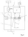
Figure 2 shows a schematic view of theFigure 1 electronic safety system; -
Figure 3 shows a schematic front view of a different embodiment of an electric household appliance featuring an electronic safety system in accordance with the present invention; -
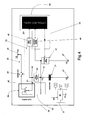
Figure 4 shows a block diagram of the electronic safety system installed in theFigure 3 appliance; -
Figure 5 shows a flow chart of the operations performed by the electronic safety system inFigure 4 ; -
Figure 6 shows a flow chart of the check operations performed by the electronic safety system inFigure 4 ; -
Figure 7 shows a schematic view of a different embodiment of the electronic safety system inFigure 4 ; -
Figure 8 shows a flow chart of the check operations performed by the electronic safety system inFigure 7 . -
Number 1 inFigure 1 indicates as a whole an electric household appliance substantially comprising acasing 2; alaundry drum 3 mounted insidecasing 2 to hold a given amount of laundry, and directly facing a laundry loading/unloadingopening 4 formed incasing 2; and anaccess door 5 fitted tocasing 2 to move, e.g. rotate, between an open position and a closed position opening and closingopening 4 respectively. -
Electric household appliance 1 may be a washing and/or drying machine or any similar appliance, and comprises anelectronic safety system 6 for determining a hazard condition - corresponding todoor 5 being opened when electric power supply to the appliance is cut off, i.e. during a power cut (blackout) - or a safety condition - corresponding todoor 5 not being opened during the power cut. -
Electronic safety system 6 is also designed to selectively disable or enable operation ofappliance 1 upon detecting the hazard or safety condition respectively. - In
Figures 1 and2 examples, the appliance comprises various internalelectric equipment 7, such as an electric motor, pumps, and various known electric devices; and amain power circuit 8 connecting internalelectric equipment 7 to amain power source 9 comprising, for example, an electric line at a predetermined supply voltage V1 of preferably, though not necessarily, about 230 V. -
Main power circuit 8 comprises apower branch 10 connecting the external electric power source toelectric equipment 7; anelectronic switch 11 located alongpower branch 10, and which switches to off or on to respectively disconnect or connectappliance 1 topower source 9; and anelectromechanical switch 14 located alongpower branch 10 and connected todoor 5 to open and close whendoor 5 is moved into the open and closed position respectively. - More specifically,
electronic switch 11 may preferably, though not necessarily, comprise a TRIAC which receives a control signal SCOM and, depending on control signal SCOM, switches to on or off to respectively enable or cut off electric power supply toelectric equipment 7. -
Electronic safety system 6 comprises a detectingmodule 12 for detecting the hazard or safety condition; and acontrol module 13 for selectively disabling or enablingelectronic switch 11 on detecting the hazard or safety condition respectively. - With reference to
Figure 2 , detectingmodule 12 comprises an electric detectingbranch 15 having a first terminal at a reference voltage V2 of preferably, though not necessarily, about V2=5V; and a movableelectric contact 16 located along electric detectingbranch 15 and movable between a work position closingelectric detecting branch 15 to set a second terminal to voltage V3=V2, and a rest position opening electric detectingbranch 15 to set the second terminal to voltage V3=0V. - Detecting
module 12 also comprises amechanism 18, which cooperates withdoor 5 to moveelectric contact 16 mechanically from the work position to the rest position whendoor 5 is moved from the closed to the open position. More specifically,mechanism 18 is designed not to moveelectric contact 16 in any way whendoor 5 moves from the open to the closed position. - Detecting
module 12 also comprises anelectromagnetic device 19 which, when excited, generates a magnetic field to moveelectric contact 16 from the rest position, i.e. opening, to the work position, i.e. closingelectric detecting branch 15. - In the example shown,
electromagnetic device 19 may comprise a coil which receives an excitation signal SE to generate a magnetic field to moveelectric contact 16 from the rest to the work position. -
Electric detecting branch 15 therefore generates at the second terminal a status signal ST indicating in code the hazard condition, whenelectric contact 16 is in the rest position corresponding to a zero voltage V3, or the safety condition whenelectric contact 16 is in the work position corresponding to voltage V3=V2. -
Control module 13 comprises a microprocessor having a first input connected to the second terminal ofelectric detecting branch 15 to receive status signal ST; a second input receiving a priority enabling signal SA; a first output supplying control signal SCOM toelectronic switch 11; and a second output supplying excitation signal SE toelectromagnetic device 19. - In the example shown, when signal ST indicates the hazard condition,
control module 13 generates control signal SCOM which disableselectronic switch 11; and, when signal ST indicates the safety condition,control module 13 generates control signal SCOM to enableelectronic switch 11. - Priority enabling signal SA may be generated by a
control interface 21 oncasing 2, to allow user consent to startappliance 1 after a power cut. In theFigure 2 example,control interface 21 comprises a button which is pressed by the user to supply priority enabling signal SA to the control module. - In the event of a power cut during a wash cycle of
appliance 1, the following situations may arise. - If
door 5 has remained closed throughout the power cut,electric contact 16 is in the work position, so electric detectingbranch 15 generates status signal ST indicating the safety condition. When power is restored,control module 13, receiving status signal ST indicating the safety condition, therefore generates control signal SCOM to enable the TRIAC and so allow the appliance to continue the wash cycle interrupted by the power cut. - Conversely, if
door 5 is opened during the power cut,mechanism 18 moveselectric contact 16 from the work position to the rest position. At this stage,electromagnetic device 19, receiving no excitation signal from the control module, generates no magnetic field, soelectric contact 16 remains in the rest position. Closure ofdoor 5 produces no movement ofelectric contact 16, which therefore remains in the rest position, thus generating a status signal ST indicating the hazard condition. - When power is restored,
control module 13 acquires the hazard condition indicated in status signal ST, and generates control signal SCOM to keepelectronic switch 11 disabled and so cut off power supply toelectric equipment 7. In which case,control module 13 keeps the TRIAC and, hence,appliance 1 disabled, and remains on standby awaiting priority enabling signal SA from the user. The standby condition terminates when the user presses the button to generate priority enabling signal SA. More specifically, on receiving priority enabling signal SA,control module 13 enables the TRIAC to allowappliance 1 to start operating again, and at the same time supplies excitation signal SE toelectromagnetic device 19 which moveselectric contact 16 into the work position. - According to the present invention as shown in
Figures 1 and2 and on the light of the above description, theelectronic safety system 6 is configured to: detecting the hazard condition corresponding to said access door being opened during a black out, or a safety condition corresponding to said access door not being opened during said black out; and selectively disabling or enabling said electronic switching means upon detection of said hazard condition or said safety condition respectively. - In detail,
electronic safety system 6 comprises detecting means 12 comprising anelectric contact 16 movable between a work position and a rest position;mechanical means 18 which cooperate with theaccess door 5 to move theelectric contact 16 from the work position to the rest position when theaccess door 5 is moved into open position; andelectromagnetic means 19 which generate a magnetic field to move theelectric contact 16 into work position. - In detail, the electronic control means 13 are configured to disable electronic switching means 11 when the
electric contact 16 is in rest position, or enable electronic switching means 11 when theelectric contact 16 is in work position. - More in detail, the
appliance 1 comprises interface means 21 on thecasing 2 to allow a user to generate a priority enabling signal SA enabling operation of theelectric household appliance 1. Upon receiving the priority enabling signal (SA), electronic control means 13 switching electronic switching means 11 from off to on. - Upon receiving said priority enabling signal SA, electronic control means 13 command said electromagnetic means 19 to generate a magnetic field to move the
electric contact 16 from said rest position to said work position. - More specifically,
mechanical means 18 are designed not to move theelectric contact 16 when theaccess door 5 is moved from the open position to closed position. - In detail the electronic switching means 11 comprise a TRIAC; electronic control means 13 comprise a microprocessor, whereas electromagnetic means 19 comprise an electric coil.
-
Electronic safety system 6 described above has the advantage of eliminating the hazard posed by the appliance starting up automatically after a power cut during which the appliance door has been opened. - Clearly, changes may be made to the electronic control device as described herein without, however, departing from the scope of the present invention as defined in the accompanying Claims.
- In detail,
Figures 3 and4 show a second embodiment of the present invention, wherein aelectronic safety system 30 is configured to detect a hazard condition caused bydoor 5 being opened during a blackout, and to discriminate between this and a "safety condition ", so as to automatically restart the appliance with no intervention on the part of the user. - In detail,
safety system 30 is configured to determine opening or closing ofdoor 5 during the blackout time interval Δt; and determine a "hazard condition" and, at the same time, setappliance 1 to a restart standby status when at least one opening ofdoor 5 during blackout time interval Δt is determined. - Additionally and preferably,
electronic safety system 30 is also configured to determine a "hazard condition" and, at the same time setappliance 1 to a restart standby status if the following conditions are met : no opening ofdoor 5 during blackout time interval Δt is determined and, at the same time, the blackout time interval Δt is greater than a predetermined safety time interval Δ1. - Finally,
electronic safety system 30 is configured to determine a "safety condition" and setrestart appliance 1 automatically, i.e. with no user assistance, from where operation was interrupted by the blackout, when no opening of the door during blackout time interval Δt is determined. - Preferably as additional safety measure, the
electronic safety system 30 is configured to determine a "safety condition" and setrestart appliance 1 automatically, i.e. with no user assistance, from where operation was interrupted by the blackout, when the following conditions are met: no opening of the door during blackout time interval Δt is determined and, at the same time, the determined blackout time interval Δt is less than the predetermined safety time interval Δ1. -
Figures 3 and4 show an example embodiment ofelectronic safety system 30, which substantially comprises acapacitor 31; acircuit 32 connected to aline 36 having a predetermined low voltage V2 of preferably, though not necessarily, 12 V; an electric capacitor discharge circuit 33; adoor switch 34 which is moved bydoor 5 between a closed position and an open position; and an high voltageelectronic switch 35 which switches to off or on to respectively disconnect or connect internalelectric equipments 7 of theappliance 1 to a highvoltage power line 9 having a predetermined high voltage V1 of preferably, though not necessarily, about 230 V. - In detail,
circuit 32 comprises alow voltage switch 39 which is movable, on the basis of a command signal SP, between a work position closingelectric circuit 32 to set a terminal to low voltage V2, and a rest position openingelectric circuit 32 to set the terminal to 0 V. - More specifically, closing
door 5 activatesdoor switch 34 electromechanically to switch to the closed position and connectpower line 36 tocapacitor 31. Accordingly, the voltage VS at asensing terminal 37 ofcapacitor 31 reaches a first value, i.e. corresponding to supply voltage VS=V2. - Conversely, opening
door 5 activatesdoor switch 34 electromechanically to switch to the open position (shown inFigure 4 ). In which case,door switch 34 connects sensingterminal 37 ofcapacitor 31 to electric capacitor discharge circuit 33, thus setting voltage VS of sensingterminal 37 ofcapacitor 31 to a value V3<V2, i.e. corresponding to a ground voltage VS=V3=0 V. -
Electronic safety system 30 also comprises asensing device 38, which measures voltage VS at sensingterminal 37 ofcapacitor 31 to discriminate, as a function of voltage VS, between a "hazard condition" caused bydoor 5 being opened during the blackout, and a "safety condition". - In the
Figure 4 embodiment,door switch 34 comprises three terminals, of which afirst terminal 40 is connected tocircuit 32 at voltage V2; asecond terminal 41 is connected to anode 42 in turn connected to electric capacitor discharge circuit 33 and to sensingterminal 37 ofcapacitor 31 via alow leakage device 43; and athird terminal 44 is connected directly to sensingterminal 37 ofcapacitor 31. - In the
Figure 4 example, closingdoor 5 switches door switch 34 to the closed position, in whichfirst terminal 40 is connected tosecond terminal 41, thus connectingsensing terminal 37 toline 36 overmain circuit 32. - Conversely, opening
door 5 switches door switch 34 to the open position, in whichsecond terminal 41 is disconnected frompower line 36 and connected tothird terminal 44, thus connectingsensing terminal 37 directly to electric capacitor discharge circuit 33. - With regard to high voltage
electronic switch 35, it may preferably comprise a relè configured to disconnect internalelectric equipments 7 of theappliance 1 to a highvoltage power line 9 when openingdoor 5 switches door switch 34 to the open position. - In addition, when door switch 34 is in close position, the
electronic switch 35 connect or conversely maintain disconnected internalelectric equipments 7 of theappliance 1 to the highvoltage power line 9 on the basis of a control signal SP. -
Capacitor 31 comprises sensingterminal 37 connected tonode 42 vialow leakage device 43; and a terminal 46 connected to aground line 47. - Electric capacitor discharge circuit 33 comprises a door
state sensing device 48 having an input terminal connected tonode 42, and an output terminal that supplies a measurement signal having a electrical value (voltage or current) which is a function of the voltage atnode 42. - Door
state sensing device 48 may, for example, comprise an R-C electric circuit (not shown) for discharging the electric charge accumulated bycapacitor 31; and an interface circuit (not shown) for generating the measurement signal as a function of the voltage atnode 42. -
Sensing device 38 comprises a capacitorcharge sensing device 49, which has an input terminal connected to sensingterminal 37, and an output terminal that supplies a logic measurement signal having a first logic level when the voltage at sensingterminal 37 equals voltage V2, and a second logic level when the voltage at sensingterminal 37 equals voltage V3. -
Sensing device 38 also comprises aprocessing unit 50, e.g. a microprocessor, having a terminal connected to the output terminal of doorstate sensing device 48 of electric capacitor discharge circuit 33 to receive the measurement signal; a terminal connected to the output terminal of capacitorcharge sensing device 49 to receive the logic measurement signal; and a control terminal that supplies the control signal SP to thehigh voltage switch 35 and tolow voltage switch 39. - In the
Figure 4 example,electronic safety system 30 preferably, though not necessarily, also comprises atest circuit 51, which cooperates withprocessing unit 50 to determine any malfunctioning of capacitorcharge sensing device 49. - More specifically, in the
Figure 4 example,test circuit 51 is connected parallel tocapacitor 31, and so has a terminal connected to sensingterminal 37 ofcapacitor 31; a terminal connected to groundline 47; and a terminal connected to processingunit 50. - The steps performed by
electronic safety system 30 will now be described with reference toFigure 5 , and as of a start condition in which the following are assumed:low voltage switch 39 ofcircuit 32 is closed;appliance 1 is running and performing the predetermined stage in the operating cycle, e.g. the spin stage of a wash cycle; anddoor 5 is closed. - At this stage,
door switch 34 is closed;node 42 andsensing terminal 37 are at a voltage equal to voltage V2=12V; thecapacitor 31 is fully charged andhigh voltage switch 35 is closed. - In the event of a blackout (block 100), processing
unit 50 opens low voltage switch 39 (block 110). A this step,low voltage switch 39 causehigh voltage switch 35 to open. - At this point,
electronic safety system 30 operates in three modes, depending on whetherdoor 5 is opened/closed, and the duration of blackout time interval Δt. - More specifically, a first operating mode (block 120) applies to
door 5 being opened during the blackout; a second operating mode (block 130) applies to door 5 not being opened, and to electric power being restored within a time interval Δt equal to or less than the predetermined safety time interval Δ1; and a third operating mode (block 140) applies to door 5 not being opened, and to the blackout terminating within a time interval Δt greater than the predetermined safety time interval Δ1. - More specifically, if opened during the blackout,
door 5 switches door switch 34 to open (block 150), thus connectingsensing terminal 37 ofcapacitor 31 to electric capacitor discharge circuit 33. - Accordingly, electric capacitor discharge circuit 33 discharges capacitor 31 (block 160) so the voltage VS at the
sensing terminal 37 goes from voltage VS=V2 to voltage VS=V3 (block 170). - At the end of the blackout (block 180), processing
unit 50 activates a check procedure to determine the charge ofcapacitor 31 and so determine whether or notdoor 5 was opened during the blackout. - At this step, processing
unit 50 measures the voltage VS=V3=0V at sensingterminal 37, and so determines, by means of capacitorcharge sensing device 49, the open state ofdoor 5. - Accordingly, processing
unit 50 determines a hazard condition (block 190) and setsappliance 1 to a standby state (block 210), in whichappliance 1 is not restarted at the end of the blackout. More in detail at thisstep processing unit 50 generates the command signal SP which maintain open thelow voltage switch 39 andhigh voltage switch 35. - The standby state is interrupted by a user command signal SA (YES output of block 210). On receiving command signal SA, processing
unit 50 generate the command signal SP to closelow voltage switch 39 andhigh voltage switch 35 so that theappliance 1 restarts from the operating stage, e.g. the spin stage, interrupted by the blackout (block 220). - In other words, if a hazard condition is determined as described above, processing
unit 50, before closing switches 35 and 39 and activating the operating cycle, waits for a command signal SA generated by the user pressing abutton 31 onappliance 1. - The second operating mode (block 130) applies to the blackout terminating within a time interval equal to or less than the safety time interval Δ1, and to
door 5 not being opened. - In this case,
door switch 34 remains closed (block 240), and sensingterminal 37 remains connected tonode 42 vialow leakage device 43. -
Capacitor 31 being discharged by capacitor discharge circuit 33 vialow leakage device 43, discharge is delayed in controlled manner by low leakage device 43 (block 250). - It should be pointed out that the safety time interval Δ1 is calculated so that voltage VS at sensing
terminal 37 remains at a substantially voltage V2 throughout safety time interval Δ1 (block 260). - When electric power is restored (block 270), processing
unit 50, detecting a substantially voltage V2 at sensingterminal 37, therefore determines no opening ofdoor 5 and, at the same time, a shorter blackout period Δt<=Δ1 (block 280), and so determines a safety condition (block 290). - Preferably, the
electronic safety system 30 can comprise atest circuit 51 for determining malfunctioning of said capacitorcharge sensing device 49; saidelectronic safety system 30 being configured to set theelectric household appliance 1 to a restart standby state when saidtest circuit 51 determines a malfunction of said capacitorcharge sensing device 49. - In this regards, processing
unit 50 may be configured to implement, viatest circuit 51, a check procedure to determine malfunctioning of capacitor charge sensing device 33 (block 300). - On detecting malfunctioning of capacitor charge sensing device 33 (NO output of block 300), processing
unit 50sets appliance 1 to a standby state (block 210), in whichappliance 1 is not restarted at the end of the blackout. - The standby state is interrupted by a user command signal SA (YES output of block 210). On receiving command signal SA, processing
unit 50 closes switches 35 and 39 by command signal SP so thatappliance 1 restarts from the operating stage, e.g. the spin stage, interrupted by the blackout (block 220). - Conversely, on detecting no malfunctioning of capacitor charge sensing device 33, without waiting for a user command signal (block 310), processing
unit 50 automatically closeshigh voltage switch 35 andlow voltage switch 39 so that the cycle is restarted from the stage interrupted by the blackout. - Finally, the third operating mode (block 140) applies to the blackout lasting longer than the safety time interval Δt>Δ1, and to
door 5 not being opened. - In which case,
door switch 34 remains closed (block 320), sensingterminal 37 remains connected tonode 42 vialow leakage device 43. At this time,high voltage switch 35 is opened. -
Low leakage device 43 therefore gradually dischargescapacitor 31 to bring voltage VS at sensingterminal 37 to a ground voltage VS=V3=0 (block 330). - At the end of the blackout (block 350), processing
unit 50 therefore determines a substantially low voltage VS=V3 at sensingterminal 37, and hence a hazard condition (block 370). - On detecting a hazard condition, processing
unit 50sets appliance 1 to a standby state pending user command signal SA (block 390). Indetail processing unit 50 generates command signal SP that maintains openhigh voltage switch 35. - On receiving command signal SA (YES output of block 390), processing
unit 50 generates command signal SP that closeshigh voltage switch 35 so thatappliance 1 restarts from the stage interrupted by the blackout (block 400). -
Figure 6 shows a flow chart of the check procedure operations performed byelectronic safety system 30 to determine malfunctioning of capacitor charge sensing device 33. - In this case,
test circuit 51 is assumed to substantially comprise an electronic switch, e.g. a transistor, controllable by processingunit 50 to dischargecapacitor 31 on command. - Processing
unit 50 opens the electronic switch and closes low voltage switch 39 (block 500) to charge capacitor 31 (block 510), and, once thecapacitor 31 is charged, determines by means of capacitor charge sensing device 49 (block 520) whether voltage VS at sensingterminal 37 equals voltage V2 (block 530). - If it does not (NO output of block 530), processing
unit 50 determines malfunctioning of capacitor charge sensing device 49 (block 540) and the procedure is terminated; conversely (YES output of block 530), processingunit 50 openslow voltage switch 39 and closes thehigh voltage switch 35, which completely discharges capacitor 31 (block 550). - At this point,' processing
unit 50 determines by means of capacitorcharge sensing device 49 whether voltage VS at sensingterminal 37 equals voltage V3 (block 560). If it does not (NO output of block 560), processingunit 50 determines malfunctioning of capacitor charge sensing device 49 (block 540); conversely (YES output of block 560), correct operation of capacitorcharge sensing device 49 is determined (block 570). - The electronic safety system described has the major advantage, on the one hand, of guaranteeing a high degree of safety in the event of a blackout, and, on the other, of being activated automatically when no hazard conditions are detected at the end of the blackout.
- The
Figure 7 embodiment relates to anelectronic safety system 60 similar toelectronic safety system 30, and the component parts of which are indicated, where possible, using the same reference numbers as for corresponding parts ofsystem 60. -
Electronic safety system 60 differs fromelectronic safety system 30 bytest circuit 51 being located betweenterminal 46 ofcapacitor 31 andground line 47, and having a control terminal connected to processingunit 50. - More specifically,
test circuit 51 is configured to set the voltage atterminal 46, on command, to a first reference value VZ=V3=0V or a second reference value
- With reference to
Figure 8 , processingunit 50 ofelectronic safety system 60commands test circuit 51 to set voltage VZ to the first reference value VZ=V3=0V, and, at the same time, closes low voltage switch 39 (block 600) to charge capacitor 31 (block 610). Once thecapacitor 31 is charged, processingunit 50 determines by means of capacitorcharge sensing device 49 whether voltage VS at sensing terminal 37 (block 620) equals voltage V2 (block 630). - If it does not (NO output of block 630), processing
unit 50 determines malfunctioning of capacitor charge sensing device 49 (block 640) and the procedure is terminated; conversely (YES output of block 630), processingunit 50 openslow voltage switch 39 and activatestest circuit 51, which sets the voltage atterminal 46 to second reference value VZ=V4=-12V (block 650). - At this point, processing
unit 50 determines by means of capacitorcharge sensing device 49 whether voltage VS at sensingterminal 11 equals voltage V3 (block 660). - If it does not (NO output of block 660), processing
unit 50 determines malfunctioning of capacitorcharge sensing device 49; conversely (YES output of block 660), correct operation of capacitorcharge sensing device 49 is determined (block 670).
Claims (15)
- An electric household appliance (1) comprising a casing (2); a laundry drum (3) housed inside the casing (2) and facing an opening (4) formed in said casing (2); an access door (5) fitted to the casing (2) to move between an open position and a closed position opening and closing said opening (4) respectively; electronic switching means (35) which switch to off or on to respectively disconnect or connect the electric household appliance (1) to a power line (9);
said electric household appliance (1) being characterized by comprising an electronic safety system (6)(30)(60) configured to:- detecting a hazard condition corresponding to said access door (5) being opened during a black out, or a safety condition corresponding to said access door (5) not being opened during said black out; and- selectively disabling or enabling said electronic switching means (35) upon detection of said hazard condition or said safety condition respectively. - An electric household appliance as claimed in Claim 1, wherein said electronic safety system (30) is configured to determine opening or closing of said door (5) during a blackout time interval (Δt); at the end of the blackout, said electronic safety system (30) (60) being configured to restart said electric household appliance (1) automatically from the operating stage interrupted by the blackout, when no opening of said door (5) during said blackout is determined.
- An electric household appliance as claimed in Claim 1 or 2, wherein said electronic safety system (30) is configured to determine opening or closing of said door (5) during a blackout time interval (Δt); at the end of the blackout, said electronic safety system (30)(60) being configured to restart said electric household appliance (1) automatically from the operating stage interrupted by the blackout, when the following conditions apply:- no opening of said door (5) during said blackout is determined and, at the same time,- the blackout time interval (Δt) is substantially less than a predetermined safety time interval (Δ1).
- An electric household appliance as claimed in Claims 2, wherein said electronic safety system (30)(60) is configured to set the electric household appliance (1) to a restart standby state, when at least one opening of the door during said blackout is determined.
- An electric household appliance as claimed in Claim 3, wherein said electronic safety system (30) (60) is configured to set the electric household appliance (1) to a restart standby state when no opening of said door (5) during the blackout time interval (Δt) is determined and, at the same time, the blackout time interval (Δt) is greater than said predetermined safety time interval (Δ1)
- An electric household appliance as claimed in any one of the foregoing Claims, wherein said electronic safety system (30)(60) comprises: at least one capacitor (31) and an electric capacitor discharge circuit (33) configured to discharge said capacitor (31) if the door is opened during said blackout time interval (Δt).
- An electric household appliance as claimed in claim 6, wherein said electronic safety system (30) (60) comprises: door switching means (34) that switch between a first switch position connecting a first terminal (37) of said capacitor (31) to a power line (36), so the capacitor (31) is charged and the voltage at the first terminal (37) reaches a predetermined first value (V2), and a second switch position connecting said first terminal (37) of said capacitor (31) to said electric capacitor discharge circuit (33), so as to discharge the capacitor (31) and set the voltage at the first terminal (37) to a predetermined second value (V3);
said door (5) being designed so that opening/closing it switches said door switching means (33) between said first and said second position;
and said electronic safety system (30)(60) also comprising sensing means (49, 50) for determining opening of said door (5) as a function of the first (V2) or second (V3) voltage value measured at the first terminal (37) of said capacitor (31). - An electric household appliance as claimed in Claim 7, and comprising a main switch (39) interposed between said door switching means (34) and said power line (36);
said electronic safety system (30) (60) being configured to open said main switch (39) when the blackout occurs, and comprising low leakage means (43) connected to said first terminal (37) of said capacitor (31) and designed to time discharge of said capacitor (31) when said main switch (39) is open and said door (5) remains closed during said blackout time interval (Δt). - An electric household appliance as claimed in Claim 8, wherein said main switch (39) is a low voltage switch and said power line (36) has a low voltage of about 12 V.
- An electric household appliance as claimed in Claims 7, 8 and 9, wherein said sensing means (38) comprise a processing unit (50); and a capacitor charge sensing device (49) connected to said first terminal (37) to measure the voltage (VS) at said first terminal (37), and configured to supply said processing unit (50) with a measurement signal having a first or a second level when the voltage (VS) measured at said first terminal (37) has said first (V2) or second (V3) voltage value respectively.
- An electric household appliance as claimed in Claim 10, wherein said electric capacitor discharge circuit (33) is connected to said processing unit (50) to supply it with a measurement signal, the voltage of which is related to opening/closing of said door (5).
- An electric household appliance as claimed in Claim 1, wherein said detecting means (12) comprise an electric contact (16) movable between a work position and a rest position; mechanical means (18) which cooperate with said access door (5) to move said electric contact (16) from said work position to said rest position when the access door (5) is moved into said open position; and electromagnetic means (19) which generate a magnetic field to move said electric contact (16) into said work position.
- An electric household appliance as claimed in Claim 12, wherein said electronic control means (13) disable said electronic switching means (11) when said electric contact (16) is in said rest position, or enable said electronic switching means (11) when said electric contact (16) is in said work position.
- An electric household appliance as claimed in Claim 13, and comprising interface manes (21) to allow a user to generate a priority enabling means signal (SA) enabling operation of said electric household appliance; upon receiving said priority enabling signal (SA), said electronic control means (13) switching said electronic switching means (11) from off to on, preferably upon receiving said priority enabling signal (SA), said electronic control means (13) command said electromagnetic means (19) to generate a magnetic field to move said electric contact (16) from said rest position to said work position.
- An electric household appliance as claimed in any one of Claims 12 to 14, wherein mechanical means (18) are designed not to move said electric contact (16) when said access door (5) is moved from said open position to said closed position.
Priority Applications (3)
| Application Number | Priority Date | Filing Date | Title |
|---|---|---|---|
| PL09006501T PL2123820T3 (en) | 2008-05-22 | 2009-05-14 | Electronic safety system for an electric household appliance with an access door |
| EP09006501A EP2123820B1 (en) | 2008-05-22 | 2009-05-14 | Electronic safety system for an electric household appliance with an access door |
| RU2009119294/12A RU2497989C2 (en) | 2008-05-22 | 2009-05-21 | Electronic safety system for household appliance with door |
Applications Claiming Priority (2)
| Application Number | Priority Date | Filing Date | Title |
|---|---|---|---|
| EP08156770A EP2123819A1 (en) | 2008-05-22 | 2008-05-22 | Electronic control device for an electric household appliance with an access door |
| EP09006501A EP2123820B1 (en) | 2008-05-22 | 2009-05-14 | Electronic safety system for an electric household appliance with an access door |
Publications (2)
| Publication Number | Publication Date |
|---|---|
| EP2123820A1 true EP2123820A1 (en) | 2009-11-25 |
| EP2123820B1 EP2123820B1 (en) | 2011-08-24 |
Family
ID=39769527
Family Applications (2)
| Application Number | Title | Priority Date | Filing Date |
|---|---|---|---|
| EP08156770A Withdrawn EP2123819A1 (en) | 2008-05-22 | 2008-05-22 | Electronic control device for an electric household appliance with an access door |
| EP09006501A Not-in-force EP2123820B1 (en) | 2008-05-22 | 2009-05-14 | Electronic safety system for an electric household appliance with an access door |
Family Applications Before (1)
| Application Number | Title | Priority Date | Filing Date |
|---|---|---|---|
| EP08156770A Withdrawn EP2123819A1 (en) | 2008-05-22 | 2008-05-22 | Electronic control device for an electric household appliance with an access door |
Country Status (5)
| Country | Link |
|---|---|
| EP (2) | EP2123819A1 (en) |
| AT (1) | ATE521748T1 (en) |
| ES (1) | ES2372659T3 (en) |
| PL (1) | PL2123820T3 (en) |
| RU (1) | RU2497989C2 (en) |
Cited By (1)
| Publication number | Priority date | Publication date | Assignee | Title |
|---|---|---|---|---|
| EP2569476B1 (en) | 2010-05-14 | 2015-06-03 | Electrolux Home Products Corporation N.V. | Heating circuit with monitoring arrangement for a household appliance |
Families Citing this family (2)
| Publication number | Priority date | Publication date | Assignee | Title |
|---|---|---|---|---|
| WO2015000530A1 (en) * | 2013-07-05 | 2015-01-08 | Arcelik Anonim Sirketi | Laundry treatment appliance having improved door safety |
| WO2020228941A1 (en) * | 2019-05-13 | 2020-11-19 | Electrolux Appliances Aktiebolag | Laundry-treating machine and method for controlling such a laundry-treating machine |
Citations (4)
| Publication number | Priority date | Publication date | Assignee | Title |
|---|---|---|---|---|
| US4056891A (en) * | 1975-05-23 | 1977-11-08 | Billy R. Rayburn | Sequential switching device |
| US4461940A (en) * | 1980-08-29 | 1984-07-24 | Matsushita Electric Industrial Co., Ltd. | Fail-safe device for use in a heating apparatus |
| US5276284A (en) * | 1992-02-28 | 1994-01-04 | Square D Company | Power switch disabler |
| US20030197387A1 (en) * | 2002-04-23 | 2003-10-23 | Albert Dirnberger | Door lock |
Family Cites Families (5)
| Publication number | Priority date | Publication date | Assignee | Title |
|---|---|---|---|---|
| IT1309106B1 (en) * | 1999-10-13 | 2002-01-16 | Merloni Elettrodomestici Spa | ELECTRONICALLY CONTROLLED DOMESTIC ELECTRICITY USER AND RELATED CONTROL AND PROGRAMMING SYSTEM. |
| ATE449227T1 (en) * | 2002-02-27 | 2009-12-15 | Emz Hanauer Gmbh & Co Kgaa | UNIT WITH MEMORY METAL ACTUATOR FOR DOOR LOCKS OF HOUSEHOLD APPLIANCES |
| ES2277231T3 (en) * | 2004-07-13 | 2007-07-01 | C.R.F. Societa Consortile Per Azioni | APPLIANCE APPLIANCE, IN PARTICULAR, MACHINE FOR WASHING AND / OR DRYING A DOOR INTERLOCK / RELEASE DEVICE THAT CAN BE ELECTRICALLY OPERATED. |
| SI21888A (en) * | 2004-10-06 | 2006-04-30 | Itw Metalflex D.O.O. Tolmin | Safety lock of doors in household appliances |
| ITTO20060736A1 (en) * | 2006-10-13 | 2008-04-14 | Itw Metalflex Druzba Za Proizvodnjo Delov Za ... | LOCKING DEVICE FOR A DOOR OF A HOUSEHOLD APPLIANCE, IN PARTICULAR A PORT OF A WASHING MACHINE |
-
2008
- 2008-05-22 EP EP08156770A patent/EP2123819A1/en not_active Withdrawn
-
2009
- 2009-05-14 EP EP09006501A patent/EP2123820B1/en not_active Not-in-force
- 2009-05-14 PL PL09006501T patent/PL2123820T3/en unknown
- 2009-05-14 ES ES09006501T patent/ES2372659T3/en active Active
- 2009-05-14 AT AT09006501T patent/ATE521748T1/en not_active IP Right Cessation
- 2009-05-21 RU RU2009119294/12A patent/RU2497989C2/en active
Patent Citations (4)
| Publication number | Priority date | Publication date | Assignee | Title |
|---|---|---|---|---|
| US4056891A (en) * | 1975-05-23 | 1977-11-08 | Billy R. Rayburn | Sequential switching device |
| US4461940A (en) * | 1980-08-29 | 1984-07-24 | Matsushita Electric Industrial Co., Ltd. | Fail-safe device for use in a heating apparatus |
| US5276284A (en) * | 1992-02-28 | 1994-01-04 | Square D Company | Power switch disabler |
| US20030197387A1 (en) * | 2002-04-23 | 2003-10-23 | Albert Dirnberger | Door lock |
Cited By (1)
| Publication number | Priority date | Publication date | Assignee | Title |
|---|---|---|---|---|
| EP2569476B1 (en) | 2010-05-14 | 2015-06-03 | Electrolux Home Products Corporation N.V. | Heating circuit with monitoring arrangement for a household appliance |
Also Published As
| Publication number | Publication date |
|---|---|
| RU2497989C2 (en) | 2013-11-10 |
| EP2123820B1 (en) | 2011-08-24 |
| PL2123820T3 (en) | 2012-01-31 |
| EP2123819A1 (en) | 2009-11-25 |
| ATE521748T1 (en) | 2011-09-15 |
| ES2372659T3 (en) | 2012-01-25 |
| RU2009119294A (en) | 2010-11-27 |
Similar Documents
| Publication | Publication Date | Title |
|---|---|---|
| US10069292B2 (en) | Leakage current detection device for appliances | |
| US8836173B2 (en) | Domestic appliance having automatic switch-off | |
| US8421275B2 (en) | Apparatus for providing zero standby power control in an appliance | |
| US6597144B2 (en) | Method and apparatus for power loss detection and saving of operation settings in an appliance | |
| US20020138160A1 (en) | Apparatus for power failure identification in a programmable household appliance and method for identifying power failure | |
| EP2407851B1 (en) | Household appliance circuit arrangement | |
| EP2372493B1 (en) | Device for reducing standby-mode energy consumption of an electric household appliance | |
| EP2123820B1 (en) | Electronic safety system for an electric household appliance with an access door | |
| CN111519386B (en) | Auxiliary power supply of washing machine | |
| JP5784431B2 (en) | Load driving device and washing machine | |
| CN113811648B (en) | Laundry machine and method for controlling such laundry machine | |
| CN113131441B (en) | Motor protector and method for operating motor protector | |
| JP2002355212A (en) | Power failure recovery type dishwasher / dryer recovery type fully automatic washer / dryer and power failure recovery type electrical equipment | |
| JP2015026104A (en) | Electrical equipment | |
| KR101018474B1 (en) | Relay Control Method for Kimchi Refrigerator Compressor | |
| WO2015011863A1 (en) | Electrical appliance | |
| JP2015023900A (en) | Control device for electrical equipment | |
| JP2015023897A (en) | Electrical apparatus | |
| CN109477280B (en) | Door monitoring circuit for household appliance | |
| JP2012155996A5 (en) | ||
| KR20050079512A (en) | Reset protection circuit for embedded terminal |
Legal Events
| Date | Code | Title | Description |
|---|---|---|---|
| PUAI | Public reference made under article 153(3) epc to a published international application that has entered the european phase |
Free format text: ORIGINAL CODE: 0009012 |
|
| AK | Designated contracting states |
Kind code of ref document: A1 Designated state(s): AT BE BG CH CY CZ DE DK EE ES FI FR GB GR HR HU IE IS IT LI LT LU LV MC MK MT NL NO PL PT RO SE SI SK TR |
|
| 17P | Request for examination filed |
Effective date: 20100525 |
|
| 17Q | First examination report despatched |
Effective date: 20100615 |
|
| GRAP | Despatch of communication of intention to grant a patent |
Free format text: ORIGINAL CODE: EPIDOSNIGR1 |
|
| RAP1 | Party data changed (applicant data changed or rights of an application transferred) |
Owner name: ELECTROLUX HOME PRODUCTS CORPORATION N.V. |
|
| GRAS | Grant fee paid |
Free format text: ORIGINAL CODE: EPIDOSNIGR3 |
|
| RAP1 | Party data changed (applicant data changed or rights of an application transferred) |
Owner name: ELECTROLUX HOME PRODUCTS CORPORATION N.V. |
|
| GRAA | (expected) grant |
Free format text: ORIGINAL CODE: 0009210 |
|
| AK | Designated contracting states |
Kind code of ref document: B1 Designated state(s): AT BE BG CH CY CZ DE DK EE ES FI FR GB GR HR HU IE IS IT LI LT LU LV MC MK MT NL NO PL PT RO SE SI SK TR |
|
| REG | Reference to a national code |
Ref country code: GB Ref legal event code: FG4D |
|
| REG | Reference to a national code |
Ref country code: CH Ref legal event code: EP |
|
| REG | Reference to a national code |
Ref country code: IE Ref legal event code: FG4D |
|
| REG | Reference to a national code |
Ref country code: DE Ref legal event code: R096 Ref document number: 602009002220 Country of ref document: DE Effective date: 20111124 |
|
| REG | Reference to a national code |
Ref country code: NL Ref legal event code: VDEP Effective date: 20110824 |
|
| LTIE | Lt: invalidation of european patent or patent extension |
Effective date: 20110824 |
|
| REG | Reference to a national code |
Ref country code: ES Ref legal event code: FG2A Ref document number: 2372659 Country of ref document: ES Kind code of ref document: T3 Effective date: 20120125 |
|
| PG25 | Lapsed in a contracting state [announced via postgrant information from national office to epo] |
Ref country code: NL Free format text: LAPSE BECAUSE OF FAILURE TO SUBMIT A TRANSLATION OF THE DESCRIPTION OR TO PAY THE FEE WITHIN THE PRESCRIBED TIME-LIMIT Effective date: 20110824 Ref country code: SE Free format text: LAPSE BECAUSE OF FAILURE TO SUBMIT A TRANSLATION OF THE DESCRIPTION OR TO PAY THE FEE WITHIN THE PRESCRIBED TIME-LIMIT Effective date: 20110824 Ref country code: FI Free format text: LAPSE BECAUSE OF FAILURE TO SUBMIT A TRANSLATION OF THE DESCRIPTION OR TO PAY THE FEE WITHIN THE PRESCRIBED TIME-LIMIT Effective date: 20110824 Ref country code: PT Free format text: LAPSE BECAUSE OF FAILURE TO SUBMIT A TRANSLATION OF THE DESCRIPTION OR TO PAY THE FEE WITHIN THE PRESCRIBED TIME-LIMIT Effective date: 20111226 Ref country code: HR Free format text: LAPSE BECAUSE OF FAILURE TO SUBMIT A TRANSLATION OF THE DESCRIPTION OR TO PAY THE FEE WITHIN THE PRESCRIBED TIME-LIMIT Effective date: 20110824 Ref country code: NO Free format text: LAPSE BECAUSE OF FAILURE TO SUBMIT A TRANSLATION OF THE DESCRIPTION OR TO PAY THE FEE WITHIN THE PRESCRIBED TIME-LIMIT Effective date: 20111124 Ref country code: LT Free format text: LAPSE BECAUSE OF FAILURE TO SUBMIT A TRANSLATION OF THE DESCRIPTION OR TO PAY THE FEE WITHIN THE PRESCRIBED TIME-LIMIT Effective date: 20110824 Ref country code: IS Free format text: LAPSE BECAUSE OF FAILURE TO SUBMIT A TRANSLATION OF THE DESCRIPTION OR TO PAY THE FEE WITHIN THE PRESCRIBED TIME-LIMIT Effective date: 20111224 |
|
| REG | Reference to a national code |
Ref country code: PL Ref legal event code: T3 |
|
| REG | Reference to a national code |
Ref country code: AT Ref legal event code: MK05 Ref document number: 521748 Country of ref document: AT Kind code of ref document: T Effective date: 20110824 |
|
| PG25 | Lapsed in a contracting state [announced via postgrant information from national office to epo] |
Ref country code: CY Free format text: LAPSE BECAUSE OF FAILURE TO SUBMIT A TRANSLATION OF THE DESCRIPTION OR TO PAY THE FEE WITHIN THE PRESCRIBED TIME-LIMIT Effective date: 20110824 Ref country code: AT Free format text: LAPSE BECAUSE OF FAILURE TO SUBMIT A TRANSLATION OF THE DESCRIPTION OR TO PAY THE FEE WITHIN THE PRESCRIBED TIME-LIMIT Effective date: 20110824 Ref country code: GR Free format text: LAPSE BECAUSE OF FAILURE TO SUBMIT A TRANSLATION OF THE DESCRIPTION OR TO PAY THE FEE WITHIN THE PRESCRIBED TIME-LIMIT Effective date: 20111125 Ref country code: LV Free format text: LAPSE BECAUSE OF FAILURE TO SUBMIT A TRANSLATION OF THE DESCRIPTION OR TO PAY THE FEE WITHIN THE PRESCRIBED TIME-LIMIT Effective date: 20110824 Ref country code: SI Free format text: LAPSE BECAUSE OF FAILURE TO SUBMIT A TRANSLATION OF THE DESCRIPTION OR TO PAY THE FEE WITHIN THE PRESCRIBED TIME-LIMIT Effective date: 20110824 |
|
| PG25 | Lapsed in a contracting state [announced via postgrant information from national office to epo] |
Ref country code: BE Free format text: LAPSE BECAUSE OF FAILURE TO SUBMIT A TRANSLATION OF THE DESCRIPTION OR TO PAY THE FEE WITHIN THE PRESCRIBED TIME-LIMIT Effective date: 20110824 |
|
| PG25 | Lapsed in a contracting state [announced via postgrant information from national office to epo] |
Ref country code: CZ Free format text: LAPSE BECAUSE OF FAILURE TO SUBMIT A TRANSLATION OF THE DESCRIPTION OR TO PAY THE FEE WITHIN THE PRESCRIBED TIME-LIMIT Effective date: 20110824 Ref country code: SK Free format text: LAPSE BECAUSE OF FAILURE TO SUBMIT A TRANSLATION OF THE DESCRIPTION OR TO PAY THE FEE WITHIN THE PRESCRIBED TIME-LIMIT Effective date: 20110824 |
|
| PG25 | Lapsed in a contracting state [announced via postgrant information from national office to epo] |
Ref country code: RO Free format text: LAPSE BECAUSE OF FAILURE TO SUBMIT A TRANSLATION OF THE DESCRIPTION OR TO PAY THE FEE WITHIN THE PRESCRIBED TIME-LIMIT Effective date: 20110824 Ref country code: EE Free format text: LAPSE BECAUSE OF FAILURE TO SUBMIT A TRANSLATION OF THE DESCRIPTION OR TO PAY THE FEE WITHIN THE PRESCRIBED TIME-LIMIT Effective date: 20110824 |
|
| PG25 | Lapsed in a contracting state [announced via postgrant information from national office to epo] |
Ref country code: DK Free format text: LAPSE BECAUSE OF FAILURE TO SUBMIT A TRANSLATION OF THE DESCRIPTION OR TO PAY THE FEE WITHIN THE PRESCRIBED TIME-LIMIT Effective date: 20110824 |
|
| PLBE | No opposition filed within time limit |
Free format text: ORIGINAL CODE: 0009261 |
|
| STAA | Information on the status of an ep patent application or granted ep patent |
Free format text: STATUS: NO OPPOSITION FILED WITHIN TIME LIMIT |
|
| 26N | No opposition filed |
Effective date: 20120525 |
|
| REG | Reference to a national code |
Ref country code: DE Ref legal event code: R097 Ref document number: 602009002220 Country of ref document: DE Effective date: 20120525 |
|
| PG25 | Lapsed in a contracting state [announced via postgrant information from national office to epo] |
Ref country code: MC Free format text: LAPSE BECAUSE OF NON-PAYMENT OF DUE FEES Effective date: 20120531 |
|
| PGFP | Annual fee paid to national office [announced via postgrant information from national office to epo] |
Ref country code: ES Payment date: 20120525 Year of fee payment: 4 |
|
| REG | Reference to a national code |
Ref country code: IE Ref legal event code: MM4A |
|
| PG25 | Lapsed in a contracting state [announced via postgrant information from national office to epo] |
Ref country code: MK Free format text: LAPSE BECAUSE OF FAILURE TO SUBMIT A TRANSLATION OF THE DESCRIPTION OR TO PAY THE FEE WITHIN THE PRESCRIBED TIME-LIMIT Effective date: 20110824 |
|
| PG25 | Lapsed in a contracting state [announced via postgrant information from national office to epo] |
Ref country code: IE Free format text: LAPSE BECAUSE OF NON-PAYMENT OF DUE FEES Effective date: 20120514 |
|
| PG25 | Lapsed in a contracting state [announced via postgrant information from national office to epo] |
Ref country code: BG Free format text: LAPSE BECAUSE OF FAILURE TO SUBMIT A TRANSLATION OF THE DESCRIPTION OR TO PAY THE FEE WITHIN THE PRESCRIBED TIME-LIMIT Effective date: 20111124 |
|
| PG25 | Lapsed in a contracting state [announced via postgrant information from national office to epo] |
Ref country code: MT Free format text: LAPSE BECAUSE OF FAILURE TO SUBMIT A TRANSLATION OF THE DESCRIPTION OR TO PAY THE FEE WITHIN THE PRESCRIBED TIME-LIMIT Effective date: 20110824 |
|
| PGFP | Annual fee paid to national office [announced via postgrant information from national office to epo] |
Ref country code: PL Payment date: 20130425 Year of fee payment: 5 |
|
| REG | Reference to a national code |
Ref country code: CH Ref legal event code: PL |
|
| PG25 | Lapsed in a contracting state [announced via postgrant information from national office to epo] |
Ref country code: CH Free format text: LAPSE BECAUSE OF NON-PAYMENT OF DUE FEES Effective date: 20130531 Ref country code: LI Free format text: LAPSE BECAUSE OF NON-PAYMENT OF DUE FEES Effective date: 20130531 |
|
| PG25 | Lapsed in a contracting state [announced via postgrant information from national office to epo] |
Ref country code: TR Free format text: LAPSE BECAUSE OF FAILURE TO SUBMIT A TRANSLATION OF THE DESCRIPTION OR TO PAY THE FEE WITHIN THE PRESCRIBED TIME-LIMIT Effective date: 20110824 |
|
| PG25 | Lapsed in a contracting state [announced via postgrant information from national office to epo] |
Ref country code: LU Free format text: LAPSE BECAUSE OF NON-PAYMENT OF DUE FEES Effective date: 20120514 |
|
| PG25 | Lapsed in a contracting state [announced via postgrant information from national office to epo] |
Ref country code: HU Free format text: LAPSE BECAUSE OF FAILURE TO SUBMIT A TRANSLATION OF THE DESCRIPTION OR TO PAY THE FEE WITHIN THE PRESCRIBED TIME-LIMIT Effective date: 20090514 |
|
| PG25 | Lapsed in a contracting state [announced via postgrant information from national office to epo] |
Ref country code: PL Free format text: LAPSE BECAUSE OF NON-PAYMENT OF DUE FEES Effective date: 20140514 |
|
| REG | Reference to a national code |
Ref country code: PL Ref legal event code: LAPE |
|
| REG | Reference to a national code |
Ref country code: ES Ref legal event code: FD2A Effective date: 20151230 |
|
| PG25 | Lapsed in a contracting state [announced via postgrant information from national office to epo] |
Ref country code: ES Free format text: LAPSE BECAUSE OF NON-PAYMENT OF DUE FEES Effective date: 20140515 |
|
| REG | Reference to a national code |
Ref country code: FR Ref legal event code: PLFP Year of fee payment: 8 |
|
| REG | Reference to a national code |
Ref country code: FR Ref legal event code: PLFP Year of fee payment: 9 |
|
| REG | Reference to a national code |
Ref country code: FR Ref legal event code: PLFP Year of fee payment: 10 |
|
| PGFP | Annual fee paid to national office [announced via postgrant information from national office to epo] |
Ref country code: IT Payment date: 20220524 Year of fee payment: 14 Ref country code: GB Payment date: 20220520 Year of fee payment: 14 Ref country code: FR Payment date: 20220523 Year of fee payment: 14 Ref country code: DE Payment date: 20220519 Year of fee payment: 14 |
|
| REG | Reference to a national code |
Ref country code: DE Ref legal event code: R119 Ref document number: 602009002220 Country of ref document: DE |
|
| GBPC | Gb: european patent ceased through non-payment of renewal fee |
Effective date: 20230514 |
|
| PG25 | Lapsed in a contracting state [announced via postgrant information from national office to epo] |
Ref country code: IT Free format text: LAPSE BECAUSE OF NON-PAYMENT OF DUE FEES Effective date: 20230514 Ref country code: DE Free format text: LAPSE BECAUSE OF NON-PAYMENT OF DUE FEES Effective date: 20231201 Ref country code: GB Free format text: LAPSE BECAUSE OF NON-PAYMENT OF DUE FEES Effective date: 20230514 |
|
| PG25 | Lapsed in a contracting state [announced via postgrant information from national office to epo] |
Ref country code: FR Free format text: LAPSE BECAUSE OF NON-PAYMENT OF DUE FEES Effective date: 20230531 |