EP2123554A1 - Aircraft window member, its manufacturing method, and aircraft window assembly - Google Patents
Aircraft window member, its manufacturing method, and aircraft window assembly Download PDFInfo
- Publication number
- EP2123554A1 EP2123554A1 EP08711500A EP08711500A EP2123554A1 EP 2123554 A1 EP2123554 A1 EP 2123554A1 EP 08711500 A EP08711500 A EP 08711500A EP 08711500 A EP08711500 A EP 08711500A EP 2123554 A1 EP2123554 A1 EP 2123554A1
- Authority
- EP
- European Patent Office
- Prior art keywords
- film
- window
- main body
- aircraft
- conductive mesh
- Prior art date
- Legal status (The legal status is an assumption and is not a legal conclusion. Google has not performed a legal analysis and makes no representation as to the accuracy of the status listed.)
- Granted
Links
Images

Classifications
-
- B—PERFORMING OPERATIONS; TRANSPORTING
- B64—AIRCRAFT; AVIATION; COSMONAUTICS
- B64C—AEROPLANES; HELICOPTERS
- B64C1/00—Fuselages; Constructional features common to fuselages, wings, stabilising surfaces or the like
- B64C1/14—Windows; Doors; Hatch covers or access panels; Surrounding frame structures; Canopies; Windscreens accessories therefor, e.g. pressure sensors, water deflectors, hinges, seals, handles, latches, windscreen wipers
- B64C1/1476—Canopies; Windscreens or similar transparent elements
- B64C1/1484—Windows
-
- B—PERFORMING OPERATIONS; TRANSPORTING
- B64—AIRCRAFT; AVIATION; COSMONAUTICS
- B64D—EQUIPMENT FOR FITTING IN OR TO AIRCRAFT; FLIGHT SUITS; PARACHUTES; ARRANGEMENT OR MOUNTING OF POWER PLANTS OR PROPULSION TRANSMISSIONS IN AIRCRAFT
- B64D45/00—Aircraft indicators or protectors not otherwise provided for
- B64D45/0015—Devices specially adapted for the protection against criminal attack, e.g. anti-hijacking systems
- B64D45/0063—Devices specially adapted for the protection against criminal attack, e.g. anti-hijacking systems by avoiding the use of electronic equipment during flight, e.g. of mobile phones or laptops
-
- H—ELECTRICITY
- H05—ELECTRIC TECHNIQUES NOT OTHERWISE PROVIDED FOR
- H05K—PRINTED CIRCUITS; CASINGS OR CONSTRUCTIONAL DETAILS OF ELECTRIC APPARATUS; MANUFACTURE OF ASSEMBLAGES OF ELECTRICAL COMPONENTS
- H05K9/00—Screening of apparatus or components against electric or magnetic fields
- H05K9/0073—Shielding materials
- H05K9/0081—Electromagnetic shielding materials, e.g. EMI, RFI shielding
- H05K9/0086—Electromagnetic shielding materials, e.g. EMI, RFI shielding comprising a single discontinuous metallic layer on an electrically insulating supporting structure, e.g. metal grid, perforated metal foil, film, aggregated flakes, sintering
-
- H—ELECTRICITY
- H05—ELECTRIC TECHNIQUES NOT OTHERWISE PROVIDED FOR
- H05K—PRINTED CIRCUITS; CASINGS OR CONSTRUCTIONAL DETAILS OF ELECTRIC APPARATUS; MANUFACTURE OF ASSEMBLAGES OF ELECTRICAL COMPONENTS
- H05K9/00—Screening of apparatus or components against electric or magnetic fields
- H05K9/0073—Shielding materials
- H05K9/0094—Shielding materials being light-transmitting, e.g. transparent, translucent
-
- Y—GENERAL TAGGING OF NEW TECHNOLOGICAL DEVELOPMENTS; GENERAL TAGGING OF CROSS-SECTIONAL TECHNOLOGIES SPANNING OVER SEVERAL SECTIONS OF THE IPC; TECHNICAL SUBJECTS COVERED BY FORMER USPC CROSS-REFERENCE ART COLLECTIONS [XRACs] AND DIGESTS
- Y10—TECHNICAL SUBJECTS COVERED BY FORMER USPC
- Y10T—TECHNICAL SUBJECTS COVERED BY FORMER US CLASSIFICATION
- Y10T156/00—Adhesive bonding and miscellaneous chemical manufacture
- Y10T156/10—Methods of surface bonding and/or assembly therefor
-
- Y—GENERAL TAGGING OF NEW TECHNOLOGICAL DEVELOPMENTS; GENERAL TAGGING OF CROSS-SECTIONAL TECHNOLOGIES SPANNING OVER SEVERAL SECTIONS OF THE IPC; TECHNICAL SUBJECTS COVERED BY FORMER USPC CROSS-REFERENCE ART COLLECTIONS [XRACs] AND DIGESTS
- Y10—TECHNICAL SUBJECTS COVERED BY FORMER USPC
- Y10T—TECHNICAL SUBJECTS COVERED BY FORMER US CLASSIFICATION
- Y10T442/00—Fabric [woven, knitted, or nonwoven textile or cloth, etc.]
- Y10T442/10—Scrim [e.g., open net or mesh, gauze, loose or open weave or knit, etc.]
Definitions
- the present invention relates to an aircraft window member, a method of manufacturing the same, and an aircraft window assembly.
- aircraft window members are frequently used for canopies and cabin windows, for example. Endowing such aircraft window members with electromagnetic-wave shielding properties has been examined in order to avoid penetration of harmful electromagnetic waves from the outside of the aircraft or to prevent electromagnetic waves originating in the aircraft from leaking to the outside.
- Patent Document 1 discloses a manufacturing method in which a metal mesh for electromagnetic-wave shielding is formed on a film and is then attached to a window main body.
- Patent Document 1 Japanese Unexamined Patent Application, Publication No. 2005-104310 (FIG. 5)
- PET polyethylene terephthalate
- Acrylic resin is used for the window main body of each of the aircraft window members, and acrylic resin and PET have a large difference in thermal expansion coefficient. Therefore, when heat treatment is applied after the film is attached to the window main body, wrinkles may occur due to the difference in thermal expansion coefficient. Furthermore, the film may be peeled from the window main body during the operation of the aircraft because of a large temperature difference between when it is on the ground and when it is flying, which is undesirable in terms of durability.
- the present invention has been made in view of those circumstances, and an object of the present invention is to provide an aircraft window member excellent in durability, a method of manufacturing the same, and an aircraft window assembly.
- an aircraft window member according to the present invention includes: a film made of acrylic resin; a conductive mesh which is formed on the film and in which a conductive material is formed in a mesh shape so as to have optical transparency for ensuring visibility and to have electromagnetic-wave shielding properties; and a window main body which is made of acrylic resin and to which the film on which the conductive mesh is formed is attached.
- the window main body and the film are made of acrylic resin, they have an equivalent thermal expansion coefficient. Therefore, even when they are heated and cooled during manufacturing, hardly any wrinkles occur. Furthermore, although the aircraft window member is exposed to a large change in temperature during the operation of the aircraft, since there is no difference in thermal expansion coefficient between the window main body and the film, peeling of the film almost never occurs, thus improving the durability.
- the aircraft window member according to the present invention may have a configuration in which an adhesive layer is formed between the film on which the conductive mesh is formed and the window main body; and the adhesive layer is made of urethane adhesive.
- PVB polyvinyl butyral
- urethane adhesive has sufficient adhesive strength to bond the film made of acrylic resin to the window main body made of acrylic resin. It is preferable that film-like polyurethane be used as the urethane adhesive used in the present invention.
- the conductive mesh formed on the film may be located between the film and the window main body.
- the conductive mesh formed on the film is located between the film and the window main body, the conductive material of the conductive mesh and the adhesive layer are brought into direct contact.
- Urethane adhesive is used as the adhesive layer, and the urethane adhesive does not include plasticizer, unlike PVB. Therefore, a reaction does not occur between the conductive material of the conductive mesh and the adhesive layer, and there is no adverse influence on the optical transparency of the window member.
- the aircraft window member according to the present invention may have a configuration in which the conductive mesh is located above the window main body with the film therebetween; and a protective layer is formed on the conductive mesh in such a manner as to provide an exposed region used for an electrical connection at an edge portion of the conductive mesh.
- the protective layer When the conductive mesh formed on the film does not face the window main body but is located at the side opposite to the window main body with the film therebetween, it is necessary to laminate the protective layer to protect the conductive mesh. If the exposed region which is not covered with the protective layer is provided at the edge portion of the conductive mesh when the protective layer is laminated, it is possible to obtain an electrical connection for electromagnetic-wave shielding by using the exposed region for the electrical connection.
- an aircraft window assembly includes: any of the aircraft window members described above; and a window frame which holds the aircraft window member.
- the aircraft window assembly excellent in durability can be provided.
- an aircraft-window-member manufacturing method includes attaching a film that is made of acrylic resin and that holds a conductive mesh in which a conductive material is formed in a mesh shape so as to have optical transparency for ensuring visibility and to have electromagnetic-wave shielding properties, to a window main body made of acrylic resin.
- the aircraft window member can be simply manufactured just by attaching the film to the window main body. Even when the window main body has a curved face, the film can be easily attached thereto because the film has flexibility. Since the window main body and the film are made of acrylic resin, they have an equivalent thermal expansion coefficient. Therefore, even when they are heated and cooled during manufacturing, hardly any wrinkles occur. Furthermore, although the aircraft window member is exposed to a large change in temperature during the operation of the aircraft, since there is no difference in the thermal expansion coefficient between the window main body and the film, peeling of the film almost never occurs, thus improving the durability.
- the film may be attached to the window main body after an adhesive layer made of urethane adhesive is provided on the window main body.
- PVB polyvinyl butyral
- urethane adhesive has sufficient adhesive strength to bond the film made of acrylic resin to the window main body made of acrylic resin.
- the film may be attached to the window main body so as to locate the conductive mesh between the film and the window main body.
- the conductive mesh formed on the film is located between the film and the window main body, the conductive material of the conductive mesh and the adhesive layer are brought into direct contact.
- Urethane adhesive is used as the adhesive layer, and the urethane adhesive does not include plasticizer, unlike PVB. Therefore, a reaction does not occur between the conductive material of the conductive mesh and the adhesive layer, and there is no adverse influence on the optical transparency of the window member.
- the aircraft-window-member manufacturing method according to the present invention may have a configuration in which the film is attached to the window main body so as to locate the conductive mesh above the window main body with the film therebetween; and a protective layer is formed on the conductive mesh in such a manner as to provide an exposed region used for an electrical connection at an edge portion of the conductive mesh.
- the window main body and the film are made of acrylic resin, an aircraft window member having high durability can be provided. Since urethane adhesive is used to bond the film and the window main body, they can be firmly bonded. Even when the adhesive layer and the conductive layer are brought into direct contact, the transmittance for ensuring visibility is not reduced. When the protective layer is laminated on the conductive mesh, the exposed region is provided at the edge portion of the conductive mesh so as to obtain an electrical connection. Therefore, electromagnetic waves can be reliably shielded.
- FIG. 1 shows an aircraft window member used for a cabin window, for example.
- an aircraft window member 1 shown in FIG. 1 is flat, but it may be curved depending on the position at which it is installed.
- the aircraft window member 1 includes a window main body 3 serving as a base, a film 5 attached to the window main body 3, and a conductive mesh 7 formed on the film 5.
- the conductive mesh 7 With the conductive mesh 7, the aircraft window member 1 has electromagnetic-wave shielding properties and also has optical transparency to ensure visibility. For example, the transmittance for visible light is about 90%.
- FIG. 2 is a partial cross-sectional view showing an edge portion of the aircraft window member 1.
- the film 5 and the conductive mesh 7 are laminated in this order on the window main body 3, with an adhesive layer 9 therebetween.
- the window main body 3 is made of acrylic resin, more specifically, polymethyl methacrylate resin (PMMA).
- the film 5 is made of acrylic resin, more specifically, polymethyl methacrylate resin (PMMA).
- PMMA polymethyl methacrylate resin
- the thickness of the film 5 is 125 ⁇ m, for example.
- the conductive mesh 7 is formed in a lattice. A preferable conductive material therefor is metal, and copper is used in this embodiment.
- the line width of the conductive mesh 7 is about 10 ⁇ m, the thickness thereof is about 10 ⁇ m, and the pitch thereof is about 300 ⁇ m. Such a line width, thickness, and pitch achieve both of electromagnetic-wave shielding properties and visibility.
- the adhesive layer 9 is made of urethane adhesive. Film-like polyurethane is used as the urethane adhesive. After bonding, the adhesive layer 9 flows into the space between the film 5 and the conductive mesh and directly contacts the conductive material (copper) of the conductive mesh 7 to cover the region therearound.
- a method of manufacturing the aircraft window member 1 having the above-described structure will be described.
- a copper thin film is laminated on one face of the film 5 by a plating method, for example.
- the thickness of the copper thin film is 10 ⁇ m, for example.
- a resist film is formed on the surface of the copper thin film.
- the resist film is exposed to light with a resist pattern and is then developed to form a mesh-shaped mask on the surface of the copper thin film.
- the copper is etched by using etchant and then the resist pattern is removed, thereby forming the mesh-shaped conductive mesh 7.
- the film 5 having the conductive mesh 7 is obtained as indicated by reference numerals 5 and 7 in FIG. 3 .
- the film 5 is attached such that the conductive mesh 7 faces the window main body 3.
- heat treatment is applied by using an autoclave, thereby hardening the adhesive layer 9 to fix the film 5 to the window main body 3.
- the treatment conditions using the autoclave are set as follows: the temperature is 85°C to 95°C, the pressure is 1.03 MPa, and the treatment time is 1 hour.
- the aircraft window member 1 is obtained after being taken out from the autoclave and cooled.
- the aircraft window member 1, manufactured as described above, is then fitted into a window frame or the like, thereby obtaining an aircraft window assembly.
- the aircraft window member 1 of this embodiment the following advantages are obtained.
- the aircraft window member 1 can be simply manufactured just by attaching the film 5 on which the conductive mesh 7 is formed to the window main body 3. Even when the window main body 3 has a curved face, since the film 5 on which the conductive mesh 7 is formed has flexibility, the film 5 can be easily attached to the window main body 3. Since the window main body 3 and the film 5 are made of acrylic resin to have an equivalent thermal expansion coefficient, hardly any wrinkles occur on the film 5 even when they are heated by the autoclave during manufacturing and cooled thereafter.
- urethane adhesive is used as the adhesive layer 9, it is possible to firmly bond the window main body 3 and the film 5, which are made of acrylic resin. Since urethane adhesive does not include plasticizer, unlike polyvinyl butyral (PVB), even when it directly contacts the copper of the conductive mesh 7, a reaction does not occur and there is no adverse influence on the optical transparency of the window member.
- FIG. 4 is a partial cross-sectional view showing an edge portion of an aircraft window member 1' according to this embodiment.
- the conductive mesh 7 faces upward in FIG. 4 , instead of facing the window main body 3. Therefore, the window main body 3, the adhesive layer 9, the film 5, and the conductive mesh 7 are laminated in this order from the bottom in FIG. 4 . Since the materials and the shapes of the window main body 3, the adhesive layer 9, the film 5, and the conductive mesh 7 are the same as those in the first embodiment, a description thereof will be omitted.
- a protective layer 11 for protecting the conductive mesh is laminated on the conductive mesh 7.
- a film made of acrylic resin is used as the protective layer 11.
- the conductive mesh 7 and the protective layer 11 are bonded by polyvinyl acetate adhesive.
- An exposed region 13 which is not covered with the protective layer 11 is provided at an edge portion of the conductive mesh 7. The exposed region 13 is used to obtain an external electrical connection when the aircraft window member 1 is fitted into a window frame to form a window assembly.
- the aircraft window member 1' having the above-described structure is manufactured as follows. Since a process of forming the conductive mesh 7 on the film 5 is the same as that in the first embodiment, a description thereof will be omitted.
- the protective layer 11 is attached to the conductive mesh 7 formed on the film 5.
- the film 5 on which the conductive mesh 7 is formed is attached to the window main body 3.
- the film 5 is brought into contact with the adhesive layer 9, with the conductive mesh 7 facing upward in FIG. 4 instead of facing the window main body 3.
- the adhesive layer 9 is thermally-hardened by the autoclave and cooled, thereby obtaining the aircraft window member 1'.
- the aircraft window member 1' thus manufactured is then fitted into a window frame or the like, thereby obtaining an aircraft window assembly.
- the following advantages are obtained in addition to the advantages obtained in the first embodiment. Since the exposed region 13, which is not covered with the protective layer 11, is provided at the edge portion of the conductive mesh 7 when the protective layer 11 is laminated on the conductive mesh 7, the exposed region can be used for an electrical connection. Therefore, when the aircraft window member 1' is fitted into a window frame to form an aircraft window assembly, it is possible to obtain an external electrical connection to reliably shield electromagnetic waves.
- copper is used as the material of the conductive mesh 7.
- the present invention is not limited to the use of copper.
- gold, silver, aluminum, nickel, titanium, or tin may be used.
Landscapes
- Engineering & Computer Science (AREA)
- Microelectronics & Electronic Packaging (AREA)
- Aviation & Aerospace Engineering (AREA)
- Physics & Mathematics (AREA)
- Electromagnetism (AREA)
- Mechanical Engineering (AREA)
- Shielding Devices Or Components To Electric Or Magnetic Fields (AREA)
Abstract
Description
- The present invention relates to an aircraft window member, a method of manufacturing the same, and an aircraft window assembly.
- In order to ensure visibility outside an aircraft for the crew and passengers in the aircraft, aircraft window members are frequently used for canopies and cabin windows, for example. Endowing such aircraft window members with electromagnetic-wave shielding properties has been examined in order to avoid penetration of harmful electromagnetic waves from the outside of the aircraft or to prevent electromagnetic waves originating in the aircraft from leaking to the outside.
- A known example of such aircraft window members having electromagnetic-wave shielding properties is described in
Patent Document 1.Patent Document 1 discloses a manufacturing method in which a metal mesh for electromagnetic-wave shielding is formed on a film and is then attached to a window main body. - Patent Document 1: Japanese Unexamined Patent Application, Publication No.
2005-104310 - However, when polyethylene terephthalate (PET), which is generally used for a resin film, is applied to the above-mentioned aircraft window members, the following problems arise.
Acrylic resin is used for the window main body of each of the aircraft window members, and acrylic resin and PET have a large difference in thermal expansion coefficient. Therefore, when heat treatment is applied after the film is attached to the window main body, wrinkles may occur due to the difference in thermal expansion coefficient. Furthermore, the film may be peeled from the window main body during the operation of the aircraft because of a large temperature difference between when it is on the ground and when it is flying, which is undesirable in terms of durability. - The present invention has been made in view of those circumstances, and an object of the present invention is to provide an aircraft window member excellent in durability, a method of manufacturing the same, and an aircraft window assembly.
- In order to solve those problems described above, the aircraft window member, the method of manufacturing the same, and the aircraft window assembly of the present invention employ the following solutions.
Specifically, an aircraft window member according to the present invention includes: a film made of acrylic resin; a conductive mesh which is formed on the film and in which a conductive material is formed in a mesh shape so as to have optical transparency for ensuring visibility and to have electromagnetic-wave shielding properties; and a window main body which is made of acrylic resin and to which the film on which the conductive mesh is formed is attached. - Since the window main body and the film are made of acrylic resin, they have an equivalent thermal expansion coefficient. Therefore, even when they are heated and cooled during manufacturing, hardly any wrinkles occur. Furthermore, although the aircraft window member is exposed to a large change in temperature during the operation of the aircraft, since there is no difference in thermal expansion coefficient between the window main body and the film, peeling of the film almost never occurs, thus improving the durability.
- Further, the aircraft window member according to the present invention may have a configuration in which an adhesive layer is formed between the film on which the conductive mesh is formed and the window main body; and the adhesive layer is made of urethane adhesive.
- Although polyvinyl butyral (PVB) is generally used as adhesive for laminated glass used in vehicles etc., PVB is not preferable in terms of its adhesive strength with acrylic resin. In contrast, urethane adhesive has sufficient adhesive strength to bond the film made of acrylic resin to the window main body made of acrylic resin. It is preferable that film-like polyurethane be used as the urethane adhesive used in the present invention.
- Furthermore, according to the aircraft window member of the present invention, the conductive mesh formed on the film may be located between the film and the window main body.
- Since the conductive mesh formed on the film is located between the film and the window main body, the conductive material of the conductive mesh and the adhesive layer are brought into direct contact. Urethane adhesive is used as the adhesive layer, and the urethane adhesive does not include plasticizer, unlike PVB. Therefore, a reaction does not occur between the conductive material of the conductive mesh and the adhesive layer, and there is no adverse influence on the optical transparency of the window member.
- Furthermore, the aircraft window member according to the present invention may have a configuration in which the conductive mesh is located above the window main body with the film therebetween; and a protective layer is formed on the conductive mesh in such a manner as to provide an exposed region used for an electrical connection at an edge portion of the conductive mesh.
- When the conductive mesh formed on the film does not face the window main body but is located at the side opposite to the window main body with the film therebetween, it is necessary to laminate the protective layer to protect the conductive mesh. If the exposed region which is not covered with the protective layer is provided at the edge portion of the conductive mesh when the protective layer is laminated, it is possible to obtain an electrical connection for electromagnetic-wave shielding by using the exposed region for the electrical connection.
- Furthermore, an aircraft window assembly according to the present invention includes: any of the aircraft window members described above; and a window frame which holds the aircraft window member.
- Since any of the aircraft window members described above is included, the aircraft window assembly excellent in durability can be provided.
- Furthermore, an aircraft-window-member manufacturing method according to the present invention includes attaching a film that is made of acrylic resin and that holds a conductive mesh in which a conductive material is formed in a mesh shape so as to have optical transparency for ensuring visibility and to have electromagnetic-wave shielding properties, to a window main body made of acrylic resin.
- The aircraft window member can be simply manufactured just by attaching the film to the window main body. Even when the window main body has a curved face, the film can be easily attached thereto because the film has flexibility.
Since the window main body and the film are made of acrylic resin, they have an equivalent thermal expansion coefficient. Therefore, even when they are heated and cooled during manufacturing, hardly any wrinkles occur. Furthermore, although the aircraft window member is exposed to a large change in temperature during the operation of the aircraft, since there is no difference in the thermal expansion coefficient between the window main body and the film, peeling of the film almost never occurs, thus improving the durability. - Furthermore, in the aircraft-window-member manufacturing method according to the present invention, the film may be attached to the window main body after an adhesive layer made of urethane adhesive is provided on the window main body.
- Although polyvinyl butyral (PVB) is generally used as adhesive for laminated glass used in vehicles etc., PVB is not preferable in terms of its adhesive strength with acrylic resin. In contrast, urethane adhesive has sufficient adhesive strength to bond the film made of acrylic resin to the window main body made of acrylic resin.
- Furthermore, in the aircraft-window-member manufacturing method according to the present invention, the film may be attached to the window main body so as to locate the conductive mesh between the film and the window main body.
- Since the conductive mesh formed on the film is located between the film and the window main body, the conductive material of the conductive mesh and the adhesive layer are brought into direct contact. Urethane adhesive is used as the adhesive layer, and the urethane adhesive does not include plasticizer, unlike PVB. Therefore, a reaction does not occur between the conductive material of the conductive mesh and the adhesive layer, and there is no adverse influence on the optical transparency of the window member.
- Furthermore, the aircraft-window-member manufacturing method according to the present invention may have a configuration in which the film is attached to the window main body so as to locate the conductive mesh above the window main body with the film therebetween; and a protective layer is formed on the conductive mesh in such a manner as to provide an exposed region used for an electrical connection at an edge portion of the conductive mesh.
- Since the exposed region used for an electrical connection is provided at the edge portion of the conductive mesh, an electrical connection for electromagnetic-wave shielding can be obtained.
- According to the present invention, the following advantages are obtained.
Since the window main body and the film are made of acrylic resin, an aircraft window member having high durability can be provided.
Since urethane adhesive is used to bond the film and the window main body, they can be firmly bonded. Even when the adhesive layer and the conductive layer are brought into direct contact, the transmittance for ensuring visibility is not reduced.
When the protective layer is laminated on the conductive mesh, the exposed region is provided at the edge portion of the conductive mesh so as to obtain an electrical connection. Therefore, electromagnetic waves can be reliably shielded. -
- [
FIG. 1] FIG. 1 is a perspective view showing an aircraft window member according to a first embodiment of the present invention. - [
FIG. 2] FIG. 2 is a partial cross-sectional view showing an edge portion of the aircraft window member shown inFIG. 1 . - [
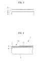
FIG. 3] FIG. 3 is a cross-sectional view showing part of a process of manufacturing the aircraft window member shown inFIG. 2 . - [
FIG. 4] FIG. 4 is a partial cross-sectional view showing an edge portion of an aircraft window member according to a second embodiment of the present invention. -
- 1,
- 1': aircraft window member
- 3:
- window main body
- 5:
- film
- 7:
- conductive mesh
- 9:
- adhesive layer
- 11:
- protective layer
- 13:
- exposed region
- Embodiments of the present invention will be described below with reference to the drawings.
- A first embodiment of the present invention will be described below with reference to
FIGS. 1 to 3 .
FIG. 1 shows an aircraft window member used for a cabin window, for example. Note that anaircraft window member 1 shown inFIG. 1 is flat, but it may be curved depending on the position at which it is installed.
Theaircraft window member 1 includes a windowmain body 3 serving as a base, afilm 5 attached to the windowmain body 3, and aconductive mesh 7 formed on thefilm 5. With theconductive mesh 7, theaircraft window member 1 has electromagnetic-wave shielding properties and also has optical transparency to ensure visibility. For example, the transmittance for visible light is about 90%. -
FIG. 2 is a partial cross-sectional view showing an edge portion of theaircraft window member 1.
As shown inFIG. 2 , thefilm 5 and theconductive mesh 7 are laminated in this order on the windowmain body 3, with anadhesive layer 9 therebetween.
The windowmain body 3 is made of acrylic resin, more specifically, polymethyl methacrylate resin (PMMA).
Thefilm 5 is made of acrylic resin, more specifically, polymethyl methacrylate resin (PMMA). In short, the same material as for the windowmain body 3 is used for thefilm 5. The thickness of thefilm 5 is 125 µm, for example.
Theconductive mesh 7 is formed in a lattice. A preferable conductive material therefor is metal, and copper is used in this embodiment. The line width of theconductive mesh 7 is about 10 µm, the thickness thereof is about 10 µm, and the pitch thereof is about 300 µm. Such a line width, thickness, and pitch achieve both of electromagnetic-wave shielding properties and visibility.
Theadhesive layer 9 is made of urethane adhesive. Film-like polyurethane is used as the urethane adhesive. After bonding, theadhesive layer 9 flows into the space between thefilm 5 and the conductive mesh and directly contacts the conductive material (copper) of theconductive mesh 7 to cover the region therearound. - Next, a method of manufacturing the
aircraft window member 1 having the above-described structure will be described.
First, a copper thin film is laminated on one face of thefilm 5 by a plating method, for example. The thickness of the copper thin film is 10 µm, for example. Then, a resist film is formed on the surface of the copper thin film. Next, the resist film is exposed to light with a resist pattern and is then developed to form a mesh-shaped mask on the surface of the copper thin film. In this state, the copper is etched by using etchant and then the resist pattern is removed, thereby forming the mesh-shapedconductive mesh 7. In this way, thefilm 5 having theconductive mesh 7 is obtained as indicated byreference numerals FIG. 3 .
After theadhesive layer 9, which is made of sheet-like urethane adhesive, is provided on the windowmain body 3, thefilm 5 is attached such that theconductive mesh 7 faces the windowmain body 3.
Next, heat treatment is applied by using an autoclave, thereby hardening theadhesive layer 9 to fix thefilm 5 to the windowmain body 3. The treatment conditions using the autoclave are set as follows: the temperature is 85°C to 95°C, the pressure is 1.03 MPa, and the treatment time is 1 hour.
Theaircraft window member 1 is obtained after being taken out from the autoclave and cooled.
Theaircraft window member 1, manufactured as described above, is then fitted into a window frame or the like, thereby obtaining an aircraft window assembly. - According to the
aircraft window member 1 of this embodiment, the following advantages are obtained.
Theaircraft window member 1 can be simply manufactured just by attaching thefilm 5 on which theconductive mesh 7 is formed to the windowmain body 3. Even when the windowmain body 3 has a curved face, since thefilm 5 on which theconductive mesh 7 is formed has flexibility, thefilm 5 can be easily attached to the windowmain body 3.
Since the windowmain body 3 and thefilm 5 are made of acrylic resin to have an equivalent thermal expansion coefficient, hardly any wrinkles occur on thefilm 5 even when they are heated by the autoclave during manufacturing and cooled thereafter.
Although theaircraft window member 1 is exposed to a large change in temperature during the operation of the aircraft, since there is no difference in thermal expansion coefficient between the windowmain body 3 and thefilm 5, peeling of the film almost never occurs, thus improving the durability.
Since urethane adhesive is used as theadhesive layer 9, it is possible to firmly bond the windowmain body 3 and thefilm 5, which are made of acrylic resin.
Since urethane adhesive does not include plasticizer, unlike polyvinyl butyral (PVB), even when it directly contacts the copper of theconductive mesh 7, a reaction does not occur and there is no adverse influence on the optical transparency of the window member. - Next, a second embodiment of the present invention will be described with reference to
FIG. 4 .
FIG. 4 is a partial cross-sectional view showing an edge portion of an aircraft window member 1' according to this embodiment.
In this embodiment, unlike the first embodiment, when thefilm 5 on which theconductive mesh 7 is formed is attached to the windowmain body 3, theconductive mesh 7 faces upward inFIG. 4 , instead of facing the windowmain body 3. Therefore, the windowmain body 3, theadhesive layer 9, thefilm 5, and theconductive mesh 7 are laminated in this order from the bottom inFIG. 4 . Since the materials and the shapes of the windowmain body 3, theadhesive layer 9, thefilm 5, and theconductive mesh 7 are the same as those in the first embodiment, a description thereof will be omitted. - A
protective layer 11 for protecting the conductive mesh is laminated on theconductive mesh 7. A film made of acrylic resin is used as theprotective layer 11. Theconductive mesh 7 and theprotective layer 11 are bonded by polyvinyl acetate adhesive.
An exposedregion 13 which is not covered with theprotective layer 11 is provided at an edge portion of theconductive mesh 7. The exposedregion 13 is used to obtain an external electrical connection when theaircraft window member 1 is fitted into a window frame to form a window assembly. - The aircraft window member 1' having the above-described structure is manufactured as follows.
Since a process of forming theconductive mesh 7 on thefilm 5 is the same as that in the first embodiment, a description thereof will be omitted.
Theprotective layer 11 is attached to theconductive mesh 7 formed on thefilm 5.
Thefilm 5 on which theconductive mesh 7 is formed is attached to the windowmain body 3. At this time, with regard to the windowmain body 3 on which the sheet-likeadhesive layer 9 is placed, thefilm 5 is brought into contact with theadhesive layer 9, with theconductive mesh 7 facing upward inFIG. 4 instead of facing the windowmain body 3.
As in the first embodiment, theadhesive layer 9 is thermally-hardened by the autoclave and cooled, thereby obtaining the aircraft window member 1'.
The aircraft window member 1' thus manufactured is then fitted into a window frame or the like, thereby obtaining an aircraft window assembly. - According to the aircraft window member 1' of this embodiment, the following advantages are obtained in addition to the advantages obtained in the first embodiment.
Since the exposedregion 13, which is not covered with theprotective layer 11, is provided at the edge portion of theconductive mesh 7 when theprotective layer 11 is laminated on theconductive mesh 7, the exposed region can be used for an electrical connection. Therefore, when the aircraft window member 1' is fitted into a window frame to form an aircraft window assembly, it is possible to obtain an external electrical connection to reliably shield electromagnetic waves. - In each of the embodiments described above, copper is used as the material of the
conductive mesh 7. However, the present invention is not limited to the use of copper. For example, gold, silver, aluminum, nickel, titanium, or tin may be used.
Claims (9)
- An aircraft window member comprising:a film made of acrylic resin;a conductive mesh which is formed on the film and in which a conductive material is formed in a mesh shape so as to have optical transparency for ensuring visibility and to have electromagnetic-wave shielding properties; anda window main body which is made of acrylic resin and to which the film on which the conductive mesh is formed is attached.
- An aircraft window member according to claim 1, wherein:an adhesive layer is formed between the film on which the conductive mesh is formed and the window main body; andthe adhesive layer is made of urethane adhesive.
- An aircraft window member according to claim 2, wherein the conductive mesh formed on the film is located between the film and the window main body.
- An aircraft window member according to claim 1 or 2, wherein:the conductive mesh is located above the window main body with the film therebetween; anda protective layer is formed on the conductive mesh in such a manner as to provide an exposed region used for an electrical connection at an edge portion of the conductive mesh.
- An aircraft window assembly comprising:an aircraft window member according to any of claims 1 to 4; anda window frame which holds the aircraft window member.
- An aircraft-window-member manufacturing method comprising attaching a film that is made of acrylic resin and that holds a conductive mesh in which a conductive material is formed in a mesh shape so as to have optical transparency for ensuring visibility and to have electromagnetic-wave shielding properties, to a window main body made of acrylic resin.
- An aircraft-window-member manufacturing method according to claim 6, wherein the film is attached to the window main body after an adhesive layer made of urethane adhesive is provided on the window main body.
- An aircraft-window-member manufacturing method according to claim 7, wherein the film is attached to the window main body so as to locate the conductive mesh between the film and the window main body.
- An aircraft-window-member manufacturing method according to claim 6 or 7, wherein:the film is attached to the window main body so as to locate the conductive mesh above the window main body with the film therebetween; anda protective layer is formed on the conductive mesh in such a manner as to provide an exposed region used for an electrical connection at an edge portion of the conductive mesh.
Applications Claiming Priority (2)
| Application Number | Priority Date | Filing Date | Title |
|---|---|---|---|
| JP2007037858A JP4969268B2 (en) | 2007-02-19 | 2007-02-19 | Aircraft window material and method of manufacturing the same |
| PCT/JP2008/052676 WO2008102737A1 (en) | 2007-02-19 | 2008-02-18 | Aircraft window member, its manufacturing method, and aircraft window assembly |
Publications (3)
| Publication Number | Publication Date |
|---|---|
| EP2123554A1 true EP2123554A1 (en) | 2009-11-25 |
| EP2123554A4 EP2123554A4 (en) | 2013-02-20 |
| EP2123554B1 EP2123554B1 (en) | 2014-04-16 |
Family
ID=39710014
Family Applications (1)
| Application Number | Title | Priority Date | Filing Date |
|---|---|---|---|
| EP20080711500 Not-in-force EP2123554B1 (en) | 2007-02-19 | 2008-02-18 | Aircraft window member, its manufacturing method, and aircraft window assembly |
Country Status (8)
| Country | Link |
|---|---|
| US (1) | US9156539B2 (en) |
| EP (1) | EP2123554B1 (en) |
| JP (1) | JP4969268B2 (en) |
| CN (1) | CN101610948B (en) |
| BR (1) | BRPI0808019B1 (en) |
| CA (1) | CA2678099C (en) |
| RU (1) | RU2409500C1 (en) |
| WO (1) | WO2008102737A1 (en) |
Cited By (2)
| Publication number | Priority date | Publication date | Assignee | Title |
|---|---|---|---|---|
| WO2013013906A1 (en) * | 2011-07-28 | 2013-01-31 | Lamiflex S.P.A. | Cladding element for providing shielding against electromagnetic radiation |
| EP2462791B1 (en) * | 2009-08-03 | 2019-11-06 | 3M Innovative Properties Company | Process for forming optically clear conductive metal or metal alloy thin films and films made therefrom |
Families Citing this family (17)
| Publication number | Priority date | Publication date | Assignee | Title |
|---|---|---|---|---|
| JP5219970B2 (en) * | 2009-09-03 | 2013-06-26 | グンゼ株式会社 | Electromagnetic wave shielding material and manufacturing method thereof |
| JP5492647B2 (en) | 2010-04-19 | 2014-05-14 | 三菱航空機株式会社 | Aircraft cockpit window with electromagnetic shield, aircraft |
| US9302452B2 (en) * | 2012-03-02 | 2016-04-05 | Ppg Industries Ohio, Inc. | Transparent laminates comprising inkjet printed conductive lines and methods of forming the same |
| CN103811105B (en) * | 2012-11-09 | 2016-11-16 | 深圳欧菲光科技股份有限公司 | Transparent conductive body and preparation method thereof |
| US9510456B2 (en) | 2012-11-09 | 2016-11-29 | Shenzhen O-Film Tech Co., Ltd. | Transparent conductor and preparation method thereof |
| US9969483B2 (en) | 2013-03-06 | 2018-05-15 | Bombardier Inc. | Aircraft floor incorporating a ground plane |
| US9626024B1 (en) | 2014-03-24 | 2017-04-18 | Amazon Technologies, Inc. | Composite cover assembly for electronic devices |
| US20160113161A1 (en) * | 2014-10-17 | 2016-04-21 | Laird Technologies, Inc. | Electromagnetic interference (emi) shields including see-through portions |
| JP6350355B2 (en) * | 2015-03-25 | 2018-07-04 | 三菱電機株式会社 | Optical window structure and optical device having optical window structure |
| DE102015110165B4 (en) * | 2015-06-24 | 2017-03-02 | Airbus Operations Gmbh | Skin panel window unit for an aircraft |
| US9497894B1 (en) * | 2015-07-22 | 2016-11-15 | John Gordon Ramsey | Low impedance radiofrequency shielded window |
| JP2017056862A (en) * | 2015-09-17 | 2017-03-23 | 日東電工株式会社 | Functional film for aircraft window, aircraft window structure, and aircraft window functionalization method |
| US9986669B2 (en) | 2015-11-25 | 2018-05-29 | Ppg Industries Ohio, Inc. | Transparency including conductive mesh including a closed shape having at least one curved side |
| US20190255789A1 (en) * | 2018-02-22 | 2019-08-22 | Ronald L. Meline | Transparency repair system |
| US11446986B1 (en) | 2018-08-14 | 2022-09-20 | Apple Inc. | Reinforced vehicle window |
| US11745702B2 (en) | 2018-12-11 | 2023-09-05 | Ppg Industries Ohio, Inc. | Coating including electrically conductive lines directly on electrically conductive layer |
| US11632884B2 (en) * | 2021-05-31 | 2023-04-18 | Nano And Advanced Materials Institute Limited | Transparent EMI shielding film and production method for the same |
Family Cites Families (50)
| Publication number | Priority date | Publication date | Assignee | Title |
|---|---|---|---|---|
| USRE25202E (en) * | 1962-07-17 | Process for forming of stretched sheet material | ||
| US2464826A (en) * | 1943-12-30 | 1949-03-22 | Rohm & Haas | Acrylic resin laminations |
| US3238909A (en) * | 1964-06-15 | 1966-03-08 | Reynolds Metals Co | Distortion correction system |
| DE1497703B2 (en) * | 1966-03-04 | 1976-12-30 | Ernst Knoll Geoplastischer Verlag, 4973 Vlotho | Process for the production of colored, rollable, relief maps from plastic film |
| US3431348A (en) * | 1966-05-06 | 1969-03-04 | Tech Wire Prod Inc | Electromagnetic shield and viewing laminate |
| US3631580A (en) * | 1969-09-15 | 1972-01-04 | William M Swartz | Method of making plastic articles |
| IT1027377B (en) * | 1974-04-01 | 1978-11-20 | Ppg Industries Inc | LAMINATED WINDSHIELD FOR AIRCRAFT |
| US3946672A (en) * | 1974-08-13 | 1976-03-30 | Thiokol Corporation | Rocket propelled projectile |
| SU685548A1 (en) * | 1977-06-20 | 1979-09-15 | Дальневосточный государственный университет | Scuttle |
| US4361527A (en) * | 1981-10-21 | 1982-11-30 | Ppg Industries, Inc. | Method of forming stretched acrylic sheets |
| US4504341A (en) * | 1982-09-20 | 1985-03-12 | Ppg Industries, Inc. | Fabricating shaped laminated transparencies |
| ES8606126A1 (en) * | 1984-04-04 | 1986-04-01 | Pilkington Brothers Plc | Impact resistant laminate. |
| US4721636A (en) * | 1984-11-01 | 1988-01-26 | Southwall Technologies, Inc. | Multiple pane glass unit with electrically conductive transparent film for use as radiation shield |
| US4920254A (en) * | 1988-02-22 | 1990-04-24 | Sierracin Corporation | Electrically conductive window and a method for its manufacture |
| FR2639878B1 (en) * | 1988-12-01 | 1991-01-11 | Cebal | PROCESS FOR DECORATING A BLANK TO BE CONFORMED, USE OF THIS PROCESS AND PRODUCTS OBTAINED |
| JPH0746222B2 (en) * | 1989-09-12 | 1995-05-17 | 東洋製罐株式会社 | Pre-printing method for taper drawing material |
| US5194985A (en) * | 1990-06-29 | 1993-03-16 | Amorphous Materials, Inc. | Protected airborne window for infrared radiation and method of making same |
| US5165965A (en) * | 1990-12-28 | 1992-11-24 | Reynolds Metals Company | Method for providing predistored images on shrinkable film |
| RU2009947C1 (en) * | 1991-06-28 | 1994-03-30 | Грисюк Юрий Александрович | Port-hole of submarine vessel |
| US5370921A (en) * | 1991-07-11 | 1994-12-06 | The Dexter Corporation | Lightning strike composite and process |
| GB9123643D0 (en) * | 1991-11-07 | 1992-07-22 | Triplex Aircraft And Special P | Windows |
| US5670742A (en) * | 1994-02-04 | 1997-09-23 | Threshold Technologies, Inc. | EMI protected aircraft |
| GB9419513D0 (en) * | 1994-09-28 | 1994-11-16 | Enviromed Plc | Electrochemical oxygen sensor |
| US5776612A (en) * | 1996-02-21 | 1998-07-07 | Exotic Materials Inc. | Window that transmits light energy and selectively absorbs microwave energy |
| CA2214594C (en) | 1996-11-05 | 2002-11-26 | Robert M. Hunia | Improved aircraft transparency |
| JPH10178296A (en) | 1996-12-18 | 1998-06-30 | Sekisui Chem Co Ltd | Electromagnetic shielding plate and method of manufacturing electromagnetic shielding plate |
| US6028699A (en) * | 1997-01-13 | 2000-02-22 | Exotic Electrooptics | Electromagnetically shielded window, sensor system using the window, and method of manufacture |
| JP3243789B2 (en) * | 1997-03-31 | 2002-01-07 | 日本板硝子株式会社 | Radio wave absorbing panel |
| JP4063945B2 (en) * | 1998-03-19 | 2008-03-19 | リンテック株式会社 | Radio wave shielding material |
| JP3653989B2 (en) | 1998-06-09 | 2005-06-02 | 豊田合成株式会社 | Electromagnetic shield grounding structure |
| JP2000034451A (en) | 1998-07-16 | 2000-02-02 | Tomoegawa Paper Co Ltd | Infrared cutoff film |
| KR100654114B1 (en) * | 1998-10-30 | 2006-12-05 | 스미또모 가가꾸 가부시끼가이샤 | Electromagnetic wave shield plate |
| JP2000174486A (en) | 1998-12-04 | 2000-06-23 | Sumitomo Rubber Ind Ltd | Light transmitting electromagnetic wave shielding film and method of manufacturing light transmitting electromagnetic wave shielding panel |
| US6544634B1 (en) * | 1999-03-19 | 2003-04-08 | Pinnacle Products Group, Ltd. | Graphic image fusion |
| FR2793106B1 (en) * | 1999-04-28 | 2001-06-22 | Saint Gobain Vitrage | MULTIPLE INSULATING WINDOWS, ESPECIALLY AIRPLANE WINDOWS, WITH ELECTROMAGNETIC SHIELDING |
| JP2001189589A (en) * | 1999-12-27 | 2001-07-10 | Bridgestone Corp | Electromagnetic shielding film, electromagnetic shielding translucent window material, and display |
| US6560050B2 (en) | 2001-06-12 | 2003-05-06 | Lockheed Martin Corporation | Optical segmented RF signature managed window |
| JP3572300B2 (en) * | 2001-08-03 | 2004-09-29 | 三菱重工業株式会社 | Aircraft window made of synthetic resin with hard film |
| JPWO2003045126A1 (en) | 2001-11-20 | 2005-04-07 | 株式会社ブリヂストン | Electromagnetic shielding light transmissive window material and method for manufacturing the same |
| JP2004117545A (en) * | 2002-09-24 | 2004-04-15 | Mitsui Chemicals Inc | Method for manufacturing display filter |
| JP2004140283A (en) * | 2002-10-21 | 2004-05-13 | Nisshinbo Ind Inc | Thin electromagnetic wave shield laminate for display and method of manufacturing the same |
| JP2004146536A (en) | 2002-10-23 | 2004-05-20 | Mitsui Chemicals Inc | Filter for display |
| US20040229607A1 (en) * | 2003-05-12 | 2004-11-18 | La Chapelle Michael De | Wireless communication inside shielded envelope |
| JP4370139B2 (en) * | 2003-09-30 | 2009-11-25 | 三菱重工業株式会社 | Method for manufacturing window having radio stealth and / or electromagnetic wave shielding and window material having radio stealth and / or electromagnetic wave shielding |
| JP4148108B2 (en) | 2003-11-10 | 2008-09-10 | 株式会社ブリヂストン | Electromagnetic shielding light transmissive window material and method for manufacturing the same |
| EP1696719A4 (en) * | 2003-11-14 | 2008-10-29 | Bridgestone Corp | Electromagnetic-shielding light-transmitting window material and method for producing same |
| WO2005086557A1 (en) * | 2004-03-03 | 2005-09-15 | Bridgestone Corporation | Electromagnetic shielding light transmitting window material, display panel and method for manufacturing solar cell module |
| DE102004025375B4 (en) * | 2004-05-24 | 2010-01-28 | Airbus Deutschland Gmbh | Window frame for aircraft |
| JP2005277438A (en) * | 2005-05-24 | 2005-10-06 | Mitsui Chemicals Inc | Manufacturing method for filter used for display unit |
| US7350753B2 (en) * | 2005-07-21 | 2008-04-01 | Row 44, Inc. | RF shielding for aircraft windows |
-
2007
- 2007-02-19 JP JP2007037858A patent/JP4969268B2/en not_active Expired - Fee Related
-
2008
- 2008-02-18 EP EP20080711500 patent/EP2123554B1/en not_active Not-in-force
- 2008-02-18 US US12/525,912 patent/US9156539B2/en not_active Expired - Fee Related
- 2008-02-18 CA CA 2678099 patent/CA2678099C/en not_active Expired - Fee Related
- 2008-02-18 BR BRPI0808019A patent/BRPI0808019B1/en not_active IP Right Cessation
- 2008-02-18 CN CN2008800051063A patent/CN101610948B/en not_active Expired - Fee Related
- 2008-02-18 RU RU2009129221A patent/RU2409500C1/en not_active IP Right Cessation
- 2008-02-18 WO PCT/JP2008/052676 patent/WO2008102737A1/en not_active Ceased
Cited By (2)
| Publication number | Priority date | Publication date | Assignee | Title |
|---|---|---|---|---|
| EP2462791B1 (en) * | 2009-08-03 | 2019-11-06 | 3M Innovative Properties Company | Process for forming optically clear conductive metal or metal alloy thin films and films made therefrom |
| WO2013013906A1 (en) * | 2011-07-28 | 2013-01-31 | Lamiflex S.P.A. | Cladding element for providing shielding against electromagnetic radiation |
Also Published As
| Publication number | Publication date |
|---|---|
| EP2123554A4 (en) | 2013-02-20 |
| BRPI0808019A8 (en) | 2016-03-08 |
| RU2409500C1 (en) | 2011-01-20 |
| EP2123554B1 (en) | 2014-04-16 |
| CA2678099A1 (en) | 2008-08-28 |
| CN101610948A (en) | 2009-12-23 |
| JP4969268B2 (en) | 2012-07-04 |
| WO2008102737A1 (en) | 2008-08-28 |
| BRPI0808019A2 (en) | 2014-06-17 |
| US9156539B2 (en) | 2015-10-13 |
| US20100304069A1 (en) | 2010-12-02 |
| CN101610948B (en) | 2013-05-15 |
| CA2678099C (en) | 2012-10-30 |
| JP2008201206A (en) | 2008-09-04 |
| BRPI0808019B1 (en) | 2020-04-28 |
Similar Documents
| Publication | Publication Date | Title |
|---|---|---|
| EP2123554B1 (en) | Aircraft window member, its manufacturing method, and aircraft window assembly | |
| CN102574572B (en) | Cockpit windows of aircraft with electromagnetic shielding, aircraft | |
| US10682957B2 (en) | Laminated glass for vehicle with inner mirror | |
| US8153237B2 (en) | Laminated glass pane having an integrated retaining element | |
| EP2570342B1 (en) | Aircraft window | |
| EP1196018A1 (en) | Method of forming electrode section on inner surface of transparent electromagnetic wave shielding plate and transparent electromagnetic wave shielding plate formed thereby | |
| US7722948B2 (en) | Laminated Glazing | |
| EP3689989A1 (en) | Method for producing vehicular structure and method for producing protective film-attached transparent substrate | |
| WO2013105178A1 (en) | Aircraft window, aircraft, and assembly method for aircraft window | |
| JP2017056862A (en) | Functional film for aircraft window, aircraft window structure, and aircraft window functionalization method | |
| US10974645B2 (en) | Vehicle pane with a covered lighting device | |
| JPWO2018173738A1 (en) | Vehicle front windows and vehicle articles | |
| US20250089161A1 (en) | Ultra-thin laminated glass assembly with electric circuitry | |
| JP2012116481A (en) | Window member for aircraft and method for manufacturing the same | |
| CN209746530U (en) | Touch display device with narrow frame | |
| EP4247124A1 (en) | Wiring board, and method for manufacturing wiring board | |
| EP3882059A1 (en) | Glass plate module and production method for glass plate module | |
| JP4154717B2 (en) | Electromagnetic wave cut filter | |
| JP2002319788A (en) | Electromagnetic shielding sheet and electromagnetic shield structuring method | |
| JP2016084254A (en) | Laminated glass manufacturing method |
Legal Events
| Date | Code | Title | Description |
|---|---|---|---|
| PUAI | Public reference made under article 153(3) epc to a published international application that has entered the european phase |
Free format text: ORIGINAL CODE: 0009012 |
|
| 17P | Request for examination filed |
Effective date: 20090804 |
|
| AK | Designated contracting states |
Kind code of ref document: A1 Designated state(s): AT BE BG CH CY CZ DE DK EE ES FI FR GB GR HR HU IE IS IT LI LT LU LV MC MT NL NO PL PT RO SE SI SK TR |
|
| DAX | Request for extension of the european patent (deleted) | ||
| RAP1 | Party data changed (applicant data changed or rights of an application transferred) |
Owner name: MITSUBISHI HEAVY INDUSTRIES, LTD. |
|
| A4 | Supplementary search report drawn up and despatched |
Effective date: 20130117 |
|
| RIC1 | Information provided on ipc code assigned before grant |
Ipc: B64C 1/14 20060101AFI20130111BHEP Ipc: H05K 9/00 20060101ALI20130111BHEP |
|
| GRAP | Despatch of communication of intention to grant a patent |
Free format text: ORIGINAL CODE: EPIDOSNIGR1 |
|
| INTG | Intention to grant announced |
Effective date: 20130910 |
|
| GRAS | Grant fee paid |
Free format text: ORIGINAL CODE: EPIDOSNIGR3 |
|
| GRAA | (expected) grant |
Free format text: ORIGINAL CODE: 0009210 |
|
| AK | Designated contracting states |
Kind code of ref document: B1 Designated state(s): AT BE BG CH CY CZ DE DK EE ES FI FR GB GR HR HU IE IS IT LI LT LU LV MC MT NL NO PL PT RO SE SI SK TR |
|
| REG | Reference to a national code |
Ref country code: GB Ref legal event code: FG4D |
|
| REG | Reference to a national code |
Ref country code: CH Ref legal event code: EP |
|
| REG | Reference to a national code |
Ref country code: AT Ref legal event code: REF Ref document number: 662346 Country of ref document: AT Kind code of ref document: T Effective date: 20140515 |
|
| REG | Reference to a national code |
Ref country code: IE Ref legal event code: FG4D |
|
| REG | Reference to a national code |
Ref country code: DE Ref legal event code: R096 Ref document number: 602008031529 Country of ref document: DE Effective date: 20140528 |
|
| REG | Reference to a national code |
Ref country code: AT Ref legal event code: MK05 Ref document number: 662346 Country of ref document: AT Kind code of ref document: T Effective date: 20140416 |
|
| REG | Reference to a national code |
Ref country code: NL Ref legal event code: VDEP Effective date: 20140416 |
|
| REG | Reference to a national code |
Ref country code: LT Ref legal event code: MG4D |
|
| PG25 | Lapsed in a contracting state [announced via postgrant information from national office to epo] |
Ref country code: CY Free format text: LAPSE BECAUSE OF FAILURE TO SUBMIT A TRANSLATION OF THE DESCRIPTION OR TO PAY THE FEE WITHIN THE PRESCRIBED TIME-LIMIT Effective date: 20140416 Ref country code: FI Free format text: LAPSE BECAUSE OF FAILURE TO SUBMIT A TRANSLATION OF THE DESCRIPTION OR TO PAY THE FEE WITHIN THE PRESCRIBED TIME-LIMIT Effective date: 20140416 Ref country code: IS Free format text: LAPSE BECAUSE OF FAILURE TO SUBMIT A TRANSLATION OF THE DESCRIPTION OR TO PAY THE FEE WITHIN THE PRESCRIBED TIME-LIMIT Effective date: 20140816 Ref country code: NL Free format text: LAPSE BECAUSE OF FAILURE TO SUBMIT A TRANSLATION OF THE DESCRIPTION OR TO PAY THE FEE WITHIN THE PRESCRIBED TIME-LIMIT Effective date: 20140416 Ref country code: NO Free format text: LAPSE BECAUSE OF FAILURE TO SUBMIT A TRANSLATION OF THE DESCRIPTION OR TO PAY THE FEE WITHIN THE PRESCRIBED TIME-LIMIT Effective date: 20140716 Ref country code: GR Free format text: LAPSE BECAUSE OF FAILURE TO SUBMIT A TRANSLATION OF THE DESCRIPTION OR TO PAY THE FEE WITHIN THE PRESCRIBED TIME-LIMIT Effective date: 20140717 Ref country code: BG Free format text: LAPSE BECAUSE OF FAILURE TO SUBMIT A TRANSLATION OF THE DESCRIPTION OR TO PAY THE FEE WITHIN THE PRESCRIBED TIME-LIMIT Effective date: 20140716 Ref country code: LT Free format text: LAPSE BECAUSE OF FAILURE TO SUBMIT A TRANSLATION OF THE DESCRIPTION OR TO PAY THE FEE WITHIN THE PRESCRIBED TIME-LIMIT Effective date: 20140416 |
|
| PG25 | Lapsed in a contracting state [announced via postgrant information from national office to epo] |
Ref country code: ES Free format text: LAPSE BECAUSE OF FAILURE TO SUBMIT A TRANSLATION OF THE DESCRIPTION OR TO PAY THE FEE WITHIN THE PRESCRIBED TIME-LIMIT Effective date: 20140416 Ref country code: AT Free format text: LAPSE BECAUSE OF FAILURE TO SUBMIT A TRANSLATION OF THE DESCRIPTION OR TO PAY THE FEE WITHIN THE PRESCRIBED TIME-LIMIT Effective date: 20140416 Ref country code: HR Free format text: LAPSE BECAUSE OF FAILURE TO SUBMIT A TRANSLATION OF THE DESCRIPTION OR TO PAY THE FEE WITHIN THE PRESCRIBED TIME-LIMIT Effective date: 20140416 Ref country code: SE Free format text: LAPSE BECAUSE OF FAILURE TO SUBMIT A TRANSLATION OF THE DESCRIPTION OR TO PAY THE FEE WITHIN THE PRESCRIBED TIME-LIMIT Effective date: 20140416 Ref country code: PL Free format text: LAPSE BECAUSE OF FAILURE TO SUBMIT A TRANSLATION OF THE DESCRIPTION OR TO PAY THE FEE WITHIN THE PRESCRIBED TIME-LIMIT Effective date: 20140416 Ref country code: LV Free format text: LAPSE BECAUSE OF FAILURE TO SUBMIT A TRANSLATION OF THE DESCRIPTION OR TO PAY THE FEE WITHIN THE PRESCRIBED TIME-LIMIT Effective date: 20140416 |
|
| PG25 | Lapsed in a contracting state [announced via postgrant information from national office to epo] |
Ref country code: PT Free format text: LAPSE BECAUSE OF FAILURE TO SUBMIT A TRANSLATION OF THE DESCRIPTION OR TO PAY THE FEE WITHIN THE PRESCRIBED TIME-LIMIT Effective date: 20140818 |
|
| REG | Reference to a national code |
Ref country code: DE Ref legal event code: R097 Ref document number: 602008031529 Country of ref document: DE |
|
| PG25 | Lapsed in a contracting state [announced via postgrant information from national office to epo] |
Ref country code: SK Free format text: LAPSE BECAUSE OF FAILURE TO SUBMIT A TRANSLATION OF THE DESCRIPTION OR TO PAY THE FEE WITHIN THE PRESCRIBED TIME-LIMIT Effective date: 20140416 Ref country code: RO Free format text: LAPSE BECAUSE OF FAILURE TO SUBMIT A TRANSLATION OF THE DESCRIPTION OR TO PAY THE FEE WITHIN THE PRESCRIBED TIME-LIMIT Effective date: 20140416 Ref country code: CZ Free format text: LAPSE BECAUSE OF FAILURE TO SUBMIT A TRANSLATION OF THE DESCRIPTION OR TO PAY THE FEE WITHIN THE PRESCRIBED TIME-LIMIT Effective date: 20140416 Ref country code: BE Free format text: LAPSE BECAUSE OF FAILURE TO SUBMIT A TRANSLATION OF THE DESCRIPTION OR TO PAY THE FEE WITHIN THE PRESCRIBED TIME-LIMIT Effective date: 20140416 Ref country code: EE Free format text: LAPSE BECAUSE OF FAILURE TO SUBMIT A TRANSLATION OF THE DESCRIPTION OR TO PAY THE FEE WITHIN THE PRESCRIBED TIME-LIMIT Effective date: 20140416 Ref country code: DK Free format text: LAPSE BECAUSE OF FAILURE TO SUBMIT A TRANSLATION OF THE DESCRIPTION OR TO PAY THE FEE WITHIN THE PRESCRIBED TIME-LIMIT Effective date: 20140416 |
|
| PLBE | No opposition filed within time limit |
Free format text: ORIGINAL CODE: 0009261 |
|
| STAA | Information on the status of an ep patent application or granted ep patent |
Free format text: STATUS: NO OPPOSITION FILED WITHIN TIME LIMIT |
|
| 26N | No opposition filed |
Effective date: 20150119 |
|
| PG25 | Lapsed in a contracting state [announced via postgrant information from national office to epo] |
Ref country code: IT Free format text: LAPSE BECAUSE OF FAILURE TO SUBMIT A TRANSLATION OF THE DESCRIPTION OR TO PAY THE FEE WITHIN THE PRESCRIBED TIME-LIMIT Effective date: 20140416 |
|
| REG | Reference to a national code |
Ref country code: DE Ref legal event code: R097 Ref document number: 602008031529 Country of ref document: DE Effective date: 20150119 |
|
| PG25 | Lapsed in a contracting state [announced via postgrant information from national office to epo] |
Ref country code: SI Free format text: LAPSE BECAUSE OF FAILURE TO SUBMIT A TRANSLATION OF THE DESCRIPTION OR TO PAY THE FEE WITHIN THE PRESCRIBED TIME-LIMIT Effective date: 20140416 |
|
| PG25 | Lapsed in a contracting state [announced via postgrant information from national office to epo] |
Ref country code: LU Free format text: LAPSE BECAUSE OF FAILURE TO SUBMIT A TRANSLATION OF THE DESCRIPTION OR TO PAY THE FEE WITHIN THE PRESCRIBED TIME-LIMIT Effective date: 20150218 |
|
| REG | Reference to a national code |
Ref country code: CH Ref legal event code: PL |
|
| GBPC | Gb: european patent ceased through non-payment of renewal fee |
Effective date: 20150218 |
|
| PG25 | Lapsed in a contracting state [announced via postgrant information from national office to epo] |
Ref country code: LI Free format text: LAPSE BECAUSE OF NON-PAYMENT OF DUE FEES Effective date: 20150228 Ref country code: CH Free format text: LAPSE BECAUSE OF NON-PAYMENT OF DUE FEES Effective date: 20150228 Ref country code: MC Free format text: LAPSE BECAUSE OF FAILURE TO SUBMIT A TRANSLATION OF THE DESCRIPTION OR TO PAY THE FEE WITHIN THE PRESCRIBED TIME-LIMIT Effective date: 20140416 |
|
| REG | Reference to a national code |
Ref country code: IE Ref legal event code: MM4A |
|
| REG | Reference to a national code |
Ref country code: FR Ref legal event code: PLFP Year of fee payment: 9 |
|
| PG25 | Lapsed in a contracting state [announced via postgrant information from national office to epo] |
Ref country code: IE Free format text: LAPSE BECAUSE OF NON-PAYMENT OF DUE FEES Effective date: 20150218 Ref country code: GB Free format text: LAPSE BECAUSE OF NON-PAYMENT OF DUE FEES Effective date: 20150218 |
|
| PG25 | Lapsed in a contracting state [announced via postgrant information from national office to epo] |
Ref country code: MT Free format text: LAPSE BECAUSE OF FAILURE TO SUBMIT A TRANSLATION OF THE DESCRIPTION OR TO PAY THE FEE WITHIN THE PRESCRIBED TIME-LIMIT Effective date: 20140416 |
|
| REG | Reference to a national code |
Ref country code: FR Ref legal event code: PLFP Year of fee payment: 10 |
|
| PG25 | Lapsed in a contracting state [announced via postgrant information from national office to epo] |
Ref country code: HU Free format text: LAPSE BECAUSE OF FAILURE TO SUBMIT A TRANSLATION OF THE DESCRIPTION OR TO PAY THE FEE WITHIN THE PRESCRIBED TIME-LIMIT; INVALID AB INITIO Effective date: 20080218 |
|
| PG25 | Lapsed in a contracting state [announced via postgrant information from national office to epo] |
Ref country code: TR Free format text: LAPSE BECAUSE OF FAILURE TO SUBMIT A TRANSLATION OF THE DESCRIPTION OR TO PAY THE FEE WITHIN THE PRESCRIBED TIME-LIMIT Effective date: 20140416 |
|
| REG | Reference to a national code |
Ref country code: FR Ref legal event code: PLFP Year of fee payment: 11 |
|
| PGFP | Annual fee paid to national office [announced via postgrant information from national office to epo] |
Ref country code: DE Payment date: 20211230 Year of fee payment: 15 |
|
| PGFP | Annual fee paid to national office [announced via postgrant information from national office to epo] |
Ref country code: FR Payment date: 20220118 Year of fee payment: 15 |
|
| REG | Reference to a national code |
Ref country code: DE Ref legal event code: R119 Ref document number: 602008031529 Country of ref document: DE |
|
| PG25 | Lapsed in a contracting state [announced via postgrant information from national office to epo] |
Ref country code: FR Free format text: LAPSE BECAUSE OF NON-PAYMENT OF DUE FEES Effective date: 20230228 Ref country code: DE Free format text: LAPSE BECAUSE OF NON-PAYMENT OF DUE FEES Effective date: 20230901 |