EP2123415A1 - Oil removing jig and molded article producing method using the same - Google Patents
Oil removing jig and molded article producing method using the same Download PDFInfo
- Publication number
- EP2123415A1 EP2123415A1 EP08711358A EP08711358A EP2123415A1 EP 2123415 A1 EP2123415 A1 EP 2123415A1 EP 08711358 A EP08711358 A EP 08711358A EP 08711358 A EP08711358 A EP 08711358A EP 2123415 A1 EP2123415 A1 EP 2123415A1
- Authority
- EP
- European Patent Office
- Prior art keywords
- oil
- clay
- hole
- rubber plate
- diameter
- Prior art date
- Legal status (The legal status is an assumption and is not a legal conclusion. Google has not performed a legal analysis and makes no representation as to the accuracy of the status listed.)
- Granted
Links
Images
Classifications
-
- B—PERFORMING OPERATIONS; TRANSPORTING
- B28—WORKING CEMENT, CLAY, OR STONE
- B28B—SHAPING CLAY OR OTHER CERAMIC COMPOSITIONS; SHAPING SLAG; SHAPING MIXTURES CONTAINING CEMENTITIOUS MATERIAL, e.g. PLASTER
- B28B17/00—Details of, or accessories for, apparatus for shaping the material; Auxiliary measures taken in connection with such shaping
- B28B17/02—Conditioning the material prior to shaping
- B28B17/026—Conditioning ceramic materials
-
- B—PERFORMING OPERATIONS; TRANSPORTING
- B28—WORKING CEMENT, CLAY, OR STONE
- B28B—SHAPING CLAY OR OTHER CERAMIC COMPOSITIONS; SHAPING SLAG; SHAPING MIXTURES CONTAINING CEMENTITIOUS MATERIAL, e.g. PLASTER
- B28B3/00—Producing shaped articles from the material by using presses; Presses specially adapted therefor
- B28B3/20—Producing shaped articles from the material by using presses; Presses specially adapted therefor wherein the material is extruded
Definitions
- the present invention relates to an oil-removing jig used for removing oil applied on an outer peripheral face of cylindrical clay extruded from a kneader for the purpose of inhibiting drying prior to feeding the clay into an extrusion-forming apparatus and to a method for manufacturing a formed body using the jig.
- a material for the rubber plate 2 preferably has oil resistance where the rubber plate 2 is hardly deteriorated by the contact with the oil applied on the kneaded clay 8.
- suitable material include silicon rubber, urethane rubber, and neoprene rubber.
- a method for manufacturing a formed body of the present invention includes the steps of: passing the kneaded clay having a cylindrical shape extruded from the kneader and having the oil for inhibiting drying applied on the outer peripheral face thereof through the through-holes of the jig for removing oil of the present invention described above to remove the oil applied on the outer peripheral face of the kneaded clay, and feeding the kneaded clay into the extrusion-forming apparatus.
- the shape of the formed body manufactured by a manufacturing method of the present invention is not particularly limited as long as the shape can be obtained by extrusion forming and suitable for manufacturing, for example, a honeycomb formed body which has thin partition walls partitioning cells and is prone to have deformation.
- the kind of the oil for inhibiting drying which is removed by an oil-removing jig of the present invention is not particularly limited, and, as examples of the oil used for this kind of purpose include kerosene and machine oil (mineral oil).
- the present invention is used in order to remove oil applied on an outer peripheral face of kneaded clay having a cylindrical shape extruded from a kneader for the purpose of inhibiting drying prior to feeding the clay into an extrusion-forming apparatus and can suitably be used for manufacturing a formed body obtained by extrusion forming such as a honeycomb formed body.
Landscapes
- Engineering & Computer Science (AREA)
- Ceramic Engineering (AREA)
- Chemical & Material Sciences (AREA)
- Mechanical Engineering (AREA)
- Press-Shaping Or Shaping Using Conveyers (AREA)
- Devices For Post-Treatments, Processing, Supply, Discharge, And Other Processes (AREA)
- Extrusion Moulding Of Plastics Or The Like (AREA)
Abstract
Description
- The present invention relates to an oil-removing jig used for removing oil applied on an outer peripheral face of cylindrical clay extruded from a kneader for the purpose of inhibiting drying prior to feeding the clay into an extrusion-forming apparatus and to a method for manufacturing a formed body using the jig.
- A honeycomb-shaped structure (honeycomb structure) is widely used as a carrier for a chemical reaction apparatus such as a carrier for catalyst purifying exhaust gas from various internal combustion engines, a carrier for a deodorant catalyst, a filter for various filtration apparatuses, a heat-exchanger unit, and a carrier for reforming catalyst of a fuel cell, and the like.
Generally, such a honeycomb structure can be manufactured by subjecting kneaded clay made of ceramic raw material or the like to extrusion-forming to obtain a formed body having a predetermined honeycomb structure (honeycomb formed body), followed by drying and firing. - Generally, a kneaded clay used for forming such a honeycomb formed body can be obtained by feeding a forming raw material containing a ceramic powder as the main component into a kneader to knead the forming raw material inside a drum of the kneader with a screw with imparting shearing force to the material, and then continuously extruding the material from an opening portion at a tip of the drum to obtain a cylindrical shape.
- The kneaded clay obtained as described above is then fed into a cylinder of extrusion-forming apparatus and extrusion-formed into a predetermined honeycomb shape through a die for forming disposed on the end of outlet side of the cylinder. Here, the cylindrical clay extruded from the kneader is sometimes subjected to coating with oil such as kerosene and machine oil (mineral oil) on the outer peripheral face thereof in order to prevent drying caused before the kneaded clay is fed into an extrusion-forming apparatus.
- However, when the kneaded clay is fed into the extrusion-forming apparatus in the state that a large amount of oil is applied on the outer peripheral face of the kneaded clay, slippage is caused in a contact portion between the outer peripheral face of the kneaded clay and the inner peripheral face of the cylinder of the extrusion-forming apparatus, and thereby the extrusion speed of the outer peripheral face of the kneaded clay becomes higher than that of the central portion, which causes a problem of deformation in cells in the vicinity of the outer periphery of a honeycomb formed body obtained by extrusion-forming.
- In order to cope with such a problem, there has been taken a measure of manually wiping off the oil applied on the outer peripheral face of the kneaded clay (There has been available no prior art document relating to such a conventional technique.). However, since such a manual operation requires much labor and time, it is unsuitable for mass production, and therefore, an easier measure has been desired.
- The present invention has been made in view of such a conventional situation and aims to provide an oil-removing jig capable of easily removing oil applied on an outer peripheral face of kneaded clay having a cylindrical shape extruded from a kneader for the purpose of inhibiting drying prior to feeding the kneaded clay into an extrusion-forming apparatus and a method for manufacturing a formed body using the jig.
- In order to achieve the above aim, according to the present invention, there is provided the following oil-removing jig and method for manufacturing a formed body.
- [1] An oil-removing jig for removing oil applied on an outer peripheral face of kneaded clay having a cylindrical shape extruded from a kneader for the purpose of inhibiting drying prior to feeding the kneaded clay into an extrusion-forming apparatus, wherein the jig comprises: a tabular rubber plate having a through-hole having a
diameter 5 to 30 mm smaller than that of the kneaded clay formed therein, and two support plates each having a through-hole having a diameter 25 to 95 mm larger than that of the kneaded clay and 40 to 100 mm larger than that of the through-hole of the aforementioned rubber plate; the rubber plate being held between the two support plates and fixed in a state that centers of the through-holes coincide with one another. - [2] The jig for removing oil according to [1] wherein the rubber plate has a hardness of 40 to 60°.
- [3] The jig for removing oil according to [1] or [2], wherein the rubber plate has a thickness of 2 to 7 mm.
- [4] The jig for removing oil according to any one of [1] to [3], wherein the rubber plate is of silicon rubber, urethane rubber, or neoprene rubber.
- [5] A method for manufacturing a formed body comprising the steps of: passing the kneaded clay having a cylindrical shape extruded from the kneader and being provided with an oil for inhibiting drying applied on an outer peripheral face thereof through the through-holes of the jig for removing oil according to any one of [1] to [4] to remove the oil applied on the outer peripheral face of the kneaded clay, and feeding the kneaded clay into the extrusion-forming apparatus.
- [6] The method for forming a formed body according to [5], wherein the formed body is a honeycomb formed body.
- By the use of an oil-removing jig of the present invention, oil applied on an outer peripheral face of kneaded clay having a cylindrical shape extruded from a kneader for the purpose of inhibiting drying can easily be removed prior to feeding the kneaded clay into an extrusion-forming apparatus. In addition, according to a method for manufacturing a formed body of the present invention, after the oil applied on the outer peripheral face of the kneaded clay is removed by using the oil-removing jig, the kneaded clay is fed into an extrusion-forming apparatus, and thereby deformation due to the oil of the formed body can be inhibited easily.
-
- [
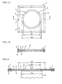
Fig. 1A ] A plan view showing an example of a structure of an oil-removing jig of the present invention. - [
Fig. 1B ] An A-A cross-sectional view ofFig. 1A . - [
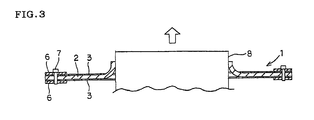
Fig. 2 ] An explanatory view showing an example of usage of an oil-removing jig of the present invention. - [
Fig. 3 ] An explanatory view showing an example of usage of an oil-removing jig of the present invention. - 1: oil-removing jig, 2: rubber plate, 3: support plate, 4: through-hole, 5: through-hole, 6: frame, 7: bolt, 8: clay
- Hereinbelow, representative embodiments of the present invention will be described specifically with referring to drawings. However, the present invention is by no means limited to the following embodiments, and it should be understood that changes, improvements, and the like of the design may be made on the basis of ordinary knowledge of a person ordinary skill in the art within the range of not deviating from the gist of the present invention.
-
Figs. 1A and 1B show an example of a structure of an oil-removing jig of the present invention.Fig. 1A is a plan view, andFig. 1B is an A-A cross-sectional view ofFig. 1A . The oil-removing jig 1 is a jig used for removing oil applied on an outer peripheral face of kneaded clay having a cylindrical shape extruded from a kneader for the purpose of inhibiting drying prior to feeding the clay into an extrusion-forming apparatus. - The oil-removing jig 1 has a
tabular rubber plate 2 having a through-hole 4 having a diameter D1 which is 5 to 30 mm smaller than that of the kneaded clay having a cylindrical shape to be subjected to oil-removing, and twosupport plates 3 each having a through-hole 5 having a diameter D2 which is 25 to 95 mm larger than that of the diameter of the kneaded clay and 40 to 100 mm larger than that of the through-hole 4 of therubber plate 2, and therubber plate 2 is held between the twosupport plates 3 and fixed in a state that the centers of the through-holes coincides with one another. In the present embodiment, thesupport plates 3 and therubber plate 2 piled up as described above are unitarily fixed by fastening with abolt 7 by means of aframe 6 in the vicinity of the outer periphery. - As shown in
Fig. 2 , when the kneaded clay having acylindrical shape 8 extruded from a kneader and having oil applied on the outer peripheral face thereof for inhibiting drying is passed through the through-hole of the oil-removing jig 1 having such a structure as described above, therubber plate 2 having a through-hole 4 having a diameter D1 smaller than the diameter D3 of theclay 8 is brought into contact with the outer peripheral face of theclay 8 in a state that a peripheral portion of the through-hole is bent as shown inFig. 3 , and theclay 8 moves in one direction in this state, thereby moderately removing the oil applied on the outer peripheral face by scraping the oil with therubber plate 2. - Incidentally, it is not necessary to completely remove the oil applied on the outer peripheral face of the
clay 8, and a little oil remaining to some extent is preferable because the kneaded clay can be inserted smoothly into the cylinder of the extrusion-forming apparatus. The oil-remaining state can be controlled by the difference between the diameter D3 of theclay 8 and the diameter D1 of the through-hole 4 of therubber plate 2, the difference between the diameter D3 of theclay 8 and the diameter D2 of the through-hole 5 of thesupport plates 3, or the difference between the diameter D1 of the through-hole 4 of therubber plate 2 and the diameter D2 of the through-hole 5 of thesupport plates 3 and can be adjusted also by the hardness, thickness, or the like of therubber plate 2. - As described above, in an oil-removing jig of the present invention, the diameter D1 of the through-
hole 4 of therubber plate 2 is made 5 to 30 mm, preferably 5 to 25 mm, and more preferably 10 to 25 smaller than the diameter D3 of the kneadedclay 8. When the difference (D3 - D1) between the diameter D3 of theclay 8 and the diameter D1 of the through-hole 4 of therubber plate 2 is less than 5 mm, the removal of the oil is prone to be insufficient, and superfluous oil remains on the outer peripheral face of the kneadedclay 8. Therefore, deformation of the formed body caused by the remaining oil cannot effectively be suppressed. On the other hand, when the difference between the diameter D3 of theclay 8 and the diameter D1 of the through-hole 4 of therubber plate 2 is more than 30 mm, theclay 8 may have difficulty in passing through the oil-removing jig 1, or oil is excessively removed to cause difficulty in allowing theclay 8 to enter the cylinder of the extrusion forming apparatus. - In addition, in an oil-removing jig of the present invention, the diameter D2 of the through-
hole 5 of thesupport plates 3 is made 25 to 95 mm, preferably 25 to 85 mm, and more preferably 35 to 85 mm larger than the diameter D3 of theclay 8 and 40 to 110 mm larger than the diameter of the through-hole 4 of therubber plate 2. When the difference (D2-D3) between the diameter D2 of the through-hole 5 of thesupport plates 3 and the diameter D3 of the kneadedclay 8 is less than 25 mm, or when the difference (D2-D1) between the diameter D2 of the through-hole 5 of thesupport plates 3 and the diameter D1 of the through-hole 4 of therubber plate 2 is less than 40 mm, oil is overly removed to cause difficulty in allowing the kneadedclay 8 to enter the cylinder of the extrusion-forming apparatus or to inhibit therubber plate 2 from bending sufficiently to hinder the kneadedclay 8 from passing through the through-hole in some cases. On the other hand, when the difference between the diameter D2 of the through-hole 5 of thesupport plates 3 and the diameter D3 of theclay 8 is more than 95 mm, or when the difference between the diameter D2 of the through-hole 5 of thesupport plates 3 and the diameter D1 of the through-hole 4 of therubber plate 2 is more than 110 mm, superfluous oil remains on the outer peripheral face of the kneadedclay 8, and therefore deformation of the formed body caused by the remaining oil cannot effectively be suppressed. - Further, in an oil-removing jig of the present invention, the
rubber plate 2 has a hardness of preferably 40 to 60°, and more preferably 45 to 55°. Further, in an oil-removing jig of the present invention, therubber plate 2 has a thickness of preferably 2 to 7 mm, and more preferably 4 to 6 cm. When therubber plate 2 has a hardness of less than 40° and a thickness of less than 2 mm, superfluous oil is prone to remain on the outer peripheral face of the kneaded clay, and the effect in suppressing deformation of the formed body caused by the remaining oil tends to decrease. On the other hand, when therubber plate 2 has a hardness of more than 60° and a thickness of more than 7 mm, the oil is prone to be removed overly, and there is a tendency of having difficulty in allowing the kneadedclay 8 to enter the cylinder of the extrusion-forming apparatus. Incidentally, the "hardness of the rubber plate" referred to in the present specification is a value measured according to JIS K 6253. - A material for the
rubber plate 2 preferably has oil resistance where therubber plate 2 is hardly deteriorated by the contact with the oil applied on the kneadedclay 8. Examples of the suitable material include silicon rubber, urethane rubber, and neoprene rubber. - The
support plate 3 may employ any material and thickness unless deformation or damage is caused due to pressure upon passing of the kneadedclay 8. For example, asupport plate 3 obtained by forming a through-hole in a stainless-steel plate having a thickness of about 1 to 2 mm can suitably be used. - A method for manufacturing a formed body of the present invention includes the steps of: passing the kneaded clay having a cylindrical shape extruded from the kneader and having the oil for inhibiting drying applied on the outer peripheral face thereof through the through-holes of the jig for removing oil of the present invention described above to remove the oil applied on the outer peripheral face of the kneaded clay, and feeding the kneaded clay into the extrusion-forming apparatus.
- As described above, by using an oil-removing jig of the present invention, oil applied on the outer peripheral face of the kneaded clay having a cylindrical shape for inhibiting drying can easily be removed, and, by feeding kneaded clay into the extrusion-forming apparatus after the oil is removed, deformation of the formed body caused by the oil can easily be suppressed.
- The shape of the formed body manufactured by a manufacturing method of the present invention is not particularly limited as long as the shape can be obtained by extrusion forming and suitable for manufacturing, for example, a honeycomb formed body which has thin partition walls partitioning cells and is prone to have deformation.
- In addition, the kind of the oil for inhibiting drying which is removed by an oil-removing jig of the present invention is not particularly limited, and, as examples of the oil used for this kind of purpose include kerosene and machine oil (mineral oil).
- Hereinbelow, the present invention will be described in more detail on the basis of the Examples. However, the present invention is by no means limited to these Examples.
- As a forming raw material, a mixture of a ceramic powder and methyl cellulose was used. The mixture was fed into a drum of a kneader to be kneaded with a screw, followed by being extruded from an opening at an end of drum as kneaded clay having a cylindrical shape (diameter: 280 mm). Kerosene as oil for inhibiting drying was applied on the entire outer peripheral face of the extruded kneaded-clay above. After 105 hours have passed, the kerosene was removed by an oil-removing jig. The oil-removing jig was obtained by integration by holding a silicon rubber plate (hardness: 50°, thickness: 5mm) having a through-hole having a diameter of 265 mm between two stainless-steel support plates each having a through-hole having a diameter shown in Table 1. After the kneaded clay was passed through the through-hole of the oil-removing jig to remove the oil, the kneaded clay was inserted into a cylinder (inner diameter: 290 mm) of an extrusion-forming apparatus to obtain a honeycomb formed body (diameter: 200 mm, length: 200 mm, partition wall thickness: 150 µm, cell shape: square, cell density: 64 cells/cm2). The formed body obtained in this manner was examined for the number of cells having any defect (deformation) caused therein to obtain a cell defect incidence. The results are shown in Table 1.
- A kneaded clay having a cylindrical shape was extruded from a kneader, and kerosene was applied on the whole outer peripheral face thereof in the same manner as in Examples 1 to 7 and Comparative Example 1 and 2. Then, without removing the kerosene, the kneaded clay was inserted into an extrusion-forming apparatus to perform extrusion forming in the same manner as in Examples 1 to 7 and Comparative Examples 1 to 2 to obtain a honeycomb formed body. The formed body obtained in this manner was examined for the number of cells having any defect (deformation) caused therein to obtain a cell defect incidence. The results are shown in Table 1.
-
[Table 1] Diameter (D3) of kneaded clay [mm] Diameter (D2) of through-hole of support plate [mm] Diameter (D1) of through-hole of rubber plate [mm] D3-D1 [mm] D2-D1 [mm] D2-D3 [mm] Thickness of rubber plate [mm] Hardness of rubber plate [°] Cell defect incidence* [%] Comparative Example 1 280 295 265 15 30 15 5 50 Clay not passed Example 1 280 305 265 15 40 25 5 50 2 Example 2 280 315 265 15 50 35 5 50 0 Example 3 280 325 265 15 60 45 5 50 0 Example 4 280 335 265 15 70 55 5 50 0 Example 5 280 345 265 15 80 65 5 50 0 Example 6 280 355 265 15 90 75 5 50 0 Example 7 280 375 265 15 110 95 5 50 3 Comparative Example 2 280 395 265 15 130 115 5 50 7 Comparative Example 3 280 - - - - - - - 10 * Cell defect incidence [%] = Number of cells having deformation / Number of the whole cells × 100 - As shown in Table 1, in Examples 1 to 7, where the difference (D3 - D1) between the diameter of the kneaded clay and the diameter of the through-hole of the rubber plate was within the range from 5 to 30 mm, the difference (D2 - D1) between the diameter of the through-hole of the support plate and the diameter of the through-hole of the rubber plate was within the range from 40 to 110 mm, and the difference (D2 - D3) between the diameter of the through-hole of the support plate and the diameter of the kneaded clay was within the range from 25 to 95 mm, the deformation was hardly found in the cells of the honeycomb formed bodies. In contrast, in Comparative Example 1, where the difference between the diameter of the through-hole of the support plate and the diameter of the through-hole of the rubber plate was less than 40 mm, and the difference (D2 - D3) between the diameter of the through-hole of the support plate and the diameter of the clay was less than 25 mm, the kneaded clay could not pass through the through-hole of the oil-removing jig. In addition, in Comparative Example 2, where the difference between the diameter of the through-hole of the support plate and the diameter of the through-hole of the rubber plate was more than 110 mm, and the difference between the diameter of the through-hole of the support plate and the diameter of the kneaded clay was more than 95 mm, and in the Comparative Example 3, where oil was not removed by the oil-removing jig, 7% or more of the cells had defects (deformation).
- The present invention is used in order to remove oil applied on an outer peripheral face of kneaded clay having a cylindrical shape extruded from a kneader for the purpose of inhibiting drying prior to feeding the clay into an extrusion-forming apparatus and can suitably be used for manufacturing a formed body obtained by extrusion forming such as a honeycomb formed body.
Claims (6)
- An oil-removing jig for removing oil applied on an outer peripheral face of kneaded clay having a cylindrical shape extruded from a kneader for the purpose of inhibiting drying prior to feeding the clay into an extrusion-forming apparatus,
wherein the jig comprises: a tabular rubber plate having a through-hole having a diameter 5 to 30 mm smaller than that of the clay, and two support plates each having a through-hole having a diameter 25 to 95 larger than that of the clay and 40 to 100 mm larger than that of the through-hole of the aforementioned rubber plate; the rubber plate being held between the two support plates and fixed in a state that centers of the through-holes coincide with one another. - The jig for removing oil according to Claim 1 wherein the rubber plate has a hardness of 40 to 60°.
- The jig for removing oil according to Claim 1 or 2,
wherein the rubber plate has a thickness of 2 to 7 mm. - The jig for removing oil according to any one of Claims 1 to 3, wherein the rubber plate is of silicon rubber, urethane rubber, or neoprene rubber.
- A method for manufacturing a formed body comprising the steps of: passing the kneaded clay having a cylindrical shape extruded from the kneader and having the oil for inhibiting drying applied on the outer peripheral face thereof through the through-holes of the jig for removing oil according to any one of Claims 1 to 4 to remove the oil applied on the outer peripheral face of the clay, and feeding the clay into the extrusion-forming apparatus.
- The method for forming a formed body according to Claim 5, wherein the formed body is a honeycomb formed body.
Applications Claiming Priority (2)
| Application Number | Priority Date | Filing Date | Title |
|---|---|---|---|
| JP2007072675 | 2007-03-20 | ||
| PCT/JP2008/052528 WO2008114554A1 (en) | 2007-03-20 | 2008-02-15 | Oil removing jig and molded article producing method using the same |
Publications (3)
| Publication Number | Publication Date |
|---|---|
| EP2123415A1 true EP2123415A1 (en) | 2009-11-25 |
| EP2123415A4 EP2123415A4 (en) | 2011-12-28 |
| EP2123415B1 EP2123415B1 (en) | 2015-07-08 |
Family
ID=39765668
Family Applications (1)
| Application Number | Title | Priority Date | Filing Date |
|---|---|---|---|
| EP08711358.5A Not-in-force EP2123415B1 (en) | 2007-03-20 | 2008-02-15 | Method for producing a moulded article using an oil removing jig |
Country Status (5)
| Country | Link |
|---|---|
| US (1) | US20090295018A1 (en) |
| EP (1) | EP2123415B1 (en) |
| JP (1) | JP5258748B2 (en) |
| CN (1) | CN101636253B (en) |
| WO (1) | WO2008114554A1 (en) |
Families Citing this family (1)
| Publication number | Priority date | Publication date | Assignee | Title |
|---|---|---|---|---|
| CN102233608B (en) * | 2010-04-29 | 2015-05-06 | 上海电气钠硫储能技术有限公司 | Tool piece for multistation isostatic pressing, and application of tool piece |
Family Cites Families (25)
| Publication number | Priority date | Publication date | Assignee | Title |
|---|---|---|---|---|
| GB323988A (en) * | 1929-04-13 | 1930-01-16 | Adolphe Monnier | Automatic apparatus for the lubrication of soft clay blanks before pressing into shape in metallic moulds |
| US2147250A (en) * | 1936-10-07 | 1939-02-14 | Freeman John | Bottle wiper |
| US2213923A (en) * | 1939-08-22 | 1940-09-03 | Stuart Clyde | Oil well pump rod cleaner |
| US2339549A (en) * | 1941-03-06 | 1944-01-18 | Firestone Tire & Rubber Co | Resilient washer |
| US2392146A (en) * | 1943-06-24 | 1946-01-01 | Jesse E Hall | Drill pipe wiper |
| US2641008A (en) * | 1948-04-27 | 1953-06-09 | Oliver R Smith | Pipe reconditioning machine |
| US2748410A (en) * | 1953-01-12 | 1956-06-05 | Linwood R Chapman | Device for cleaning grease fittings |
| US2850754A (en) * | 1956-08-30 | 1958-09-09 | Jim O Hara | Tools for wiping and cleaning well pipes |
| US4220674A (en) * | 1978-06-30 | 1980-09-02 | The Texacone Company | Method of filling scratches and pits on a piston rod |
| US4356218A (en) * | 1981-05-07 | 1982-10-26 | Union Carbide Corporation | Liquid coating method and apparatus |
| JPH0295804A (en) * | 1988-09-30 | 1990-04-06 | Ngk Insulators Ltd | Manufacture of pipe made of ceramics |
| JPH0645129B2 (en) * | 1989-03-31 | 1994-06-15 | 日本碍子株式会社 | Method and apparatus for manufacturing ceramic extruded body |
| US5316588A (en) * | 1992-06-16 | 1994-05-31 | Amcol Corporation | System for spraying material on tubing and reclaiming excess material |
| US5257432A (en) * | 1992-11-05 | 1993-11-02 | Macrotech Fluid Sealing, Inc. | Rod wiper |
| US5520220A (en) * | 1995-08-29 | 1996-05-28 | Barton; David D. | Access mounting flange for cold temperature chemical processing equipment |
| US6257863B1 (en) * | 1997-10-31 | 2001-07-10 | Industrial Thermo Polymers Limited | Extruder dies with shaping means |
| US6092533A (en) * | 1999-01-19 | 2000-07-25 | Moses; Jeffrey J. | Portable cigar humidifier |
| US6584639B1 (en) * | 2001-04-17 | 2003-07-01 | Larry L. Snyder | Fuel squeegee |
| JP2003285308A (en) * | 2002-03-28 | 2003-10-07 | Ngk Insulators Ltd | Honeycomb-forming die and honeycomb-forming die using the same |
| JP3827627B2 (en) * | 2002-08-13 | 2006-09-27 | 株式会社荏原製作所 | Plating apparatus and plating method |
| JP4319525B2 (en) * | 2003-11-05 | 2009-08-26 | 株式会社リコー | Electrophotographic photoreceptor and method for regenerating electrophotographic photoreceptor |
| JP2006348373A (en) * | 2005-06-20 | 2006-12-28 | Yamamoto Mekki Shikenki:Kk | Electroplating jig |
| WO2007024212A1 (en) * | 2005-08-19 | 2007-03-01 | Freudenberg-Nok General Partnership | Barrier gasket |
| CN101610883B (en) * | 2007-02-01 | 2014-06-04 | 日本碍子株式会社 | Fixtures for extrusion |
| DE102010013870B4 (en) * | 2010-04-01 | 2014-05-08 | Viega Gmbh & Co. Kg | Device for partial stripping of pipes, in particular pipes of metal |
-
2008
- 2008-02-15 EP EP08711358.5A patent/EP2123415B1/en not_active Not-in-force
- 2008-02-15 WO PCT/JP2008/052528 patent/WO2008114554A1/en not_active Ceased
- 2008-02-15 JP JP2009505101A patent/JP5258748B2/en not_active Expired - Fee Related
- 2008-02-15 CN CN2008800087258A patent/CN101636253B/en not_active Expired - Fee Related
-
2009
- 2009-08-14 US US12/541,657 patent/US20090295018A1/en not_active Abandoned
Also Published As
| Publication number | Publication date |
|---|---|
| EP2123415B1 (en) | 2015-07-08 |
| JP5258748B2 (en) | 2013-08-07 |
| WO2008114554A1 (en) | 2008-09-25 |
| CN101636253B (en) | 2011-09-21 |
| CN101636253A (en) | 2010-01-27 |
| US20090295018A1 (en) | 2009-12-03 |
| EP2123415A4 (en) | 2011-12-28 |
| JPWO2008114554A1 (en) | 2010-07-01 |
Similar Documents
| Publication | Publication Date | Title |
|---|---|---|
| EP1900709B1 (en) | Method for manufacturing honeycomb structured body and material composition for honeycomb fired body | |
| US8124002B2 (en) | Extrusion-molding machine, extrusion-molding method, and method for manufacturing honeycomb structured body | |
| EP1847519B1 (en) | Honeycomb structure and method of producing the same | |
| EP1772242B1 (en) | Die for extrusion-molding and method for manufacturing porous ceramic member | |
| EP1679120A1 (en) | Honeycomb structure and method of producing the same | |
| EP2484504A1 (en) | Honeycomb structure and method for manufacturing same | |
| US20070144561A1 (en) | Degreasing jig, method for degreasing ceramic molded body, and method for manufacturing honeycomb structured body | |
| EP2343113A1 (en) | Honeycomb structure | |
| EP1964655A1 (en) | Method for manufacturing honeycomb structured body | |
| US7594807B2 (en) | Twin-screw extruder | |
| EP1702902B1 (en) | Method of manufacturing a honeycomb structure | |
| JP7100594B2 (en) | Honeycomb structure manufacturing method | |
| EP2127835A1 (en) | Jig for extrusion molding | |
| EP2098346A1 (en) | Method for washing mouthpiece member and apparatus for washing mouthpiece member | |
| EP2878417A1 (en) | Green-honeycomb-molded-body holder and method for producing diesel particulate filter | |
| EP2500079A1 (en) | Honeycomb structure | |
| JP2003285307A (en) | Method for manufacturing honeycomb structure | |
| EP2233265A2 (en) | Extrusion-forming device and method for manufacturing formed article by use of the device | |
| EP2732944A2 (en) | Supporting method of honeycomb formed body | |
| EP2123415B1 (en) | Method for producing a moulded article using an oil removing jig | |
| US20040239011A1 (en) | Method of manufacturing exhaust gas purifying filter | |
| US20150014903A1 (en) | Die for extrusion molding, method of producing die for extrusion molding, and method of producing honeycomb structured body | |
| EP1640351B1 (en) | Method for producing honeycomb structure | |
| KR100631774B1 (en) | Method of manufacturing the composite material | |
| EP2567745B1 (en) | Honeycomb catalyst carrier |
Legal Events
| Date | Code | Title | Description |
|---|---|---|---|
| PUAI | Public reference made under article 153(3) epc to a published international application that has entered the european phase |
Free format text: ORIGINAL CODE: 0009012 |
|
| 17P | Request for examination filed |
Effective date: 20090904 |
|
| AK | Designated contracting states |
Kind code of ref document: A1 Designated state(s): AT BE BG CH CY CZ DE DK EE ES FI FR GB GR HR HU IE IS IT LI LT LU LV MC MT NL NO PL PT RO SE SI SK TR |
|
| DAX | Request for extension of the european patent (deleted) | ||
| A4 | Supplementary search report drawn up and despatched |
Effective date: 20111128 |
|
| RIC1 | Information provided on ipc code assigned before grant |
Ipc: B28B 3/20 20060101ALI20111122BHEP Ipc: B28B 17/02 20060101AFI20111122BHEP |
|
| 17Q | First examination report despatched |
Effective date: 20120807 |
|
| GRAP | Despatch of communication of intention to grant a patent |
Free format text: ORIGINAL CODE: EPIDOSNIGR1 |
|
| INTG | Intention to grant announced |
Effective date: 20150120 |
|
| GRAS | Grant fee paid |
Free format text: ORIGINAL CODE: EPIDOSNIGR3 |
|
| GRAA | (expected) grant |
Free format text: ORIGINAL CODE: 0009210 |
|
| AK | Designated contracting states |
Kind code of ref document: B1 Designated state(s): AT BE BG CH CY CZ DE DK EE ES FI FR GB GR HR HU IE IS IT LI LT LU LV MC MT NL NO PL PT RO SE SI SK TR |
|
| REG | Reference to a national code |
Ref country code: GB Ref legal event code: FG4D |
|
| REG | Reference to a national code |
Ref country code: AT Ref legal event code: REF Ref document number: 735033 Country of ref document: AT Kind code of ref document: T Effective date: 20150715 Ref country code: CH Ref legal event code: EP |
|
| REG | Reference to a national code |
Ref country code: IE Ref legal event code: FG4D |
|
| REG | Reference to a national code |
Ref country code: DE Ref legal event code: R096 Ref document number: 602008038898 Country of ref document: DE |
|
| REG | Reference to a national code |
Ref country code: AT Ref legal event code: MK05 Ref document number: 735033 Country of ref document: AT Kind code of ref document: T Effective date: 20150708 |
|
| REG | Reference to a national code |
Ref country code: NL Ref legal event code: MP Effective date: 20150708 |
|
| REG | Reference to a national code |
Ref country code: LT Ref legal event code: MG4D |
|
| PG25 | Lapsed in a contracting state [announced via postgrant information from national office to epo] |
Ref country code: GR Free format text: LAPSE BECAUSE OF FAILURE TO SUBMIT A TRANSLATION OF THE DESCRIPTION OR TO PAY THE FEE WITHIN THE PRESCRIBED TIME-LIMIT Effective date: 20151009 Ref country code: LT Free format text: LAPSE BECAUSE OF FAILURE TO SUBMIT A TRANSLATION OF THE DESCRIPTION OR TO PAY THE FEE WITHIN THE PRESCRIBED TIME-LIMIT Effective date: 20150708 Ref country code: FI Free format text: LAPSE BECAUSE OF FAILURE TO SUBMIT A TRANSLATION OF THE DESCRIPTION OR TO PAY THE FEE WITHIN THE PRESCRIBED TIME-LIMIT Effective date: 20150708 Ref country code: LV Free format text: LAPSE BECAUSE OF FAILURE TO SUBMIT A TRANSLATION OF THE DESCRIPTION OR TO PAY THE FEE WITHIN THE PRESCRIBED TIME-LIMIT Effective date: 20150708 Ref country code: NO Free format text: LAPSE BECAUSE OF FAILURE TO SUBMIT A TRANSLATION OF THE DESCRIPTION OR TO PAY THE FEE WITHIN THE PRESCRIBED TIME-LIMIT Effective date: 20151008 |
|
| REG | Reference to a national code |
Ref country code: FR Ref legal event code: PLFP Year of fee payment: 9 |
|
| PG25 | Lapsed in a contracting state [announced via postgrant information from national office to epo] |
Ref country code: ES Free format text: LAPSE BECAUSE OF FAILURE TO SUBMIT A TRANSLATION OF THE DESCRIPTION OR TO PAY THE FEE WITHIN THE PRESCRIBED TIME-LIMIT Effective date: 20150708 Ref country code: SE Free format text: LAPSE BECAUSE OF FAILURE TO SUBMIT A TRANSLATION OF THE DESCRIPTION OR TO PAY THE FEE WITHIN THE PRESCRIBED TIME-LIMIT Effective date: 20150708 Ref country code: IS Free format text: LAPSE BECAUSE OF FAILURE TO SUBMIT A TRANSLATION OF THE DESCRIPTION OR TO PAY THE FEE WITHIN THE PRESCRIBED TIME-LIMIT Effective date: 20151108 Ref country code: PT Free format text: LAPSE BECAUSE OF FAILURE TO SUBMIT A TRANSLATION OF THE DESCRIPTION OR TO PAY THE FEE WITHIN THE PRESCRIBED TIME-LIMIT Effective date: 20151109 Ref country code: PL Free format text: LAPSE BECAUSE OF FAILURE TO SUBMIT A TRANSLATION OF THE DESCRIPTION OR TO PAY THE FEE WITHIN THE PRESCRIBED TIME-LIMIT Effective date: 20150708 Ref country code: AT Free format text: LAPSE BECAUSE OF FAILURE TO SUBMIT A TRANSLATION OF THE DESCRIPTION OR TO PAY THE FEE WITHIN THE PRESCRIBED TIME-LIMIT Effective date: 20150708 Ref country code: HR Free format text: LAPSE BECAUSE OF FAILURE TO SUBMIT A TRANSLATION OF THE DESCRIPTION OR TO PAY THE FEE WITHIN THE PRESCRIBED TIME-LIMIT Effective date: 20150708 |
|
| REG | Reference to a national code |
Ref country code: DE Ref legal event code: R097 Ref document number: 602008038898 Country of ref document: DE |
|
| PG25 | Lapsed in a contracting state [announced via postgrant information from national office to epo] |
Ref country code: CZ Free format text: LAPSE BECAUSE OF FAILURE TO SUBMIT A TRANSLATION OF THE DESCRIPTION OR TO PAY THE FEE WITHIN THE PRESCRIBED TIME-LIMIT Effective date: 20150708 Ref country code: IT Free format text: LAPSE BECAUSE OF FAILURE TO SUBMIT A TRANSLATION OF THE DESCRIPTION OR TO PAY THE FEE WITHIN THE PRESCRIBED TIME-LIMIT Effective date: 20150708 Ref country code: DK Free format text: LAPSE BECAUSE OF FAILURE TO SUBMIT A TRANSLATION OF THE DESCRIPTION OR TO PAY THE FEE WITHIN THE PRESCRIBED TIME-LIMIT Effective date: 20150708 Ref country code: SK Free format text: LAPSE BECAUSE OF FAILURE TO SUBMIT A TRANSLATION OF THE DESCRIPTION OR TO PAY THE FEE WITHIN THE PRESCRIBED TIME-LIMIT Effective date: 20150708 Ref country code: EE Free format text: LAPSE BECAUSE OF FAILURE TO SUBMIT A TRANSLATION OF THE DESCRIPTION OR TO PAY THE FEE WITHIN THE PRESCRIBED TIME-LIMIT Effective date: 20150708 |
|
| PLBE | No opposition filed within time limit |
Free format text: ORIGINAL CODE: 0009261 |
|
| STAA | Information on the status of an ep patent application or granted ep patent |
Free format text: STATUS: NO OPPOSITION FILED WITHIN TIME LIMIT |
|
| PG25 | Lapsed in a contracting state [announced via postgrant information from national office to epo] |
Ref country code: RO Free format text: LAPSE BECAUSE OF FAILURE TO SUBMIT A TRANSLATION OF THE DESCRIPTION OR TO PAY THE FEE WITHIN THE PRESCRIBED TIME-LIMIT Effective date: 20150708 Ref country code: BE Free format text: LAPSE BECAUSE OF NON-PAYMENT OF DUE FEES Effective date: 20160229 |
|
| 26N | No opposition filed |
Effective date: 20160411 |
|
| PG25 | Lapsed in a contracting state [announced via postgrant information from national office to epo] |
Ref country code: SI Free format text: LAPSE BECAUSE OF FAILURE TO SUBMIT A TRANSLATION OF THE DESCRIPTION OR TO PAY THE FEE WITHIN THE PRESCRIBED TIME-LIMIT Effective date: 20150708 |
|
| PG25 | Lapsed in a contracting state [announced via postgrant information from national office to epo] |
Ref country code: LU Free format text: LAPSE BECAUSE OF FAILURE TO SUBMIT A TRANSLATION OF THE DESCRIPTION OR TO PAY THE FEE WITHIN THE PRESCRIBED TIME-LIMIT Effective date: 20160215 Ref country code: MC Free format text: LAPSE BECAUSE OF FAILURE TO SUBMIT A TRANSLATION OF THE DESCRIPTION OR TO PAY THE FEE WITHIN THE PRESCRIBED TIME-LIMIT Effective date: 20150708 |
|
| REG | Reference to a national code |
Ref country code: CH Ref legal event code: PL |
|
| GBPC | Gb: european patent ceased through non-payment of renewal fee |
Effective date: 20160215 |
|
| PG25 | Lapsed in a contracting state [announced via postgrant information from national office to epo] |
Ref country code: CH Free format text: LAPSE BECAUSE OF NON-PAYMENT OF DUE FEES Effective date: 20160229 Ref country code: LI Free format text: LAPSE BECAUSE OF NON-PAYMENT OF DUE FEES Effective date: 20160229 |
|
| REG | Reference to a national code |
Ref country code: IE Ref legal event code: MM4A |
|
| PG25 | Lapsed in a contracting state [announced via postgrant information from national office to epo] |
Ref country code: BE Free format text: LAPSE BECAUSE OF FAILURE TO SUBMIT A TRANSLATION OF THE DESCRIPTION OR TO PAY THE FEE WITHIN THE PRESCRIBED TIME-LIMIT Effective date: 20150708 |
|
| REG | Reference to a national code |
Ref country code: FR Ref legal event code: PLFP Year of fee payment: 10 |
|
| PG25 | Lapsed in a contracting state [announced via postgrant information from national office to epo] |
Ref country code: GB Free format text: LAPSE BECAUSE OF NON-PAYMENT OF DUE FEES Effective date: 20160215 Ref country code: IE Free format text: LAPSE BECAUSE OF NON-PAYMENT OF DUE FEES Effective date: 20160215 |
|
| PG25 | Lapsed in a contracting state [announced via postgrant information from national office to epo] |
Ref country code: NL Free format text: LAPSE BECAUSE OF FAILURE TO SUBMIT A TRANSLATION OF THE DESCRIPTION OR TO PAY THE FEE WITHIN THE PRESCRIBED TIME-LIMIT Effective date: 20150708 |
|
| PG25 | Lapsed in a contracting state [announced via postgrant information from national office to epo] |
Ref country code: MT Free format text: LAPSE BECAUSE OF FAILURE TO SUBMIT A TRANSLATION OF THE DESCRIPTION OR TO PAY THE FEE WITHIN THE PRESCRIBED TIME-LIMIT Effective date: 20150708 |
|
| REG | Reference to a national code |
Ref country code: FR Ref legal event code: PLFP Year of fee payment: 11 |
|
| PG25 | Lapsed in a contracting state [announced via postgrant information from national office to epo] |
Ref country code: HU Free format text: LAPSE BECAUSE OF FAILURE TO SUBMIT A TRANSLATION OF THE DESCRIPTION OR TO PAY THE FEE WITHIN THE PRESCRIBED TIME-LIMIT; INVALID AB INITIO Effective date: 20080215 Ref country code: CY Free format text: LAPSE BECAUSE OF FAILURE TO SUBMIT A TRANSLATION OF THE DESCRIPTION OR TO PAY THE FEE WITHIN THE PRESCRIBED TIME-LIMIT Effective date: 20150708 |
|
| PG25 | Lapsed in a contracting state [announced via postgrant information from national office to epo] |
Ref country code: TR Free format text: LAPSE BECAUSE OF FAILURE TO SUBMIT A TRANSLATION OF THE DESCRIPTION OR TO PAY THE FEE WITHIN THE PRESCRIBED TIME-LIMIT Effective date: 20150708 Ref country code: MT Free format text: LAPSE BECAUSE OF FAILURE TO SUBMIT A TRANSLATION OF THE DESCRIPTION OR TO PAY THE FEE WITHIN THE PRESCRIBED TIME-LIMIT Effective date: 20160229 |
|
| PG25 | Lapsed in a contracting state [announced via postgrant information from national office to epo] |
Ref country code: BG Free format text: LAPSE BECAUSE OF FAILURE TO SUBMIT A TRANSLATION OF THE DESCRIPTION OR TO PAY THE FEE WITHIN THE PRESCRIBED TIME-LIMIT Effective date: 20150708 |
|
| PGFP | Annual fee paid to national office [announced via postgrant information from national office to epo] |
Ref country code: DE Payment date: 20190205 Year of fee payment: 12 Ref country code: FR Payment date: 20190111 Year of fee payment: 12 |
|
| REG | Reference to a national code |
Ref country code: DE Ref legal event code: R119 Ref document number: 602008038898 Country of ref document: DE |
|
| PG25 | Lapsed in a contracting state [announced via postgrant information from national office to epo] |
Ref country code: FR Free format text: LAPSE BECAUSE OF NON-PAYMENT OF DUE FEES Effective date: 20200229 Ref country code: DE Free format text: LAPSE BECAUSE OF NON-PAYMENT OF DUE FEES Effective date: 20200901 |