EP2122425B1 - Method and arrangement for transmitting alarm data from the server to the client via MODBUS communication - Google Patents
Method and arrangement for transmitting alarm data from the server to the client via MODBUS communication Download PDFInfo
- Publication number
- EP2122425B1 EP2122425B1 EP08709313.4A EP08709313A EP2122425B1 EP 2122425 B1 EP2122425 B1 EP 2122425B1 EP 08709313 A EP08709313 A EP 08709313A EP 2122425 B1 EP2122425 B1 EP 2122425B1
- Authority
- EP
- European Patent Office
- Prior art keywords
- data
- client
- server
- operation code
- request
- Prior art date
- Legal status (The legal status is an assumption and is not a legal conclusion. Google has not performed a legal analysis and makes no representation as to the accuracy of the status listed.)
- Active
Links
Images

Classifications
-
- H—ELECTRICITY
- H04—ELECTRIC COMMUNICATION TECHNIQUE
- H04L—TRANSMISSION OF DIGITAL INFORMATION, e.g. TELEGRAPHIC COMMUNICATION
- H04L12/00—Data switching networks
- H04L12/28—Data switching networks characterised by path configuration, e.g. LAN [Local Area Networks] or WAN [Wide Area Networks]
- H04L12/40—Bus networks
- H04L12/403—Bus networks with centralised control, e.g. polling
-
- G—PHYSICS
- G05—CONTROLLING; REGULATING
- G05B—CONTROL OR REGULATING SYSTEMS IN GENERAL; FUNCTIONAL ELEMENTS OF SUCH SYSTEMS; MONITORING OR TESTING ARRANGEMENTS FOR SUCH SYSTEMS OR ELEMENTS
- G05B23/00—Testing or monitoring of control systems or parts thereof
- G05B23/02—Electric testing or monitoring
- G05B23/0205—Electric testing or monitoring by means of a monitoring system capable of detecting and responding to faults
- G05B23/0259—Electric testing or monitoring by means of a monitoring system capable of detecting and responding to faults characterized by the response to fault detection
- G05B23/0267—Fault communication, e.g. human machine interface [HMI]
- G05B23/027—Alarm generation, e.g. communication protocol; Forms of alarm
-
- G—PHYSICS
- G05—CONTROLLING; REGULATING
- G05B—CONTROL OR REGULATING SYSTEMS IN GENERAL; FUNCTIONAL ELEMENTS OF SUCH SYSTEMS; MONITORING OR TESTING ARRANGEMENTS FOR SUCH SYSTEMS OR ELEMENTS
- G05B2219/00—Program-control systems
- G05B2219/30—Nc systems
- G05B2219/31—From computer integrated manufacturing till monitoring
- G05B2219/31437—Monitoring, global and local alarms
-
- G—PHYSICS
- G05—CONTROLLING; REGULATING
- G05B—CONTROL OR REGULATING SYSTEMS IN GENERAL; FUNCTIONAL ELEMENTS OF SUCH SYSTEMS; MONITORING OR TESTING ARRANGEMENTS FOR SUCH SYSTEMS OR ELEMENTS
- G05B2219/00—Program-control systems
- G05B2219/30—Nc systems
- G05B2219/31—From computer integrated manufacturing till monitoring
- G05B2219/31462—Add time stamp to alarm message
-
- G—PHYSICS
- G05—CONTROLLING; REGULATING
- G05B—CONTROL OR REGULATING SYSTEMS IN GENERAL; FUNCTIONAL ELEMENTS OF SUCH SYSTEMS; MONITORING OR TESTING ARRANGEMENTS FOR SUCH SYSTEMS OR ELEMENTS
- G05B2223/00—Indexing scheme associated with group G05B23/00
- G05B2223/06—Remote monitoring
Definitions
- the present invention relates to transmitting alarm data in a client/server environment, in which Modbus communication is used for transmitting alarm data from the server to the client.
- the word client refers to an apparatus connected to the data communication network, requesting data from another apparatus connected to the data communication network.
- the word server refers to an apparatus connected to the data communication network, sending data to another apparatus connected to the data communication network. Server and client functions can be combined in the same apparatus.
- Modbus as described in "modbus application protocol specification V1.1b", is a data communication protocol commonly used in industry. It is based on requests and replies. The client sends a request to the server and the server sends a reply to the request.
- An HMI apparatus is a typical client and a PLC controller is a typical server.
- the protocol is an application level data communication protocol, i.e. it is on level 7 in the OSI model. Use of Modbus has branched out from traditional industrial applications to other areas, such as to vessels for monitoring the operations of diesel engines.
- the data are transmitted in PDU units 1 (Protocol Data Unit) comprising an operation code field 2 and a data field 3.
- the operation code field specifies the desired operation and the data field contains additional information used by the server for executing the operation specified by the operation code field.
- the data field of the PDU reply sent by the server contains the information requested by the client.
- a network type-specific ADU unit 4 Application Data Unit
- Figure 1 illustrates how the PDU unit 1 is located inside the ADU unit 4.
- An additional address field 5 containing the server address is arranged in the beginning of the ADU unit.
- a check field 6 for checking the error free transmission of the ADU unit.
- the Modbus architecture has interfaces for applications on the client and server side.
- the vendors of applications/apparatuses make a product-specific mapping between the Modbus interface and the application.
- the protocol provides a certain interface model for vendors to provide a compatible product therewith.
- the server interface comprises a Modbus data model.
- the data model consists of four primary tables, each containing 65536 data entries.
- the data field of the PDU contains a reference marking to data entries pre-mapped by the apparatus manufacturer.
- the apparatuses to be monitored are various components of the motor and the monitoring unit is an HMI unit on the bridge of the vessel.
- the HMI apparatus must trigger an alarm to the personnel on the bridge.
- the data caused by the alarm i.e. alarm data
- the alarm data contains data information the status of the component as well as a time stamp. Often a number of alarms and other events happen at the same time. If a time stamp is not available, the HMI apparatus marks the reception time of the alarm as the time stamp.
- the HMI apparatus polls (sends a request for events to the servers) at certain intervals, a large number of alarms and events can have happened between polls. Thus, arranging the events and alarms on the basis reception time stamp is impossible. Because of this it is very time-consuming to find out the original cause of the alarm, for example the stopping of the engine.
- the Modbus protocol does not specify how the alarm data signal is transmitted from the server to the client, e.g. from the motor to the HMI apparatus.
- There are manufacturer-specific methods for transmitting alarm data signal the methods, however, requiring relatively complex realizations in both the client and server ends in order to be operative.
- One method is to transfer the sequencer time of the server.
- the sequencer time is time Ta, Tb, Tc... until a certain synchronized point in time. See figure 2 .
- the server utilizes a certain reoccurring synchronized point of time T1, T2, T3... from which the sequencer commences calculating the time.
- the sequencer time Ta, Tb, Tc... is transferred as 16 bit data in the data field 3 of the Modbus PDU unit.
- the client must reconstruct the received time into a usable synchronized time. Reconstruction is relatively difficult in this method.
- the aim of the invention is to form a simple and easily realizable method of transferring the alarm data from the server to the client.
- the aim is achieved using means described in the main claim.
- the alarm data is sent from the server to the client in two steps.
- the system sends the information about the occurrence of at least one alarm event.
- the alarm event specific time stamps are sent.
- the time stamp information is already in such a form that in can be used as such and it can be relatively easily coded into a more usable form. Only a normal decoding, executed in any case, of the signal structure is done.
- the method of transferring the alarm data from the server to the client via Modbus data communication comprises the following steps:
- the client apparatus of the arrangement according to the invention is arranged to use Modbus data communication for requesting the data from the server apparatus.
- the client apparatus comprises communication means for forming requests and for receiving replies according to the Modbus protocol.
- the communication means are arranged to form a request according to operation code 3 having a certain reference marking for commencing receiving alarm data from the server apparatus.
- the client apparatus also comprises checking means for checking whether the received data of operation code 3 and the reference marking have changed in relation to the data received earlier.
- the communication means are also arranged for sending from the client to the server a second request according to a second operation code having the same reference marking in case the data are found to have changed on the basis of the check performed by the checking means.
- the server apparatus is arranged to use Modbus data communication for sending data to the client apparatus, the server apparatus comprising first means for receiving requests and sending replies according to the Modbus protocol and second means for performing the operations of the requests.
- the second means comprise primary tables comprising Modbus registers.
- a certain register of a certain primary table is arranged to represent a 16 bit line indicating alarm events, to which register the operation code 3 and a certain reference marking point to.
- the second register part of the primary table is arranged to represent 16*48 bit data, from which each 48 bits represent a time stamp of a certain alarm event.
- the certain second operation code and the same reference marking point to the second register part is arranged to use Modbus data communication for sending data to the client apparatus, the server apparatus comprising first means for receiving requests and sending replies according to the Modbus protocol and second means for performing the operations of the requests.
- the second means comprise primary tables comprising Modbus registers.
- a certain register of a certain primary table is arranged to represent a 16 bit line indicating alarm events, to which register
- Figure 3 illustrates a 16-bit data register 31 in which each bit can describe a certain alarm event.
- Bit 0 can, for example, describe the temperature of the main bearing SF
- bit 2 can describe alarm-triggering exceeding of the temperature of the main bearing ALM
- bit 5 can describe exceeding the critical temperature of the main bearing SHD, causing shut down of the engine. All bits are not necessarily specified to describe the statuses of the motor. When the temperature of the main bearing increases too much, the value of the corresponding bit changes from zero to one.
- the data register is in the memory of the server.
- the client apparatus receives the data of the data register by sending to the Modbus a request according to operation code 3 containing a reference number, i.e. a reference marking pointing to the register.
- Operation code 3 is used for reading the registers.
- the request comprises indication of the operation code, the reference number of the first register to be read and the amount of registers to be read.
- the request contains 5 bytes, whereby the contents of the PDU can be, for example, as follows:
- the server receives the request and executes the operation defined by the operation code, i.e. reads the register to which the received reference number points to.
- the server forms a reply sent to the client.
- the operation code of the PDU reply indicates the operation code of the request, i.e. number three.
- the data field contains two bytes/register, which in this example is 2 bytes containing the 16 bits of figure 3 .
- an error message is sent as a reply.
- the operation code field contains an error operation code and a field exception code describing the error.
- the client checks on the basis of the received register data whether the data have changed in relation to a previously received register data. This enables checking for new alarms. In case there are no new alarms, the client apparatus does not take any further actions, but performs a new operation code 3 request after a certain interval. In case there are new alarms, the client apparatus sends another request containing a certain second operation code and the same reference number as the operation code 3 request. In this illustration the second operation code is 101, but it can also be another operation code specified to execute the same operation. Operation code 101 and the same reference number are used for transmitting the time stamps from the server to the client.
- the second request is, e.g.:
- the server processes this request in the same way as the operation code 3 request.
- the reply is also formed similarly.
- the operation code 101 defines that the reply to be formed contains 6 bytes for indicating the time stamp of each alarm event. A single time stamp is thereby 48 bits.
- the reply can, for example, be:
- an error message is sent as a reply.
- Figure 3 shows the time stamps for bits 0, 2 and 5 as reply 32.
- the time stamps of these bits can in hexadecimal numbers be, for example
- time stamps There is no time stamp for other bits, so their values are marked as zero in the reply.
- the request does not, however, have to ask for all time stamps, but only some time stamps, such as
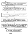
- Figure 4 illustrates a method according to the invention, the method comprising steps for sending a first reply and a second reply from the server to the client.
- the client 41 sends to the server a request according to operation code 3 containing a certain reference marking-
- the request is received 42 at the server, where the operation contained by the request is executed, as a response to which a reply message is formed.
- a reply containing operation code 3 and the data specified by the reference marking is sent from the server to the client.
- the client receives 43 the reply and it is checked to see whether the information of the reply are changed in relation to the data received earlier, In case the data have changed, the client sends 44 to the server a second request containing a certain second operation code (in this disclosure operation code 101) having the same reference marking.
- the server receives 45 the second request, executes the operation of the second request and sends a second reply to the client, containing a second operation code and the data specified by the reference marking.
- the client receives the second reply.
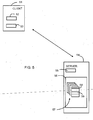
- FIG. 5 illustrates an arrangement according to the invention.
- the arrangement comprises a client apparatus 51 comprising communication means 52 for forming requests and receiving replies according to the Modbus protocol.
- the communication means are arranged to form a request according to operation code 3 having a certain reference marking for commencing receiving alarm data from the server apparatus.
- the client apparatus 51 also comprises checking means 53 for checking whether the received data of operation code 3 and the reference marking have changed in relation to the data received earlier.
- the communication means are also arranged for sending from the client 51 to the server 54 a second request according to a second operation code having the same reference marking in case the data are considered changed on the basis of the check performed by the checking means.
- the arrangement can also comprise server means 54 comprising first means 55 for receiving requests and for sending replies according to the Modbus protocol and other means 56 for executing the operations of the requests.
- the other means comprise primary tables 57 comprising Modbus registers.
- a certain register 58 of a certain primary table is arranged to represent a 16 bit line indicating alarm events, to which register the operation code 3 and a certain reference marking point to.
- the second register part 59 of the primary table is arranged to represent a data of 16*48 bits of which each 16 bits represents the time stamp of a certain alarm event.
- a certain second operation code and the same reference marking point to the second register part is provided.
- the realization according to the invention is simple and easy to carry out.
- the size of the second message is easier to specify so as to be suitable.
- a 48 bit time stamp will be sufficient for thousands of years and it can be used to achieve an accuracy of millisecond level,
- a time stamp of another size could naturally also be used, such as a 56 bit time stamp, whereby a considerably higher accuracy could be achieved.
- the operation of the invention can also be changed so that the time stamps are always requested when there is an alarm event in the server, i.e. always when the value of any bit of the first reply is one.
Landscapes
- Engineering & Computer Science (AREA)
- Human Computer Interaction (AREA)
- Physics & Mathematics (AREA)
- General Physics & Mathematics (AREA)
- Automation & Control Theory (AREA)
- Computer Networks & Wireless Communication (AREA)
- Signal Processing (AREA)
- Computer And Data Communications (AREA)
- Maintenance And Management Of Digital Transmission (AREA)
Description
- The present invention relates to transmitting alarm data in a client/server environment, in which Modbus communication is used for transmitting alarm data from the server to the client. The word client refers to an apparatus connected to the data communication network, requesting data from another apparatus connected to the data communication network. The word server refers to an apparatus connected to the data communication network, sending data to another apparatus connected to the data communication network. Server and client functions can be combined in the same apparatus.
- Modbus, as described in "modbus application protocol specification V1.1b", is a data communication protocol commonly used in industry. It is based on requests and replies. The client sends a request to the server and the server sends a reply to the request. An HMI apparatus is a typical client and a PLC controller is a typical server. The protocol is an application level data communication protocol, i.e. it is on
level 7 in the OSI model. Use of Modbus has branched out from traditional industrial applications to other areas, such as to vessels for monitoring the operations of diesel engines. - In Modbus, the data are transmitted in PDU units 1 (Protocol Data Unit) comprising an
operation code field 2 and adata field 3. The operation code field specifies the desired operation and the data field contains additional information used by the server for executing the operation specified by the operation code field. When the server has executed the desired operation, the data field of the PDU reply sent by the server contains the information requested by the client. Because in practice Modbus communication are arranged to be transmitted in a certain network, such as TCP/IP network or Ethernet, a network type-specific ADU unit 4 (Application Data Unit) is needed for transmitting the data.Figure 1 illustrates how thePDU unit 1 is located inside theADU unit 4. Anadditional address field 5 containing the server address is arranged in the beginning of the ADU unit. Acheck field 6 for checking the error free transmission of the ADU unit. - The Modbus architecture has interfaces for applications on the client and server side. The vendors of applications/apparatuses make a product-specific mapping between the Modbus interface and the application. Thus the protocol provides a certain interface model for vendors to provide a compatible product therewith.
- The server interface comprises a Modbus data model. The data model consists of four primary tables, each containing 65536 data entries. The data field of the PDU contains a reference marking to data entries pre-mapped by the apparatus manufacturer.
- Application environments monitoring the status of a number of apparatuses usually utilize a centralized monitoring unit. In a vessel environment, for example, the apparatuses to be monitored are various components of the motor and the monitoring unit is an HMI unit on the bridge of the vessel. As the status of a motor part exceeds certain limits, the HMI apparatus must trigger an alarm to the personnel on the bridge. The data caused by the alarm, i.e. alarm data, must be sent to the monitoring unit by the motor. The alarm data contains data information the status of the component as well as a time stamp. Often a number of alarms and other events happen at the same time. If a time stamp is not available, the HMI apparatus marks the reception time of the alarm as the time stamp. Because the HMI apparatus polls (sends a request for events to the servers) at certain intervals, a large number of alarms and events can have happened between polls. Thus, arranging the events and alarms on the basis reception time stamp is impossible. Because of this it is very time-consuming to find out the original cause of the alarm, for example the stopping of the engine.
- The Modbus protocol does not specify how the alarm data signal is transmitted from the server to the client, e.g. from the motor to the HMI apparatus. There are manufacturer-specific methods for transmitting alarm data signal, the methods, however, requiring relatively complex realizations in both the client and server ends in order to be operative. One method is to transfer the sequencer time of the server. The sequencer time is time Ta, Tb, Tc... until a certain synchronized point in time. See
figure 2 . The server utilizes a certain reoccurring synchronized point of time T1, T2, T3... from which the sequencer commences calculating the time. The sequencer time Ta, Tb, Tc... is transferred as 16 bit data in thedata field 3 of the Modbus PDU unit. The client must reconstruct the received time into a usable synchronized time. Reconstruction is relatively difficult in this method. - The aim of the invention is to form a simple and easily realizable method of transferring the alarm data from the server to the client. The aim is achieved using means described in the main claim. In a solution according to the invention the alarm data is sent from the server to the client in two steps. In the first step the system sends the information about the occurrence of at least one alarm event. In the second step the alarm event specific time stamps are sent. Preferably the time stamp information is already in such a form that in can be used as such and it can be relatively easily coded into a more usable form. Only a normal decoding, executed in any case, of the signal structure is done.
- The method of transferring the alarm data from the server to the client via Modbus data communication comprises the following steps:
- sending from the client to the server a request according to
operation code 3 containing a certain reference marking, - receiving the request at the server and executing the operation of the request and sending to the client a reply containing
operation code 3 and the data specified in the reference marking, - receiving the reply at the client and checking whether the information of the reply are changed in relation to the data received earlier,
- In case the data have changed, sending from the client to the server a second request containing a certain second operation code having the same reference marking,
- receiving the second request at the server and executing the operation of the second request and sending to the client a second reply containing a second operation code and the data specified in the reference marking, and
- receiving the second reply at the client.
- The client apparatus of the arrangement according to the invention is arranged to use Modbus data communication for requesting the data from the server apparatus. The client apparatus comprises communication means for forming requests and for receiving replies according to the Modbus protocol. The communication means are arranged to form a request according to
operation code 3 having a certain reference marking for commencing receiving alarm data from the server apparatus. The client apparatus also comprises checking means for checking whether the received data ofoperation code 3 and the reference marking have changed in relation to the data received earlier. - The communication means are also arranged for sending from the client to the server a second request according to a second operation code having the same reference marking in case the data are found to have changed on the basis of the check performed by the checking means.
- The server apparatus according to the invention is arranged to use Modbus data communication for sending data to the client apparatus, the server apparatus comprising first means for receiving requests and sending replies according to the Modbus protocol and second means for performing the operations of the requests. The second means comprise primary tables comprising Modbus registers. A certain register of a certain primary table is arranged to represent a 16 bit line indicating alarm events, to which register the
operation code 3 and a certain reference marking point to. The second register part of the primary table is arranged to represent 16*48 bit data, from which each 48 bits represent a time stamp of a certain alarm event. The certain second operation code and the same reference marking point to the second register part. - In the following the invention is described in more detail by reference to the appended figures, in which
-
Figure 1 illustrates an example of the structure of the Modbus message, -
Figure 2 illustrates an example of a prior art method of forming a time stamp, -
Figure 3 illustrates an example of the contents of messages according to the invention, -
Figure 4 is a flow diagram of the method according to the invention, and -
Figure 5 illustrates an example of the arrangements according to the invention. -
Figure 3 illustrates a 16-bit data register 31 in which each bit can describe a certain alarm event. Usually, the numbering of bits starts from zero, so the ordinal number of the last bit is 15.Bit 0 can, for example, describe the temperature of the main bearing SF,bit 2 can describe alarm-triggering exceeding of the temperature of the main bearing ALM andbit 5 can describe exceeding the critical temperature of the main bearing SHD, causing shut down of the engine. All bits are not necessarily specified to describe the statuses of the motor. When the temperature of the main bearing increases too much, the value of the corresponding bit changes from zero to one. - The data register is in the memory of the server. The client apparatus receives the data of the data register by sending to the Modbus a request according to
operation code 3 containing a reference number, i.e. a reference marking pointing to the register. -
Operation code 3 is used for reading the registers. The request comprises indication of the operation code, the reference number of the first register to be read and the amount of registers to be read. The request contains 5 bytes, whereby the contents of the PDU can be, for example, as follows: - Byte 0: Operation code = 03 (hexadecimal system is usually used)
- Bytes 1-2: reference number (such as 7078)
- Bytes 3-4: the number of registers to be read (e.g. 1).
- The server receives the request and executes the operation defined by the operation code, i.e. reads the register to which the received reference number points to. The server forms a reply sent to the client. The operation code of the PDU reply indicates the operation code of the request, i.e. number three. The data field contains two bytes/register, which in this example is 2 bytes containing the 16 bits of
figure 3 . In case an error has occurred in a data point or the operation, an error message is sent as a reply. In the error message reply the operation code field contains an error operation code and a field exception code describing the error. - The client checks on the basis of the received register data whether the data have changed in relation to a previously received register data. This enables checking for new alarms. In case there are no new alarms, the client apparatus does not take any further actions, but performs a
new operation code 3 request after a certain interval. In case there are new alarms, the client apparatus sends another request containing a certain second operation code and the same reference number as theoperation code 3 request. In this illustration the second operation code is 101, but it can also be another operation code specified to execute the same operation. Operation code 101 and the same reference number are used for transmitting the time stamps from the server to the client. The second request is, e.g.: - Byte 0: operation code = 65 (hex)
- Byte 1-2: reference number (such as 7078)
- Byte 3: bit number (e.g. 255, i.e. all time stamps of the reply)
- Byte 4: error log = 1 (always 1)
- Byte 5: not used, always zero.
- The server processes this request in the same way as the
operation code 3 request. The reply is also formed similarly. As each operation code defines its own operation, the operation code 101 defines that the reply to be formed contains 6 bytes for indicating the time stamp of each alarm event. A single time stamp is thereby 48 bits. The reply can, for example, be: - Byte 0: operation code = 65 (hexadecimal number corresponding to number 101)
- Byte 1: the number of the following bytes of the reply
- Bytes 2-7: time stamp for
bit 0 of the first reply - Bytes 8-13:1 time stamp for
bit 1 of the first reply - Bytes 14-19: 2 time stamp for
bit 2 of the first reply - Bytes 20-25: time stamp for
bit 3 of the first reply - Bytes 26-31: time stamp for
bit 4 of the first reply - Bytes 32-37: time stamp for
bit 5 of the first reply - Bytes 38-43: time stamp for
bit 6 of the first reply - Bytes 44-49: time stamp for
bit 7 of the first reply - Bytes 50-55: time stamp for
bit 8 of the first reply - Bytes 56-61: time stamp for
bit 9 of the first reply - Bytes 62-67: time stamp for
bit 10 of the first reply - Bytes 68-73: time stamp for
bit 11 of the first reply - Bytes 74-79: time stamp for
bit 12 of the first reply - Bytes 80-85: time stamp for
bit 13 of the first reply - Bytes 86-91: time stamp for
bit 14 of the first reply - Bytes 92-97: time stamp for
bit 15 of the first reply - Bytes 98-99: not used, always zero.
- Each time stamp is usually marked so that the most significant byte MSB is the first one and the least significant byte LSB is the last one, for example byte 80 = MSB, byte 85 = LSB. In case an error has occurred in a data point or the operation, an error message is sent as a reply.
- Byte 0: error code = E5 (hex)
- Byte 1: exception code = 01 or 02.
-
Figure 3 shows the time stamps forbits reply 32. The time stamps of these bits can in hexadecimal numbers be, for example - 010F51CD8F73: time stamp for bit 0 -> 05/12/2006 8:49:23,315 (SF, TE701)
- 010F51CEA47A: time stamp for
bit 2 → 05/12/2006 8:50:34,234 (ALM, TE701) - 010F51CEA779: time stamp for
bit 5 → 05/12/2006 8:50:35,001 (SHD, TE701) - There is no time stamp for other bits, so their values are marked as zero in the reply. The request does not, however, have to ask for all time stamps, but only some time stamps, such as
- Byte 0: FC = 65 (hex)
- Byte 1-2: reference number (such as 7078)
- Byte 3: bit number (e.g. 2, i.e. request for the time stamp the third bit)
- Byte 4: error log = 1 (always 1)
- Byte 5: not used, always zero.
- Byte 0: FC = 65 (hex)
- Byte 1: number of bytes in the reply, 08
- Bytes 2-7: 48 bit time stamp for
bit 2 010F51CEA47A → 05/12/2006 8:50:34,234 (ALM, TE701) - Byte 8-9: not used, always zero.
-
Figure 4 illustrates a method according to the invention, the method comprising steps for sending a first reply and a second reply from the server to the client. first, theclient 41 sends to the server a request according tooperation code 3 containing a certain reference marking- The request is received 42 at the server, where the operation contained by the request is executed, as a response to which a reply message is formed. A reply containingoperation code 3 and the data specified by the reference marking is sent from the server to the client. The client receives 43 the reply and it is checked to see whether the information of the reply are changed in relation to the data received earlier, In case the data have changed, the client sends 44 to the server a second request containing a certain second operation code (in this disclosure operation code 101) having the same reference marking. The server receives 45 the second request, executes the operation of the second request and sends a second reply to the client, containing a second operation code and the data specified by the reference marking. The client receives the second reply. -
Figure 5 illustrates an arrangement according to the invention. The arrangement comprises aclient apparatus 51 comprising communication means 52 for forming requests and receiving replies according to the Modbus protocol. The communication means are arranged to form a request according tooperation code 3 having a certain reference marking for commencing receiving alarm data from the server apparatus. Theclient apparatus 51 also comprises checking means 53 for checking whether the received data ofoperation code 3 and the reference marking have changed in relation to the data received earlier. The communication means are also arranged for sending from theclient 51 to the server 54 a second request according to a second operation code having the same reference marking in case the data are considered changed on the basis of the check performed by the checking means. - The arrangement can also comprise server means 54 comprising first means 55 for receiving requests and for sending replies according to the Modbus protocol and
other means 56 for executing the operations of the requests. The other means comprise primary tables 57 comprising Modbus registers. Acertain register 58 of a certain primary table is arranged to represent a 16 bit line indicating alarm events, to which register theoperation code 3 and a certain reference marking point to. Thesecond register part 59 of the primary table is arranged to represent a data of 16*48 bits of which each 16 bits represents the time stamp of a certain alarm event. A certain second operation code and the same reference marking point to the second register part. - The realization according to the invention is simple and easy to carry out. As the time stamp is transmitted by another message, the size of the second message is easier to specify so as to be suitable. A 48 bit time stamp will be sufficient for thousands of years and it can be used to achieve an accuracy of millisecond level, A time stamp of another size could naturally also be used, such as a 56 bit time stamp, whereby a considerably higher accuracy could be achieved. The operation of the invention can also be changed so that the time stamps are always requested when there is an alarm event in the server, i.e. always when the value of any bit of the first reply is one.
- In the light of the above description and its examples it is obvious that the embodiment according to the invention can be realized in a number of ways. It is obvious that the invention is not limited to the examples mentioned here, but that the invention can be realized by a number of different embodiments.
- Thus, any inventive embodiment can be carried out within the scope of the invention.
Claims (5)
- A method of transmitting alarm data from the server to the client via Modbus data communication, the method comprising the following steps:- sending from the client to the server a request according to operation code 3 containing a certain reference marking (41),- receiving the request at the server and executing the operation of the request and sending to the client a reply containing operation code 3 and the data specified in the reference marking (42), said method characterized in that:- receiving the reply at the client and checking whether the information of the reply are changed in relation to the data received earlier (43),- in case the data have changed, sending from the client to the server a second request containing a certain second operation code having the same reference marking (44),- receiving the second request at the server and executing the operation of the second request and sending to the client a second reply containing the data specified in a second operation code and the reference marking (45), and- receiving the second reply at the client (46).
- A method according to claim 1, characterized in that the first data received by the client comprises 16 bits (31) of which each bit indicates a certain alarm event and the second message received by the client comprises 16*48 bits (32) of which each 48 bits indicates a time stamp for the corresponding alarm event of the first message.
- A method according to claim 2, characterized in that the second operation code is 101.
- An arrangement comprising a client apparatus (51) arranged to use Modbus data communication for requesting data from a server apparatus, the client apparatus comprising communications means (52) for forming requests and receiving replies according to the Modbus protocol, wherein the communication means (52) are provided to form a request according to operation code 3 having a certain reference marking for commencing reception of alarm data from the server apparatus, the client apparatus (51) characterized by additionally comprising checking means (53) for checking whether the received data according to operation code 3 and the reference marking have changed in relation to the previously received corresponding data,
the communication means (52) being also arranged for sending a second request according to a second operation code having the same reference marking from the client to the server in case the data are found to have changed on the basis of the check performed by the checking means (53). - An arrangement according to claim 4, comprising a server apparatus (54) arranged to use Modbus data communication for sending data to a client apparatus (51), the apparatus comprising first means (55) for receiving requests and sending replies according to Modbus protocol and a second means (56) for executing the operations of the requests, the second means comprising primary tables (57) comprising Modbus registers, characterized in that a certain register (58) of a certain primary table is arranged to represent a 16 bit line indicating alarm events and into which register the operation code 3 and the certain reference marking point to, the second register part (59) of the same primary table being arranged to represent a 16*48 bit data, of which each 48 bits corresponds to a time stamp of a certain alarm event while the second operation code and the same reference marking point to the second register part (59).
Applications Claiming Priority (2)
| Application Number | Priority Date | Filing Date | Title |
|---|---|---|---|
| FI20075128A FI121494B (en) | 2007-02-21 | 2007-02-21 | Method and apparatus for transmitting alarm data from a server to a subscriber via a Modbus communication connection |
| PCT/FI2008/050045 WO2008102053A1 (en) | 2007-02-21 | 2008-02-06 | Method and apparatus for transmitting alarm data from the server to the client via modbus communication |
Publications (2)
| Publication Number | Publication Date |
|---|---|
| EP2122425A1 EP2122425A1 (en) | 2009-11-25 |
| EP2122425B1 true EP2122425B1 (en) | 2014-10-15 |
Family
ID=37832276
Family Applications (1)
| Application Number | Title | Priority Date | Filing Date |
|---|---|---|---|
| EP08709313.4A Active EP2122425B1 (en) | 2007-02-21 | 2008-02-06 | Method and arrangement for transmitting alarm data from the server to the client via MODBUS communication |
Country Status (3)
| Country | Link |
|---|---|
| EP (1) | EP2122425B1 (en) |
| FI (1) | FI121494B (en) |
| WO (1) | WO2008102053A1 (en) |
Families Citing this family (1)
| Publication number | Priority date | Publication date | Assignee | Title |
|---|---|---|---|---|
| CN111640287A (en) * | 2020-05-27 | 2020-09-08 | 红云红河烟草(集团)有限责任公司 | Communication calling method of cigarette production line |
Family Cites Families (2)
| Publication number | Priority date | Publication date | Assignee | Title |
|---|---|---|---|---|
| US5862391A (en) * | 1996-04-03 | 1999-01-19 | General Electric Company | Power management control system |
| US6906630B2 (en) * | 2001-02-28 | 2005-06-14 | General Electric Company | Transformer management system and method |
-
2007
- 2007-02-21 FI FI20075128A patent/FI121494B/en not_active IP Right Cessation
-
2008
- 2008-02-06 WO PCT/FI2008/050045 patent/WO2008102053A1/en not_active Ceased
- 2008-02-06 EP EP08709313.4A patent/EP2122425B1/en active Active
Also Published As
| Publication number | Publication date |
|---|---|
| EP2122425A1 (en) | 2009-11-25 |
| FI20075128L (en) | 2008-08-22 |
| FI121494B (en) | 2010-11-30 |
| FI20075128A0 (en) | 2007-02-21 |
| WO2008102053A1 (en) | 2008-08-28 |
Similar Documents
| Publication | Publication Date | Title |
|---|---|---|
| CN101351752B (en) | Method for monitoring installations by means of a field bus used in process automation technology | |
| US6628992B2 (en) | Remote terminal unit | |
| US6961753B1 (en) | Enterprise server for communication for a supervisory control and data acquisition (SCADA) System | |
| US7693688B2 (en) | Field bus distribution unit | |
| JP4769808B2 (en) | Interface modules used in Fieldbus device networks and Internet-based and non-Internet-based process control networks | |
| CN101165623B (en) | Apparatus and method for incorporating wireless data into an established process control system | |
| US8019546B1 (en) | Tsunami monitoring system | |
| CA2019373C (en) | Interrupt structure for network interface circuit | |
| WO2004070480A2 (en) | Interface module for use with a modbus device network and a fieldbus device network | |
| RU2004129311A (en) | CREATION OF INTEGRATED WARNINGS IN A TECHNOLOGICAL INSTALLATION | |
| US8966117B1 (en) | System for discovering routers in a communication path of a supervisory control and data acquisition system | |
| CN111740879A (en) | Data acquisition and data forwarding gateway implementation method | |
| Bansal et al. | Communication protocols used for industrial automation | |
| CN217428147U (en) | Gateway with edge computing function and capable of accessing industrial Internet of things | |
| US9100318B1 (en) | Method for discovering routers in a communication path of a supervisory control and data acquisition system | |
| EP2122425B1 (en) | Method and arrangement for transmitting alarm data from the server to the client via MODBUS communication | |
| CN117527928B (en) | A data processing method and system based on SCADA | |
| US11609891B2 (en) | Method for establishing network communication by means of OPC UA | |
| Zhang et al. | Design of temperature remote monitoring system based on stm32 | |
| US11514018B2 (en) | Method and data conversion unit for monitoring an automation system | |
| CN102291292A (en) | Method for EPA to FFH1 protocol conversion and scheduling | |
| JPH1188967A (en) | Measurement station data collection device | |
| CN114500148B (en) | Conversion device, access method, electronic equipment and storage medium of PA equipment | |
| US12231506B2 (en) | Method for diagnosing the operation of an edge device | |
| US20250119319A1 (en) | Application aware modbus gateway |
Legal Events
| Date | Code | Title | Description |
|---|---|---|---|
| PUAI | Public reference made under article 153(3) epc to a published international application that has entered the european phase |
Free format text: ORIGINAL CODE: 0009012 |
|
| 17P | Request for examination filed |
Effective date: 20090722 |
|
| AK | Designated contracting states |
Kind code of ref document: A1 Designated state(s): AT BE BG CH CY CZ DE DK EE ES FI FR GB GR HR HU IE IS IT LI LT LU LV MC MT NL NO PL PT RO SE SI SK TR |
|
| DAX | Request for extension of the european patent (deleted) | ||
| GRAP | Despatch of communication of intention to grant a patent |
Free format text: ORIGINAL CODE: EPIDOSNIGR1 |
|
| INTG | Intention to grant announced |
Effective date: 20140508 |
|
| GRAS | Grant fee paid |
Free format text: ORIGINAL CODE: EPIDOSNIGR3 |
|
| GRAA | (expected) grant |
Free format text: ORIGINAL CODE: 0009210 |
|
| AK | Designated contracting states |
Kind code of ref document: B1 Designated state(s): AT BE BG CH CY CZ DE DK EE ES FI FR GB GR HR HU IE IS IT LI LT LU LV MC MT NL NO PL PT RO SE SI SK TR |
|
| REG | Reference to a national code |
Ref country code: GB Ref legal event code: FG4D Ref country code: CH Ref legal event code: EP |
|
| REG | Reference to a national code |
Ref country code: IE Ref legal event code: FG4D |
|
| REG | Reference to a national code |
Ref country code: AT Ref legal event code: REF Ref document number: 691939 Country of ref document: AT Kind code of ref document: T Effective date: 20141115 |
|
| REG | Reference to a national code |
Ref country code: DE Ref legal event code: R096 Ref document number: 602008034887 Country of ref document: DE Effective date: 20141127 |
|
| REG | Reference to a national code |
Ref country code: NL Ref legal event code: T3 |
|
| REG | Reference to a national code |
Ref country code: AT Ref legal event code: MK05 Ref document number: 691939 Country of ref document: AT Kind code of ref document: T Effective date: 20141015 |
|
| REG | Reference to a national code |
Ref country code: LT Ref legal event code: MG4D |
|
| PG25 | Lapsed in a contracting state [announced via postgrant information from national office to epo] |
Ref country code: LT Free format text: LAPSE BECAUSE OF FAILURE TO SUBMIT A TRANSLATION OF THE DESCRIPTION OR TO PAY THE FEE WITHIN THE PRESCRIBED TIME-LIMIT Effective date: 20141015 Ref country code: FI Free format text: LAPSE BECAUSE OF FAILURE TO SUBMIT A TRANSLATION OF THE DESCRIPTION OR TO PAY THE FEE WITHIN THE PRESCRIBED TIME-LIMIT Effective date: 20141015 Ref country code: ES Free format text: LAPSE BECAUSE OF FAILURE TO SUBMIT A TRANSLATION OF THE DESCRIPTION OR TO PAY THE FEE WITHIN THE PRESCRIBED TIME-LIMIT Effective date: 20141015 Ref country code: PT Free format text: LAPSE BECAUSE OF FAILURE TO SUBMIT A TRANSLATION OF THE DESCRIPTION OR TO PAY THE FEE WITHIN THE PRESCRIBED TIME-LIMIT Effective date: 20150216 Ref country code: NO Free format text: LAPSE BECAUSE OF FAILURE TO SUBMIT A TRANSLATION OF THE DESCRIPTION OR TO PAY THE FEE WITHIN THE PRESCRIBED TIME-LIMIT Effective date: 20150115 Ref country code: IS Free format text: LAPSE BECAUSE OF FAILURE TO SUBMIT A TRANSLATION OF THE DESCRIPTION OR TO PAY THE FEE WITHIN THE PRESCRIBED TIME-LIMIT Effective date: 20150215 |
|
| PG25 | Lapsed in a contracting state [announced via postgrant information from national office to epo] |
Ref country code: GR Free format text: LAPSE BECAUSE OF FAILURE TO SUBMIT A TRANSLATION OF THE DESCRIPTION OR TO PAY THE FEE WITHIN THE PRESCRIBED TIME-LIMIT Effective date: 20150116 Ref country code: HR Free format text: LAPSE BECAUSE OF FAILURE TO SUBMIT A TRANSLATION OF THE DESCRIPTION OR TO PAY THE FEE WITHIN THE PRESCRIBED TIME-LIMIT Effective date: 20141015 Ref country code: PL Free format text: LAPSE BECAUSE OF FAILURE TO SUBMIT A TRANSLATION OF THE DESCRIPTION OR TO PAY THE FEE WITHIN THE PRESCRIBED TIME-LIMIT Effective date: 20141015 Ref country code: LV Free format text: LAPSE BECAUSE OF FAILURE TO SUBMIT A TRANSLATION OF THE DESCRIPTION OR TO PAY THE FEE WITHIN THE PRESCRIBED TIME-LIMIT Effective date: 20141015 Ref country code: CY Free format text: LAPSE BECAUSE OF FAILURE TO SUBMIT A TRANSLATION OF THE DESCRIPTION OR TO PAY THE FEE WITHIN THE PRESCRIBED TIME-LIMIT Effective date: 20141015 Ref country code: SE Free format text: LAPSE BECAUSE OF FAILURE TO SUBMIT A TRANSLATION OF THE DESCRIPTION OR TO PAY THE FEE WITHIN THE PRESCRIBED TIME-LIMIT Effective date: 20141015 Ref country code: AT Free format text: LAPSE BECAUSE OF FAILURE TO SUBMIT A TRANSLATION OF THE DESCRIPTION OR TO PAY THE FEE WITHIN THE PRESCRIBED TIME-LIMIT Effective date: 20141015 |
|
| REG | Reference to a national code |
Ref country code: DE Ref legal event code: R097 Ref document number: 602008034887 Country of ref document: DE |
|
| PG25 | Lapsed in a contracting state [announced via postgrant information from national office to epo] |
Ref country code: RO Free format text: LAPSE BECAUSE OF FAILURE TO SUBMIT A TRANSLATION OF THE DESCRIPTION OR TO PAY THE FEE WITHIN THE PRESCRIBED TIME-LIMIT Effective date: 20141015 Ref country code: SK Free format text: LAPSE BECAUSE OF FAILURE TO SUBMIT A TRANSLATION OF THE DESCRIPTION OR TO PAY THE FEE WITHIN THE PRESCRIBED TIME-LIMIT Effective date: 20141015 Ref country code: CZ Free format text: LAPSE BECAUSE OF FAILURE TO SUBMIT A TRANSLATION OF THE DESCRIPTION OR TO PAY THE FEE WITHIN THE PRESCRIBED TIME-LIMIT Effective date: 20141015 Ref country code: EE Free format text: LAPSE BECAUSE OF FAILURE TO SUBMIT A TRANSLATION OF THE DESCRIPTION OR TO PAY THE FEE WITHIN THE PRESCRIBED TIME-LIMIT Effective date: 20141015 Ref country code: DK Free format text: LAPSE BECAUSE OF FAILURE TO SUBMIT A TRANSLATION OF THE DESCRIPTION OR TO PAY THE FEE WITHIN THE PRESCRIBED TIME-LIMIT Effective date: 20141015 |
|
| PLBE | No opposition filed within time limit |
Free format text: ORIGINAL CODE: 0009261 |
|
| STAA | Information on the status of an ep patent application or granted ep patent |
Free format text: STATUS: NO OPPOSITION FILED WITHIN TIME LIMIT |
|
| 26N | No opposition filed |
Effective date: 20150716 |
|
| PG25 | Lapsed in a contracting state [announced via postgrant information from national office to epo] |
Ref country code: LU Free format text: LAPSE BECAUSE OF FAILURE TO SUBMIT A TRANSLATION OF THE DESCRIPTION OR TO PAY THE FEE WITHIN THE PRESCRIBED TIME-LIMIT Effective date: 20150206 |
|
| PG25 | Lapsed in a contracting state [announced via postgrant information from national office to epo] |
Ref country code: MC Free format text: LAPSE BECAUSE OF FAILURE TO SUBMIT A TRANSLATION OF THE DESCRIPTION OR TO PAY THE FEE WITHIN THE PRESCRIBED TIME-LIMIT Effective date: 20141015 |
|
| REG | Reference to a national code |
Ref country code: IE Ref legal event code: MM4A |
|
| REG | Reference to a national code |
Ref country code: FR Ref legal event code: ST Effective date: 20151030 |
|
| PG25 | Lapsed in a contracting state [announced via postgrant information from national office to epo] |
Ref country code: IE Free format text: LAPSE BECAUSE OF NON-PAYMENT OF DUE FEES Effective date: 20150206 |
|
| PG25 | Lapsed in a contracting state [announced via postgrant information from national office to epo] |
Ref country code: SI Free format text: LAPSE BECAUSE OF FAILURE TO SUBMIT A TRANSLATION OF THE DESCRIPTION OR TO PAY THE FEE WITHIN THE PRESCRIBED TIME-LIMIT Effective date: 20141015 Ref country code: FR Free format text: LAPSE BECAUSE OF NON-PAYMENT OF DUE FEES Effective date: 20150302 |
|
| PG25 | Lapsed in a contracting state [announced via postgrant information from national office to epo] |
Ref country code: MT Free format text: LAPSE BECAUSE OF FAILURE TO SUBMIT A TRANSLATION OF THE DESCRIPTION OR TO PAY THE FEE WITHIN THE PRESCRIBED TIME-LIMIT Effective date: 20141015 |
|
| PG25 | Lapsed in a contracting state [announced via postgrant information from national office to epo] |
Ref country code: HU Free format text: LAPSE BECAUSE OF FAILURE TO SUBMIT A TRANSLATION OF THE DESCRIPTION OR TO PAY THE FEE WITHIN THE PRESCRIBED TIME-LIMIT; INVALID AB INITIO Effective date: 20080206 Ref country code: BG Free format text: LAPSE BECAUSE OF FAILURE TO SUBMIT A TRANSLATION OF THE DESCRIPTION OR TO PAY THE FEE WITHIN THE PRESCRIBED TIME-LIMIT Effective date: 20141015 |
|
| PG25 | Lapsed in a contracting state [announced via postgrant information from national office to epo] |
Ref country code: TR Free format text: LAPSE BECAUSE OF FAILURE TO SUBMIT A TRANSLATION OF THE DESCRIPTION OR TO PAY THE FEE WITHIN THE PRESCRIBED TIME-LIMIT Effective date: 20141015 |
|
| PG25 | Lapsed in a contracting state [announced via postgrant information from national office to epo] |
Ref country code: BE Free format text: LAPSE BECAUSE OF FAILURE TO SUBMIT A TRANSLATION OF THE DESCRIPTION OR TO PAY THE FEE WITHIN THE PRESCRIBED TIME-LIMIT Effective date: 20141015 |
|
| REG | Reference to a national code |
Ref country code: CH Ref legal event code: U11 Free format text: ST27 STATUS EVENT CODE: U-0-0-U10-U11 (AS PROVIDED BY THE NATIONAL OFFICE) Effective date: 20260301 |
|
| PGFP | Annual fee paid to national office [announced via postgrant information from national office to epo] |
Ref country code: NL Payment date: 20260218 Year of fee payment: 19 |
|
| PGFP | Annual fee paid to national office [announced via postgrant information from national office to epo] |
Ref country code: GB Payment date: 20260219 Year of fee payment: 19 |
|
| PGFP | Annual fee paid to national office [announced via postgrant information from national office to epo] |
Ref country code: DE Payment date: 20260218 Year of fee payment: 19 |
|
| PGFP | Annual fee paid to national office [announced via postgrant information from national office to epo] |
Ref country code: IT Payment date: 20260224 Year of fee payment: 19 |
|
| PGFP | Annual fee paid to national office [announced via postgrant information from national office to epo] |
Ref country code: CH Payment date: 20260301 Year of fee payment: 19 |