EP2121144B1 - Aftertreatment injector anti-fouling device - Google Patents
Aftertreatment injector anti-fouling device Download PDFInfo
- Publication number
- EP2121144B1 EP2121144B1 EP08726682A EP08726682A EP2121144B1 EP 2121144 B1 EP2121144 B1 EP 2121144B1 EP 08726682 A EP08726682 A EP 08726682A EP 08726682 A EP08726682 A EP 08726682A EP 2121144 B1 EP2121144 B1 EP 2121144B1
- Authority
- EP
- European Patent Office
- Prior art keywords
- injector
- bore
- air
- nozzle
- outlet
- Prior art date
- Legal status (The legal status is an assumption and is not a legal conclusion. Google has not performed a legal analysis and makes no representation as to the accuracy of the status listed.)
- Active
Links
Images



Classifications
-
- F—MECHANICAL ENGINEERING; LIGHTING; HEATING; WEAPONS; BLASTING
- F01—MACHINES OR ENGINES IN GENERAL; ENGINE PLANTS IN GENERAL; STEAM ENGINES
- F01N—GAS-FLOW SILENCERS OR EXHAUST APPARATUS FOR MACHINES OR ENGINES IN GENERAL; GAS-FLOW SILENCERS OR EXHAUST APPARATUS FOR INTERNAL-COMBUSTION ENGINES
- F01N3/00—Exhaust or silencing apparatus having means for purifying, rendering innocuous, or otherwise treating exhaust
- F01N3/08—Exhaust or silencing apparatus having means for purifying, rendering innocuous, or otherwise treating exhaust for rendering innocuous
- F01N3/10—Exhaust or silencing apparatus having means for purifying, rendering innocuous, or otherwise treating exhaust for rendering innocuous by thermal or catalytic conversion of noxious components of exhaust
- F01N3/18—Exhaust or silencing apparatus having means for purifying, rendering innocuous, or otherwise treating exhaust for rendering innocuous by thermal or catalytic conversion of noxious components of exhaust characterised by methods of operation; Control
- F01N3/20—Exhaust or silencing apparatus having means for purifying, rendering innocuous, or otherwise treating exhaust for rendering innocuous by thermal or catalytic conversion of noxious components of exhaust characterised by methods of operation; Control specially adapted for catalytic conversion
- F01N3/206—Adding periodically or continuously substances to exhaust gases for promoting purification, e.g. catalytic material in liquid form, NOx reducing agents
- F01N3/2066—Selective catalytic reduction [SCR]
-
- F—MECHANICAL ENGINEERING; LIGHTING; HEATING; WEAPONS; BLASTING
- F01—MACHINES OR ENGINES IN GENERAL; ENGINE PLANTS IN GENERAL; STEAM ENGINES
- F01N—GAS-FLOW SILENCERS OR EXHAUST APPARATUS FOR MACHINES OR ENGINES IN GENERAL; GAS-FLOW SILENCERS OR EXHAUST APPARATUS FOR INTERNAL-COMBUSTION ENGINES
- F01N3/00—Exhaust or silencing apparatus having means for purifying, rendering innocuous, or otherwise treating exhaust
- F01N3/02—Exhaust or silencing apparatus having means for purifying, rendering innocuous, or otherwise treating exhaust for cooling, or for removing solid constituents of, exhaust
- F01N3/021—Exhaust or silencing apparatus having means for purifying, rendering innocuous, or otherwise treating exhaust for cooling, or for removing solid constituents of, exhaust by means of filters
- F01N3/023—Exhaust or silencing apparatus having means for purifying, rendering innocuous, or otherwise treating exhaust for cooling, or for removing solid constituents of, exhaust by means of filters using means for regenerating the filters, e.g. by burning trapped particles
- F01N3/025—Exhaust or silencing apparatus having means for purifying, rendering innocuous, or otherwise treating exhaust for cooling, or for removing solid constituents of, exhaust by means of filters using means for regenerating the filters, e.g. by burning trapped particles using fuel burner or by adding fuel to exhaust
- F01N3/0253—Exhaust or silencing apparatus having means for purifying, rendering innocuous, or otherwise treating exhaust for cooling, or for removing solid constituents of, exhaust by means of filters using means for regenerating the filters, e.g. by burning trapped particles using fuel burner or by adding fuel to exhaust adding fuel to exhaust gases
-
- F—MECHANICAL ENGINEERING; LIGHTING; HEATING; WEAPONS; BLASTING
- F01—MACHINES OR ENGINES IN GENERAL; ENGINE PLANTS IN GENERAL; STEAM ENGINES
- F01N—GAS-FLOW SILENCERS OR EXHAUST APPARATUS FOR MACHINES OR ENGINES IN GENERAL; GAS-FLOW SILENCERS OR EXHAUST APPARATUS FOR INTERNAL-COMBUSTION ENGINES
- F01N2610/00—Adding substances to exhaust gases
- F01N2610/03—Adding substances to exhaust gases the substance being hydrocarbons, e.g. engine fuel
-
- F—MECHANICAL ENGINEERING; LIGHTING; HEATING; WEAPONS; BLASTING
- F01—MACHINES OR ENGINES IN GENERAL; ENGINE PLANTS IN GENERAL; STEAM ENGINES
- F01N—GAS-FLOW SILENCERS OR EXHAUST APPARATUS FOR MACHINES OR ENGINES IN GENERAL; GAS-FLOW SILENCERS OR EXHAUST APPARATUS FOR INTERNAL-COMBUSTION ENGINES
- F01N2610/00—Adding substances to exhaust gases
- F01N2610/08—Adding substances to exhaust gases with prior mixing of the substances with a gas, e.g. air
-
- F—MECHANICAL ENGINEERING; LIGHTING; HEATING; WEAPONS; BLASTING
- F01—MACHINES OR ENGINES IN GENERAL; ENGINE PLANTS IN GENERAL; STEAM ENGINES
- F01N—GAS-FLOW SILENCERS OR EXHAUST APPARATUS FOR MACHINES OR ENGINES IN GENERAL; GAS-FLOW SILENCERS OR EXHAUST APPARATUS FOR INTERNAL-COMBUSTION ENGINES
- F01N2610/00—Adding substances to exhaust gases
- F01N2610/14—Arrangements for the supply of substances, e.g. conduits
- F01N2610/1453—Sprayers or atomisers; Arrangement thereof in the exhaust apparatus
-
- F—MECHANICAL ENGINEERING; LIGHTING; HEATING; WEAPONS; BLASTING
- F01—MACHINES OR ENGINES IN GENERAL; ENGINE PLANTS IN GENERAL; STEAM ENGINES
- F01N—GAS-FLOW SILENCERS OR EXHAUST APPARATUS FOR MACHINES OR ENGINES IN GENERAL; GAS-FLOW SILENCERS OR EXHAUST APPARATUS FOR INTERNAL-COMBUSTION ENGINES
- F01N3/00—Exhaust or silencing apparatus having means for purifying, rendering innocuous, or otherwise treating exhaust
- F01N3/08—Exhaust or silencing apparatus having means for purifying, rendering innocuous, or otherwise treating exhaust for rendering innocuous
- F01N3/10—Exhaust or silencing apparatus having means for purifying, rendering innocuous, or otherwise treating exhaust for rendering innocuous by thermal or catalytic conversion of noxious components of exhaust
- F01N3/24—Exhaust or silencing apparatus having means for purifying, rendering innocuous, or otherwise treating exhaust for rendering innocuous by thermal or catalytic conversion of noxious components of exhaust characterised by constructional aspects of converting apparatus
- F01N3/30—Arrangements for supply of additional air
-
- F—MECHANICAL ENGINEERING; LIGHTING; HEATING; WEAPONS; BLASTING
- F02—COMBUSTION ENGINES; HOT-GAS OR COMBUSTION-PRODUCT ENGINE PLANTS
- F02M—SUPPLYING COMBUSTION ENGINES IN GENERAL WITH COMBUSTIBLE MIXTURES OR CONSTITUENTS THEREOF
- F02M2200/00—Details of fuel-injection apparatus, not otherwise provided for
- F02M2200/06—Fuel-injection apparatus having means for preventing coking, e.g. of fuel injector discharge orifices or valve needles
-
- Y—GENERAL TAGGING OF NEW TECHNOLOGICAL DEVELOPMENTS; GENERAL TAGGING OF CROSS-SECTIONAL TECHNOLOGIES SPANNING OVER SEVERAL SECTIONS OF THE IPC; TECHNICAL SUBJECTS COVERED BY FORMER USPC CROSS-REFERENCE ART COLLECTIONS [XRACs] AND DIGESTS
- Y02—TECHNOLOGIES OR APPLICATIONS FOR MITIGATION OR ADAPTATION AGAINST CLIMATE CHANGE
- Y02T—CLIMATE CHANGE MITIGATION TECHNOLOGIES RELATED TO TRANSPORTATION
- Y02T10/00—Road transport of goods or passengers
- Y02T10/10—Internal combustion engine [ICE] based vehicles
- Y02T10/12—Improving ICE efficiencies
Definitions
- the invention relates to internal combustion engine exhaust systems and devices for injecting hydrocarbons and/or other substances into an exhaust gas flow of an internal combustion engine.
- a diesel particulate filtration device is an example of a device which may be used to comply with particulate emissions levels in a diesel engine.
- a diesel oxidation catalyst may be used to convert hydrocarbons and carbon monoxide to carbon dioxide and water vapor.
- a DOC can also be used in conjunction with a DPF device to raise the temperature of the DPF for regeneration, that is, removing collected carbon particulate matter.
- Lean NOx absorbers and Selective Catalytic Reduction (SCR) devices are examples of systems used for reducing NOx in the exhaust gases.
- Regeneration may be done by methods including injecting hydrocarbons into the exhaust flow.
- FIG. 1 shows schematically an internal combustion engine 5 with an exhaust system layout including a stack pipe or tailpipe 10, which disperses the exhaust gas to the environment, and exhaust aftertreatment devices, in this illustration, a diesel particulate filter 12, and a diesel oxidation catalyst 14.
- Figure 1 shows an injection device 16 mounted on the exhaust downstream of the exhaust side of the turbine 18 of a turbocompressor. Hydrocarbon injected by the injector 16 mixes with the exhaust gas and is oxidized when it comes into contact with the catalyst, releasing heat energy. The heated gases enter the diesel particulate filter and cause much of the accumulated particulate matter to oxidize.
- a problem with an injector mounted on an exhaust conduit is that particulate matter in the exhaust gases, which prior to the aftertreatment devices has not been filtered out, tends to collect on and foul the injector nozzle. This fouling or accumulated carbon deposits, can block the nozzle outlet or disrupt the flow pattern of the nozzle. A fouled nozzle requires cleaning, which results in vehicle downtime and maintenance costs.
- One anti-fouling device for an exhaust after treatment injector which addresses the problem of fouled nozzles id disclosed in US 5,522,218 .
- fouling can be prevented or diminished by creating a positive flow of air or another clean gas around the nozzle to inhibit the flow of exhaust gases from reaching the nozzle.
- a device in accordance with the invention includes a plate-shaped member having a bore to provide communication between the nozzle of the injector and an opening in the exhaust conduit.
- the plate-shaped member includes an inlet to receive air from an air source, and has defined therein a passageway to guide the received air to at least one outlet.
- the at least one outlet directs the air to the nozzle.
- the bore is defined by a throat section which opens to a frusto-conical shaped section and widens towards an exhaust conduit side of the member. The at least one outlet opens onto the throat section.
- the device directs air or another gas into a cavity in which a hydraulic flow nozzle is disposed to maintain a constant or nearly constant outward flow of gas so as to prevent the ingress of particles, materials or other contaminants that could be in the environment outside of the cavity (that is, the exhaust conduit 20).
- the anti-fouling device may be integrated into an injector outside the nozzle or integrated into the wall of an exhaust conduit 20.
- the at least one outlet may be formed as a hole.
- the at least one outlet may be formed as an air jet or nozzle shaped opening.
- the at least one outlet may be formed as a slot in the wall defining the bore. Other outlet shapes may be used.
- the bore may be shaped to define a cavity to receive the nozzle, the cavity defining the space around the nozzle and opening to an aperture to allow the injection of hydrocarbon or other substance from the injector into the exhaust pipe.
- the plate member includes a recess area surrounding the bore on a side that mates with the injector, which defines an annular gap around the injector nozzle.
- the passageway guides air to the recess area and annular gap, which causes the air to form a ring-shaped curtain around the nozzle.
- the passageway may be formed in part by a space between the injector body and a top surface of the plate.
- an anti-fouling device delivers air or another gas at a pressure higher than the pressure of exhaust gases in the exhaust conduit to hinder exhaust gas from contacting the injector nozzle.
- an anti-fouling device delivers air or another gas to a vicinity of an injector nozzle with sufficient velocity to prevent or hinder exhaust gas from contacting the nozzle.
- Figure 1 is a schematic drawing of an exhaust system of a heavy truck having aftertreatment devices and a hydrocarbon injector for regeneration of the devices;
- Figure 2 is a section view of an anti-fouling device in accordance with one embodiment of the invention mounted between an injection device and an exhaust pipe;
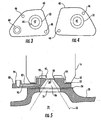
- Figure 3 is a top view of the anti-fouling device of Figure 2 ;
- Figure 4 is a bottom view of the anti-fouling device of Figure 2 ;
- Figure 5 is section view of an anti-fouling device in accordance with an alternative embodiment of the invention mounted between an injection device and exhaust pipe;
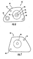
- Figure 6 is a top view of the anti-fouling device of Figure 5 ;
- Figure 7 is a bottom view of the anti-fouling device of Figure 5 ;
- Figure 8 is a section view of another alternative embodiment of the invention showing an anti-fouling device made in two parts;
- Figure 9 is a side section view of an insert part of the embodiment of Figure 8 ;
- Figure 10 is a top view of the insert part of Figure 9 .
- an anti-fouling device 40 in accordance with the invention is shown mounted on an exhaust conduit 20 between the exhaust conduit and a hydrocarbon injector 16.
- the device 40 in accordance with the invention is shown and described in the various embodiments as a plate shaped element, which here means a body capable of forming an interface between the injector and the exhaust conduit having features as described below.
- the anti-fouling device 40 of Figure 2 is shown in top view in Figure 3 and bottom view in Figure 4 .
- the injector 16 includes a nozzle 30 surrounded by a rim 32 that defines a space or cavity in which the injector nozzle is disposed.
- An insulating element 34 or a spacing element may be disposed radially inward of the rim 32 and is compressed between the injector 16 and a top surface 44 of the anti-fouling device 40.
- a first gasket 23 is positioned between the rim 32 and the top surface 44 of the device 40 to form a seal between the injector body 16 and the top surface.
- a second gasket 24 seals the anti-fouling device 40 to the exhaust pipe 20.
- injector 16 and anti-fouling device 40 may be mounted to the exhaust pipe 20 by any convenient means, and for example, by threaded fasteners (not shown) extending through mounting holes in the injector 16 and aligned mounting holes 46,48 in the anti-fouling device, and secured to threaded holes (not illustrated) formed in the wall of the exhaust pipe.
- the anti-fouling device 40 can include an upstanding collar to space the injector from the top surface of the anti-fouling device to create a cavity around the injector nozzle.
- the anti-fouling device 40 shown in Figures 2 , 3 and 4 is a plate-like element having a centrally located bore defined by an upward facing frustoconical surface or chamfer 50 and a downward facing frustoconical surface or chamfer 52 meeting at a throat area 42.
- the chamfer surfaces 50, 52 and throat 42 define an hourglass space, and together with the space bounded by the injector rim 32 and insulating element 34, define a cavity for the nozzle 30.
- the bore which includes the chamfers 50, 52 and the throat 42, is aligned with and opens to an aperture 26 in the exhaust pipe 20 to allow the injector 16 to inject hydrocarbon into an exhaust conduit interior 22.
- a spray pattern 36 as may be produced by the nozzle 30 is indicated by the broken lines 36.
- the anti-fouling device 40 includes an inlet 60 to receive air or another gas under pressure from a source (not illustrated).
- a passageway 62 formed in the plate member 40 connects the air inlet 60 to the upward facing chamfer 50 and includes an outlet 64 formed as an air jet, which is directed toward the injector nozzle 30.
- the outlet 64 directs a flow of air under pressure onto the injector nozzle 30, with sufficient volume of air to provide a flow of air in a vicinity of the injector nozzle 30 and outward from the nozzle cavity.
- the outward flow of air prevents the ingress of exhaust gases into the cavity, thus preventing fouling of the nozzle 30.
- the air or gas from the source is at a pressure higher than a pressure of exhaust gas in the exhaust conduit interior 22. Further, it is desired that the air or gas flow, at least in the vicinity of the injector nozzle 30 be at a velocity sufficiently high to prevent or hinder exhaust gas from contacting the injector nozzle 30.
- the outlet 64 may alternatively be formed as two or more outlets arranged on the upward facing chamfer 50 with appropriate modification of the passageway 62 to supply the outlets.
- a second outlet may be positioned opposite the outlet 64 shown in Figures 2 and 3 . If more than two outlets are used, they may be equally dispersed about the upward facing chamfer 50.
- the outlets air jets or nozzles
- the outlet may be directed to create a swirl pattern or vortex surrounding the injector nozzle 30.
- the outlet may be formed as one or more arc shaped or slotted outlets, or as a ring-shaped aperture in the upward facing chamfer 50.
- Figure 5 illustrates in section view an alternative embodiment of the and-fouling device 80.
- Figure 6 is a top view and
- Figure 7 is a bottom view of the anti-fouling device 80 of Figure 5 .
- the injector 16 and exhaust conduit 20 are identical to those illustrated in Figure 2 .
- the insulating element is omitted and the injector 16 is sealed to the top surface 82 of the anti-fouling device 80 by second gasket 23.
- the anti-fouling device 80 of Figure 5 includes a centrally located upstanding boss 84.
- a frustoconical bore 86 is formed in the boss 84 and body of the anti-fouling device 80, and diverges, that is, expands, downward from a top surface 90 of the boss.
- a shallow countersunk hole 88 forms a throat or entrance to the bore 86.
- the boss 84 has a height relative to the rim 32 that spaces the top surface 90 from the injector 16 to define a cavity or intermediate space between the injector 16 and the top surface 90 of the boss.
- the throat 88 defines a cavity or annular orifice 92 around the nozzle 30.
- An inlet 94 for receiving air from an air source is formed on the top surface 82 of the anti-fouling device.
- a passageway 96 leads from the air inlet 94 to the top surface 90 of the boss 84. Air flowing through the passageway 96 fills the cavity between the injector and the top surface 90 of the boss 84 and flows through the annular orifice 92 as a ring curtain of air surrounding the nozzle 30.
- the passageway 96 may be formed with additional openings on the top surface 90 of the boss 84 to improve the flow of air into the cavity. Air is provided in sufficient volume to create an outward flow of air into the exhaust diffuser 22 to prevent the ingress of exhaust gas into the bore area 86. In addition, the air is provided at a pressure higher than the pressure of the exhaust gas in the conduit interior 22. Further, the air velocity in the vicinity of the injector nozzle 30 is sufficiently high to prevent or hinder the exhaust gas from contacting the injector nozzle 30.
- the air source could be derived from the vehicle's pneumatic system, a turbocharger, supercharger system, or any convenient source of air.
- a dedicated air supply device could be provided, which could be powered by the vehicle electrical system.
- the air flow delivered to the nozzle may be a continuous flow or alternatively, a pulsed flow.
- Figure 8 shows an alternative embodiment of the plate member 100 of the invention formed as a base 101 and an insert part 120.
- the injector 16 and exhaust conduit 20 are the same, and the plate member 100 is disposed between the injector and the opening 26 on the exhaust conduit.
- an insert part is made separately to facilitate forming the bore and the internal passageway for received air.
- Figure 9 shows a front section view of an insert part 120 according to one embodiment.
- Figure 10 shows a top view of the insert part 120 of Figure 9 .
- Figure 8 for purposes of illustration, includes a representation of the insert part 120 of Figure 9 .
- the insert part may be secured in the base member in any appropriate manner.
- the plate member 100 is formed with a recess or seat 102 to accept an insert part 120.
- the plate member 100 includes an inlet 104 for receiving air from an air source and an internally formed passageway 106 to guide the received air to the seat 102.
- the plate member 100 includes a bore 108 formed as a frustoconical hole diverging toward the exhaust conduit 20 and aligned with the opening 26 in the exhaust conduit.
- the insert part 120 includes a bore formed in three parts, a recess 122 opening on a top surface 124 of the insert part, a throat 126 communicating with the recess 122 and disposed for alignment with the nozzle 30 of the injector 16, and a frustoconical hole 128 communicating with the throat and diverging toward the frustoconical bore 108 in the plate member 100.
- the frustoconical hole 126 in the insert part 120 and the frustoconical bore 104 in the plate member 100 form a continuous frustoconical outlet from the throat 126 to the opening 26 in the exhaust conduit 20.
- the insert member 120 also includes a flow passage 130 for air terminating in an outlet 132, in this case formed as an air jet, opening on the throat 126.
- An entrance 134 to the flow passage 130 aligns with and communicates with the passageway 106 formed in the plate member 100 to receive air guided therethrough.
- the air pressure and flow rate of air for the device will need to be determined by the operating characteristics of the engine and exhaust conduit on which the device of the invention is used. It is currently contemplated that the air supply will be unregulated. Alternatively, if necessary or desirable, the air supply may be regulated or actively controlled, as may best deliver air from the selected air source, which as mentioned, may be the vehicle pneumatic system, turbocharger system or supercharger system as sources or from a dedicated air supply device.
- the anti-fouling device is illustrated and described as a separate element disposed between the injector 16 and the exhaust conduit 20; however, those skilled in the art will recognize that the device may be integrated into the injector body outside of the nozzle or alternatively integrated into the wall of the exhaust conduit.
Landscapes
- Engineering & Computer Science (AREA)
- Chemical & Material Sciences (AREA)
- Combustion & Propulsion (AREA)
- Mechanical Engineering (AREA)
- General Engineering & Computer Science (AREA)
- Chemical Kinetics & Catalysis (AREA)
- Health & Medical Sciences (AREA)
- Toxicology (AREA)
- Exhaust Gas After Treatment (AREA)
Description
- The invention relates to internal combustion engine exhaust systems and devices for injecting hydrocarbons and/or other substances into an exhaust gas flow of an internal combustion engine.
- Stringent emissions regulations such as those imposed by U.S. and European regulatory officials have progressively reduced the amount of diesel particulate matter (DPM) and other gaseous constituents such as NOx allowed in the exhaust gases of diesel engines. The emissions levels proposed by the US07 and Euro 5 regulations are so low that they can be currently met only with the use of exhaust aftertreatment devices. A diesel particulate filtration device (DPF) is an example of a device which may be used to comply with particulate emissions levels in a diesel engine. A diesel oxidation catalyst (DOC) may be used to convert hydrocarbons and carbon monoxide to carbon dioxide and water vapor. A DOC can also be used in conjunction with a DPF device to raise the temperature of the DPF for regeneration, that is, removing collected carbon particulate matter. Lean NOx absorbers and Selective Catalytic Reduction (SCR) devices are examples of systems used for reducing NOx in the exhaust gases.
- It is necessary at times to inject substances into the engine exhaust to facilitate or initiate a function of an aftertreatment device. With diesel particulate filters, for example, it is sometimes necessary to raise the temperature of the exhaust gas to oxidize the collected particulate matter in the filter for removal, a process known as regeneration. Regeneration may be done by methods including injecting hydrocarbons into the exhaust flow.
- One method is to inject a hydrocarbon into the exhaust gas and use a catalytic device that elevates exhaust gas temperature by catalytically oxidizing the injected hydrocarbon.
Figure 1 shows schematically an internal combustion engine 5 with an exhaust system layout including a stack pipe ortailpipe 10, which disperses the exhaust gas to the environment, and exhaust aftertreatment devices, in this illustration, adiesel particulate filter 12, and adiesel oxidation catalyst 14.Figure 1 shows aninjection device 16 mounted on the exhaust downstream of the exhaust side of theturbine 18 of a turbocompressor. Hydrocarbon injected by theinjector 16 mixes with the exhaust gas and is oxidized when it comes into contact with the catalyst, releasing heat energy. The heated gases enter the diesel particulate filter and cause much of the accumulated particulate matter to oxidize. - A problem with an injector mounted on an exhaust conduit is that particulate matter in the exhaust gases, which prior to the aftertreatment devices has not been filtered out, tends to collect on and foul the injector nozzle. This fouling or accumulated carbon deposits, can block the nozzle outlet or disrupt the flow pattern of the nozzle. A fouled nozzle requires cleaning, which results in vehicle downtime and maintenance costs. One anti-fouling device for an exhaust after treatment injector which addresses the problem of fouled nozzles id disclosed in
US 5,522,218 . - According to the invention, fouling can be prevented or diminished by creating a positive flow of air or another clean gas around the nozzle to inhibit the flow of exhaust gases from reaching the nozzle.
- The invention proposes a device that can be mounted between the injector and the exhaust conduit that guides a flow of air or another clean gas to the nozzle. In its simplest form, a device in accordance with the invention includes a plate-shaped member having a bore to provide communication between the nozzle of the injector and an opening in the exhaust conduit. The plate-shaped member includes an inlet to receive air from an air source, and has defined therein a passageway to guide the received air to at least one outlet. The at least one outlet directs the air to the nozzle. The bore is defined by a throat section which opens to a frusto-conical shaped section and widens towards an exhaust conduit side of the member. The at least one outlet opens onto the throat section. The device directs air or another gas into a cavity in which a hydraulic flow nozzle is disposed to maintain a constant or nearly constant outward flow of gas so as to prevent the ingress of particles, materials or other contaminants that could be in the environment outside of the cavity (that is, the exhaust conduit 20).
- Alternatively, rather than being formed as a separate member, the anti-fouling device may be integrated into an injector outside the nozzle or integrated into the wall of an
exhaust conduit 20. - The at least one outlet may be formed as a hole. Alternatively, the at least one outlet may be formed as an air jet or nozzle shaped opening. According to another alternative, the at least one outlet may be formed as a slot in the wall defining the bore. Other outlet shapes may be used.
- According to one embodiment, the bore may be shaped to define a cavity to receive the nozzle, the cavity defining the space around the nozzle and opening to an aperture to allow the injection of hydrocarbon or other substance from the injector into the exhaust pipe.
- According to another embodiment, the plate member includes a recess area surrounding the bore on a side that mates with the injector, which defines an annular gap around the injector nozzle. The passageway guides air to the recess area and annular gap, which causes the air to form a ring-shaped curtain around the nozzle. The passageway may be formed in part by a space between the injector body and a top surface of the plate.
- According to the invention, an anti-fouling device delivers air or another gas at a pressure higher than the pressure of exhaust gases in the exhaust conduit to hinder exhaust gas from contacting the injector nozzle.
- According to the invention, an anti-fouling device delivers air or another gas to a vicinity of an injector nozzle with sufficient velocity to prevent or hinder exhaust gas from contacting the nozzle.
- The invention will be better understood by reference to the detailed description in conjunction with the appended drawings, in which:
-
Figure 1 is a schematic drawing of an exhaust system of a heavy truck having aftertreatment devices and a hydrocarbon injector for regeneration of the devices; -
Figure 2 is a section view of an anti-fouling device in accordance with one embodiment of the invention mounted between an injection device and an exhaust pipe; -
Figure 3 is a top view of the anti-fouling device ofFigure 2 ; -
Figure 4 is a bottom view of the anti-fouling device ofFigure 2 ; -
Figure 5 is section view of an anti-fouling device in accordance with an alternative embodiment of the invention mounted between an injection device and exhaust pipe; -
Figure 6 is a top view of the anti-fouling device ofFigure 5 ; -
Figure 7 is a bottom view of the anti-fouling device ofFigure 5 ; -
Figure 8 is a section view of another alternative embodiment of the invention showing an anti-fouling device made in two parts; -
Figure 9 is a side section view of an insert part of the embodiment ofFigure 8 ; and, -
Figure 10 is a top view of the insert part ofFigure 9 . - Referring to
Figure 2 , a first embodiment of ananti-fouling device 40 in accordance with the invention is shown mounted on anexhaust conduit 20 between the exhaust conduit and ahydrocarbon injector 16. Thedevice 40 in accordance with the invention is shown and described in the various embodiments as a plate shaped element, which here means a body capable of forming an interface between the injector and the exhaust conduit having features as described below. Theanti-fouling device 40 ofFigure 2 is shown in top view inFigure 3 and bottom view inFigure 4 . - The
injector 16 includes anozzle 30 surrounded by arim 32 that defines a space or cavity in which the injector nozzle is disposed. Aninsulating element 34 or a spacing element may be disposed radially inward of therim 32 and is compressed between theinjector 16 and atop surface 44 of theanti-fouling device 40. Afirst gasket 23 is positioned between therim 32 and thetop surface 44 of thedevice 40 to form a seal between theinjector body 16 and the top surface. Asecond gasket 24 seals theanti-fouling device 40 to theexhaust pipe 20. The assembly ofinjector 16 andanti-fouling device 40 may be mounted to theexhaust pipe 20 by any convenient means, and for example, by threaded fasteners (not shown) extending through mounting holes in theinjector 16 and alignedmounting holes - In the case of an injector not having a
rim 32 as shown inFigure 2 , theanti-fouling device 40 can include an upstanding collar to space the injector from the top surface of the anti-fouling device to create a cavity around the injector nozzle. - The
anti-fouling device 40 shown inFigures 2 ,3 and 4 is a plate-like element having a centrally located bore defined by an upward facing frustoconical surface orchamfer 50 and a downward facing frustoconical surface or chamfer 52 meeting at athroat area 42. Thechamfer surfaces throat 42 define an hourglass space, and together with the space bounded by theinjector rim 32 and insulatingelement 34, define a cavity for thenozzle 30. The bore, which includes thechamfers throat 42, is aligned with and opens to anaperture 26 in theexhaust pipe 20 to allow theinjector 16 to inject hydrocarbon into anexhaust conduit interior 22. Aspray pattern 36 as may be produced by thenozzle 30 is indicated by thebroken lines 36. - The
anti-fouling device 40 includes aninlet 60 to receive air or another gas under pressure from a source (not illustrated). Apassageway 62 formed in theplate member 40 connects theair inlet 60 to the upward facingchamfer 50 and includes anoutlet 64 formed as an air jet, which is directed toward theinjector nozzle 30. Theoutlet 64 directs a flow of air under pressure onto theinjector nozzle 30, with sufficient volume of air to provide a flow of air in a vicinity of theinjector nozzle 30 and outward from the nozzle cavity. The outward flow of air prevents the ingress of exhaust gases into the cavity, thus preventing fouling of thenozzle 30. Preferably, the air or gas from the source is at a pressure higher than a pressure of exhaust gas in theexhaust conduit interior 22. Further, it is desired that the air or gas flow, at least in the vicinity of theinjector nozzle 30 be at a velocity sufficiently high to prevent or hinder exhaust gas from contacting theinjector nozzle 30. - The
outlet 64 may alternatively be formed as two or more outlets arranged on the upward facingchamfer 50 with appropriate modification of thepassageway 62 to supply the outlets. For example, a second outlet may be positioned opposite theoutlet 64 shown inFigures 2 and3 . If more than two outlets are used, they may be equally dispersed about the upward facingchamfer 50. According to yet another alternative, the outlets (air jets or nozzles) may be directed to create a swirl pattern or vortex surrounding theinjector nozzle 30. Alternatively, the outlet may be formed as one or more arc shaped or slotted outlets, or as a ring-shaped aperture in the upward facingchamfer 50. These alternative arrangements may be formed by making thedevice 40 in two plates that are bonded after the passageways and apertures are formed. -
Figure 5 illustrates in section view an alternative embodiment of the and-foulingdevice 80.Figure 6 is a top view andFigure 7 is a bottom view of theanti-fouling device 80 ofFigure 5 . Theinjector 16 andexhaust conduit 20 are identical to those illustrated inFigure 2 . In the embodiment ofFigure 5 , the insulating element is omitted and theinjector 16 is sealed to thetop surface 82 of theanti-fouling device 80 bysecond gasket 23. - The
anti-fouling device 80 ofFigure 5 includes a centrally locatedupstanding boss 84. A frustoconical bore 86 is formed in theboss 84 and body of theanti-fouling device 80, and diverges, that is, expands, downward from atop surface 90 of the boss. A shallow countersunkhole 88 forms a throat or entrance to thebore 86. Theboss 84 has a height relative to therim 32 that spaces thetop surface 90 from theinjector 16 to define a cavity or intermediate space between theinjector 16 and thetop surface 90 of the boss. Thethroat 88 defines a cavity orannular orifice 92 around thenozzle 30. - An
inlet 94 for receiving air from an air source is formed on thetop surface 82 of the anti-fouling device. Apassageway 96 leads from theair inlet 94 to thetop surface 90 of theboss 84. Air flowing through thepassageway 96 fills the cavity between the injector and thetop surface 90 of theboss 84 and flows through theannular orifice 92 as a ring curtain of air surrounding thenozzle 30. Thepassageway 96 may be formed with additional openings on thetop surface 90 of theboss 84 to improve the flow of air into the cavity. Air is provided in sufficient volume to create an outward flow of air into theexhaust diffuser 22 to prevent the ingress of exhaust gas into thebore area 86. In addition, the air is provided at a pressure higher than the pressure of the exhaust gas in theconduit interior 22. Further, the air velocity in the vicinity of theinjector nozzle 30 is sufficiently high to prevent or hinder the exhaust gas from contacting theinjector nozzle 30. - As contemplated by the invention, the air source could be derived from the vehicle's pneumatic system, a turbocharger, supercharger system, or any convenient source of air. For example, a dedicated air supply device could be provided, which could be powered by the vehicle electrical system.
- The air flow delivered to the nozzle may be a continuous flow or alternatively, a pulsed flow.
-
Figure 8 shows an alternative embodiment of theplate member 100 of the invention formed as abase 101 and aninsert part 120. As in the other embodiments, theinjector 16 andexhaust conduit 20 are the same, and theplate member 100 is disposed between the injector and theopening 26 on the exhaust conduit. According to this embodiment, an insert part is made separately to facilitate forming the bore and the internal passageway for received air. -
Figure 9 shows a front section view of aninsert part 120 according to one embodiment.Figure 10 shows a top view of theinsert part 120 ofFigure 9 .Figure 8 , for purposes of illustration, includes a representation of theinsert part 120 ofFigure 9 . The insert part may be secured in the base member in any appropriate manner. - The
plate member 100 is formed with a recess orseat 102 to accept aninsert part 120. Theplate member 100 includes aninlet 104 for receiving air from an air source and an internally formedpassageway 106 to guide the received air to theseat 102. Theplate member 100 includes abore 108 formed as a frustoconical hole diverging toward theexhaust conduit 20 and aligned with theopening 26 in the exhaust conduit. ' - The
insert part 120 includes a bore formed in three parts, arecess 122 opening on atop surface 124 of the insert part, athroat 126 communicating with therecess 122 and disposed for alignment with thenozzle 30 of theinjector 16, and afrustoconical hole 128 communicating with the throat and diverging toward thefrustoconical bore 108 in theplate member 100. Thefrustoconical hole 126 in theinsert part 120 and thefrustoconical bore 104 in theplate member 100 form a continuous frustoconical outlet from thethroat 126 to theopening 26 in theexhaust conduit 20. - The
insert member 120 also includes aflow passage 130 for air terminating in anoutlet 132, in this case formed as an air jet, opening on thethroat 126. Anentrance 134 to theflow passage 130 aligns with and communicates with thepassageway 106 formed in theplate member 100 to receive air guided therethrough. - The air pressure and flow rate of air for the device will need to be determined by the operating characteristics of the engine and exhaust conduit on which the device of the invention is used. It is currently contemplated that the air supply will be unregulated. Alternatively, if necessary or desirable, the air supply may be regulated or actively controlled, as may best deliver air from the selected air source, which as mentioned, may be the vehicle pneumatic system, turbocharger system or supercharger system as sources or from a dedicated air supply device.
- The anti-fouling device is illustrated and described as a separate element disposed between the
injector 16 and theexhaust conduit 20; however, those skilled in the art will recognize that the device may be integrated into the injector body outside of the nozzle or alternatively integrated into the wall of the exhaust conduit. - The invention has been described in terms of exemplary embodiments, structure, and components and those skilled in the art will understand that the scope of the invention is defined by the appended claims.
Claims (9)
- An anti-fouling device for an exhaust aftertreatment injector (16) of an internal combustion engine, comprising:a member (40;80) positionable between an opening (26) on an exhaust conduit (20) and an injector (16), the member being plate shaped and having a bore for alignment with a nozzle (30) of the injector (16) and the opening (26) on the exhaust conduit (20) to allow a flow from the nozzle (30) through the bore into the opening (26) on the exhaust conduit, the member (40;80) having an inlet (60;94) for receiving air from an air source, and having a passageway (62;96) formed therein to guide air from the inlet (60;94) to at least one outlet (64;132) opening on a surface bounding the bore, the at least one outlet (64;132) being oriented to direct air to the nozzle (30), characterized in that the bore is defined by a throat section (42;88) opening to a frusto-conical shaped section (52;86;108) widening toward an exhaust conduit side of the member, the at least one outlet (64,132) opening onto the throat section (42;88).
- The device of claim 1, wherein the at least one outlet is formed as a jet on a surface bounding the bore to direct air at an injector nozzle location.
- The device of claim 1, wherein the at least one outlet is formed as a slot on the surface bounding the bore.
- The device of claim 1, wherein the bore is further defined by a second frusto-conical shaped section (50) widening toward an injector side of the member, the throat section (42) defined by a juncture of the second frusto-conical section (50) and the frusto-conical shaped section (52) widening toward the exhaust conduit side of the member.
- The device of claim 1, wherein, the bore is defined by a countersunk hole (88;122) on an upper surface of the member connecting to the throat section, wherein the countersunk hole (88;122) defines an annular space to surround the injector nozzle, and wherein the at least one outlet is formed to open onto the throat.
- The device of claim 5, further comprising a boss (84) formed on an upper surface of the member, the countersunk hole (88) being formed into the boss (84).
- The device of claim 1, further comprising a boss (84) formed on an upper surface of the member, the bore being defined by a countersunk hole (88) on an upper surface of the bore connecting to the frusto-conical surface (86) diverging away from the countersunk hole (88) to an opposite surface of the plate, wherein the countersunk hole (88) defines an annular space to surround the injector nozzle, and wherein the at least one outlet is formed on the upper surface of the boss (84) to direct an air flow into the annular space.
- The device as claimed in claim 7, wherein the member (40;80) is mountable to the injector so that an intermediate space is formed between the top surface of the boss and the injector, wherein an air flow from the outlet into the intermediate space is guidable into the annular space.
- The device as claimed in claim 1, wherein the member is formed as a base part (101) and an insert part (120), the base part (101) having a seat for the insert part (120), the bore being formed by aligned holes in the base part and the insert part, and the passageway being formed by aligned passages in the base part and the insert part.
Applications Claiming Priority (2)
| Application Number | Priority Date | Filing Date | Title |
|---|---|---|---|
| US90579107P | 2007-03-08 | 2007-03-08 | |
| PCT/US2008/003186 WO2008112211A1 (en) | 2007-03-08 | 2008-03-07 | Aftertreatment injector anti-fouling device |
Publications (3)
| Publication Number | Publication Date |
|---|---|
| EP2121144A1 EP2121144A1 (en) | 2009-11-25 |
| EP2121144A4 EP2121144A4 (en) | 2011-02-09 |
| EP2121144B1 true EP2121144B1 (en) | 2012-11-21 |
Family
ID=39759834
Family Applications (1)
| Application Number | Title | Priority Date | Filing Date |
|---|---|---|---|
| EP08726682A Active EP2121144B1 (en) | 2007-03-08 | 2008-03-07 | Aftertreatment injector anti-fouling device |
Country Status (4)
| Country | Link |
|---|---|
| US (1) | US8453436B2 (en) |
| EP (1) | EP2121144B1 (en) |
| JP (1) | JP5411710B2 (en) |
| WO (1) | WO2008112211A1 (en) |
Families Citing this family (7)
| Publication number | Priority date | Publication date | Assignee | Title |
|---|---|---|---|---|
| US7878183B2 (en) * | 2007-07-17 | 2011-02-01 | Cummins Filtration Ip, Inc. | Apparatus, system, and method to provide air to a doser injector nozzle |
| DE102009028030A1 (en) * | 2009-07-27 | 2011-02-03 | Robert Bosch Gmbh | Assembly unit for fixing an injection member to an exhaust line and exhaust aftertreatment device |
| JP5656280B2 (en) * | 2009-12-11 | 2015-01-21 | ボルボ パワートレイン アーベーVolvo Powertrain Ab | Post-treatment fuel addition equipment |
| US8800275B2 (en) * | 2012-02-27 | 2014-08-12 | Caterpillar Inc. | Mounting assembly for a reductant injector |
| US9074511B2 (en) * | 2012-11-16 | 2015-07-07 | Continental Automotive Systems, Inc. | Reductant delivery unit for SCR systems having improved deposit resistance |
| US8820059B1 (en) | 2013-02-22 | 2014-09-02 | Caterpillar Inc. | Mounting assembly for reductant injector with thermal isolation and sealing gasket |
| JP6273532B2 (en) * | 2014-02-17 | 2018-02-07 | 三菱自動車工業株式会社 | Additive supply structure |
Family Cites Families (25)
| Publication number | Priority date | Publication date | Assignee | Title |
|---|---|---|---|---|
| US2812212A (en) * | 1951-04-17 | 1957-11-05 | Babcock & Wilcox Co | Liquid fuel burner |
| US2965303A (en) * | 1959-03-30 | 1960-12-20 | United Aircraft Corp | Coolant injection in a fuel nozzle |
| US3272441A (en) * | 1965-11-03 | 1966-09-13 | Gulf Research Development Co | Aspirating spray nozzle |
| FR2397885A2 (en) | 1977-03-10 | 1979-02-16 | Skm Sa | HYDROSTATIC SPRAY PAINT SPRAY GUN |
| US4175706A (en) * | 1977-07-18 | 1979-11-27 | Scientific Energy Systems Corporation | Spray nozzle |
| US4349153A (en) | 1980-07-29 | 1982-09-14 | Champion Spark Plug Company | Spray nozzle |
| US4798330A (en) | 1986-02-14 | 1989-01-17 | Fuel Systems Textron Inc. | Reduced coking of fuel nozzles |
| JPH0628218U (en) * | 1992-09-09 | 1994-04-15 | いすゞ自動車株式会社 | Exhaust gas purification device for internal combustion engine |
| US5522218A (en) * | 1994-08-23 | 1996-06-04 | Caterpillar Inc. | Combustion exhaust purification system and method |
| US5931654A (en) | 1997-06-30 | 1999-08-03 | Praxair Technology, Inc. | Recessed furnace lance purge gas system |
| US6279603B1 (en) * | 1998-10-01 | 2001-08-28 | Ambac International | Fluid-cooled injector |
| DE19856366C1 (en) | 1998-12-07 | 2000-04-20 | Siemens Ag | Urea injection system treating exhaust gases from lean burn engine, comprises air-cooling jacket surrounding injector valve to keep it cool, so that a petrol injection valve may be used |
| US6826906B2 (en) | 2000-08-15 | 2004-12-07 | Engelhard Corporation | Exhaust system for enhanced reduction of nitrogen oxides and particulates from diesel engines |
| JP3837283B2 (en) | 2000-10-24 | 2006-10-25 | 株式会社ケーヒン | Fuel injection valve |
| US7140874B2 (en) * | 2001-08-06 | 2006-11-28 | Southwest Research Institute | Method and apparatus for testing catalytic converter durability |
| WO2003084647A1 (en) | 2002-04-03 | 2003-10-16 | Cleaire Advanced Emission Controls, Llc. | Fluid-cooled mount for an injector |
| CA2406267C (en) * | 2002-10-02 | 2013-01-08 | Westport Research Inc. | Exhaust gas recirculation methods and apparatus for reducing nox emissions from internal combustion engines |
| DE10250050A1 (en) * | 2002-10-25 | 2004-05-06 | Purem Abgassysteme Gmbh & Co. Kg | Exhaust aftertreatment system, especially for a diesel engine |
| US7007864B2 (en) | 2002-11-08 | 2006-03-07 | United Technologies Corporation | Fuel nozzle design |
| DE102004015805B4 (en) | 2004-03-29 | 2007-07-26 | J. Eberspächer GmbH & Co. KG | Device for introducing a liquid into an exhaust gas line |
| US7021047B2 (en) * | 2004-07-23 | 2006-04-04 | General Motors Corporation | Diesel exhaust aftertreatment device regeneration system |
| DE502005007492D1 (en) * | 2004-10-01 | 2009-07-30 | Eberspaecher J Gmbh & Co | Exhaust system for an internal combustion engine and associated operating method |
| US7213394B2 (en) | 2005-01-27 | 2007-05-08 | Cummins Inc. | Engine blowby injector and injection system and method for injecting blowby |
| US8484947B2 (en) * | 2007-03-02 | 2013-07-16 | Caterpillar Inc. | Fluid injector having purge heater |
| US8056326B2 (en) * | 2007-05-31 | 2011-11-15 | Caterpillar Inc. | Regeneration device having cooled injection housing |
-
2008
- 2008-03-07 US US12/530,032 patent/US8453436B2/en active Active
- 2008-03-07 WO PCT/US2008/003186 patent/WO2008112211A1/en not_active Ceased
- 2008-03-07 EP EP08726682A patent/EP2121144B1/en active Active
- 2008-03-07 JP JP2009552766A patent/JP5411710B2/en not_active Expired - Fee Related
Also Published As
| Publication number | Publication date |
|---|---|
| WO2008112211A1 (en) | 2008-09-18 |
| US20100146951A1 (en) | 2010-06-17 |
| US8453436B2 (en) | 2013-06-04 |
| JP5411710B2 (en) | 2014-02-12 |
| JP2010520413A (en) | 2010-06-10 |
| EP2121144A1 (en) | 2009-11-25 |
| EP2121144A4 (en) | 2011-02-09 |
Similar Documents
| Publication | Publication Date | Title |
|---|---|---|
| US8453436B2 (en) | Aftertreatment injector anti-fouling device | |
| EP2841730B1 (en) | Emissions cleaning module | |
| US8549842B2 (en) | Air assisted injector, and injection system and exhaust treatment system incorporating the same | |
| CN105980679B (en) | Mixer assembly for vehicle exhaust system | |
| CN109844274B (en) | reducing agent mixer | |
| CN102741517B (en) | Exhaust gas aftertreatment system | |
| US10907522B2 (en) | Internal box flow deflector for a vehicle exhaust system mixer assembly | |
| CN102459859B (en) | Injector with swirl structure downstream of valve seat | |
| US8635861B2 (en) | Exhaust aftertreatment system | |
| EP2405109B1 (en) | Exhaust purification system | |
| JP2009526168A (en) | Injection device | |
| WO2006055558A2 (en) | System for dispensing fuel into an exhaust system of a diesel engine | |
| WO2008079191A1 (en) | Cooled nozzle assembly for urea/water injection | |
| CN104718355A (en) | Exhaust gas flow distribution system | |
| JP2009085209A (en) | Apparatus, system and method for providing air to an injection nozzle | |
| JP2009036150A (en) | Reducing agent addition device for internal combustion engine | |
| JP5041151B2 (en) | Exhaust gas purification device for internal combustion engine | |
| KR100904217B1 (en) | Injection nozzle and dosing system | |
| CN107269356A (en) | Exhaust after treatment system and internal combustion engine | |
| KR20100009964A (en) | Exhaust gas treatment system for vehicle | |
| JP2006144576A (en) | Nitrogen oxide purification equipment | |
| JP6766555B2 (en) | In-exhaust injection device | |
| JP2011504977A (en) | Device for homogenizing fuel in gas in exhaust system | |
| KR20150010433A (en) | Toxic Substance Reduction System of Treating Exhaust Gas Having Water-Mixing Injection Method of Solid Lime and Solid Urea |
Legal Events
| Date | Code | Title | Description |
|---|---|---|---|
| PUAI | Public reference made under article 153(3) epc to a published international application that has entered the european phase |
Free format text: ORIGINAL CODE: 0009012 |
|
| 17P | Request for examination filed |
Effective date: 20091008 |
|
| AK | Designated contracting states |
Kind code of ref document: A1 Designated state(s): AT BE BG CH CY CZ DE DK EE ES FI FR GB GR HR HU IE IS IT LI LT LU LV MC MT NL NO PL PT RO SE SI SK TR |
|
| RIN1 | Information on inventor provided before grant (corrected) |
Inventor name: MEIER, PHILIP Inventor name: GAUDIN, BRUNO |
|
| DAX | Request for extension of the european patent (deleted) | ||
| A4 | Supplementary search report drawn up and despatched |
Effective date: 20110112 |
|
| 17Q | First examination report despatched |
Effective date: 20111221 |
|
| REG | Reference to a national code |
Ref country code: DE Ref legal event code: R079 Ref document number: 602008020243 Country of ref document: DE Free format text: PREVIOUS MAIN CLASS: A62B0007000000 Ipc: F01N0003025000 |
|
| GRAP | Despatch of communication of intention to grant a patent |
Free format text: ORIGINAL CODE: EPIDOSNIGR1 |
|
| RIC1 | Information provided on ipc code assigned before grant |
Ipc: F01N 3/025 20060101AFI20120628BHEP Ipc: F01N 3/20 20060101ALI20120628BHEP |
|
| GRAS | Grant fee paid |
Free format text: ORIGINAL CODE: EPIDOSNIGR3 |
|
| GRAA | (expected) grant |
Free format text: ORIGINAL CODE: 0009210 |
|
| AK | Designated contracting states |
Kind code of ref document: B1 Designated state(s): AT BE BG CH CY CZ DE DK EE ES FI FR GB GR HR HU IE IS IT LI LT LU LV MC MT NL NO PL PT RO SE SI SK TR |
|
| REG | Reference to a national code |
Ref country code: GB Ref legal event code: FG4D |
|
| REG | Reference to a national code |
Ref country code: CH Ref legal event code: EP |
|
| REG | Reference to a national code |
Ref country code: AT Ref legal event code: REF Ref document number: 585200 Country of ref document: AT Kind code of ref document: T Effective date: 20121215 |
|
| REG | Reference to a national code |
Ref country code: IE Ref legal event code: FG4D |
|
| REG | Reference to a national code |
Ref country code: DE Ref legal event code: R096 Ref document number: 602008020243 Country of ref document: DE Effective date: 20130117 |
|
| REG | Reference to a national code |
Ref country code: NL Ref legal event code: VDEP Effective date: 20121121 |
|
| REG | Reference to a national code |
Ref country code: AT Ref legal event code: MK05 Ref document number: 585200 Country of ref document: AT Kind code of ref document: T Effective date: 20121121 |
|
| REG | Reference to a national code |
Ref country code: LT Ref legal event code: MG4D |
|
| PG25 | Lapsed in a contracting state [announced via postgrant information from national office to epo] |
Ref country code: SE Free format text: LAPSE BECAUSE OF FAILURE TO SUBMIT A TRANSLATION OF THE DESCRIPTION OR TO PAY THE FEE WITHIN THE PRESCRIBED TIME-LIMIT Effective date: 20121121 Ref country code: NO Free format text: LAPSE BECAUSE OF FAILURE TO SUBMIT A TRANSLATION OF THE DESCRIPTION OR TO PAY THE FEE WITHIN THE PRESCRIBED TIME-LIMIT Effective date: 20130221 Ref country code: FI Free format text: LAPSE BECAUSE OF FAILURE TO SUBMIT A TRANSLATION OF THE DESCRIPTION OR TO PAY THE FEE WITHIN THE PRESCRIBED TIME-LIMIT Effective date: 20121121 Ref country code: ES Free format text: LAPSE BECAUSE OF FAILURE TO SUBMIT A TRANSLATION OF THE DESCRIPTION OR TO PAY THE FEE WITHIN THE PRESCRIBED TIME-LIMIT Effective date: 20130304 Ref country code: LT Free format text: LAPSE BECAUSE OF FAILURE TO SUBMIT A TRANSLATION OF THE DESCRIPTION OR TO PAY THE FEE WITHIN THE PRESCRIBED TIME-LIMIT Effective date: 20121121 |
|
| PG25 | Lapsed in a contracting state [announced via postgrant information from national office to epo] |
Ref country code: SI Free format text: LAPSE BECAUSE OF FAILURE TO SUBMIT A TRANSLATION OF THE DESCRIPTION OR TO PAY THE FEE WITHIN THE PRESCRIBED TIME-LIMIT Effective date: 20121121 Ref country code: BE Free format text: LAPSE BECAUSE OF FAILURE TO SUBMIT A TRANSLATION OF THE DESCRIPTION OR TO PAY THE FEE WITHIN THE PRESCRIBED TIME-LIMIT Effective date: 20121121 Ref country code: PL Free format text: LAPSE BECAUSE OF FAILURE TO SUBMIT A TRANSLATION OF THE DESCRIPTION OR TO PAY THE FEE WITHIN THE PRESCRIBED TIME-LIMIT Effective date: 20121121 Ref country code: LV Free format text: LAPSE BECAUSE OF FAILURE TO SUBMIT A TRANSLATION OF THE DESCRIPTION OR TO PAY THE FEE WITHIN THE PRESCRIBED TIME-LIMIT Effective date: 20121121 Ref country code: PT Free format text: LAPSE BECAUSE OF FAILURE TO SUBMIT A TRANSLATION OF THE DESCRIPTION OR TO PAY THE FEE WITHIN THE PRESCRIBED TIME-LIMIT Effective date: 20130321 Ref country code: GR Free format text: LAPSE BECAUSE OF FAILURE TO SUBMIT A TRANSLATION OF THE DESCRIPTION OR TO PAY THE FEE WITHIN THE PRESCRIBED TIME-LIMIT Effective date: 20130222 |
|
| PG25 | Lapsed in a contracting state [announced via postgrant information from national office to epo] |
Ref country code: AT Free format text: LAPSE BECAUSE OF FAILURE TO SUBMIT A TRANSLATION OF THE DESCRIPTION OR TO PAY THE FEE WITHIN THE PRESCRIBED TIME-LIMIT Effective date: 20121121 |
|
| PG25 | Lapsed in a contracting state [announced via postgrant information from national office to epo] |
Ref country code: SK Free format text: LAPSE BECAUSE OF FAILURE TO SUBMIT A TRANSLATION OF THE DESCRIPTION OR TO PAY THE FEE WITHIN THE PRESCRIBED TIME-LIMIT Effective date: 20121121 Ref country code: EE Free format text: LAPSE BECAUSE OF FAILURE TO SUBMIT A TRANSLATION OF THE DESCRIPTION OR TO PAY THE FEE WITHIN THE PRESCRIBED TIME-LIMIT Effective date: 20121121 Ref country code: BG Free format text: LAPSE BECAUSE OF FAILURE TO SUBMIT A TRANSLATION OF THE DESCRIPTION OR TO PAY THE FEE WITHIN THE PRESCRIBED TIME-LIMIT Effective date: 20130221 Ref country code: CZ Free format text: LAPSE BECAUSE OF FAILURE TO SUBMIT A TRANSLATION OF THE DESCRIPTION OR TO PAY THE FEE WITHIN THE PRESCRIBED TIME-LIMIT Effective date: 20121121 Ref country code: DK Free format text: LAPSE BECAUSE OF FAILURE TO SUBMIT A TRANSLATION OF THE DESCRIPTION OR TO PAY THE FEE WITHIN THE PRESCRIBED TIME-LIMIT Effective date: 20121121 |
|
| PG25 | Lapsed in a contracting state [announced via postgrant information from national office to epo] |
Ref country code: NL Free format text: LAPSE BECAUSE OF FAILURE TO SUBMIT A TRANSLATION OF THE DESCRIPTION OR TO PAY THE FEE WITHIN THE PRESCRIBED TIME-LIMIT Effective date: 20121121 Ref country code: IT Free format text: LAPSE BECAUSE OF FAILURE TO SUBMIT A TRANSLATION OF THE DESCRIPTION OR TO PAY THE FEE WITHIN THE PRESCRIBED TIME-LIMIT Effective date: 20121121 Ref country code: RO Free format text: LAPSE BECAUSE OF FAILURE TO SUBMIT A TRANSLATION OF THE DESCRIPTION OR TO PAY THE FEE WITHIN THE PRESCRIBED TIME-LIMIT Effective date: 20121121 |
|
| PLBE | No opposition filed within time limit |
Free format text: ORIGINAL CODE: 0009261 |
|
| STAA | Information on the status of an ep patent application or granted ep patent |
Free format text: STATUS: NO OPPOSITION FILED WITHIN TIME LIMIT |
|
| 26N | No opposition filed |
Effective date: 20130822 |
|
| PG25 | Lapsed in a contracting state [announced via postgrant information from national office to epo] |
Ref country code: MC Free format text: LAPSE BECAUSE OF NON-PAYMENT OF DUE FEES Effective date: 20130331 |
|
| REG | Reference to a national code |
Ref country code: CH Ref legal event code: PL |
|
| GBPC | Gb: european patent ceased through non-payment of renewal fee |
Effective date: 20130307 |
|
| REG | Reference to a national code |
Ref country code: DE Ref legal event code: R097 Ref document number: 602008020243 Country of ref document: DE Effective date: 20130822 |
|
| REG | Reference to a national code |
Ref country code: FR Ref legal event code: ST Effective date: 20131129 |
|
| REG | Reference to a national code |
Ref country code: IE Ref legal event code: MM4A |
|
| PG25 | Lapsed in a contracting state [announced via postgrant information from national office to epo] |
Ref country code: IE Free format text: LAPSE BECAUSE OF NON-PAYMENT OF DUE FEES Effective date: 20130307 Ref country code: CH Free format text: LAPSE BECAUSE OF NON-PAYMENT OF DUE FEES Effective date: 20130331 Ref country code: HR Free format text: LAPSE BECAUSE OF FAILURE TO SUBMIT A TRANSLATION OF THE DESCRIPTION OR TO PAY THE FEE WITHIN THE PRESCRIBED TIME-LIMIT Effective date: 20130731 Ref country code: FR Free format text: LAPSE BECAUSE OF NON-PAYMENT OF DUE FEES Effective date: 20130402 Ref country code: GB Free format text: LAPSE BECAUSE OF NON-PAYMENT OF DUE FEES Effective date: 20130307 Ref country code: LI Free format text: LAPSE BECAUSE OF NON-PAYMENT OF DUE FEES Effective date: 20130331 |
|
| PG25 | Lapsed in a contracting state [announced via postgrant information from national office to epo] |
Ref country code: MT Free format text: LAPSE BECAUSE OF FAILURE TO SUBMIT A TRANSLATION OF THE DESCRIPTION OR TO PAY THE FEE WITHIN THE PRESCRIBED TIME-LIMIT Effective date: 20121121 |
|
| PG25 | Lapsed in a contracting state [announced via postgrant information from national office to epo] |
Ref country code: TR Free format text: LAPSE BECAUSE OF FAILURE TO SUBMIT A TRANSLATION OF THE DESCRIPTION OR TO PAY THE FEE WITHIN THE PRESCRIBED TIME-LIMIT Effective date: 20121121 Ref country code: CY Free format text: LAPSE BECAUSE OF FAILURE TO SUBMIT A TRANSLATION OF THE DESCRIPTION OR TO PAY THE FEE WITHIN THE PRESCRIBED TIME-LIMIT Effective date: 20121121 |
|
| PG25 | Lapsed in a contracting state [announced via postgrant information from national office to epo] |
Ref country code: LU Free format text: LAPSE BECAUSE OF NON-PAYMENT OF DUE FEES Effective date: 20130307 Ref country code: HU Free format text: LAPSE BECAUSE OF FAILURE TO SUBMIT A TRANSLATION OF THE DESCRIPTION OR TO PAY THE FEE WITHIN THE PRESCRIBED TIME-LIMIT; INVALID AB INITIO Effective date: 20080307 |
|
| PG25 | Lapsed in a contracting state [announced via postgrant information from national office to epo] |
Ref country code: IS Free format text: LAPSE BECAUSE OF FAILURE TO SUBMIT A TRANSLATION OF THE DESCRIPTION OR TO PAY THE FEE WITHIN THE PRESCRIBED TIME-LIMIT Effective date: 20121121 |
|
| REG | Reference to a national code |
Ref country code: DE Ref legal event code: R081 Ref document number: 602008020243 Country of ref document: DE Owner name: VOLVO TRUCK CORPORATION, SE Free format text: FORMER OWNER: MACK TRUCKS, INC., ALLENTOWN, PA., US |
|
| PGFP | Annual fee paid to national office [announced via postgrant information from national office to epo] |
Ref country code: DE Payment date: 20260320 Year of fee payment: 19 |