EP2120473A1 - Base station device and communication control method - Google Patents
Base station device and communication control method Download PDFInfo
- Publication number
- EP2120473A1 EP2120473A1 EP07859797A EP07859797A EP2120473A1 EP 2120473 A1 EP2120473 A1 EP 2120473A1 EP 07859797 A EP07859797 A EP 07859797A EP 07859797 A EP07859797 A EP 07859797A EP 2120473 A1 EP2120473 A1 EP 2120473A1
- Authority
- EP
- European Patent Office
- Prior art keywords
- transmission power
- signal
- base station
- station apparatus
- frequency band
- Prior art date
- Legal status (The legal status is an assumption and is not a legal conclusion. Google has not performed a legal analysis and makes no representation as to the accuracy of the status listed.)
- Withdrawn
Links
Images


Classifications
-
- H—ELECTRICITY
- H04—ELECTRIC COMMUNICATION TECHNIQUE
- H04L—TRANSMISSION OF DIGITAL INFORMATION, e.g. TELEGRAPHIC COMMUNICATION
- H04L5/00—Arrangements affording multiple use of the transmission path
- H04L5/0001—Arrangements for dividing the transmission path
- H04L5/0003—Two-dimensional division
- H04L5/0005—Time-frequency
- H04L5/0007—Time-frequency the frequencies being orthogonal, e.g. OFDM(A), DMT
-
- H—ELECTRICITY
- H04—ELECTRIC COMMUNICATION TECHNIQUE
- H04W—WIRELESS COMMUNICATION NETWORKS
- H04W88/00—Devices specially adapted for wireless communication networks, e.g. terminals, base stations or access point devices
- H04W88/08—Access point devices
-
- H—ELECTRICITY
- H04—ELECTRIC COMMUNICATION TECHNIQUE
- H04L—TRANSMISSION OF DIGITAL INFORMATION, e.g. TELEGRAPHIC COMMUNICATION
- H04L27/00—Modulated-carrier systems
- H04L27/26—Systems using multi-frequency codes
-
- H—ELECTRICITY
- H04—ELECTRIC COMMUNICATION TECHNIQUE
- H04L—TRANSMISSION OF DIGITAL INFORMATION, e.g. TELEGRAPHIC COMMUNICATION
- H04L5/00—Arrangements affording multiple use of the transmission path
- H04L5/003—Arrangements for allocating sub-channels of the transmission path
- H04L5/0044—Arrangements for allocating sub-channels of the transmission path allocation of payload
- H04L5/0046—Determination of how many bits are transmitted on different sub-channels
-
- H—ELECTRICITY
- H04—ELECTRIC COMMUNICATION TECHNIQUE
- H04L—TRANSMISSION OF DIGITAL INFORMATION, e.g. TELEGRAPHIC COMMUNICATION
- H04L5/00—Arrangements affording multiple use of the transmission path
- H04L5/003—Arrangements for allocating sub-channels of the transmission path
- H04L5/0053—Allocation of signaling, i.e. of overhead other than pilot signals
-
- H—ELECTRICITY
- H04—ELECTRIC COMMUNICATION TECHNIQUE
- H04L—TRANSMISSION OF DIGITAL INFORMATION, e.g. TELEGRAPHIC COMMUNICATION
- H04L5/00—Arrangements affording multiple use of the transmission path
- H04L5/0091—Signaling for the administration of the divided path
-
- H—ELECTRICITY
- H04—ELECTRIC COMMUNICATION TECHNIQUE
- H04W—WIRELESS COMMUNICATION NETWORKS
- H04W52/00—Power management, e.g. TPC [Transmission Power Control], power saving or power classes
- H04W52/04—TPC
-
- H—ELECTRICITY
- H04—ELECTRIC COMMUNICATION TECHNIQUE
- H04W—WIRELESS COMMUNICATION NETWORKS
- H04W52/00—Power management, e.g. TPC [Transmission Power Control], power saving or power classes
- H04W52/04—TPC
- H04W52/06—TPC algorithms
- H04W52/14—Separate analysis of uplink or downlink
- H04W52/143—Downlink power control
-
- H—ELECTRICITY
- H04—ELECTRIC COMMUNICATION TECHNIQUE
- H04W—WIRELESS COMMUNICATION NETWORKS
- H04W52/00—Power management, e.g. TPC [Transmission Power Control], power saving or power classes
- H04W52/04—TPC
- H04W52/06—TPC algorithms
- H04W52/16—Deriving transmission power values from another channel
-
- H—ELECTRICITY
- H04—ELECTRIC COMMUNICATION TECHNIQUE
- H04W—WIRELESS COMMUNICATION NETWORKS
- H04W72/00—Local resource management
- H04W72/04—Wireless resource allocation
-
- H—ELECTRICITY
- H04—ELECTRIC COMMUNICATION TECHNIQUE
- H04W—WIRELESS COMMUNICATION NETWORKS
- H04W72/00—Local resource management
- H04W72/20—Control channels or signalling for resource management
- H04W72/23—Control channels or signalling for resource management in the downlink direction of a wireless link, i.e. towards a terminal
-
- H—ELECTRICITY
- H04—ELECTRIC COMMUNICATION TECHNIQUE
- H04L—TRANSMISSION OF DIGITAL INFORMATION, e.g. TELEGRAPHIC COMMUNICATION
- H04L1/00—Arrangements for detecting or preventing errors in the information received
- H04L1/0001—Systems modifying transmission characteristics according to link quality, e.g. power backoff
- H04L1/0023—Systems modifying transmission characteristics according to link quality, e.g. power backoff characterised by the signalling
- H04L1/0026—Transmission of channel quality indication
-
- H—ELECTRICITY
- H04—ELECTRIC COMMUNICATION TECHNIQUE
- H04L—TRANSMISSION OF DIGITAL INFORMATION, e.g. TELEGRAPHIC COMMUNICATION
- H04L1/00—Arrangements for detecting or preventing errors in the information received
- H04L1/12—Arrangements for detecting or preventing errors in the information received by using return channel
- H04L1/16—Arrangements for detecting or preventing errors in the information received by using return channel in which the return channel carries supervisory signals, e.g. repetition request signals
- H04L1/18—Automatic repetition systems, e.g. Van Duuren systems
- H04L1/1812—Hybrid protocols; Hybrid automatic repeat request [HARQ]
-
- H—ELECTRICITY
- H04—ELECTRIC COMMUNICATION TECHNIQUE
- H04W—WIRELESS COMMUNICATION NETWORKS
- H04W72/00—Local resource management
- H04W72/04—Wireless resource allocation
- H04W72/044—Wireless resource allocation based on the type of the allocated resource
- H04W72/0453—Resources in frequency domain, e.g. a carrier in FDMA
Definitions
- the present invention relates to a mobile communications system where Orthogonal Frequency Division Multiplexing is employed in downlink, and specifically to a base station apparatus and a communications control method.
- LTE Long Term Evolution
- OFDM Orthogonal Frequency Division Multiplexing
- SC-FDMA Single-Carrier Frequency Division Multiple Access
- a frequency band is divided into plural narrow frequency bands (sub-carriers), and data are placed on the respective divided frequency bands to carry out transmission.
- the sub-carriers are densely arranged in a frequency direction, allowing the sub-carriers to be partly overlapped without causing interference, thereby realizing high speed transmission and improving frequency usage efficiency.
- SC-FDMA a frequency band is divided into plural narrow bands, and different narrow bands are used by different terminal devices, so that interference between the user terminals can be reduced.
- SC-FDMA which is characterized in that variations in the transmission electric power are reduced, a large coverage area and low energy consumption can be realized.
- an Adaptive Modulation and Coding that changes a frequency bandwidth, a modulation scheme, a coding rate, and a data size depending on the fluctuations in the propagation environment is applied as a technique for reducing degradation of the transmission quality due to fading. Therefore, the transmission power per unit frequency band for a data signal in LTE, namely, the transmission power per sub-carrier is constant.
- the data signal to which the AMC is applied is referred to as a "normal data signal".
- LTE Long Term Evolution
- VoIP Voice over Internet Protocol
- Non-patent Publication 2 a transmission method for transmitting the data signal such as VoIP and the like, which is transmitted at about a constant transmission rate, is called persistent scheduling or semi-persistent scheduling.
- a ratio of a transmission power per sub-carrier of a Downlink Reference Signal, which is a pilot signal, and a transmission power per one sub-carrier of a normal signal be set to a fixed value, and a mobile station use the fixed value to carry out demodulation of an orthogonal amplitude modulation, such as a 16 Quadrature Amplitude Modulation (QAM) or 64 QAM modulation (see Non-patent Publication 3, for example).
- QAM Quadrature Amplitude Modulation
- 64 QAM modulation see Non-patent Publication 3, for example.
- the transmission characteristic can be improved by carrying out demodulation using the above fixed value.
- the transmission power per sub-carrier of the Downlink Reference Signal is always constant, the transmission power per sub-carrier of the normal data signal is also always constant.
- mapping of the normal data signal to a predetermined sub-carrier be prohibited in the time period when the Downlink Reference Signal is transmitted (see Non-Patent Document 3).
- Information on which sub-carrier is subject to the prohibition of the normal data signal mapping has to be system-specific. It is considered that the sub-carrier for which mapping of the normal data signal is prohibited be associated with the ratio (a fixed value) of the transmission power per sub-carrier of the Downlink Reference Signal and the transmission power per sub-carrier of the normal data signal.
- a base station apparatus transmits at the maximum transmission power (rated power).
- the base station apparatus cannot transmit at the maximum transmission power (rated power)
- the transmission efficiency is reduced because all the transmission power resources are not used up.
- SCH Synchronization Channel
- BCH Broadcast Channel
- the transmission power control rather than the AMC may be applied even in LTE.
- the transmission power of the data signal that transmits the VoIP fluctuates in terms of time.
- the method where the mapping of the normal data signal to the predetermined sub-carrier cannot be applied.
- the fluctuations in the power in the BCH and the SCH may be predictable to some extent, the system becomes be more complex because the information on the sub-carrier for which the mapping of the normal data signal is prohibited has to be defined as the system specific information.
- the present invention has been made in view of the above problems, and an objective thereof is to provide a base station apparatus and a communication method that are capable of making constant transmission power per sub-carrier of the normal data signal, and utilizing the transmission power resources of the base station apparatus to a maximum even when high transmission power is set for the channels such as the SCH, the BCH, and the like, and when there is a data signal to which the transmission power control is applied.
- a base station apparatus for carrying out communications with a mobile station in downlink using an OFDM method, the base station apparatus being characterized in that : the base station apparatus transmits a first signal and a second signal; a predetermined transmission power of the second signal is set; and the base station apparatus comprises a first transmission power controlling section that controls so that a transmission power per unit frequency band of the first signal is constant; and a frequency resource assignment section that determines a frequency resource to be assigned to the first signal, in accordance with the transmission power of the second signal and the transmission power per unit frequency band of the first signal.
- the transmission power per unit frequency band of the first signal can be always constant.
- the base station apparatus for carrying out communications with a mobile station in downlink using an OFDM method, the base station apparatus being characterized in that : the base station apparatus transmits a first signal and a second signal; and the base station apparatus comprises a first transmission power controlling section that controls so that a transmission power per unit frequency band of the first signal is constant, a second transmission power controlling section that changes a transmission power of the second signal in terms of time, and a frequency resource assignment section that determines a frequency resource to be assigned to the first signal, in accordance with the transmission power of the second signal and the transmission power per unit frequency band of the first signal.
- the transmission power per unit frequency band of the first signal can be always constant.
- a communications control method in a base station apparatus for carrying out communications with a mobile station in downlink using an OFDM method, the communications control method being characterized in that: the base station apparatus transmits a first signal and a second signal, and the communications control method comprises a transmission power setting step, wherein a predetermined transmission power of the second signal is set; a first transmission power controlling step, wherein the transmission power per unit frequency band of the first signal is controlled to be constant; and a frequency resource assigning step, wherein the frequency resource to be assigned to the first signal is determined in accordance with the transmission power of the second signal and the transmission power per unit frequency band of the first signal.
- the transmission power per unit frequency band of the first signal can be always constant.
- a base station apparatus and a communications control method that are capable of making constant transmission power per sub-carrier of the normal data signal, and utilizing transmission power resources of the base station apparatus to a maximum even when there is a channel whose transmission power fluctuates in terms of time.
- a radio communications system is explained in which a base station apparatus according to an example of the present invention is applied.
- a radio communications system 1000 to which Evolved UTRA and UTRAN (another name: Long Term Evolution or Super 3G) is applied, includes a base station apparatus (eNB: eNodeB) 200 and plural mobile station apparatuses (UE: User Equipment) 100 n (100 1 , 100 2 , 100 3 , ..., 100 n , n: an integer more than zero).
- the base station apparatus 200 is connected to an upper layer station, for example, an access gateway apparatus 300, and the access gateway apparatus 300 is connected to a core network 400.
- the mobile station 100 n carries out communications with the base station apparatus 200 in a cell 50 under Evolved UTRA and UTRAN.
- the mobile station apparatuses 100 1 , 100 2 , 100 3 , ..., 100 n are referred to as the mobile station 100 n , unless otherwise noted, because they have the same configuration, function, and condition.
- the radio communications system 1000 employs Orthogonal Frequency Division Multiplexing (OFDM) for downlink, and Single-Carrier Frequency Division Multiple Access (SC-FDMA) for uplink as radio access methods.
- OFDM Orthogonal Frequency Division Multiplexing
- SC-FDMA Single-Carrier Frequency Division Multiple Access
- OFDM Orthogonal Frequency Division Multiplexing
- SC-FDMA Single-Carrier Frequency Division Multiple Access
- OFDM Orthogonal Frequency Division Multiplexing
- SC-FDMA Single-Carrier Frequency Division Multiple Access
- a Physical Downlink Shared Channel (PDSCH) to be used in a sharing manner by the mobile stations 100 n and a downlink control channel for LTE are used.
- transport format information and identification of user, to which PDSCH is transmitted, transport format information and identification of user, to which Physical Uplink Shared Channel (PUSCH) is transmitted, acknowledgement information of the PUSCH and the like are provided through the downlink control channel for LTE, and user data are transmitted through the PDSCH.
- the uplink control channel includes two types, i.e., a channel to be time-multiplexed in the PUSCH and a channel to be frequency-multiplexed in the PUSCH.
- downlink quality information (Channel Quality Indicator (CQI)) to be used for PDSCH scheduling and Adaptive Modulation Coding (AMC), and acknowledge information (HARQ ACK information) of the PDSCH are transmitted through the uplink control channel for LTE.
- CQI Channel Quality Indicator
- AMC Adaptive Modulation Coding
- HARQ ACK information acknowledge information
- user data are transmitted through the PUSCH.
- one sub-frame is 1 ms long, for example, and there are fourteen OFDM symbols in one sub-frame as shown in Fig. 2 .
- numbers (#1, #2, #3, ..., #14) in a time axis direction are numbers for identifying the OFDM symbols
- numbers (#1, #2, #3, ..., #M-1, #M; M is an integer more than 0) in a frequency axis direction are numbers for identifying resource blocks.
- the downlink control channels for LTE are mapped.
- the downlink control channels for LTE are mapped to two beginning OFDM symbols of one sub-frame.
- the normal data signal, the SCH, the BCH, and the data signal to which the transmission power control is applied are transmitted.
- M resource blocks are defined in the frequency direction.
- a frequency bandwidth per resource block is 180 kHz, for example, and there are twelve sub-carriers in one resource block.
- the number M of the resource blocks is 25 when a system bandwidth is 5 MHz, 50 when the system bandwidth is 10 MHz, or 100 when the system bandwidth is 20 MHz.
- Fig. 3 illustrates a case where only the normal data signals are transmitted by one sub-frame.
- numbers (#1, #2, #3, ..., #14) in the time axis direction are numbers for identifying the OFDM symbols
- numbers (#1, #2, #3, ..., #M-1, #M, M is an integer more than 0) in the frequency axis direction are numbers for identifying resource blocks.
- the downlink control channels for LTE are mapped in the two beginning OFDM symbols of one sub-frame. In this case, only the normal data signals are transmitted by the resource blocks of the OFDM symbols #3 through #14.
- Fig. 4 illustrates a case where the SCHs in addition to the normal data signals are transmitted in one sub-frame.
- numbers (#1, #2, #3, ..., #14) in the time axis direction are numbers for identifying the OFDM symbols
- numbers (#1, #2, #3, ..., #M-1, #M, M is an integer more than 0) in the frequency axis direction are numbers for identifying resource blocks.
- the downlink control channels for LTE are mapped to the two beginning OFDM symbols of one sub-frame.
- the SCHs are transmitted by six center resource blocks in the OFDM symbols #6, #7, and the normal data signals are transmitted by areas other than the areas by which the downlink control channels for LTE and the area by which the SCHs are transmitted.
- Fig. 5 illustrates a case where the SCHs and the BCHs in addition to the normal data signals are transmitted in one sub-frame.
- numbers (#1, #2, #3, ..., #14) in the time axis direction are numbers for identifying the OFDM symbols
- numbers (#1, #2, #3, ..., #M-1, #M, M is an integer more than 0) in the frequency axis direction are numbers for identifying resource blocks.
- the downlink control channels for LTE are mapped to the two beginning OFDM symbols of one sub-frame.
- the SCHs are transmitted by the central six resource blocks in the OFDM symbols #6, #7, and the BCHs are transmitted by the central six resource blocks in the OFDM symbols #3 through #5 and #8 through #14.
- the normal data signals are transmitted in areas other than the areas by which the downlink control channels are transmitted and the areas by which the SCHs and the BCHs are transmitted.
- the BCHs in Fig. 5 mean Primary BCHs or Physical BCHs.
- Fig. 6 illustrates a case where the data signals to which the transmission power control, in addition to the normal data signals, is applied are transmitted by one sub-frame.
- numbers (#1, #2, #3, ..., #14) in the time axis direction are numbers for identifying the OFDM symbols
- numbers (#1, #2, #3, ..., #M-1, #M, M is an integer more than 0) in the frequency axis direction are numbers for identifying resource blocks.
- the downlink control channels for LTE are mapped to the two beginning OFDM symbols of one sub-frame.
- the data signals to which the transmission power control is applied are transmitted by the resource block #1 in the OFDM symbols #3 through #14.
- the normal data signals are transmitted by areas other than the areas by which the downlink control channels are transmitted and the areas by which the data signals to which the transmission power control is applied are transmitted.
- the data signals to which the transmission power control is applied are transmitted only by the resource block #1, they may be transmitted by two or more resource blocks.
- the base station apparatus 200 includes a transmission/reception antenna 202, an amplification section 204, a transmission/reception section 206, a baseband signal processing section 208, a call processing section 210, and a transmission path interface 212.
- Packet data transmitted from the base station apparatus 200 to the mobile station 100 n in downlink are input to the baseband signal processing section 208 from, for example, the access gateway apparatus 300 via the transmission path interface 212.
- the packet data undergoes segmentation/concatenation, Radio Link Control (RLC) layer transmission processing such as an RLC retransmission control, MAC retransmission control, transmission processing of, for example, Hybrid Automatic Repeat request (HARQ), scheduling, transmission format selection, channel coding, Inverse Fast Fourier Transform (IFFT) processing, and is forwarded to the transmission/reception section 206.
- RLC Radio Link Control
- HARQ Hybrid Automatic Repeat request
- IFFT Inverse Fast Fourier Transform
- the baseband signal processing section 208 determines the transmission power levels assigned to the data signals to which the transmission power control is applied, the BCHs, the SCHs, the normal data signals, the Downlink Reference Signal and the like per sub-frame, resource block, and OFDM symbol, as described later.
- the baseband signal output from the baseband signal processing section 208 undergoes frequency conversion processing for converting to a radio frequency band, is amplified by the amplification section 204, and is transmitted from the transmission/reception antenna 202.
- the radio frequency band signals received by the transmission/reception antenna 202 are amplified by the amplification section 204, frequency-converted into a baseband signal by the transmission/reception section 206, and input to the baseband signal processing section 208.
- the input baseband signal undergoes FFT processing, IDFT processing, error correction decoding, reception processing of the MAC retransmission control, reception processing of RLC layer, and is forwarded to the access gateway apparatus 300 via the transmission path interface 212.
- the call processing section 210 carries out resource assignment and state management of the radio station 200.
- the baseband signal processing section 208 includes a layer 1 processing section 2081, a Medium Access Control (MAC) processing section 2082, an RLC processing section 2083, and a DL transmission power determining section 2084.
- MAC Medium Access Control
- the layer 1 processing section 2081, the MAC processing section 2082, the RLC processing section 2083, and the DL transmission power determining section 2084 in the baseband signal processing section 208, and the call processing section 210 are connected with one another.
- the layer 1 processing section 2081 carries out channel coding of the data transmitted in downlink, IFFT processing, channel decoding of the data transmitted in uplink, FFT processing and the like. In addition, the layer 1 processing section 2081 sets the transmission power levels of the sub-carriers to which the data signals where the transmission power control is applied, the BCHs, the SCHs, the normal data signals, the Downlink Reference Signals and the like are mapped, in accordance with the transmission power information provided from the DL transmission power determining section 2084.
- the MAC processing section 2082 carries out the downlink data MAC retransmission control, transmission processing of, for example, the Hybrid Automatic Repeat reQuest (HARQ), scheduling, transmission format selection, frequency resource assignment and the like.
- the scheduling means a process for selecting a mobile station apparatus to which the normal data signal is transmitted in the sub-frame using the shared channel.
- the transmission format selection means that a modulation scheme, a coding rate, and a data size regarding the normal data signal to be transmitted to the mobile station selected by the scheduling are determined.
- the modulation scheme, the coding rate, and the data size are determined in accordance with, for example, the CQI provided in uplink from the mobile station apparatus 100 n .
- the frequency resource assignment means a process for determining a resource block to be used to transmit the normal data signal to be transmitted to the mobile station apparatus selected by the scheduling.
- the resource block is determined in accordance with, for example, the CQI provided in uplink from the mobile station apparatus.
- the MAC processing section 2082 carries out the reception processing of MAC retransmission control, the scheduling, the transmission format selection, the frequency resource assignment and the like for uplink.
- an assignable resource determining section 20821 in the MAC processing section 2082 determines resource blocks assignable to the normal data signal, in accordance with the transmission power information provided from the DL transmission power determining section 2084.
- the MAC processing section 2082 carries out the scheduling, the transmission format selection, and the frequency resource assignment for the resource blocks assignable to the normal data signal.
- the assignable resource determining section 20821 in the MAC processing section 2082 receives the transmission power level P BCH of the BCH in the sub-frame, the transmission power level P SCH of the SCH in the sub-frame, the transmission power level P data,TPC of the data signal to which the transmission power control is applied in the sub-frame, the transmission power level P data (unit) of the normal data signal per sub-carrier, and the maximum transmission power level P total of the base station apparatus 200 as the transmission power information from the DL transmission power determining section 2084, and calculates the number Num RB (data) of the resource blocks assignable to the normal data signal using the following expression (1).
- Num RB data ⁇ P total - P BCH - P SCH - P data , TPC 12 ⁇ P data unit ⁇
- the P data,TPC is a total of the transmission power levels of all the data signals to which the transmission power control is applied.
- the number Num RB (data) of the resource blocks assignable to the normal data signal may be calculated using the following expression (3), because only a higher one of the transmission power of the SCH and the transmission power of the BCH may be considered.
- max(x, y) is a function that returns a larger value of x and y.
- Num RB data ⁇ P total - max P BCH P SCH - P data , TPC 12 ⁇ P data unit ⁇
- the number of the resource blocks assignable to the normal data signal can be calculated in the same manner when the other channels are transmitted.
- the number Num RB (data) of the resource blocks assignable to the normal data signal may be calculated using the following expression (4).
- Num RB data ⁇ P total - max P BCH P SCH - P data , TPC - P D - BCH - P PCH - P RACHres - P MBMS 12 ⁇ P data unit ⁇
- Fig. 9 illustrates that transmission is turned off in one resource block in an example of the present invention.
- numbers (#1, #2, #3, ..., #14) in a time axis direction are numbers for identifying the OFDM symbols
- numbers (#1, #2, #3, ..., #M-1, #M; M is an integer more than 0) in a frequency axis direction are numbers for identifying resource blocks.
- the downlink control channels for LTE are mapped to two beginning OFDM symbols of one sub-frame.
- the data signals to which the transmission power control is applied are transmitted by the resource block #1 in the OFDM symbols #3 through #14, and the normal data signals are transmitted by areas other than the areas by which the downlink control channels for LTE are transmitted and the areas by which the data signals to which the transmission power control is applied are transmitted.
- P SCH is equal to 0
- P BCH is equal to 0.
- the assignable resource determining section 20821 in the MAC processing section 2082 determines the resource blocks to be used to transmit the normal data signal to be the resource blocks #2 through #M-1, and turns off (or does not transmit) the resource block #M. Namely, the assignable resource determining section 20821 in the MAC processing section 2082 decreases the frequency resources (the number of resource blocks) to be assigned to the normal data signals when the transmission power of the data signals to which the transmission power control is applied is high, in order to keep the transmission power of the normal data signal constant.
- the assignable resource determining section 20821 in the MAC processing section 2082 determines the frequency resources to be assigned to the normal data signal such that the frequency resources to be assigned to the normal data signal are decreased as the transmission power of the data signal to which the transmission power control is applied is increased.
- the resource block where the transmission is turned off is determined to be the resource block #M, but may be determined to be other resource blocks.
- the RLC processing section 2083 carries out RLC layer transmission processing regarding the downlink packet data such as segmentation/concatenation, transmission processing of the RLC retransmission control and the like, and RLC layer reception processing regarding the uplink data such as segmentation/concatenation, the RLC retransmission control, and the like.
- the DL transmission power determining section 2084 determines the transmission power levels of the Downlink Reference Signal, the normal data signal, the SCH, the BCH, the data signal to which the transmission power control is applied and the like, and provides the determined transmission power levels of the Downlink Reference Signal, the normal data signal, the SCH, the BCH, the data signal to which the transmission power control is applied and the like to the layer 1 processing section 2081, the MAC processing section 2082, and especially, the assignable resource determining section 20821 in the MAC processing section 2082.
- the transmission power values of the Downlink Reference Signal, the SCH, and the BCH are generally fixed values and determined in reference to a value signaled from the upper layer, or a value set as an internal parameter in the base station apparatus 200.
- the transmission power of the data signal to which the transmission power control is applied is determined in accordance with, for example, the CQI value provided from the mobile station.
- the transmission power value in the transmission power information may be the transmission power per sub-carrier, or a total transmission power of the sub-carriers to which the channel is mapped.
- the DL transmission power determining section 2084 may provide the layer 1 processing section 2081 and the MAC processing section 2082 with the maximum transmission power (rated power) of the base station apparatus 200 as part of the transmission power information.
- the DL transmission power determining section 2084 obtains the maximum transmission power of the base station apparatus 200, namely the rated power P total (step S1002).
- the DL transmission power determining section 2084 obtains the transmission power per sub-carrier of the normal data signal P data (unit) (step S1004).
- the transmission power per sub-carrier of the normal data signal may be the transmission power per sub-carrier when the transmission power is evenly assigned to all the sub-carriers in the system bandwidth.
- the DL transmission power determining section 2085 determines the transmission power P BCH of the BCH, the transmission power P SCH of the SCH, and the transmission power P data,TPC of the data signal to which the transmission power control is applied (step S1006).
- the transmission power of the data signal to which the transmission power control is applied is determined in accordance with, for example, the CQI value provided from the mobile station.
- the assignable resource determining section 20821 in the MAC processing section 2082 determines resource blocks assignable to the normal data signal (step S1008).
- the number Num RB (data) of the resource blocks assignable to the normal data signal is calculated using the following expression (5).
- Num RB data ⁇ P total - P BCH - P SCH - P data , TPC 12 ⁇ P data unit ⁇
- the MAC processing section 2082 carries out the scheduling, the transmission format selection, and the frequency resource assignment in the resource blocks assignable to the normal data signal (step S1010).
- the normal data signal corresponds to a first signal
- the BCH, the SCH and the data signal to which the transmission power control is applied correspond to a second signal
- the BCH, the SCH and the data signal to which the transmission power control is applied correspond to the second signal in the example described above
- the PCH and the RACH response may correspond to the second signal, instead.
- the normal data signal may be a data signal to which Dynamic Scheduling is applied
- the data signal to which the transmission power control may be applied is a data signal to which Persistent Scheduling is applied.
- the transmission power control is carried out at predetermined periods, and changed when necessary (when the transmission power needs to be changed). Namely, the transmission power is changed in terms of time when necessary.
- the data signal to which the Dynamic Scheduling is applied is a data signal to which normal scheduling, for example, the frequency scheduling is applied.
- the data signal is a downlink shared channel as a transport channel, and a dedicated traffic channel as a logical channel.
- the rated power is used as the maximum transmission power of the base station apparatus, but may be a fixed value smaller than the rated power, instead.
- a base station apparatus and a communications control method that are capable of making constant transmission power per sub-carrier of the normal data signal, and utilizing the transmission power resources of the base station apparatus to a maximum even when there is a channel whose transmission power fluctuates with time.
- a mobile communications system, a base station, a mobile station, and a communications control method according to embodiments of the present invention are applicable to a radio communications system.
Abstract
Description
- The present invention relates to a mobile communications system where Orthogonal Frequency Division Multiplexing is employed in downlink, and specifically to a base station apparatus and a communications control method.
- A communications method as a successor of W-CDMA and HSDPA, namely, Long Term Evolution (LTE) has been considered by a W-CDMA standardization organization 3GPP. As a radio access method, Orthogonal Frequency Division Multiplexing (OFDM) is under consideration for downlink, and Single-Carrier Frequency Division Multiple Access (SC-FDMA) is under consideration for uplink (see Non-patent
Publication 1, for example). - In OFDM, a frequency band is divided into plural narrow frequency bands (sub-carriers), and data are placed on the respective divided frequency bands to carry out transmission. The sub-carriers are densely arranged in a frequency direction, allowing the sub-carriers to be partly overlapped without causing interference, thereby realizing high speed transmission and improving frequency usage efficiency.
- In SC-FDMA, a frequency band is divided into plural narrow bands, and different narrow bands are used by different terminal devices, so that interference between the user terminals can be reduced. According to SC-FDMA, which is characterized in that variations in the transmission electric power are reduced, a large coverage area and low energy consumption can be realized.
- Generally, fluctuations in a propagation environment such as fading take place in mobile communications. Due to fading, transmission quality, namely, a bit error rate characteristic is greatly degraded. In a third generation mobile communications system such as International Mobile Telecommunication-200 (IMT-2000), transmission power control that changes transmission power depending the fluctuations in the propagation environment is applied as a technique for reducing degradation of the transmission quality due to fading.
- On the other hand, in LTE, an Adaptive Modulation and Coding (AMC) that changes a frequency bandwidth, a modulation scheme, a coding rate, and a data size depending on the fluctuations in the propagation environment is applied as a technique for reducing degradation of the transmission quality due to fading. Therefore, the transmission power per unit frequency band for a data signal in LTE, namely, the transmission power per sub-carrier is constant. In the following, the data signal to which the AMC is applied is referred to as a "normal data signal".
- However, application of the transmission power control is under consideration even in LTE for a data signal such as Voice over Internet Protocol (VoIP) and the like, which is transmitted at about a constant transmission rate (see Non-patent
Publication 2, for example). In LTE, a transmission method for transmitting the data signal such as VoIP and the like, which is transmitted at about a constant transmission rate, is called persistent scheduling or semi-persistent scheduling. - In addition, it is being considered that a ratio of a transmission power per sub-carrier of a Downlink Reference Signal, which is a pilot signal, and a transmission power per one sub-carrier of a normal signal be set to a fixed value, and a mobile station use the fixed value to carry out demodulation of an orthogonal amplitude modulation, such as a 16 Quadrature Amplitude Modulation (QAM) or 64 QAM modulation (see Non-patent
Publication 3, for example). - In the demodulation of 16 QAM or 64 QAM, because amplitude estimation has to be carried out, the transmission characteristic can be improved by carrying out demodulation using the above fixed value. In this case, because the transmission power per sub-carrier of the Downlink Reference Signal is always constant, the transmission power per sub-carrier of the normal data signal is also always constant.
- When there are a time period when the Downlink Reference Signal is transmitted and a time period when the Downlink Reference Signal is not transmitted, as a method to make the transmission power per sub-carrier of the normal data signal even in both time periods, it is considered that mapping of the normal data signal to a predetermined sub-carrier be prohibited in the time period when the Downlink Reference Signal is transmitted (see Non-Patent Document 3). Information on which sub-carrier is subject to the prohibition of the normal data signal mapping has to be system-specific. It is considered that the sub-carrier for which mapping of the normal data signal is prohibited be associated with the ratio (a fixed value) of the transmission power per sub-carrier of the Downlink Reference Signal and the transmission power per sub-carrier of the normal data signal.
- In the method where the mapping of the normal data signal to the predetermined sub-carrier is prohibited, it is presupposed that a base station apparatus transmits at the maximum transmission power (rated power). When the base station apparatus cannot transmit at the maximum transmission power (rated power), the transmission efficiency is reduced because all the transmission power resources are not used up.
- Non-patent Publication 1: 3GPP TR 25.814 (V7.0.0), "Physical Layer Aspects for Evolved UTRA," June 2006
- Non-patent Publication 2: R1-070098, "Persistent Scheduling in E-UTRA,", January 2007
- Non-patent Publication3: R1-070088, "Power Boosting of Reference Signal in E-UTRA Downlink, ", January 2007
- However, the background art described above has the following problems.
- In LTE, there are channels such as a Synchronization Channel (SCH) used for cell search by a mobile station, a Broadcast Channel (BCH) for transmitting broadcast information, and the like. Because these channels are extremely important when carrying out communications, they may be transmitted at a higher transmission power level compared with the normal data signal. In addition, there are time periods when the SCH and the BCH are transmitted and not transmitted.
- Moreover, regarding the data signal transmitted at about a constant transmission rate such as VoIP and the like, the transmission power control rather than the AMC may be applied even in LTE. In this case, the transmission power of the data signal that transmits the VoIP fluctuates in terms of time.
- At this time, because the fluctuations in the transmission power of the data signal for transmitting the VoIP are not predictable, the method where the mapping of the normal data signal to the predetermined sub-carrier cannot be applied. In addition, while the fluctuations in the power in the BCH and the SCH may be predictable to some extent, the system becomes be more complex because the information on the sub-carrier for which the mapping of the normal data signal is prohibited has to be defined as the system specific information.
- The present invention has been made in view of the above problems, and an objective thereof is to provide a base station apparatus and a communication method that are capable of making constant transmission power per sub-carrier of the normal data signal, and utilizing the transmission power resources of the base station apparatus to a maximum even when high transmission power is set for the channels such as the SCH, the BCH, and the like, and when there is a data signal to which the transmission power control is applied.
- In order to solve the above problems, there is provided a base station apparatus, according to an embodiment of the present invention, for carrying out communications with a mobile station in downlink using an OFDM method, the base station apparatus being characterized in that: the base station apparatus transmits a first signal and a second signal; a predetermined transmission power of the second signal is set; and the base station apparatus comprises a first transmission power controlling section that controls so that a transmission power per unit frequency band of the first signal is constant; and a frequency resource assignment section that determines a frequency resource to be assigned to the first signal, in accordance with the transmission power of the second signal and the transmission power per unit frequency band of the first signal.
- By configuring in such a manner, even when the transmission power of the second signal fluctuates in terms of time, the transmission power per unit frequency band of the first signal can be always constant.
- There is provided another base station apparatus, according to an embodiment of the present invention, for carrying out communications with a mobile station in downlink using an OFDM method, the base station apparatus being characterized in that: the base station apparatus transmits a first signal and a second signal; and the base station apparatus comprises a first transmission power controlling section that controls so that a transmission power per unit frequency band of the first signal is constant, a second transmission power controlling section that changes a transmission power of the second signal in terms of time, and a frequency resource assignment section that determines a frequency resource to be assigned to the first signal, in accordance with the transmission power of the second signal and the transmission power per unit frequency band of the first signal.
- By configuring in such a manner, even when the transmission power of the second signal fluctuates in terms of time, the transmission power per unit frequency band of the first signal can be always constant.
- There is provided a communications control method, according to an embodiment of the present invention, in a base station apparatus for carrying out communications with a mobile station in downlink using an OFDM method, the communications control method being characterized in that: the base station apparatus transmits a first signal and a second signal, and the communications control method comprises a transmission power setting step, wherein a predetermined transmission power of the second signal is set; a first transmission power controlling step, wherein the transmission power per unit frequency band of the first signal is controlled to be constant; and a frequency resource assigning step, wherein the frequency resource to be assigned to the first signal is determined in accordance with the transmission power of the second signal and the transmission power per unit frequency band of the first signal.
- By configuring in such a manner, even when the transmission power of the second signal fluctuates in terms of time, the transmission power per unit frequency band of the first signal can be always constant.
- According to an example of the present invention, there are provided a base station apparatus and a communications control method that are capable of making constant transmission power per sub-carrier of the normal data signal, and utilizing transmission power resources of the base station apparatus to a maximum even when there is a channel whose transmission power fluctuates in terms of time.
-
-
Fig. 1 is a block diagram illustrating a system configuration of a radio communications system according to an example of the present invention. -
Fig. 2 is an explanatory view illustrating a sub-frame configuration. -
Fig. 3 is an explanatory view illustrating a case where only a normal data signal is transmitted in one sub-frame. -
Fig. 4 is an explanatory view illustrating a case where an SCH as well as the normal data signal are transmitted in one sub-frame. -
Fig. 5 is an explanatory view illustrating a case where a BCH and the SCH as well as the normal data signal are transmitted in one sub-frame. -
Fig. 6 is an explanatory view for illustrating a case where a data signal to which transmission power control is applied is transmitted in addition to a normal data signal by one sub-frame. -
Fig. 7 is a partial block diagram illustrating a base station apparatus according to one example of the present invention. -
Fig. 8 is a block diagram illustrating a baseband section of the base station apparatus according to one example of the present invention. -
Fig. 9 is an explanatory view for illustrating a case where transmission is turned off at one resource block in the base station apparatus according to one example of the present invention. -
Fig. 10 is a flowchart illustrating a communications control method according to one example of the present invention. -
- 50: cell
- 1001, 1002, 1003, 100n: mobile station
- 200: base station apparatus
- 202: transmission reception antenna
- 204: amplification section
- 206: transmission reception section
- 208: baseband processing section
- 210: call processing section
- 212: transmission path interface
- 2081:
layer 1 processing section - 2082 MAC processing section
- 2083: RLC processing section
- 2084: DL transmission power determining section
- 300: access gateway apparatus
- 400: core network
- Next, preferred embodiments for carrying out the present invention are explained in accordance with the following examples with reference to the drawings.
- In all the drawing for explaining the examples, the same reference symbols are used for elements having the same function, and repetitive explanations are omitted.
- Referring to
Fig. 1 , a radio communications system is explained in which a base station apparatus according to an example of the present invention is applied. - A
radio communications system 1000, to which Evolved UTRA and UTRAN (another name: Long Term Evolution or Super 3G) is applied, includes a base station apparatus (eNB: eNodeB) 200 and plural mobile station apparatuses (UE: User Equipment) 100n (1001, 1002, 1003, ..., 100n, n: an integer more than zero). Thebase station apparatus 200 is connected to an upper layer station, for example, anaccess gateway apparatus 300, and theaccess gateway apparatus 300 is connected to acore network 400. The mobile station 100n carries out communications with thebase station apparatus 200 in acell 50 under Evolved UTRA and UTRAN. - In the following, the mobile station apparatuses 1001, 1002, 1003, ..., 100n are referred to as the mobile station 100n, unless otherwise noted, because they have the same configuration, function, and condition.
- The
radio communications system 1000 employs Orthogonal Frequency Division Multiplexing (OFDM) for downlink, and Single-Carrier Frequency Division Multiple Access (SC-FDMA) for uplink as radio access methods. As stated above, in OFDM, a frequency band is divided into plural narrow frequency bands (sub-carriers), and data are placed on the respective divided frequency bands to carry out transmission. In SC-FDMA, a frequency band is divided, and different frequency bands are used by different terminal devices to carry out transmission, so that interference between the terminal devices can be reduced. - Communications channels in Evolved UTRA and UTRAN are explained.
- In downlink, a Physical Downlink Shared Channel (PDSCH) to be used in a sharing manner by the mobile stations 100n and a downlink control channel for LTE are used. In downlink, transport format information and identification of user, to which PDSCH is transmitted, transport format information and identification of user, to which Physical Uplink Shared Channel (PUSCH) is transmitted, acknowledgement information of the PUSCH and the like are provided through the downlink control channel for LTE, and user data are transmitted through the PDSCH.
- In uplink, the PUSCH to be used in a sharing manner by the mobile stations 100n and an uplink control channel for LTE are used. The uplink control channel includes two types, i.e., a channel to be time-multiplexed in the PUSCH and a channel to be frequency-multiplexed in the PUSCH.
- In uplink, downlink quality information (Channel Quality Indicator (CQI)) to be used for PDSCH scheduling and Adaptive Modulation Coding (AMC), and acknowledge information (HARQ ACK information) of the PDSCH are transmitted through the uplink control channel for LTE. In addition, user data are transmitted through the PUSCH.
- In downlink transmission, one sub-frame is 1 ms long, for example, and there are fourteen OFDM symbols in one sub-frame as shown in
Fig. 2 . InFig. 2 , numbers (#1, #2, #3, ..., #14) in a time axis direction are numbers for identifying the OFDM symbols, and numbers (#1, #2, #3, ..., #M-1, #M; M is an integer more than 0) in a frequency axis direction are numbers for identifying resource blocks. - In some beginning OFDM symbols of one sub-frame, the downlink control channels for LTE are mapped. In
Fig. 2 , the downlink control channels for LTE are mapped to two beginning OFDM symbols of one sub-frame. In the OFDM symbols other than the OFDM symbols to which the downlink control channels for LTE are mapped, the normal data signal, the SCH, the BCH, and the data signal to which the transmission power control is applied are transmitted. In addition, M resource blocks are defined in the frequency direction. A frequency bandwidth per resource block is 180 kHz, for example, and there are twelve sub-carriers in one resource block. The number M of the resource blocks is 25 when a system bandwidth is 5 MHz, 50 when the system bandwidth is 10 MHz, or 100 when the system bandwidth is 20 MHz. -
Fig. 3 illustrates a case where only the normal data signals are transmitted by one sub-frame. InFig. 3 , numbers (#1, #2, #3, ..., #14) in the time axis direction are numbers for identifying the OFDM symbols, and numbers (#1, #2, #3, ..., #M-1, #M, M is an integer more than 0) in the frequency axis direction are numbers for identifying resource blocks. InFig. 3 , the downlink control channels for LTE are mapped in the two beginning OFDM symbols of one sub-frame. In this case, only the normal data signals are transmitted by the resource blocks of theOFDM symbols # 3 through #14. -
Fig. 4 illustrates a case where the SCHs in addition to the normal data signals are transmitted in one sub-frame. InFig. 4 , numbers (#1, #2, #3, ..., #14) in the time axis direction are numbers for identifying the OFDM symbols, and numbers (#1, #2, #3, ..., #M-1, #M, M is an integer more than 0) in the frequency axis direction are numbers for identifying resource blocks. InFig. 4 , the downlink control channels for LTE are mapped to the two beginning OFDM symbols of one sub-frame. In this case, the SCHs are transmitted by six center resource blocks in theOFDM symbols # 6, #7, and the normal data signals are transmitted by areas other than the areas by which the downlink control channels for LTE and the area by which the SCHs are transmitted. -
Fig. 5 illustrates a case where the SCHs and the BCHs in addition to the normal data signals are transmitted in one sub-frame. InFig. 5 , numbers (#1, #2, #3, ..., #14) in the time axis direction are numbers for identifying the OFDM symbols, and numbers (#1, #2, #3, ..., #M-1, #M, M is an integer more than 0) in the frequency axis direction are numbers for identifying resource blocks. InFig. 5 , the downlink control channels for LTE are mapped to the two beginning OFDM symbols of one sub-frame. In this case, the SCHs are transmitted by the central six resource blocks in theOFDM symbols # 6, #7, and the BCHs are transmitted by the central six resource blocks in theOFDM symbols # 3 through #5 and #8 through #14. In addition, the normal data signals are transmitted in areas other than the areas by which the downlink control channels are transmitted and the areas by which the SCHs and the BCHs are transmitted. The BCHs inFig. 5 mean Primary BCHs or Physical BCHs. -
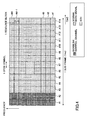
Fig. 6 illustrates a case where the data signals to which the transmission power control, in addition to the normal data signals, is applied are transmitted by one sub-frame. InFig. 6 , numbers (#1, #2, #3, ..., #14) in the time axis direction are numbers for identifying the OFDM symbols, and numbers (#1, #2, #3, ..., #M-1, #M, M is an integer more than 0) in the frequency axis direction are numbers for identifying resource blocks. InFig. 6 , the downlink control channels for LTE are mapped to the two beginning OFDM symbols of one sub-frame. In this case, the data signals to which the transmission power control is applied are transmitted by theresource block # 1 in theOFDM symbols # 3 through #14. The normal data signals are transmitted by areas other than the areas by which the downlink control channels are transmitted and the areas by which the data signals to which the transmission power control is applied are transmitted. InFig. 6 , although the data signals to which the transmission power control is applied are transmitted only by theresource block # 1, they may be transmitted by two or more resource blocks. - Next, the
base station apparatus 200 according to an example of the present invention is explained with reference toFig. 7 . - The
base station apparatus 200 according to this example includes a transmission/reception antenna 202, anamplification section 204, a transmission/reception section 206, a basebandsignal processing section 208, acall processing section 210, and atransmission path interface 212. - Packet data transmitted from the
base station apparatus 200 to the mobile station 100n in downlink are input to the basebandsignal processing section 208 from, for example, theaccess gateway apparatus 300 via thetransmission path interface 212. - In the baseband
signal processing section 208, the packet data undergoes segmentation/concatenation, Radio Link Control (RLC) layer transmission processing such as an RLC retransmission control, MAC retransmission control, transmission processing of, for example, Hybrid Automatic Repeat request (HARQ), scheduling, transmission format selection, channel coding, Inverse Fast Fourier Transform (IFFT) processing, and is forwarded to the transmission/reception section 206. In addition, the basebandsignal processing section 208 determines the transmission power levels assigned to the data signals to which the transmission power control is applied, the BCHs, the SCHs, the normal data signals, the Downlink Reference Signal and the like per sub-frame, resource block, and OFDM symbol, as described later. - In the transmission/
reception section 206, the baseband signal output from the basebandsignal processing section 208 undergoes frequency conversion processing for converting to a radio frequency band, is amplified by theamplification section 204, and is transmitted from the transmission/reception antenna 202. - On the other hand, regarding data transmitted from the mobile station apparatus 100n to the
base station apparatus 200 in uplink, the radio frequency band signals received by the transmission/reception antenna 202 are amplified by theamplification section 204, frequency-converted into a baseband signal by the transmission/reception section 206, and input to the basebandsignal processing section 208. - In the baseband
signal processing section 208, the input baseband signal undergoes FFT processing, IDFT processing, error correction decoding, reception processing of the MAC retransmission control, reception processing of RLC layer, and is forwarded to theaccess gateway apparatus 300 via thetransmission path interface 212. - The
call processing section 210 carries out resource assignment and state management of theradio station 200. - Next, a configuration of the baseband
signal processing section 208 is explained with reference toFig. 8 . - The baseband
signal processing section 208 includes alayer 1processing section 2081, a Medium Access Control (MAC)processing section 2082, anRLC processing section 2083, and a DL transmissionpower determining section 2084. - The
layer 1processing section 2081, theMAC processing section 2082, theRLC processing section 2083, and the DL transmissionpower determining section 2084 in the basebandsignal processing section 208, and thecall processing section 210 are connected with one another. - The
layer 1processing section 2081 carries out channel coding of the data transmitted in downlink, IFFT processing, channel decoding of the data transmitted in uplink, FFT processing and the like. In addition, thelayer 1processing section 2081 sets the transmission power levels of the sub-carriers to which the data signals where the transmission power control is applied, the BCHs, the SCHs, the normal data signals, the Downlink Reference Signals and the like are mapped, in accordance with the transmission power information provided from the DL transmissionpower determining section 2084. - The
MAC processing section 2082 carries out the downlink data MAC retransmission control, transmission processing of, for example, the Hybrid Automatic Repeat reQuest (HARQ), scheduling, transmission format selection, frequency resource assignment and the like. Here, the scheduling means a process for selecting a mobile station apparatus to which the normal data signal is transmitted in the sub-frame using the shared channel. As an algorithm for the scheduling, there are round robin and proportional fairness, for example. In addition, the transmission format selection means that a modulation scheme, a coding rate, and a data size regarding the normal data signal to be transmitted to the mobile station selected by the scheduling are determined. The modulation scheme, the coding rate, and the data size are determined in accordance with, for example, the CQI provided in uplink from the mobile station apparatus 100n. Moreover, the frequency resource assignment means a process for determining a resource block to be used to transmit the normal data signal to be transmitted to the mobile station apparatus selected by the scheduling. The resource block is determined in accordance with, for example, the CQI provided in uplink from the mobile station apparatus. - In addition, the
MAC processing section 2082 carries out the reception processing of MAC retransmission control, the scheduling, the transmission format selection, the frequency resource assignment and the like for uplink. - Moreover, an assignable
resource determining section 20821 in theMAC processing section 2082 determines resource blocks assignable to the normal data signal, in accordance with the transmission power information provided from the DL transmissionpower determining section 2084. TheMAC processing section 2082 carries out the scheduling, the transmission format selection, and the frequency resource assignment for the resource blocks assignable to the normal data signal. - For example, the assignable
resource determining section 20821 in theMAC processing section 2082 receives the transmission power level PBCH of the BCH in the sub-frame, the transmission power level PSCH of the SCH in the sub-frame, the transmission power level Pdata,TPC of the data signal to which the transmission power control is applied in the sub-frame, the transmission power level Pdata (unit) of the normal data signal per sub-carrier, and the maximum transmission power level Ptotal of thebase station apparatus 200 as the transmission power information from the DL transmissionpower determining section 2084, and calculates the number NumRB (data) of the resource blocks assignable to the normal data signal using the following expression (1).
- "12" in the expression (1) is the number of sub-carriers in one resource block. In addition, the following notation (2) means that a number inside the notation is rounded down to an integer (or fractions are omitted).
-

- The above calculation is carried out with PBCH = 0 and PSCH = 0 in the sub-frames by which the SCH and the BCH are not transmitted. In addition, when there are plural data signals to which the transmission power control is applied, the Pdata,TPC is a total of the transmission power levels of all the data signals to which the transmission power control is applied. When the NumRB (data) becomes greater than M, the NumRB (data) is made equal to M.
- Alternatively, when both the SCH and the BCH are transmitted in the sub-frame and by the same resource block (for example,
Fig. 5 ), the number NumRB (data) of the resource blocks assignable to the normal data signal may be calculated using the following expression (3), because only a higher one of the transmission power of the SCH and the transmission power of the BCH may be considered. Here, max(x, y) is a function that returns a larger value of x and y.
- In the above example, while the SCH, the BCH, the data signal to which the transmission power control is applied, and the normal data signal are exemplified as channels transmitted in the sub-frame, the number of the resource blocks assignable to the normal data signal can be calculated in the same manner when the other channels are transmitted.
- For example, when the SCH, the BCH, the data signal to which the transmission power control is applied, a Dynamic BCH, a paging channel PCH, a random access channel response RACH response, a channel for MBMS, and the normal data signal are transmitted as the channel transmitted in the sub-frame, the number NumRB (data) of the resource blocks assignable to the normal data signal may be calculated using the following expression (4).

- PD-BCH: transmission power of the Dynamic BCH in the sub-frame
- PPCH: transmission power of the PCH in the sub-frame
- PRACHres: transmission power of the RACH response
- PMBMS: transmission power of the channel for MBMS in the sub-frame
- Referring to
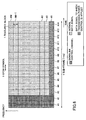
Fig. 9 , a more specific example is explained.Fig. 9 illustrates that transmission is turned off in one resource block in an example of the present invention. InFig. 9 , numbers (#1, #2, #3, ..., #14) in a time axis direction are numbers for identifying the OFDM symbols, and numbers (#1, #2, #3, ..., #M-1, #M; M is an integer more than 0) in a frequency axis direction are numbers for identifying resource blocks. InFig. 9 , the downlink control channels for LTE are mapped to two beginning OFDM symbols of one sub-frame. InFig. 9 , the data signals to which the transmission power control is applied are transmitted by theresource block # 1 in theOFDM symbols # 3 through #14, and the normal data signals are transmitted by areas other than the areas by which the downlink control channels for LTE are transmitted and the areas by which the data signals to which the transmission power control is applied are transmitted. At this time, PSCH is equal to 0 and PBCH is equal to 0. In addition, the number NumRB (data) is calculated to be M - 2 when Pdata,TPC = 24 x Pdata (unit), and Ptotal = 12 x M x Pdata (unit). At this time, the assignableresource determining section 20821 in theMAC processing section 2082 determines the resource blocks to be used to transmit the normal data signal to be the resource blocks #2 through #M-1, and turns off (or does not transmit) the resource block #M. Namely, the assignableresource determining section 20821 in theMAC processing section 2082 decreases the frequency resources (the number of resource blocks) to be assigned to the normal data signals when the transmission power of the data signals to which the transmission power control is applied is high, in order to keep the transmission power of the normal data signal constant. - For example, the assignable
resource determining section 20821 in theMAC processing section 2082 determines the frequency resources to be assigned to the normal data signal such that the frequency resources to be assigned to the normal data signal are decreased as the transmission power of the data signal to which the transmission power control is applied is increased. - In the above example, the resource block where the transmission is turned off is determined to be the resource block #M, but may be determined to be other resource blocks.
- The
RLC processing section 2083 carries out RLC layer transmission processing regarding the downlink packet data such as segmentation/concatenation, transmission processing of the RLC retransmission control and the like, and RLC layer reception processing regarding the uplink data such as segmentation/concatenation, the RLC retransmission control, and the like. - The DL transmission
power determining section 2084 determines the transmission power levels of the Downlink Reference Signal, the normal data signal, the SCH, the BCH, the data signal to which the transmission power control is applied and the like, and provides the determined transmission power levels of the Downlink Reference Signal, the normal data signal, the SCH, the BCH, the data signal to which the transmission power control is applied and the like to thelayer 1processing section 2081, theMAC processing section 2082, and especially, the assignableresource determining section 20821 in theMAC processing section 2082. Here, the transmission power values of the Downlink Reference Signal, the SCH, and the BCH are generally fixed values and determined in reference to a value signaled from the upper layer, or a value set as an internal parameter in thebase station apparatus 200. In addition, the transmission power of the data signal to which the transmission power control is applied is determined in accordance with, for example, the CQI value provided from the mobile station. Moreover, the transmission power per sub-carrier of the normal data signal may be set as, for example, the transmission power per sub-carrier when the transmission power is evenly assigned to all the sub-carriers in the system bandwidth. For example, when the number of the sub-carriers in the system bandwidth is 300, and the maximum transmission power of thebase station apparatus 200 is 20 W, the transmission power Pdata (unit) is calculated using the following expression.
- The transmission power value in the transmission power information may be the transmission power per sub-carrier, or a total transmission power of the sub-carriers to which the channel is mapped.
- In addition, the DL transmission
power determining section 2084 may provide thelayer 1processing section 2081 and theMAC processing section 2082 with the maximum transmission power (rated power) of thebase station apparatus 200 as part of the transmission power information. - Next, a communications control method in the
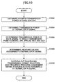
base station apparatus 200 according to this example is explained with reference toFig. 10 . - The DL transmission
power determining section 2084 obtains the maximum transmission power of thebase station apparatus 200, namely the rated power Ptotal (step S1002). - The DL transmission
power determining section 2084 obtains the transmission power per sub-carrier of the normal data signal Pdata (unit) (step S1004). Here, the transmission power per sub-carrier of the normal data signal may be the transmission power per sub-carrier when the transmission power is evenly assigned to all the sub-carriers in the system bandwidth. - The DL transmission power determining section 2085 determines the transmission power PBCH of the BCH, the transmission power PSCH of the SCH, and the transmission power Pdata,TPC of the data signal to which the transmission power control is applied (step S1006). Here, the transmission power of the data signal to which the transmission power control is applied is determined in accordance with, for example, the CQI value provided from the mobile station.
- The assignable
resource determining section 20821 in theMAC processing section 2082 determines resource blocks assignable to the normal data signal (step S1008). Here, the number NumRB (data) of the resource blocks assignable to the normal data signal is calculated using the following expression (5).
- The
MAC processing section 2082 carries out the scheduling, the transmission format selection, and the frequency resource assignment in the resource blocks assignable to the normal data signal (step S1010). - In the example described above, the normal data signal corresponds to a first signal, whereas the BCH, the SCH and the data signal to which the transmission power control is applied correspond to a second signal.
- In addition, although the BCH, the SCH and the data signal to which the transmission power control is applied correspond to the second signal in the example described above, the PCH and the RACH response may correspond to the second signal, instead.
- Moreover, the normal data signal may be a data signal to which Dynamic Scheduling is applied, and the data signal to which the transmission power control may be applied is a data signal to which Persistent Scheduling is applied.
- When the Persistent Scheduling is applied, the transmission power control is carried out at predetermined periods, and changed when necessary (when the transmission power needs to be changed). Namely, the transmission power is changed in terms of time when necessary. Here, the data signal to which the Dynamic Scheduling is applied is a data signal to which normal scheduling, for example, the frequency scheduling is applied.
- For example, the data signal is a downlink shared channel as a transport channel, and a dedicated traffic channel as a logical channel.
- In addition, although the rated power is used as the maximum transmission power of the base station apparatus, but may be a fixed value smaller than the rated power, instead.
- According to an example of the present invention, a base station apparatus and a communications control method that are capable of making constant transmission power per sub-carrier of the normal data signal, and utilizing the transmission power resources of the base station apparatus to a maximum even when there is a channel whose transmission power fluctuates with time.
- The above example is explained taking an example of the system where Evolved UTRA and UTRAN (another name: Long Term Evolution, or Super 3G) is applied. However, the base station apparatus and the communications control method according to an example of the present invention are applicable to other systems employing Orthogonal Frequency Division Multiple Access in downlink.
- While the present invention is described through the above examples, it should be understood that description and drawings as parts of this disclosure do not limit the present invention. Various alternative embodiments, examples and operational technologies are apparent to a person having ordinary skill in the art from the disclosure.
- In other words, the present invention includes various other embodiments that are not described here. Therefore, the technical scope of the present invention should be understood by matters necessary to specify the invention according to the Claims in conjunction with the above examples.
- While the present invention has been described separately as individual examples for simplicity of explanation, the individualities are not essential to the present invention, and one or more of the examples may be practiced when necessary. In addition, while the present invention has been described by using specific values in order to facilitate the understanding of the present invention, those values are merely examples and various values may be used unless otherwise noted.
- While the present invention has been explained with reference to specific examples, each example is merely illustrative and a person having ordinary skill will understand various alterations, modifications, substitutions, replacements and the like. While the apparatuses according to the examples of the present invention are explained in the form of the operational block diagrams for simplicity of explanation, such apparatuses may be realized by hardware, software or a combination thereof. The present invention is not limited to the above examples, but includes various alterations, modifications, substitutions, replacements and the like without departing the scope of the present invention.
- This international application claims the benefit of the priority date of Japanese Patent Application No.
2007-005196 filed on January 12, 2007 2007-005196 - A mobile communications system, a base station, a mobile station, and a communications control method according to embodiments of the present invention are applicable to a radio communications system.
Claims (8)
- A base station apparatus for carrying out communications with a mobile station in downlink using an OFDM method, the base station apparatus being characterized in that:the base station apparatus transmits a first signal and a second signal;a predetermined transmission power of the second signal is set; andthe base station apparatus comprisesa first transmission power controlling section that controls so that a transmission power per unit frequency band of the first signal is constant; anda frequency resource assignment section that determines a frequency resource to be assigned to the first signal, in accordance with the transmission power of the second signal and the transmission power per unit frequency band of the first signal.
- A base station apparatus for carrying out communications with a mobile station in downlink using an OFDM method, the base station apparatus being characterized in that:the base station apparatus transmits a first signal and a second signal; andthe base station apparatus comprisesa first transmission power controlling section that controls so that a transmission power per unit frequency band of the first signal is constant,a second transmission power controlling section that changes a transmission power of the second signal in terms of time, anda frequency resource assignment section that determines a frequency resource to be assigned to the first signal, in accordance with the transmission power of the second signal and the transmission power per unit frequency band of the first signal.
- The base station apparatus as claimed in claim 1 or 2, characterized in that the frequency resource assignment section determines the frequency resource to be assigned to the first signal so that the frequency resource to be assigned to the first signal is reduced as the transmission power of the second signal is increased.
- The base station apparatus as claimed in claim 1 or 2, characterized in that the first transmission power controlling section makes the transmission power per unit frequency band of the first signal a transmission power per unit frequency band obtained when a transmission power is evenly assigned to all of a frequency band.
- The base station apparatus as claimed in claim 1 or 2, characterized in that the frequency resource assignment section determines the frequency resource to be assigned to the first signal, in accordance with a maximum transmission power of the base station apparatus in addition to the transmission power of the second signal and the transmission power per unit frequency band of the first signal.
- The base station apparatus as claimed in claim 5, characterized in that the frequency resource assignment section determines a frequency resource BW1 to be assigned to the first signal in accordance with:

wherein,P1 (unit) is the transmission power per unit frequency band of the first signal,P2 is the transmission power of the second signal, andPtotal is a total transmission power. - The base station apparatus as claimed in any one of claims 1 through 6, characterized in that:the first signal is a channel to which dynamic scheduling is applied;the second signal is at least one of a broadcast channel, a synchronization channel, a channel to which persistent scheduling is applied, and a channel for MBMS.
- A communications control method in a base station apparatus for carrying out communications with a mobile station in downlink using an OFDM method, the communications control method being characterized in that:the base station apparatus transmits a first signal and a second signal, andthe communications control method comprisesa transmission power setting step, wherein a predetermined transmission power of the second signal is set;a first transmission power controlling step, wherein the transmission power per unit frequency band of the first signal is controlled to be constant; anda frequency resource assigning step, wherein the frequency resource to be assigned to the first signal is determined in accordance with the transmission power of the second signal and the transmission power per unit frequency band of the first signal.
Applications Claiming Priority (2)
| Application Number | Priority Date | Filing Date | Title |
|---|---|---|---|
| JP2007005196 | 2007-01-12 | ||
| PCT/JP2007/073979 WO2008084623A1 (en) | 2007-01-12 | 2007-12-12 | Base station device and communication control method |
Publications (2)
| Publication Number | Publication Date |
|---|---|
| EP2120473A1 true EP2120473A1 (en) | 2009-11-18 |
| EP2120473A4 EP2120473A4 (en) | 2014-01-01 |
Family
ID=39608522
Family Applications (1)
| Application Number | Title | Priority Date | Filing Date |
|---|---|---|---|
| EP07859797.8A Withdrawn EP2120473A4 (en) | 2007-01-12 | 2007-12-12 | Base station device and communication control method |
Country Status (6)
| Country | Link |
|---|---|
| US (1) | US8249634B2 (en) |
| EP (1) | EP2120473A4 (en) |
| JP (1) | JP5468267B2 (en) |
| KR (1) | KR20090098989A (en) |
| CN (1) | CN101578903B (en) |
| WO (1) | WO2008084623A1 (en) |
Cited By (3)
| Publication number | Priority date | Publication date | Assignee | Title |
|---|---|---|---|---|
| WO2011079849A1 (en) * | 2009-12-29 | 2011-07-07 | Telecom Italia S.P.A. . | Adaptive scheduling data transmission based on the transmission power and the number of physical resource blocks |
| EP2900020A1 (en) * | 2009-10-27 | 2015-07-29 | Huawei Technologies Co., Ltd. | Power-saving method and system |
| KR20210048324A (en) | 2019-10-23 | 2021-05-03 | 주식회사 만도 | Electric brake system and control method thereof |
Families Citing this family (9)
| Publication number | Priority date | Publication date | Assignee | Title |
|---|---|---|---|---|
| GB0807338D0 (en) * | 2008-04-22 | 2008-05-28 | Nokia Siemens Networks Oy | An apparatus |
| US20120021798A1 (en) * | 2009-01-26 | 2012-01-26 | Nec Corporation | Communication device and its transmission power control method in radio communications system |
| KR101641119B1 (en) | 2009-02-02 | 2016-07-20 | 삼성전자 주식회사 | Method of receaving and transmssion control channel in a wireless comunication system and an apparatus thereof |
| JP5531767B2 (en) | 2009-07-31 | 2014-06-25 | ソニー株式会社 | Transmission power control method, communication apparatus, and program |
| JP5565082B2 (en) | 2009-07-31 | 2014-08-06 | ソニー株式会社 | Transmission power determination method, communication apparatus, and program |
| JP5297317B2 (en) * | 2009-09-16 | 2013-09-25 | Kddi株式会社 | Radio resource allocation device and radio resource allocation method |
| JP5423499B2 (en) | 2010-03-16 | 2014-02-19 | 富士通株式会社 | Base station apparatus, communication system, and communication system control method |
| CN103686746A (en) * | 2012-09-06 | 2014-03-26 | 华为技术有限公司 | Method, device and base station for device discovery signal transmission |
| JP6256024B2 (en) * | 2014-01-16 | 2018-01-10 | 富士通株式会社 | Radio base station and radio base station transmission power control method |
Family Cites Families (17)
| Publication number | Priority date | Publication date | Assignee | Title |
|---|---|---|---|---|
| JP3630629B2 (en) * | 1999-10-28 | 2005-03-16 | ユーティースターコム コリア リミテッド | Asynchronous mobile communication system |
| EP1238551B1 (en) * | 1999-12-01 | 2006-02-08 | Robert Bosch Gmbh | Method for allocating transmission channels in a telecommunications network and subscriber station |
| BRPI0512977A (en) | 2004-07-06 | 2008-04-22 | Matsushita Electric Ind Co Ltd | multi-carrier transmission device and multi-carrier transmission method |
| JPWO2006043588A1 (en) | 2004-10-19 | 2008-05-22 | シャープ株式会社 | Base station apparatus, radio communication system, and radio transmission method |
| JP4334485B2 (en) * | 2005-02-04 | 2009-09-30 | シャープ株式会社 | Control station apparatus, terminal apparatus, and scheduling method |
| JP4632245B2 (en) | 2005-02-23 | 2011-02-16 | 株式会社エヌ・ティ・ティ・ドコモ | Transmitting station, mobile communication system, and transmission power control method |
| JP2007221178A (en) | 2005-04-01 | 2007-08-30 | Ntt Docomo Inc | Transmitting apparatus and method |
| WO2006112133A1 (en) * | 2005-04-08 | 2006-10-26 | Sharp Kabushiki Kaisha | Wireless transmitter and wireless communication system |
| CN101185263A (en) | 2005-05-26 | 2008-05-21 | 松下电器产业株式会社 | Wireless communication base station apparatus and wireless communication method |
| JP4671771B2 (en) | 2005-06-10 | 2011-04-20 | 株式会社エヌ・ティ・ティ・ドコモ | Wireless communication apparatus and wireless communication method |
| JP2007005196A (en) | 2005-06-24 | 2007-01-11 | Hitachi Maxell Ltd | Alkaline battery |
| CN101331693A (en) * | 2005-10-17 | 2008-12-24 | 日本电气株式会社 | Radio communication method, radio communication system, base station, and mobile station |
| KR101319870B1 (en) * | 2006-01-05 | 2013-10-18 | 엘지전자 주식회사 | Method for handover in mobile communication system |
| EP1871125B1 (en) * | 2006-06-20 | 2013-10-23 | Nokia Siemens Networks GmbH & Co. KG | Efficient radio resource management in a mobile communication system |
| US8335233B2 (en) * | 2007-03-01 | 2012-12-18 | Ntt Docomo, Inc. | Base station apparatus and communication control method using an uplink shared channel |
| JPWO2008108228A1 (en) * | 2007-03-01 | 2010-06-10 | 株式会社エヌ・ティ・ティ・ドコモ | Base station apparatus and communication control method |
| JP5169689B2 (en) * | 2008-02-14 | 2013-03-27 | 富士通株式会社 | Communication device |
-
2007
- 2007-12-12 KR KR1020097015445A patent/KR20090098989A/en not_active Application Discontinuation
- 2007-12-12 WO PCT/JP2007/073979 patent/WO2008084623A1/en active Application Filing
- 2007-12-12 JP JP2008553034A patent/JP5468267B2/en active Active
- 2007-12-12 CN CN2007800495159A patent/CN101578903B/en not_active Expired - Fee Related
- 2007-12-12 US US12/522,393 patent/US8249634B2/en not_active Expired - Fee Related
- 2007-12-12 EP EP07859797.8A patent/EP2120473A4/en not_active Withdrawn
Non-Patent Citations (4)
| Title |
|---|
| LG ELECTRONICS: "Downlink transmit power boosting", 3GPP DRAFT; R1-070250 - DL POWER BOOSTING, 3RD GENERATION PARTNERSHIP PROJECT (3GPP), MOBILE COMPETENCE CENTRE ; 650, ROUTE DES LUCIOLES ; F-06921 SOPHIA-ANTIPOLIS CEDEX ; FRANCE, vol. RAN WG1, no. Sorrento, Italy; 20070110, 10 January 2007 (2007-01-10), XP050104288, [retrieved on 2007-01-10] * |
| NTT DOCOMO ET AL: "Power Boosting of Reference Signal in E-UTRA Downlink", 3GPP DRAFT; R1-070088 POWER BOOSTING OF DL REFERENCE SIGNAL, 3RD GENERATION PARTNERSHIP PROJECT (3GPP), MOBILE COMPETENCE CENTRE ; 650, ROUTE DES LUCIOLES ; F-06921 SOPHIA-ANTIPOLIS CEDEX ; FRANCE, vol. RAN WG1, no. Sorrento, Italy; 20070110, 10 January 2007 (2007-01-10), XP050104140, [retrieved on 2007-01-10] * |
| NTT DOCOMO ET AL: "Transmission Power Control in E-UTRA Downlink", 3GPP DRAFT; R1-070107 DL TRANSMISSION POWER CONTROL, 3RD GENERATION PARTNERSHIP PROJECT (3GPP), MOBILE COMPETENCE CENTRE ; 650, ROUTE DES LUCIOLES ; F-06921 SOPHIA-ANTIPOLIS CEDEX ; FRANCE, vol. RAN WG1, no. Sorrento, Italy; 20070110, 10 January 2007 (2007-01-10), XP050104156, [retrieved on 2007-01-10] * |
| See also references of WO2008084623A1 * |
Cited By (4)
| Publication number | Priority date | Publication date | Assignee | Title |
|---|---|---|---|---|
| EP2900020A1 (en) * | 2009-10-27 | 2015-07-29 | Huawei Technologies Co., Ltd. | Power-saving method and system |
| WO2011079849A1 (en) * | 2009-12-29 | 2011-07-07 | Telecom Italia S.P.A. . | Adaptive scheduling data transmission based on the transmission power and the number of physical resource blocks |
| US8824406B2 (en) | 2009-12-29 | 2014-09-02 | Telecom Italia S.P.A. | Adaptive scheduling data transmission based on the transmission power and the number of physical resource blocks |
| KR20210048324A (en) | 2019-10-23 | 2021-05-03 | 주식회사 만도 | Electric brake system and control method thereof |
Also Published As
| Publication number | Publication date |
|---|---|
| US20100113080A1 (en) | 2010-05-06 |
| US8249634B2 (en) | 2012-08-21 |
| CN101578903A (en) | 2009-11-11 |
| JPWO2008084623A1 (en) | 2010-04-30 |
| EP2120473A4 (en) | 2014-01-01 |
| WO2008084623A1 (en) | 2008-07-17 |
| JP5468267B2 (en) | 2014-04-09 |
| KR20090098989A (en) | 2009-09-18 |
| CN101578903B (en) | 2012-07-18 |
Similar Documents
| Publication | Publication Date | Title |
|---|---|---|
| US8249634B2 (en) | Base station apparatus and communications control method | |
| EP2241049B1 (en) | Sounding reference signal arrangement | |
| US8780851B2 (en) | Base station apparatus, mobile station, radio communication system, and communication control method | |
| US8072918B2 (en) | Network-based inter-cell power control for multi-channel wireless networks | |
| US8559297B2 (en) | User apparatus, base station apparatus, and communication control method for controlling coverage area and data rate according to environments | |
| JP4672063B2 (en) | Mobile station, communication control method, and mobile communication system | |
| EP2120471A1 (en) | Base station device and communication control method | |
| KR20100139042A (en) | Frequency hopping pattern and arrangement for sounding reference signal | |
| KR20100088084A (en) | Method and apparatus of controlling transmission power | |
| EP2104254A1 (en) | Base station device and communication control method | |
| KR20110044890A (en) | Mobile communication system, transmitter, receiver and method | |
| EP2608597A1 (en) | Base station apparatus, mobile terminal apparatus and communication control method | |
| JP5052599B2 (en) | Delivery confirmation information transmission method, base station apparatus, and user apparatus | |
| CN107637004B (en) | Method of reporting channel state information and apparatus using the same | |
| EP2139244A1 (en) | User device, base station device, mobile communication system and communication control method | |
| AU2009203740B2 (en) | Sounding reference signal arrangement |
Legal Events
| Date | Code | Title | Description |
|---|---|---|---|
| PUAI | Public reference made under article 153(3) epc to a published international application that has entered the european phase |
Free format text: ORIGINAL CODE: 0009012 |
|
| 17P | Request for examination filed |
Effective date: 20090707 |
|
| AK | Designated contracting states |
Kind code of ref document: A1 Designated state(s): AT BE BG CH CY CZ DE DK EE ES FI FR GB GR HU IE IS IT LI LT LU LV MC MT NL PL PT RO SE SI SK TR |
|
| RIC1 | Information provided on ipc code assigned before grant |
Ipc: H04B 7/26 20060101ALI20091016BHEP Ipc: H04J 1/00 20060101ALI20091016BHEP Ipc: H04J 11/00 20060101ALI20091016BHEP Ipc: H04W 16/00 20090101AFI20091016BHEP |
|
| DAX | Request for extension of the european patent (deleted) | ||
| A4 | Supplementary search report drawn up and despatched |
Effective date: 20131128 |
|
| RIC1 | Information provided on ipc code assigned before grant |
Ipc: H04W 72/04 20090101AFI20131122BHEP Ipc: H04W 52/14 20090101ALN20131122BHEP Ipc: H04W 52/16 20090101ALN20131122BHEP |
|
| 17Q | First examination report despatched |
Effective date: 20180118 |
|
| GRAP | Despatch of communication of intention to grant a patent |
Free format text: ORIGINAL CODE: EPIDOSNIGR1 |
|
| RIC1 | Information provided on ipc code assigned before grant |
Ipc: H04L 1/18 20060101ALN20180830BHEP Ipc: H04L 1/00 20060101ALN20180830BHEP Ipc: H04L 5/00 20060101ALI20180830BHEP Ipc: H04W 52/16 20090101ALN20180830BHEP Ipc: H04W 72/04 20090101AFI20180830BHEP Ipc: H04W 52/14 20090101ALN20180830BHEP |
|
| INTG | Intention to grant announced |
Effective date: 20181004 |
|
| STAA | Information on the status of an ep patent application or granted ep patent |
Free format text: STATUS: THE APPLICATION IS DEEMED TO BE WITHDRAWN |
|
| 18D | Application deemed to be withdrawn |
Effective date: 20190215 |