EP2120373A1 - Receiving device for visible light communication, and visible light communication system - Google Patents
Receiving device for visible light communication, and visible light communication system Download PDFInfo
- Publication number
- EP2120373A1 EP2120373A1 EP08710661A EP08710661A EP2120373A1 EP 2120373 A1 EP2120373 A1 EP 2120373A1 EP 08710661 A EP08710661 A EP 08710661A EP 08710661 A EP08710661 A EP 08710661A EP 2120373 A1 EP2120373 A1 EP 2120373A1
- Authority
- EP
- European Patent Office
- Prior art keywords
- data
- illumination light
- receiver
- demodulating
- received
- Prior art date
- Legal status (The legal status is an assumption and is not a legal conclusion. Google has not performed a legal analysis and makes no representation as to the accuracy of the status listed.)
- Withdrawn
Links
Images




Classifications
-
- H—ELECTRICITY
- H04—ELECTRIC COMMUNICATION TECHNIQUE
- H04B—TRANSMISSION
- H04B10/00—Transmission systems employing electromagnetic waves other than radio-waves, e.g. infrared, visible or ultraviolet light, or employing corpuscular radiation, e.g. quantum communication
- H04B10/11—Arrangements specific to free-space transmission, i.e. transmission through air or vacuum
- H04B10/114—Indoor or close-range type systems
- H04B10/116—Visible light communication
-
- H—ELECTRICITY
- H04—ELECTRIC COMMUNICATION TECHNIQUE
- H04B—TRANSMISSION
- H04B10/00—Transmission systems employing electromagnetic waves other than radio-waves, e.g. infrared, visible or ultraviolet light, or employing corpuscular radiation, e.g. quantum communication
- H04B10/11—Arrangements specific to free-space transmission, i.e. transmission through air or vacuum
- H04B10/114—Indoor or close-range type systems
- H04B10/1149—Arrangements for indoor wireless networking of information
-
- H—ELECTRICITY
- H04—ELECTRIC COMMUNICATION TECHNIQUE
- H04B—TRANSMISSION
- H04B10/00—Transmission systems employing electromagnetic waves other than radio-waves, e.g. infrared, visible or ultraviolet light, or employing corpuscular radiation, e.g. quantum communication
- H04B10/60—Receivers
Definitions
- the present invention generally relates to a visible light communication system using visible light and, more particularly, to a visible light communication system for receiving visible light on a solar cell panel.
- Patent Document 1 a light emitting apparatus using an electro-luminescence device capable of emitting signal light formed of light modulated on the basis of input data is disclosed.
- Patent Document 1 the power needs to be supplied to a receiver.
- employment of a plurality of transmitters which synchronize data is difficult.
- the present invention has been accomplished to solve the above-described problem.
- the object of the present invention is to provide a receiver and system for visible light communication in which supply of the power to the receiver is unnecessary.
- an embodiment of the present invention provides a visible light communication system, comprising a data storage apparatus, a data transmitter and a data receiver, the data transmitter comprises data receiving means for receiving data from the data storage apparatus; modulating means for modulating the data received by the data receiving means; and transmitting means for transmitting the data modulated by the modulating means to the data receiver as a carrier of illumination light, and the data receiver comprises illumination light detecting means for detecting the illumination light received by the transmitting means in accordance with an output variation of power converting means; demodulating means for demodulating the illumination light detected by the illumination light detecting means; and displaying means for displaying the data demodulated by the demodulating means.
- an embodiment of the present invention provides a receiver of visible light communication, comprising illumination light detecting means for detecting modulated data in accordance with an output variation of power converting means, demodulating means for demodulating the illumination light detected by the illumination light detecting means, and displaying means for displaying the data demodulated by the demodulating means.
- a visible light communication system to transmit data with illumination light from an illuminating device for LED illumination or the like, data digital- or analog-modulated with a subcarrier are output with the illumination light serving as a carrier.
- the illumination light which carries the data is invisible to a human eye.
- the data are transmitted in a state which is apparently the same as that of the other general illumination.
- a receiving-side apparatus comprises a solar cell panel, and can obtain power from the solar cell panel by receiving the illumination light on the solar cell panel. The power is supplied as a power source of the receiving-side apparatus.
- the transmitted data can be obtained by extracting the modulated data carried by the illumination light from output variation waveforms of voltage and current from the solar cell panel and modulating the data.
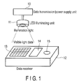
- the visible light communication system is composed of a transmitter for visible light communication and a receiver 12 for visible light communication.
- the transmitter comprises a data transmission/power supply unit 10 and an LED (Light Emitting Diode) illuminating unit 11. Illumination light is applied from the LED illuminating unit 11.
- the receiver 12 comprises a solar cell panel 13, a display unit 14, a speech generating unit 15 and the like.
- the LED is used as the illuminating device.
- the illuminating device is not limited to the LED, but may also be visible light.
- FIG. 2 is a block diagram showing the visible light communication system according to the embodiment of the present invention.
- the data transmission/power supply unit 10 comprises a data modulating unit 20, a transmit data generating unit 21, an LED driving unit 22, a power supply unit 23 and the LED illuminating unit 11.
- a driving power supply for the LED illumination is generated, and transmit data are generated from predetermined data.
- the data are digital- or analog-modulated with a subcarrier at a transmission timing and output to the LED illumination together with the modulated data by the LED driving unit.
- the power supply unit 23 receives the power and data from a data management apparatus (data storage apparatus) 41 (see FIG. 8 ) to be described later via a power line 43 (see FIG. 8 ).
- the transmit data generating unit 21 generates the transmit data from the received data.
- the transmit data generating unit 21 generates data to transmit the data predetermined by setting, writing and the like.
- the data modulating unit 20 modulates the generated data and transmits the modulated data to the LED driving unit 22.
- the data modulating unit 20 digital- or analog-modulates the data with the subcarrier at the transmission timing.
- the LED driving unit 22 executes the control to output the illumination light from the LED illuminating unit 11 on the basis of the modulated data.
- the receiver 12 comprises the solar cell panel 13, a power storage unit 16, a power supply unit 17, a waveform extracting unit 18, a signal modulating unit 19, the display unit 14, and the speech generating unit 15.
- the solar cell panel 13 receives the illumination light and generates the power.
- the power storage unit 16 is a storage battery which stores the power generated by the solar cell panel 13, or a capacitor or secondary battery which stores a certain quantity of the power.
- the power supply unit 17 supplies the power from the power storage unit 16 to an inner circuit. In other words, the power supply unit 17 stabilizes the power and supplies the stabilized power to each of the units in the receiving-side apparatus.
- the waveform extracting unit 18 receives the light from the solar cell panel 13 and detects output variation of the generated power.
- the signal modulating unit 19 separates the modulated data from the illumination light received by the solar cell panel 13 and demodulates the separated data.
- the signal modulating unit 19 can obtain the data modulated by the subcarrier transmitted from the transmitting side, by capturing an output waveform variation of the output voltage or current or the like of the solar cell panel 13 which receives the illumination light including the data.
- the display unit 14 displays the data demodulated by the signal modulating unit 19. In other words, when the data transmitted from the transmitting side are data such as letters and characters, pictures, images and the like, the data are displayed by the display unit.
- the speech generating unit 15 executing outputting when the demodulated data are speech, music and the like.
- Data are transmitted to the data transmission/power supply unit 10 of the transmitter via the power line 43 by the data management apparatus 41.
- the power supply unit 23 of the data transmission/power supply unit 10 receives the data transmitted via the power line and transmits the data to the transmit data generating unit 21.
- the transmit data generating unit 21 generates transmit data (step S101).
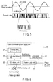
- the data modulating unit 20 detects a zero cross point of an AC power supply via the power line (step S102). As for the detection of the zero cross point, for example, an AC power supply waveform to be supplied to the transmitter (a point where the AC power supply waveform is zero) is detected as the zero cross point as shown in FIG. 5 .
- the data modulating unit 20 modulates the data by using the zero cross point as a trigger (step S103). After the data are digital- or analog-modulated with the subcarrier, the illumination light is output to the LED illuminating unit 11 together with the modulated data by the LED driving unit 22 (step S104).
- FIG. 4 is an illumination showing a structure in a case where a plurality of transmitters are arranged.
- a plurality of transmitters are arranged at adjacent positions where the illumination light causes interference.
- FIG. 6 is a block diagram showing a structure of the transmitter in a case where plurality of transmitters are arranged.
- the transmitter is different from that shown in FIG. 2 in terms of comprising a zero cross detecting unit 24.
- a zero cross detecting unit 24 By transmitting information of the zero cross point detected by the zero cross detecting unit 24 to the data modulating unit 20, synchronization of the data transmission is made.
- the data transmitted from a plurality of transmitters at the adjacent positions where the illumination light causes interference can be synchronized and output by detecting the zero cross point where the AC power supply waveform crosses 0V and outputting from the LED illumination the transmit data of each frame transmitted from the transmitter with the distribution of the zero cross point used as the synchronous signal.
- the power is supplied to a plurality of transmitters by the AC power supply of AC 100V or the like (power line 43) and the driving power supply of the LED illumination is generated with the supplied power.
- the transmit data are generated with data which are predetermined by setting, writing and the like, the zero cross point in the AC power supply waveform where the power is supplied to the transmitter is detected as transmission timing of the generated data, the data are digital- or analog-modulated with the subcarrier by using the calculated zero cross point as the trigger, and the illumination light is output to the LED illumination together with the modulated data by the LED driving unit.
- the receiver 12 can receive the data while freely moving under a plurality of illuminations.
- the data are received from the data management apparatus 41 not via the power line 43, but the power line carrier modem 25.
- the power line carrier modem 25 receives the power line carrier communication data carried by the AC power supply supplied to the transmitters. For this reason, since the data reception from the host side (data management apparatus 41) and synchronization of the transmission timings of a plurality of transmitters both can be executed by the AC power supply supplied to the transmitters, the communication apparatus which does not require cables for communication and synchronization except the cables for the power supply and which uses a plurality of illuminations for variable transmit data can be implemented.
- FIG. 8 is an illustration showing a structure in a case where a plurality of transmitters are arranged together at specific positions. These transmitters A-1 to A-6 are connected by the AC power supply (power line 43) for supplying the power.
- the AC power is supplied from a distribution switchboard 40 which serves as a power supplier, and connected to the data management apparatus 41 via a power line carrier modem 42, such that the transmit data are transmitted from the data management apparatus 41 to the transmitters A-1 to A-6 using the LED illuminations by the power line carrier data communication.
- the transmitted data are output as the illumination light from the LED illuminations and transmitted to the receiver 12.
- the same data can be transmitted to a number of transmitters A-1 to A-6 without interference. Since the transmitters A-1 to A-6 temporarily store and modulate the data transmitted from the data management apparatus 41 and then transmit the data to the receiver 12 as the LED illuminations, short time lag occurs. For this reason, the data are not transmitted via the power line 43 at a real time.
- the solar cell panel is used as the received light of the illumination light and the supply of the power is also executed at the receiver side, the receiver can be employed without a power source. Even if a plurality of transmitters are arranged, exact data communication can be executed without interference.
- the present invention is not limited to the embodiments described above but the constituent elements of the invention can be modified in various manners without departing from the spirit and scope of the invention.
- Various aspects of the invention can also be extracted from any appropriate combination of a plurality of constituent elements disclosed in the embodiments. Some constituent elements may be deleted in all of the constituent elements disclosed in the embodiments. The constituent elements described in different embodiments may be combined arbitrarily.
- a receiver and system for visible light communication in which supply of the power to the receiver is unnecessary can be provided.
Landscapes
- Engineering & Computer Science (AREA)
- Physics & Mathematics (AREA)
- Electromagnetism (AREA)
- Computer Networks & Wireless Communication (AREA)
- Signal Processing (AREA)
- Computing Systems (AREA)
- Optical Communication System (AREA)
- Cable Transmission Systems, Equalization Of Radio And Reduction Of Echo (AREA)
Abstract
Description
- The present invention generally relates to a visible light communication system using visible light and, more particularly, to a visible light communication system for receiving visible light on a solar cell panel.
- Generally, in the communication technology using visible light, a light emitting apparatus using an electro-luminescence device capable of emitting signal light formed of light modulated on the basis of input data is disclosed (see Patent Document 1).
- Patent Document 1: Jpn. Pat. Appln. KOKAI Publication No.
2003-115803 - According to the technology disclosed in
Patent Document 1, however, the power needs to be supplied to a receiver. In addition, employment of a plurality of transmitters which synchronize data is difficult. - The present invention has been accomplished to solve the above-described problem. The object of the present invention is to provide a receiver and system for visible light communication in which supply of the power to the receiver is unnecessary.
- To achieve the above-described object, an embodiment of the present invention provides a visible light communication system, comprising a data storage apparatus, a data transmitter and a data receiver, the data transmitter comprises data receiving means for receiving data from the data storage apparatus; modulating means for modulating the data received by the data receiving means; and transmitting means for transmitting the data modulated by the modulating means to the data receiver as a carrier of illumination light, and the data receiver comprises illumination light detecting means for detecting the illumination light received by the transmitting means in accordance with an output variation of power converting means; demodulating means for demodulating the illumination light detected by the illumination light detecting means; and displaying means for displaying the data demodulated by the demodulating means.
- Furthermore, an embodiment of the present invention provides a receiver of visible light communication, comprising illumination light detecting means for detecting modulated data in accordance with an output variation of power converting means, demodulating means for demodulating the illumination light detected by the illumination light detecting means, and displaying means for displaying the data demodulated by the demodulating means.
-
-
FIG. 1 is an illustration showing a visible light communication system according to an embodiment of the present invention. -
FIG. 2 is a block diagram showing the visible light communication system according to the embodiment of the present invention. -
FIG. 3 is a flowchart for explanation of the control of the visible light communication system receiver according to the embodiment of the present invention. -
FIG. 4 is an illustration showing a structure in a case of providing a plurality of transmitters according to the embodiment of the present invention. -
FIG. 5 is an illustration showing a zero cross point detecting method according to the embodiment of the present invention. -
FIG. 6 is a block diagram showing a structure of a transmitter in a case of providing a plurality of transmitters according to the embodiment of the present invention. -
FIG. 7 is a block diagram showing a structure in a case where a power line carrier modem is further added to the structure, according to the embodiment of the present invention. -
FIG. 8 is an illustration showing a structure in a case where a plurality of transmitters according to the embodiment of the present invention are arranged together at specific positions. - Embodiments of the present invention will be explained below with reference to the accompanying drawings.
- First, in a visible light communication system according to an embodiment of the present invention, to transmit data with illumination light from an illuminating device for LED illumination or the like, data digital- or analog-modulated with a subcarrier are output with the illumination light serving as a carrier. The illumination light which carries the data is invisible to a human eye. The data are transmitted in a state which is apparently the same as that of the other general illumination. A receiving-side apparatus comprises a solar cell panel, and can obtain power from the solar cell panel by receiving the illumination light on the solar cell panel. The power is supplied as a power source of the receiving-side apparatus. In addition, the transmitted data can be obtained by extracting the modulated data carried by the illumination light from output variation waveforms of voltage and current from the solar cell panel and modulating the data.
- As shown in
FIG. 1 , the visible light communication system according to the embodiment of the present invention is composed of a transmitter for visible light communication and areceiver 12 for visible light communication. The transmitter comprises a data transmission/power supply unit 10 and an LED (Light Emitting Diode) illuminatingunit 11. Illumination light is applied from the LEDilluminating unit 11. Thereceiver 12 comprises asolar cell panel 13, adisplay unit 14, aspeech generating unit 15 and the like. In the present embodiment, the LED is used as the illuminating device. However, the illuminating device is not limited to the LED, but may also be visible light. -
FIG. 2 is a block diagram showing the visible light communication system according to the embodiment of the present invention. - The visible light communication system according to the embodiment of the present invention will be described with reference to the block diagram. The data transmission/
power supply unit 10 comprises adata modulating unit 20, a transmitdata generating unit 21, anLED driving unit 22, apower supply unit 23 and the LEDilluminating unit 11. A driving power supply for the LED illumination is generated, and transmit data are generated from predetermined data. The data are digital- or analog-modulated with a subcarrier at a transmission timing and output to the LED illumination together with the modulated data by the LED driving unit. Thepower supply unit 23 receives the power and data from a data management apparatus (data storage apparatus) 41 (seeFIG. 8 ) to be described later via a power line 43 (seeFIG. 8 ). The transmitdata generating unit 21 generates the transmit data from the received data. In addition, the transmitdata generating unit 21 generates data to transmit the data predetermined by setting, writing and the like. - The
data modulating unit 20 modulates the generated data and transmits the modulated data to theLED driving unit 22. In addition, thedata modulating unit 20 digital- or analog-modulates the data with the subcarrier at the transmission timing. TheLED driving unit 22 executes the control to output the illumination light from theLED illuminating unit 11 on the basis of the modulated data. - The
receiver 12 comprises thesolar cell panel 13, apower storage unit 16, apower supply unit 17, awaveform extracting unit 18, asignal modulating unit 19, thedisplay unit 14, and thespeech generating unit 15. Thesolar cell panel 13 receives the illumination light and generates the power. Thepower storage unit 16 is a storage battery which stores the power generated by thesolar cell panel 13, or a capacitor or secondary battery which stores a certain quantity of the power. Thepower supply unit 17 supplies the power from thepower storage unit 16 to an inner circuit. In other words, thepower supply unit 17 stabilizes the power and supplies the stabilized power to each of the units in the receiving-side apparatus. Thewaveform extracting unit 18 receives the light from thesolar cell panel 13 and detects output variation of the generated power. Thesignal modulating unit 19 separates the modulated data from the illumination light received by thesolar cell panel 13 and demodulates the separated data. In addition, thesignal modulating unit 19 can obtain the data modulated by the subcarrier transmitted from the transmitting side, by capturing an output waveform variation of the output voltage or current or the like of thesolar cell panel 13 which receives the illumination light including the data. Thedisplay unit 14 displays the data demodulated by thesignal modulating unit 19. In other words, when the data transmitted from the transmitting side are data such as letters and characters, pictures, images and the like, the data are displayed by the display unit. Thespeech generating unit 15 executing outputting when the demodulated data are speech, music and the like. - Next, a method of controlling the visible light communication system and the receiver according to the embodiment of the present invention will be described with reference to a flowchart of
FIG. 3 . - Data are transmitted to the data transmission/
power supply unit 10 of the transmitter via thepower line 43 by thedata management apparatus 41. Thepower supply unit 23 of the data transmission/power supply unit 10 receives the data transmitted via the power line and transmits the data to the transmitdata generating unit 21. The transmitdata generating unit 21 generates transmit data (step S101). Thedata modulating unit 20 detects a zero cross point of an AC power supply via the power line (step S102). As for the detection of the zero cross point, for example, an AC power supply waveform to be supplied to the transmitter (a point where the AC power supply waveform is zero) is detected as the zero cross point as shown inFIG. 5 . Thedata modulating unit 20 modulates the data by using the zero cross point as a trigger (step S103). After the data are digital- or analog-modulated with the subcarrier, the illumination light is output to theLED illuminating unit 11 together with the modulated data by the LED driving unit 22 (step S104). - Next,
FIG. 4 is an illumination showing a structure in a case where a plurality of transmitters are arranged. - As shown in
FIG. 4 , a plurality of transmitters are arranged at adjacent positions where the illumination light causes interference. - In addition,
FIG. 6 is a block diagram showing a structure of the transmitter in a case where plurality of transmitters are arranged. - The transmitter is different from that shown in
FIG. 2 in terms of comprising a zerocross detecting unit 24. By transmitting information of the zero cross point detected by the zerocross detecting unit 24 to thedata modulating unit 20, synchronization of the data transmission is made. In other words, with the AC power supply waveform of AC100V, 50Hz/60Hz or the like supplied to the transmitter, the data transmitted from a plurality of transmitters at the adjacent positions where the illumination light causes interference can be synchronized and output by detecting the zero cross point where the AC power supply waveform crosses 0V and outputting from the LED illumination the transmit data of each frame transmitted from the transmitter with the distribution of the zero cross point used as the synchronous signal. - In a case where the data digital- or analog-modulated with the subcarrier are output by using the illumination light as the carrier to transmit data by using the illumination light from the LED illumination as the carrier, the power is supplied to a plurality of transmitters by the AC power supply of AC 100V or the like (power line 43) and the driving power supply of the LED illumination is generated with the supplied power. The transmit data are generated with data which are predetermined by setting, writing and the like, the zero cross point in the AC power supply waveform where the power is supplied to the transmitter is detected as transmission timing of the generated data, the data are digital- or analog-modulated with the subcarrier by using the calculated zero cross point as the trigger, and the illumination light is output to the LED illumination together with the modulated data by the LED driving unit.
- For this reason, even if the transmitters are arranged at adjacent positions where the illumination causes interference, the data can be received stably at the receiving side. Even if the receiver moves between the LED illuminations of the transmitters, the data can be received without interrupting the reception on the
receiver 12 side. In addition, thereceiver 12 can receive the data while freely moving under a plurality of illuminations. - In addition, in a case where a power
line carrier modem 25 is added to the structure as shown inFIG. 7 , the data are received from thedata management apparatus 41 not via thepower line 43, but the powerline carrier modem 25. In other words, the powerline carrier modem 25 receives the power line carrier communication data carried by the AC power supply supplied to the transmitters. For this reason, since the data reception from the host side (data management apparatus 41) and synchronization of the transmission timings of a plurality of transmitters both can be executed by the AC power supply supplied to the transmitters, the communication apparatus which does not require cables for communication and synchronization except the cables for the power supply and which uses a plurality of illuminations for variable transmit data can be implemented. - Next,
FIG. 8 is an illustration showing a structure in a case where a plurality of transmitters are arranged together at specific positions. These transmitters A-1 to A-6 are connected by the AC power supply (power line 43) for supplying the power. The AC power is supplied from adistribution switchboard 40 which serves as a power supplier, and connected to thedata management apparatus 41 via a powerline carrier modem 42, such that the transmit data are transmitted from thedata management apparatus 41 to the transmitters A-1 to A-6 using the LED illuminations by the power line carrier data communication. The transmitted data are output as the illumination light from the LED illuminations and transmitted to thereceiver 12. - Thus, the same data can be transmitted to a number of transmitters A-1 to A-6 without interference. Since the transmitters A-1 to A-6 temporarily store and modulate the data transmitted from the
data management apparatus 41 and then transmit the data to thereceiver 12 as the LED illuminations, short time lag occurs. For this reason, the data are not transmitted via thepower line 43 at a real time. - According to the present embodiment, since the solar cell panel is used as the received light of the illumination light and the supply of the power is also executed at the receiver side, the receiver can be employed without a power source. Even if a plurality of transmitters are arranged, exact data communication can be executed without interference.
- The present invention is not limited to the embodiments described above but the constituent elements of the invention can be modified in various manners without departing from the spirit and scope of the invention. Various aspects of the invention can also be extracted from any appropriate combination of a plurality of constituent elements disclosed in the embodiments. Some constituent elements may be deleted in all of the constituent elements disclosed in the embodiments. The constituent elements described in different embodiments may be combined arbitrarily.
- According to the present invention, a receiver and system for visible light communication in which supply of the power to the receiver is unnecessary can be provided.
Claims (10)
- A visible light communication system, comprising a data storage apparatus, a data transmitter and a data receiver,
characterized in that the data transmitter comprises:data receiving means for receiving data from the data storage apparatus;modulating means for modulating the data received by the data receiving means; andtransmitting means for transmitting the data modulated by the modulating means to the data receiver as a carrier of illumination light, andthe data receiver comprises:illumination light detecting means for detecting the illumination light received by the transmitting means in accordance with an output variation of power converting means;demodulating means for demodulating the illumination light detected by the illumination light detecting means; anddisplaying means for displaying the data demodulated by the demodulating means. - The system according to claim 1, characterized in that after storing the data received by the data receiving means, the modulating means modulates the received data and generates transmit data.
- The system according to claim 1, characterized in that the illumination light is an LED.
- The system according to claim 1, characterized in that the demodulating means separates the data from the illumination light detected by the illumination light detecting means, and demodulates the separated data.
- The system according to claim 1, characterized in that the data is received from the data storage apparatus via a power line.
- The system according to claim 5, characterized in that if a plurality of data transmitters identical with the data transmitter are provided and same data are transmitted from the data transmitters, a zero cross point of an AC power supply flowing in the power line is detected and a synchronous trigger of the transmission of the data from the plurality of data transmitters is regarded as the zero cross point.
- A receiver for visible light communication, characterized by comprising:illumination light detecting means for detecting illumination light of modulated data, in accordance with an output variation of power converting means;demodulating means for demodulating the illumination light detected by the illumination light detecting means; anddisplaying means for displaying the data demodulated by the demodulating means.
- The receiver according to claim 7, characterized in that the illumination light is an LED.
- The receiver according to claim 7, characterized in that the demodulating means separates the data from the illumination light detected by the illumination light detecting means, and demodulates the separated data.
- The receiver according to claim 7, characterized in that the data is received from the data storage apparatus via a power line.
Applications Claiming Priority (2)
| Application Number | Priority Date | Filing Date | Title |
|---|---|---|---|
| JP2007063809A JP2008227944A (en) | 2007-03-13 | 2007-03-13 | Visible light communication receiver and visible light communication system |
| PCT/JP2008/051551 WO2008111337A1 (en) | 2007-03-13 | 2008-01-31 | Receiving device for visible light communication, and visible light communication system |
Publications (2)
| Publication Number | Publication Date |
|---|---|
| EP2120373A1 true EP2120373A1 (en) | 2009-11-18 |
| EP2120373A4 EP2120373A4 (en) | 2013-03-06 |
Family
ID=39759280
Family Applications (1)
| Application Number | Title | Priority Date | Filing Date |
|---|---|---|---|
| EP08710661A Withdrawn EP2120373A4 (en) | 2007-03-13 | 2008-01-31 | Receiving device for visible light communication, and visible light communication system |
Country Status (7)
| Country | Link |
|---|---|
| US (1) | US20100054748A1 (en) |
| EP (1) | EP2120373A4 (en) |
| JP (1) | JP2008227944A (en) |
| KR (2) | KR20110055721A (en) |
| CN (1) | CN101632245A (en) |
| TW (1) | TW200841617A (en) |
| WO (1) | WO2008111337A1 (en) |
Cited By (4)
| Publication number | Priority date | Publication date | Assignee | Title |
|---|---|---|---|---|
| EP2391034A1 (en) * | 2010-05-25 | 2011-11-30 | Gemalto SA | Light-communicating passive device |
| WO2015082907A3 (en) * | 2013-12-02 | 2015-08-27 | The University Court Of The University Of Edinburgh | Receiver for communications systems |
| CN105141375A (en) * | 2015-09-17 | 2015-12-09 | 天津大学 | Passive visible light communication receiver |
| IT201800003430A1 (en) * | 2018-03-17 | 2019-09-17 | Artem Ageev | SYSTEM OF WEARABLE ELECTRONIC DEVICES THAT COMMUNICATE BETWEEN THEM USING A WIRELESS TECHNOLOGY OF THE LI-FI TYPE |
Families Citing this family (68)
| Publication number | Priority date | Publication date | Assignee | Title |
|---|---|---|---|---|
| US9231708B2 (en) * | 2006-02-06 | 2016-01-05 | Woods Hole Oceanographic Institution | Optical communication systems and methods |
| US9294201B2 (en) | 2006-02-06 | 2016-03-22 | Woods Hole Oceanographic Institution | Optical communication systems and methods |
| US9509525B2 (en) | 2008-09-05 | 2016-11-29 | Ketra, Inc. | Intelligent illumination device |
| USRE50468E1 (en) | 2008-09-05 | 2025-06-24 | Lutron Technology Company Llc | Intelligent illumination device |
| US8773336B2 (en) | 2008-09-05 | 2014-07-08 | Ketra, Inc. | Illumination devices and related systems and methods |
| US10210750B2 (en) | 2011-09-13 | 2019-02-19 | Lutron Electronics Co., Inc. | System and method of extending the communication range in a visible light communication system |
| US9276766B2 (en) | 2008-09-05 | 2016-03-01 | Ketra, Inc. | Display calibration systems and related methods |
| DE102009041623A1 (en) * | 2008-09-18 | 2010-03-25 | Sennheiser Electronic Gmbh & Co. Kg | Reading lamp for use on seat of e.g. vehicle, has illumination unit with illuminating diode for emitting visible and/or infrared light, and modulation unit modulating light emission of illuminating diode depending on input signal |
| KR101036849B1 (en) * | 2008-12-12 | 2011-05-25 | 한국광기술원 | Visible light communication device and method |
| US20100266290A1 (en) * | 2009-04-15 | 2010-10-21 | Honeywell International Inc. | Laser communication positioning system |
| JP5543770B2 (en) | 2009-12-22 | 2014-07-09 | 株式会社ジャムコ | Aircraft galley control system |
| TWI411131B (en) * | 2010-05-05 | 2013-10-01 | Fenq Lin Jenq | Method of controlling the optical communication of ac led |
| EP2572314B1 (en) * | 2010-05-18 | 2020-10-14 | Dynamics Inc. | Systems and methods for cards and devices operable to communicate via light pulses and touch sensitive displays |
| US9386668B2 (en) | 2010-09-30 | 2016-07-05 | Ketra, Inc. | Lighting control system |
| USRE49454E1 (en) | 2010-09-30 | 2023-03-07 | Lutron Technology Company Llc | Lighting control system |
| TWM404929U (en) * | 2011-01-03 | 2011-06-01 | Univ Kun Shan | LED luminaries with lighting and communication functions |
| KR101961887B1 (en) * | 2011-11-30 | 2019-03-25 | 삼성전자주식회사 | wireless light communication system, and wireless light communication method using the same |
| CN102523042A (en) * | 2011-12-16 | 2012-06-27 | 广东朗视光电技术有限公司 | Electronic signal transmission system with light-emitting diode as medium |
| CN103297134B (en) * | 2012-02-29 | 2014-10-22 | 深圳光启创新技术有限公司 | Simultaneous translation system based on visible light communication |
| US8575783B2 (en) * | 2012-07-20 | 2013-11-05 | Mansoon Jeong | Solar panel as infrared signal receiver and processor |
| CN102868449A (en) * | 2012-09-05 | 2013-01-09 | 华中科技大学 | Visible light communication-based underground radio communication system |
| US9917644B2 (en) * | 2012-10-09 | 2018-03-13 | Booz Allen Hamilton Inc. | Method and system for data transmission and communication using imperceptible differences in visible light |
| TWI489904B (en) * | 2012-11-14 | 2015-06-21 | 財團法人工業技術研究院 | Driving device, light emitter and operating method thereof |
| KR20140075822A (en) | 2012-11-22 | 2014-06-20 | 서울반도체 주식회사 | Optical communication apparatus and method using an ac led lighting apparatus |
| TWI474637B (en) * | 2013-03-29 | 2015-02-21 | Aten Int Co Ltd | Video and audio transmission apparatus and light emitting module and light receiving module thereof |
| CN103346834A (en) * | 2013-06-26 | 2013-10-09 | 上海无线通信研究中心 | Visible-light energy-carrying communication system and method |
| JP6184776B2 (en) * | 2013-07-04 | 2017-08-23 | ローム株式会社 | Visible light communication system |
| US9332598B1 (en) | 2013-08-20 | 2016-05-03 | Ketra, Inc. | Interference-resistant compensation for illumination devices having multiple emitter modules |
| US9247605B1 (en) | 2013-08-20 | 2016-01-26 | Ketra, Inc. | Interference-resistant compensation for illumination devices |
| US9578724B1 (en) | 2013-08-20 | 2017-02-21 | Ketra, Inc. | Illumination device and method for avoiding flicker |
| US9651632B1 (en) | 2013-08-20 | 2017-05-16 | Ketra, Inc. | Illumination device and temperature calibration method |
| US9237620B1 (en) | 2013-08-20 | 2016-01-12 | Ketra, Inc. | Illumination device and temperature compensation method |
| US9345097B1 (en) | 2013-08-20 | 2016-05-17 | Ketra, Inc. | Interference-resistant compensation for illumination devices using multiple series of measurement intervals |
| US9155155B1 (en) | 2013-08-20 | 2015-10-06 | Ketra, Inc. | Overlapping measurement sequences for interference-resistant compensation in light emitting diode devices |
| US9769899B2 (en) | 2014-06-25 | 2017-09-19 | Ketra, Inc. | Illumination device and age compensation method |
| USRE48956E1 (en) | 2013-08-20 | 2022-03-01 | Lutron Technology Company Llc | Interference-resistant compensation for illumination devices using multiple series of measurement intervals |
| USRE48955E1 (en) | 2013-08-20 | 2022-03-01 | Lutron Technology Company Llc | Interference-resistant compensation for illumination devices having multiple emitter modules |
| US9360174B2 (en) | 2013-12-05 | 2016-06-07 | Ketra, Inc. | Linear LED illumination device with improved color mixing |
| CN105556875B (en) * | 2013-09-20 | 2018-01-16 | 精工电子有限公司 | The control method of electronic equipment, communication system and electronic equipment |
| US9736895B1 (en) | 2013-10-03 | 2017-08-15 | Ketra, Inc. | Color mixing optics for LED illumination device |
| US9146028B2 (en) | 2013-12-05 | 2015-09-29 | Ketra, Inc. | Linear LED illumination device with improved rotational hinge |
| US10291329B2 (en) * | 2013-12-20 | 2019-05-14 | Infineon Technologies Ag | Exchanging information between time-of-flight ranging devices |
| CN103675555A (en) * | 2013-12-25 | 2014-03-26 | 国家电网公司 | Power parameter measuring device based on visible light communication |
| TWI511616B (en) * | 2014-05-13 | 2015-12-01 | 索玉昇 | Control system and control method based on synchronous AC power frequency |
| US9736903B2 (en) | 2014-06-25 | 2017-08-15 | Ketra, Inc. | Illumination device and method for calibrating and controlling an illumination device comprising a phosphor converted LED |
| US10161786B2 (en) | 2014-06-25 | 2018-12-25 | Lutron Ketra, Llc | Emitter module for an LED illumination device |
| US9392663B2 (en) | 2014-06-25 | 2016-07-12 | Ketra, Inc. | Illumination device and method for controlling an illumination device over changes in drive current and temperature |
| US9557214B2 (en) | 2014-06-25 | 2017-01-31 | Ketra, Inc. | Illumination device and method for calibrating an illumination device over changes in temperature, drive current, and time |
| US9510416B2 (en) | 2014-08-28 | 2016-11-29 | Ketra, Inc. | LED illumination device and method for accurately controlling the intensity and color point of the illumination device over time |
| US9392660B2 (en) | 2014-08-28 | 2016-07-12 | Ketra, Inc. | LED illumination device and calibration method for accurately characterizing the emission LEDs and photodetector(s) included within the LED illumination device |
| KR101595877B1 (en) * | 2014-10-08 | 2016-02-19 | 인제대학교 산학협력단 | System and Method for Communicating at Underwater or Undersea using Visual Light |
| US10048123B2 (en) | 2015-01-08 | 2018-08-14 | Eaton Intelligent Power Limited | Electronic device including light detection circuit |
| US9485813B1 (en) | 2015-01-26 | 2016-11-01 | Ketra, Inc. | Illumination device and method for avoiding an over-power or over-current condition in a power converter |
| US9237623B1 (en) | 2015-01-26 | 2016-01-12 | Ketra, Inc. | Illumination device and method for determining a maximum lumens that can be safely produced by the illumination device to achieve a target chromaticity |
| US9237612B1 (en) | 2015-01-26 | 2016-01-12 | Ketra, Inc. | Illumination device and method for determining a target lumens that can be safely produced by an illumination device at a present temperature |
| CN104868952A (en) * | 2015-06-18 | 2015-08-26 | 北京邮电大学 | Solar cell and light-emitting diode-based function-symmetric passive full-duplex transmit-receive device in visible light communication system |
| CN106357347B (en) * | 2015-07-15 | 2021-05-11 | 弗莱克斯电子有限责任公司 | Optical communication, audio transmission and charging system |
| US10211668B2 (en) * | 2015-07-15 | 2019-02-19 | Flextronics Ap, Llc | Audio transmission and charging system and method of use |
| TWI577042B (en) | 2015-07-15 | 2017-04-01 | 南臺科技大學 | Light-emitting diode chip and data transmitting and receiving device |
| TWI578722B (en) * | 2015-11-23 | 2017-04-11 | 財團法人資訊工業策進會 | Optical communication system and optical communication transmission device |
| WO2019005051A1 (en) * | 2017-06-29 | 2019-01-03 | Intel Corporation | Camera communications system using high speed camera sensors |
| CN108234018B (en) * | 2017-12-27 | 2020-11-06 | 广州广电计量检测股份有限公司 | Device and method for measuring receiving performance of visible light communication equipment |
| US11272599B1 (en) | 2018-06-22 | 2022-03-08 | Lutron Technology Company Llc | Calibration procedure for a light-emitting diode light source |
| CN108964762B (en) * | 2018-07-23 | 2020-05-29 | 京东方科技集团股份有限公司 | Visible light communication device and driving method thereof, door lock and visible light communication method |
| CN109212479A (en) * | 2018-09-12 | 2019-01-15 | 浙江大学 | Taking under a kind of plane environment can localization method |
| US12176470B2 (en) * | 2019-08-15 | 2024-12-24 | The Regents Of The University Of California | Micro light emitting diodes with nanohole grating for high speed, high efficiency applications |
| KR102496999B1 (en) * | 2021-06-22 | 2023-02-06 | 국민대학교산학협력단 | Apparatus and method for receiving lightwave information and power simultaneously |
| JP7709942B2 (en) * | 2022-06-20 | 2025-07-17 | 京セラ株式会社 | Optical power supply system, power supply device, and power receiving device |
Family Cites Families (51)
| Publication number | Priority date | Publication date | Assignee | Title |
|---|---|---|---|---|
| US4727600A (en) * | 1985-02-15 | 1988-02-23 | Emik Avakian | Infrared data communication system |
| JPH0656973B2 (en) * | 1986-02-19 | 1994-07-27 | 日本無線株式会社 | Optical communication device using AC power supply |
| US5027433A (en) * | 1988-04-04 | 1991-06-25 | Hm Electronics, Inc. | Remote infrared transceiver and method of using same |
| US5416627A (en) * | 1988-09-06 | 1995-05-16 | Wilmoth; Thomas E. | Method and apparatus for two way infrared communication |
| EP0469004B1 (en) * | 1989-04-18 | 1996-01-31 | Ilid Pty. Ltd. | Data transmission system |
| US5020155A (en) * | 1989-10-17 | 1991-05-28 | Heritage Communications Inc. | Audio commentary system |
| JPH0458627A (en) * | 1990-06-28 | 1992-02-25 | Canon Inc | optical communication system |
| DK52091D0 (en) * | 1991-03-22 | 1991-03-22 | Esel Krabbe Systems As | INFORMATION |
| US5424859A (en) * | 1992-09-24 | 1995-06-13 | Nippon Telegraph And Telephone Corp. | Transceiver for wireless in-building communication sytem |
| US5528391A (en) * | 1993-06-04 | 1996-06-18 | Xerox Corporation | Infrared beam steering system using diffused infrared light and liquid crystal apertures |
| JP3205127B2 (en) * | 1993-06-22 | 2001-09-04 | キヤノン株式会社 | Communication control method and device |
| GB9321535D0 (en) * | 1993-10-19 | 1993-12-08 | Bsc Developments Ltd | Signalling techniques |
| JPH0856183A (en) * | 1994-08-11 | 1996-02-27 | Ikegami Tsushinki Co Ltd | Guidance device |
| US5724168A (en) * | 1994-10-11 | 1998-03-03 | Spectrix Corporation | Wireless diffuse infrared LAN system |
| CA2166356C (en) * | 1995-12-29 | 2002-01-29 | Albert John Kerklaan | Universally directionally adjustable optical transmitter and receiver assembly |
| US5986790A (en) * | 1996-03-05 | 1999-11-16 | Fuji Xerox, Co., Ltd. | Light source for optical communication, optical transceiver and optical communication network |
| US7006768B1 (en) * | 1997-01-02 | 2006-02-28 | Franklin Philip G | Method and apparatus for the zonal transmission of data using building lighting fixtures |
| WO2006041486A1 (en) * | 2004-10-01 | 2006-04-20 | Franklin Philip G | Method and apparatus for the zonal transmission of data using building lighting fixtures |
| US5909296A (en) * | 1997-04-04 | 1999-06-01 | The United States Of America As Represented By The Secretary Of The Air Force | Effective wide angle beam steering using spherical laser diode arrays |
| US6016038A (en) * | 1997-08-26 | 2000-01-18 | Color Kinetics, Inc. | Multicolored LED lighting method and apparatus |
| US6008923A (en) * | 1998-03-16 | 1999-12-28 | Netschools Corporation | Multiple beam communication network with beam selectivity |
| US6400482B1 (en) * | 1998-04-15 | 2002-06-04 | Talking Lights, Llc | Communication system |
| DE69937451T2 (en) * | 1998-04-24 | 2008-08-28 | Sharp K.K. | LOCAL SPACE MULTIPLEX FULL DUPLEX NETWORK |
| US6367949B1 (en) * | 1999-08-04 | 2002-04-09 | 911 Emergency Products, Inc. | Par 36 LED utility lamp |
| US7642730B2 (en) * | 2000-04-24 | 2010-01-05 | Philips Solid-State Lighting Solutions, Inc. | Methods and apparatus for conveying information via color of light |
| JP2001326608A (en) * | 2000-05-15 | 2001-11-22 | Canon Inc | Optical space communication device |
| RU2172560C1 (en) * | 2000-06-08 | 2001-08-20 | Васильев Владимир Павлович | Optical communication facility |
| WO2002041276A2 (en) * | 2000-11-15 | 2002-05-23 | Snowy Village, Inc. | Led warning light and communication system |
| US6865347B2 (en) * | 2001-01-05 | 2005-03-08 | Motorola, Inc. | Optically-based location system and method for determining a location at a structure |
| US20020131121A1 (en) * | 2001-03-13 | 2002-09-19 | Muthu Jeganathan | Transceiver, system, and method for free-space optical communication and tracking |
| JP2003115803A (en) * | 2001-10-09 | 2003-04-18 | Nec Corp | Light emitting device and communication system |
| US6614126B1 (en) * | 2001-10-24 | 2003-09-02 | Rockwell Collins, Inc. | Integrated lighting and data communication apparatus |
| US20040101312A1 (en) * | 2002-08-29 | 2004-05-27 | Florencio Cabrera | AC power source light modulation network |
| JP3977208B2 (en) * | 2002-08-30 | 2007-09-19 | キヤノン株式会社 | Optical space communication device and optical space communication system |
| JP4089370B2 (en) * | 2002-09-24 | 2008-05-28 | 東芝ライテック株式会社 | Lighting device and lighting system |
| JP4450303B2 (en) * | 2003-03-14 | 2010-04-14 | 株式会社中川研究所 | Illumination light communication device and illumination element |
| JP3827082B2 (en) * | 2002-10-24 | 2006-09-27 | 株式会社中川研究所 | Broadcast system, light bulb, lighting device |
| JP2004173138A (en) * | 2002-11-22 | 2004-06-17 | Sanyo Electric Co Ltd | Synchronous system |
| JP2004221946A (en) * | 2003-01-15 | 2004-08-05 | National Institute Of Advanced Industrial & Technology | Information support system |
| EP1458121B1 (en) * | 2003-02-07 | 2010-08-25 | Victor Company Of Japan, Ltd. | Optical wireless communications system |
| US7239811B2 (en) * | 2003-02-18 | 2007-07-03 | Victor Company Of Japan, Ltd. | Optical-axis directional indicating apparatus for optical communication |
| JP3724483B2 (en) * | 2003-04-07 | 2005-12-07 | 日本ビクター株式会社 | Optical wireless transmission device |
| JP4333186B2 (en) * | 2003-04-07 | 2009-09-16 | ソニー株式会社 | Communication system and communication lighting device |
| JP2004363822A (en) * | 2003-06-03 | 2004-12-24 | National Institute Of Advanced Industrial & Technology | User terminal and information support system |
| JP2004363827A (en) * | 2003-06-03 | 2004-12-24 | National Institute Of Advanced Industrial & Technology | User terminal and information support system |
| CN1802803A (en) * | 2003-06-10 | 2006-07-12 | 皇家飞利浦电子股份有限公司 | LED system for illumination and data transmission |
| JP2005236667A (en) * | 2004-02-19 | 2005-09-02 | Nippon Telegr & Teleph Corp <Ntt> | Communications system |
| JP2005339025A (en) * | 2004-05-25 | 2005-12-08 | Sony Corp | Content distribution system, content transmission apparatus, content reception apparatus, and content distribution method |
| JP4641767B2 (en) * | 2004-09-01 | 2011-03-02 | アバゴ・テクノロジーズ・イーシービーユー・アイピー(シンガポール)プライベート・リミテッド | Optical communication system and lighting device used therefor |
| JP2006174120A (en) * | 2004-12-16 | 2006-06-29 | Nec Corp | Information providing apparatus and portable terminal |
| JP4689412B2 (en) * | 2005-08-31 | 2011-05-25 | 京セラ株式会社 | Transmitting apparatus and communication system |
-
2007
- 2007-03-13 JP JP2007063809A patent/JP2008227944A/en active Pending
-
2008
- 2008-01-31 KR KR1020117008019A patent/KR20110055721A/en not_active Ceased
- 2008-01-31 EP EP08710661A patent/EP2120373A4/en not_active Withdrawn
- 2008-01-31 CN CN200880007596A patent/CN101632245A/en active Pending
- 2008-01-31 KR KR1020097018634A patent/KR101132327B1/en not_active Expired - Fee Related
- 2008-01-31 WO PCT/JP2008/051551 patent/WO2008111337A1/en not_active Ceased
- 2008-02-04 TW TW097104331A patent/TW200841617A/en unknown
-
2009
- 2009-09-10 US US12/556,858 patent/US20100054748A1/en not_active Abandoned
Cited By (6)
| Publication number | Priority date | Publication date | Assignee | Title |
|---|---|---|---|---|
| EP2391034A1 (en) * | 2010-05-25 | 2011-11-30 | Gemalto SA | Light-communicating passive device |
| WO2011147680A1 (en) * | 2010-05-25 | 2011-12-01 | Gemalto Sa | Lumino‑communicating passive device |
| WO2015082907A3 (en) * | 2013-12-02 | 2015-08-27 | The University Court Of The University Of Edinburgh | Receiver for communications systems |
| US10135528B2 (en) | 2013-12-02 | 2018-11-20 | The University Court Of The University Of Edinburgh | Receiver for communications systems |
| CN105141375A (en) * | 2015-09-17 | 2015-12-09 | 天津大学 | Passive visible light communication receiver |
| IT201800003430A1 (en) * | 2018-03-17 | 2019-09-17 | Artem Ageev | SYSTEM OF WEARABLE ELECTRONIC DEVICES THAT COMMUNICATE BETWEEN THEM USING A WIRELESS TECHNOLOGY OF THE LI-FI TYPE |
Also Published As
| Publication number | Publication date |
|---|---|
| KR20110055721A (en) | 2011-05-25 |
| JP2008227944A (en) | 2008-09-25 |
| KR101132327B1 (en) | 2012-04-05 |
| WO2008111337A1 (en) | 2008-09-18 |
| KR20090119880A (en) | 2009-11-20 |
| TW200841617A (en) | 2008-10-16 |
| CN101632245A (en) | 2010-01-20 |
| EP2120373A4 (en) | 2013-03-06 |
| US20100054748A1 (en) | 2010-03-04 |
Similar Documents
| Publication | Publication Date | Title |
|---|---|---|
| US20100054748A1 (en) | Receiver and system for visible light communication | |
| Leba et al. | LiFi—The path to a new way of communication | |
| KR101195498B1 (en) | Visible light communication apparatus and visible light communication method | |
| EP2999144B1 (en) | Apparatus, system and method for wireless data transmission by using display backlight | |
| CA2758196A1 (en) | Lighting device having status indication by modulated light | |
| CN210225853U (en) | Light show interactive control system | |
| KR20100083578A (en) | Method for measuring position of a portable terminal and indoor illuminating apparatus therefor | |
| JP2005236667A (en) | Communications system | |
| CN102323746B (en) | Fan with clock display function | |
| CN111465975B (en) | Display device and application with energy saving screen | |
| US10484090B2 (en) | Method for changing the identification code of a light source in visible light communication systems | |
| EP3836760A1 (en) | Method and system for realizing synchronous display of led light strings based on high-precision clock signal | |
| US20160309568A1 (en) | Light emitting diode street lamp control system | |
| CN103152593A (en) | Three-dimensional (3D) synchronizing signal transmission method, 3D synchronizing signal transmission device and 3D television | |
| TW200631333A (en) | Optical communication system | |
| CN108401144A (en) | A kind of terminal control method and device, mobile terminal and synchronous display systems | |
| KR20120000718A (en) | 3D TV and system using RF wireless communication and synchronization method of 3D TV system using the same | |
| US20220196231A1 (en) | Integrated control device | |
| CN102892237A (en) | Stage lighting and all-color LED (Light Emitting Diode) panel mixing system and lighting signal conversion module thereof | |
| CN104597873A (en) | Internet of things based stage multi-dimensional wireless control system | |
| KR101302190B1 (en) | Data signal interleaving system and method thereof using by pma | |
| US11262788B2 (en) | Method and system for realizing synchronous display of LED light strings based on high-precision clock signal | |
| CN102446486A (en) | Light emitting diode (LED) display screen remote wireless control device | |
| EP2755445B1 (en) | Electronic lighting system and method for lighting synchronization | |
| CN106027158A (en) | Modulating the brightness of an optical element conveying human recognizable information to also convey machine recognizable information |
Legal Events
| Date | Code | Title | Description |
|---|---|---|---|
| PUAI | Public reference made under article 153(3) epc to a published international application that has entered the european phase |
Free format text: ORIGINAL CODE: 0009012 |
|
| 17P | Request for examination filed |
Effective date: 20090908 |
|
| AK | Designated contracting states |
Kind code of ref document: A1 Designated state(s): AT BE BG CH CY CZ DE DK EE ES FI FR GB GR HR HU IE IS IT LI LT LU LV MC MT NL NO PL PT RO SE SI SK TR |
|
| RIN1 | Information on inventor provided before grant (corrected) |
Inventor name: YOSHIYUKI SATO |
|
| DAX | Request for extension of the european patent (deleted) | ||
| A4 | Supplementary search report drawn up and despatched |
Effective date: 20130206 |
|
| RIC1 | Information provided on ipc code assigned before grant |
Ipc: H04B 10/116 20130101ALI20130131BHEP Ipc: H04B 3/54 20060101AFI20130131BHEP |
|
| STAA | Information on the status of an ep patent application or granted ep patent |
Free format text: STATUS: THE APPLICATION HAS BEEN WITHDRAWN |
|
| 18W | Application withdrawn |
Effective date: 20130318 |