EP2120186A1 - Ic tag - Google Patents
Ic tag Download PDFInfo
- Publication number
- EP2120186A1 EP2120186A1 EP08704292A EP08704292A EP2120186A1 EP 2120186 A1 EP2120186 A1 EP 2120186A1 EP 08704292 A EP08704292 A EP 08704292A EP 08704292 A EP08704292 A EP 08704292A EP 2120186 A1 EP2120186 A1 EP 2120186A1
- Authority
- EP
- European Patent Office
- Prior art keywords
- tag
- plate
- main body
- batch
- product batch
- Prior art date
- Legal status (The legal status is an assumption and is not a legal conclusion. Google has not performed a legal analysis and makes no representation as to the accuracy of the status listed.)
- Granted
Links
Images



Classifications
-
- G—PHYSICS
- G06—COMPUTING OR CALCULATING; COUNTING
- G06K—GRAPHICAL DATA READING; PRESENTATION OF DATA; RECORD CARRIERS; HANDLING RECORD CARRIERS
- G06K19/00—Record carriers for use with machines and with at least a part designed to carry digital markings
- G06K19/04—Record carriers for use with machines and with at least a part designed to carry digital markings characterised by the shape
-
- G—PHYSICS
- G06—COMPUTING OR CALCULATING; COUNTING
- G06K—GRAPHICAL DATA READING; PRESENTATION OF DATA; RECORD CARRIERS; HANDLING RECORD CARRIERS
- G06K19/00—Record carriers for use with machines and with at least a part designed to carry digital markings
- G06K19/06—Record carriers for use with machines and with at least a part designed to carry digital markings characterised by the kind of the digital marking, e.g. shape, nature, code
- G06K19/067—Record carriers with conductive marks, printed circuits or semiconductor circuit elements, e.g. credit or identity cards also with resonating or responding marks without active components
- G06K19/07—Record carriers with conductive marks, printed circuits or semiconductor circuit elements, e.g. credit or identity cards also with resonating or responding marks without active components with integrated circuit chips
-
- B—PERFORMING OPERATIONS; TRANSPORTING
- B31—MAKING ARTICLES OF PAPER, CARDBOARD OR MATERIAL WORKED IN A MANNER ANALOGOUS TO PAPER; WORKING PAPER, CARDBOARD OR MATERIAL WORKED IN A MANNER ANALOGOUS TO PAPER
- B31B—MAKING CONTAINERS OF PAPER, CARDBOARD OR MATERIAL WORKED IN A MANNER ANALOGOUS TO PAPER
- B31B50/00—Making rigid or semi-rigid containers, e.g. boxes or cartons
- B31B50/74—Auxiliary operations
- B31B50/81—Forming or attaching accessories, e.g. opening devices, closures or tear strings
-
- B—PERFORMING OPERATIONS; TRANSPORTING
- B65—CONVEYING; PACKING; STORING; HANDLING THIN OR FILAMENTARY MATERIAL
- B65D—CONTAINERS FOR STORAGE OR TRANSPORT OF ARTICLES OR MATERIALS, e.g. BAGS, BARRELS, BOTTLES, BOXES, CANS, CARTONS, CRATES, DRUMS, JARS, TANKS, HOPPERS, FORWARDING CONTAINERS; ACCESSORIES, CLOSURES, OR FITTINGS THEREFOR; PACKAGING ELEMENTS; PACKAGES
- B65D25/00—Details of other kinds or types of rigid or semi-rigid containers
- B65D25/20—External fittings
-
- G—PHYSICS
- G06—COMPUTING OR CALCULATING; COUNTING
- G06K—GRAPHICAL DATA READING; PRESENTATION OF DATA; RECORD CARRIERS; HANDLING RECORD CARRIERS
- G06K19/00—Record carriers for use with machines and with at least a part designed to carry digital markings
- G06K19/06—Record carriers for use with machines and with at least a part designed to carry digital markings characterised by the kind of the digital marking, e.g. shape, nature, code
- G06K19/067—Record carriers with conductive marks, printed circuits or semiconductor circuit elements, e.g. credit or identity cards also with resonating or responding marks without active components
- G06K19/07—Record carriers with conductive marks, printed circuits or semiconductor circuit elements, e.g. credit or identity cards also with resonating or responding marks without active components with integrated circuit chips
- G06K19/077—Constructional details, e.g. mounting of circuits in the carrier
- G06K19/0772—Physical layout of the record carrier
- G06K19/07728—Physical layout of the record carrier the record carrier comprising means for protection against impact or bending, e.g. protective shells or stress-absorbing layers around the integrated circuit
-
- G—PHYSICS
- G06—COMPUTING OR CALCULATING; COUNTING
- G06K—GRAPHICAL DATA READING; PRESENTATION OF DATA; RECORD CARRIERS; HANDLING RECORD CARRIERS
- G06K19/00—Record carriers for use with machines and with at least a part designed to carry digital markings
- G06K19/06—Record carriers for use with machines and with at least a part designed to carry digital markings characterised by the kind of the digital marking, e.g. shape, nature, code
- G06K19/067—Record carriers with conductive marks, printed circuits or semiconductor circuit elements, e.g. credit or identity cards also with resonating or responding marks without active components
- G06K19/07—Record carriers with conductive marks, printed circuits or semiconductor circuit elements, e.g. credit or identity cards also with resonating or responding marks without active components with integrated circuit chips
- G06K19/077—Constructional details, e.g. mounting of circuits in the carrier
- G06K19/07749—Constructional details, e.g. mounting of circuits in the carrier the record carrier being capable of non-contact communication, e.g. constructional details of the antenna of a non-contact smart card
- G06K19/07758—Constructional details, e.g. mounting of circuits in the carrier the record carrier being capable of non-contact communication, e.g. constructional details of the antenna of a non-contact smart card arrangements for adhering the record carrier to further objects or living beings, functioning as an identification tag
Definitions
- the present invention relates to integrated circuit (IC) tags suitable for use in placing on sheet products such as corrugated boards and corrugated board container blanks handled in batch units after production, and managing the sheet products.
- IC integrated circuit
- FIG. 8 schematically illustrates the flow in which corrugated board container blanks are manufactured from paper roll.
- a number of paper rolls 10 to order are fed to a corrugator 1, in which corrugated boards 20 to order are manufactured using these paper rolls 10.
- box blank making machines 2 Downstream of the corrugator 1, there are provided usually several box blank making machines 2, in which the corrugated boards 20 are scored, cut, and glued to manufacture flat corrugated board container blanks 21 before being set up.
- the manufactured corrugated board container blanks 21 are stacked in predetermined batch units, loaded in transportation means such as a truck etc., and shipped.
- the corrugated boards 20 manufactured with the corrugator 1 in conveying to the box blank making machine 2 the corrugated boards 20 manufactured with the corrugator 1, or in shipping the corrugated board container blanks 21 manufactured with the box blank making machine 2, the corrugated boards 20 or the corrugated board container blanks 21 are conveyed or shipped in units of a batch consisting of a predetermined number of stacked sheets.
- conveying or shipping it is necessary to specify and manage each batch of the corrugated boards 20 or the corrugated board container blanks 21.
- patent document 1 discloses a technique pertaining to an identification tag attached to a pallet for carrying loads with a forklift, hand lift or the like for pallet identification. Note that an ID tag employing an integrated circuit chip is referred to as an IC tag.
- Patent Document 1 Japanese patent laid-open publication No. 2003-95270
- a card or sheet IC tag 40 such as that shown in FIG. 9 , as shown in FIG. 10 , is placed on a product batch 22 conveyed on a product line (e.g., on a conveyor 11 in this example), and with a reader 61 provided on the product line, information is read out from each IC tag 40 using radio waves. This makes it possible to manage the product batch 22 automatically by just placing the IC tag 40 on the product batch 22.
- the IC tag 40 consists of an IC tag main body 41 embedding an IC chip and a radio antenna therein, and a card or sheet plate 42 made from resin or paper on which the IC tag main body 41 is stuck.
- the reader 61 is installed face down on a gate-shaped support frame 62 so that the direction of detection faces the IC tag 40 on the conveyor 11.
- the IC tag 40 is only placed on the product batch 22, for example, with a gripping arm 70 with a gripper 70a at its lower end such as the one shown in FIG. 11 , the IC tag 40 can be disposed on the product batch 22 automatically.
- the IC tag 40 is formed into a simple flat shape, as shown in FIG. 11 , when placing the IC tag 40 onto the product batch 22 automatically, or when automatically collecting the IC tag 40 from the product batch 22, it is difficult to pick up the IC tag 40 one by one with the gripper 70a etc.
- the IC tag 40 is disposed on the product batch 22 so that the IC tag main body 41 is exposed to the upper surface of the plate 42, so if the IC tag 40 is formed into a simple flat shape, the IC tag main body 41 will be exposed to the top of the product batch 22, and for example, when a product such as a corrugated board or a corrugated board container blank drops down to the product batch 22, there is a possibility that the IC tag main body 41 will be separated from the plate 42, or the IC tag main body 41 itself will be damaged.
- the present invention has been made in view of the circumstances described above. Accordingly, it is an object of the present invention to provide an IC tag which is capable of being reliably picked up one by one and of preventing frombeing damaged when placed on a product batch.
- an integrated circuit (IC) tag placed on sheet products handled in batch units after production, and used to manage the sheet products.
- the IC tag includes an IC tag main body having an IC chip and a radio antenna embedded therein, and a plate with a flat portion in which the IC tag main body is installed.
- the plate has at its one end a protrusion extending from the flat portion.
- the IC tag main body is embedded in the plate or stuck on one surface of the plate.
- the sticking may be accomplished by an adhesive, or tape such as double-coated tape etc. It is preferable that the protrusion be formed by bending the plate.
- the protrusion be formed in each of the opposite ends of the plate.
- the plate of the IC tag has at its one ends the protrusions extending from the flat portion, so if the IC tag is held through the protrusions when placing it onto a batch of sheet products handled in batch units or when collecting it from the product batch, the IC tag can be easily picked up.
- the sheet product collides with the protrusion, and the direct collision with the IC tag main body installed on the flat portion of the IC tag is avoided. Consequently, the joined portion between the plate and the IC tag main body, and the IC tag main body itself, are protected.
- the IC tag main body is embedded in the plate, damage to the IC tag main body can be prevented. If the IC tag main body is stuck on one surface of the plate, the IC tag main body can be easily installed on an elastic plate. If the protrusion is formed by bending the plate, it is flat in shape and can be easily held. Depending on the degree that the protrusion is bent, stacked IC tags can be easily picked up one by one.
- protrusions are formed at the opposite ends of the plate, when picking up the IC tag, either or both of the protrusions can be used and therefore operability is enhanced. In addition, even if a sheet product drops down to the IC tag, the joined portion between the plate and the IC tag main body, and the IC tag main body itself can be protected by both protrusions.
- FIGS. 1 to 6 are used to explain an IC tag and an IC tag holding tool according to an embodiment of the present invention.
- the IC tag 40 is placed on sheet products handled in batch units after production (hereinafter referred to as a product batch) and used to manage this product batch.
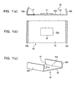
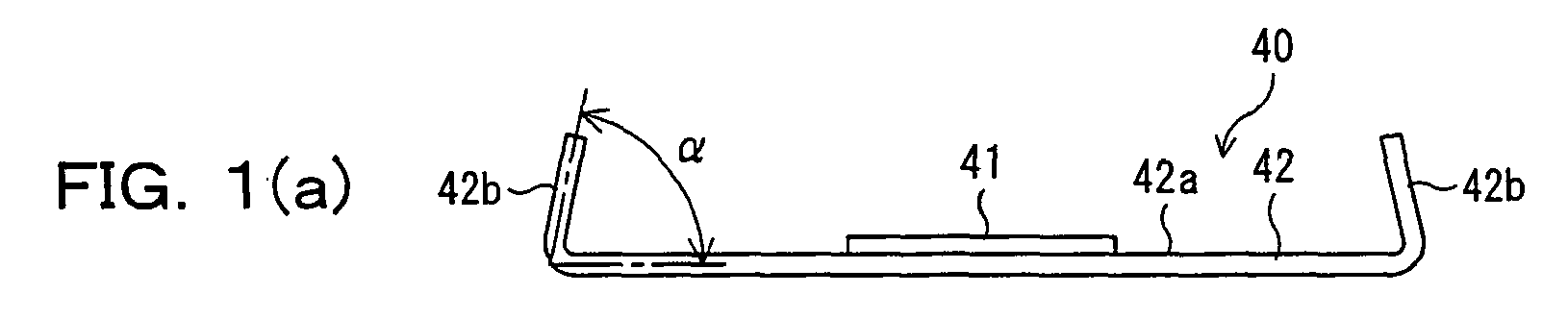
- the IC tag 40 includes an IC tag main body 41 and a plate 42 equipped with the IC tag main body 41.
- a sheet product in this embodiment is a corrugated board manufactured by a corrugator.
- the IC tag main body 41 is plate shaped base body made of a vinyl sheet, etc., and includes an IC chip and a radio antenna, which are embedded in the IC tag main body 41.
- the plate 42 has a flat portion 42a formed into a rectangular or strip shape with plastic resin, and onto one surface (upper surface as the plate 42 is placed on a product batch) of the flat portion 42a, the IC tag main body 41 is glued. Note that for gluing the IC tag main body 41 onto the flat portion 42a of the plate 42, adhesive tape such as double-coated tape etc. may be employed.
- the IC tag main body 41 may be embedded in the flat portion 42a of the plate 42. In such a case, the IC chip and radio antenna of the IC tag main body 41 may be embedded directly in the flat portion 42a of the plate 42.
- the plate portion of the IC tag main body 41 is constructed of the plate 42 itself.
- the flat portion 42a of the plate 42 has at its longitudinal ends (i.e. facing short side of a rectangular or strip shape) protrusions 42b, which extend in the direction where the IC tag main body 41 is installed.
- the protrusion 42b of this embodiment is formed by bending each end of the plate 42 to the one side of the flat portion 42a on which the IC tag main body 41 is glued. In this embodiment, the protrusion 42b is bent at an angle ⁇ slightly more acute than a right angle relative to the side of the flat portion 42a.
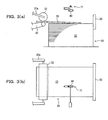
- the IC tag holding tool 71 is equipped with a base member 72 with a holding pawl 72a; a moving member 74 with a holding pawl 74a, movably supported in a predetermined direction through a guide member not shown on the base member 72; and an actuator (e.
- the predetermined direction means the direction in which the holding pawls 72a and 74a are moved toward or away from each other.
- the IC tag holing tool 71 is also movable by a mover (e.g., an air cylinder connected through a piston rod 75a) 75. Therefore, by movements of the holding pawls 72a, 74a and the IC tag holing tool 71, the IC tag 40 can be conveyed over and placed onto the product batch 22. More specifically, by moving the holding pawls 72a and 74a toward each other so that the distance therebetween is shorter than the inner sides of both protrusions 42b of the IC tag 40, then disposing them between the inner sides of both protrusions 42b, and moving the holding pawls 72a and 74a away from each other, as shown in FIGS.
- a mover e.g., an air cylinder connected through a piston rod 75a
- the IC tag 40 can be held. With the IC tag 40 held, by moving the IC tag holding tool 71, as shown in FIG. 3 , the IC tag 40 is moved over the product batch 22. Then, by moving the holding pawls 72a and 74a toward each other, they are separated from the inner sides of both protrusions 42b of the IC tag 40, and the IC tag 40 falls off the IC tag holding tool 71 and is placed onto the product batch 22.
- the product batch 22 can be managed as described later.
- the fall of the IC tag 40 onto the product batch 22 by the inward movement of the holding pawls 72a and 74a is performed over a stacker 30 from which the corrugated board 20 is discharged through a conveying unit (a conveyor 31 and a discharge roller 32 pivotally supported by support arms 32a) from the corrugator (not shown in FIGS. 3(a) and 3(b) ), for example, at the timing where the last corrugated board 20 constituting a batch abuts the back stop 33 of the stacker 30.
- a conveying unit a conveyor 31 and a discharge roller 32 pivotally supported by support arms 32a
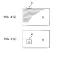
- the IC tag 40 is placed on the product batch 22.
- the stacker 30, as shown in FIG. 5 is provided near the downstream end of the corrugator 1.
- the product batch 22 formed by the stacker 30 is placed on the conveyor 34 and transferred to a product batch receiving position of an automatic guided vehicle (AGV) 35. Thereafter, by the AGV 35, one of the box blank making machines 2 to be processed is selected and the corresponding product batch 22 is fed to the selected box blank making machine.
- AGV automatic guided vehicle
- an AGV 35 Over the conveyor 34 which is upstream part of the product batch receiving position an AGV 35 (e.g., over the downstream end of the conveyor 34 in this embodiment), a reader 61 to read out information from the IC tag 40 is installed face down on a gate-shaped support frame 62 so that its direction of detection faces the IC tag 40 on the conveyor 11 [sic].
- the AGV 35 selects a box blank making machine to be processed according to the information of the product batch 22 read by the reader 61, and conveys the product batch 22 traveling on a sending-out root 35a to the selected box blank making machine.
- Each of the box blank making machines 2 is equipped with a sending-in conveyor 36.
- a reader 61 to read out information from the IC tag 40 is installed face down on a gate-shaped support frame 62 so that its direction of detection faces the IC tag 40 on the conveyor 11 [sic].
- Each of the box blank making machines 2 manufactures corrugated board container blanks in the processing contents according to the information of the product batch 22 read by the reader 61.
- the manufactured corrugated board container blanks are sent out from the sending-out conveyor 37 as a product batch, and shipped by transportation means such as a truck etc.
- the IC tag 40 on the product batch 22 is collected and put into a collecting box. If the IC tag is put into the collecting box, it can be confirmed with a detector within the collecting box whether a batch of sheets being conveyed has been manufactured according to the production plan. This confirmation makes it possible to perform the setting of the box blank making machine correctly.
- the plate 42 has at the longitudinal ends the protrusions 42b extending from the flat portion 42a, so if it is held through the protrusions 42b by the IC tag holding tool 71 or manually, the IC tag 40 can be easily and reliably picked up.
- the operations can be readily performed, and the use of the IC tag holding tool 71 can make automation of these operations easy.
- the sheet product collides with the protrusion 42b and the direct collision with the IC tag main body 41 installed on the flat portion 42a of the IC tag 40 is avoided, so that the joined portion between the plate 42 and the IC tag main body 41, and the IC tag main body 41 itself can be protected.
- the protrusions 42b in this embodiment are formed at the opposite longitudinal ends of the plate 42, so when picking up the IC tag 40, either or both of the protrusions [sic] can be used and therefore operability is enhanced.
- the joined portion between the plate 42 and the IC tag main body 41, and the IC tag main body 41 itself can be more reliably protected by both protrusions 42b.
- protrusions [sic] are formed by bending the opposite ends of the plate [sic], they are flat in shape and can be easily held by mechanical holding means or operator's hand.
- the present invention has been described with reference to the preferred embodiment thereof, the invention is not to be limited to the details given herein, but may be modified within the scope of the invention hereinafter claimed.
- the IC tag and the IC tag holding tool are used in the conveyance of a batch of corrugated boards as an example of sheet products
- the IC tag may be placed on a product batch of corrugated board container blanks manufactured and used to manage the shipment of them.
- the IC tag and the IC tag holding tool may be used to manage not only corrugated boards and corrugated board container blanks but also a product batch of other sheet products.
- the protrusions 42b are provided at the opposite longitudinal ends of the flat portion 42a, like IC tags 40B and 40C shown in FIGS. 7 (a) and 7 (b) , even if a single protrusion 42b is formed in one of the opposite longitudinal ends of a flat portion 42a, nearly the same advantages as the above embodiment can be obtained.
- the other end having no protrusion of the IC tag can be used inserted between sheet products of a product batch, so this case can be used for various purposes.
- the angle ⁇ of the protrusion 42b to the flat portion 42a is not limited to the acute angle of the above embodiment, but may be a right angle.
- the protrusion is formed at an obtuse angle, as shown in FIGS. 7(c) and 7(d) , IC tags 40C can be stacked.
- the protrusion is not to be limited to the shape obtained by bending the plate.
- the plate 42 is rectangular in shape at planer view, it is not to be limited to the rectangular shape.
Landscapes
- Engineering & Computer Science (AREA)
- Computer Hardware Design (AREA)
- Microelectronics & Electronic Packaging (AREA)
- Physics & Mathematics (AREA)
- General Physics & Mathematics (AREA)
- Theoretical Computer Science (AREA)
- Mechanical Engineering (AREA)
- Credit Cards Or The Like (AREA)
- Making Paper Articles (AREA)
- Surgical Instruments (AREA)
- Adhesives Or Adhesive Processes (AREA)
- Polishing Bodies And Polishing Tools (AREA)
Abstract

Description
- The present invention relates to integrated circuit (IC) tags suitable for use in placing on sheet products such as corrugated boards and corrugated board container blanks handled in batch units after production, and managing the sheet products.
- In the case of sheet products including paper products such as corrugated boards and corrugated board container blanks (corrugated board container material at the previous state of assembly)manufactured from the corrugated boards, a predetermined number of stacked sheets are conveyed or shipped in batch units.
For example,FIG. 8 schematically illustrates the flow in which corrugated board container blanks are manufactured from paper roll. As illustrated inFIG. 8 , in the case of manufacturing corrugated board container blanks, a number ofpaper rolls 10 to order are fed to acorrugator 1, in whichcorrugated boards 20 to order are manufactured using thesepaper rolls 10. Downstream of thecorrugator 1, there are provided usually several boxblank making machines 2, in which thecorrugated boards 20 are scored, cut, and glued to manufacture flat corrugatedboard container blanks 21 before being set up. The manufactured corrugatedboard container blanks 21 are stacked in predetermined batch units, loaded in transportation means such as a truck etc., and shipped. - In such a box blank manufacturing process, in conveying to the box blank making
machine 2 thecorrugated boards 20 manufactured with thecorrugator 1, or in shipping the corrugatedboard container blanks 21 manufactured with the box blank makingmachine 2, thecorrugated boards 20 or the corrugatedboard container blanks 21 are conveyed or shipped in units of a batch consisting of a predetermined number of stacked sheets. When conveying or shipping, it is necessary to specify and manage each batch of thecorrugated boards 20 or the corrugated board container blanks 21. - As a general method for managing such a batch of products, it is possible to put a unique number or symbol on each product batch and register in a computer the attribute (type etc.) of a product batch according to this number, but in this case, it is fairly difficult to display a unique number etc. on each product batch so that it is clearly visible from outside. Furthermore, this method has to rely on visual inspection.
- In contrast to this,
patent document 1 discloses a technique pertaining to an identification tag attached to a pallet for carrying loads with a forklift, hand lift or the like for pallet identification. Note that an ID tag employing an integrated circuit chip is referred to as an IC tag.
Patent Document 1: Japanese patent laid-open publication No.2003-95270 - As in
patent document 1, if an ID tag is installed on a pallet placing a product batch thereon, the product batch on the pallet can be specified, but since this case is based on the assumption that a pallet is used in conveying or shipping a product batch, the product batch cannot be applied if no pallet is employed.
Hence, for instance, a card orsheet IC tag 40 such as that shown inFIG. 9 , as shown inFIG. 10 , is placed on aproduct batch 22 conveyed on a product line (e.g., on aconveyor 11 in this example), and with areader 61 provided on the product line, information is read out from eachIC tag 40 using radio waves. This makes it possible to manage theproduct batch 22 automatically by just placing theIC tag 40 on theproduct batch 22. - Note that the
IC tag 40 consists of an IC tagmain body 41 embedding an IC chip and a radio antenna therein, and a card orsheet plate 42 made from resin or paper on which the IC tagmain body 41 is stuck. Thereader 61 is installed face down on a gate-shaped support frame 62 so that the direction of detection faces theIC tag 40 on theconveyor 11.
Thus, because theIC tag 40 is only placed on theproduct batch 22, for example, with agripping arm 70 with agripper 70a at its lower end such as the one shown inFIG. 11 , theIC tag 40 can be disposed on theproduct batch 22 automatically. - However, if the
IC tag 40 is formed into a simple flat shape, as shown inFIG. 11 , when placing theIC tag 40 onto theproduct batch 22 automatically, or when automatically collecting theIC tag 40 from theproduct batch 22, it is difficult to pick up theIC tag 40 one by one with thegripper 70a etc.
In addition, taking reading of theIC tag 40 by thereader 61 into consideration, theIC tag 40 is disposed on theproduct batch 22 so that the IC tagmain body 41 is exposed to the upper surface of theplate 42, so if theIC tag 40 is formed into a simple flat shape, the IC tagmain body 41 will be exposed to the top of theproduct batch 22, and for example, when a product such as a corrugated board or a corrugated board container blank drops down to theproduct batch 22, there is a possibility that the IC tagmain body 41 will be separated from theplate 42, or the IC tagmain body 41 itself will be damaged. - The present invention has been made in view of the circumstances described above. Accordingly, it is an object of the present invention to provide an IC tag which is capable of being reliably picked up one by one and of preventing frombeing damaged when placed on a product batch.
- To achieve the aforementioned object and in accordance with the present invention, there is provided an integrated circuit (IC) tag placed on sheet products handled in batch units after production, and used to manage the sheet products. The IC tag includes an IC tag main body having an IC chip and a radio antenna embedded therein, and a plate with a flat portion in which the IC tag main body is installed. The plate has at its one end a protrusion extending from the flat portion.
- Preferably, the IC tag main body is embedded in the plate or stuck on one surface of the plate. The sticking may be accomplished by an adhesive, or tape such as double-coated tape etc.
It is preferable that the protrusion be formed by bending the plate. - It is also preferable that the protrusion be formed in each of the opposite ends of the plate.
- According to the IC tag of the present invention, the plate of the IC tag has at its one ends the protrusions extending from the flat portion, so if the IC tag is held through the protrusions when placing it onto a batch of sheet products handled in batch units or when collecting it from the product batch, the IC tag can be easily picked up. In addition, even when a sheet product etc. drop down to the IC tag on a batch of sheet products, the sheet product collides with the protrusion, and the direct collision with the IC tag main body installed on the flat portion of the IC tag is avoided. Consequently, the joined portion between the plate and the IC tag main body, and the IC tag main body itself, are protected.
- If the IC tag main body is embedded in the plate, damage to the IC tag main body can be prevented. If the IC tag main body is stuck on one surface of the plate, the IC tag main body can be easily installed on an elastic plate.
If the protrusion is formed by bending the plate, it is flat in shape and can be easily held. Depending on the degree that the protrusion is bent, stacked IC tags can be easily picked up one by one. - If the protrusions are formed at the opposite ends of the plate, when picking up the IC tag, either or both of the protrusions can be used and therefore operability is enhanced. In addition, even if a sheet product drops down to the IC tag, the joined portion between the plate and the IC tag main body, and the IC tag main body itself can be protected by both protrusions.
-
-
FIG. 1 (a) is a side view showing an IC tag according to an embodiment of the present invention; -
FIG. 1(b) is a plan view of the IC tag shown inFIG. 1(a) ; -
FIG. 1 (c) is a perspective view of the IC tag shown inFIG. 1(a) ; -
FIG. 2 (a) is a front view showing an IC tag holding tool according to the embodiment of the present invention; -
FIG. 2 (b) is a plan view of the IC tag holding tool shown inFIG. 2(a) ; -
FIG. 3(a) is a front view used to explain the - installing position and operation of the IC tag holding tool according to the embodiment of the present invention;
-
FIG. 3(b) is a plan view used to explain the installing position and operation of the IC tag holding tool shown inFIG. 3(a) ; -
FIG. 4 (a) is a front view used to explain the state in which the IC tag is used according to the embodiment of the present invention; -
FIG. 4 (b) is a plan view used to explain the state in which the IC tag is used shown inFIG. 4(a) ; -
FIG. 5 is a schematic plan view of a box blank making factory equipped with a corrugator and a box blank making machine for explaining the state in which the IC tag according to the embodiment of the present invention is used; -
FIG. 6 is a side view of a product batch for explaining advantages of the IC tag according to the embodiment of the present invention; -
FIGS. 7(a) to 7(d) are side views showing modifications of the IC tag according to the embodiment of the present invention; -
FIG. 8 is a schematic diagram showing the flow of paper roll used in the manufacture of paper products with the manufacture of corrugated board container blanks as an example; -
FIG. 9 is a perspective view used to explain a conventional IC tag; -
FIG. 10 is a perspective view used to explain the situation in which the conventional IC tag is used; and -
FIG. 11 is a side view used to explain how the conventional IC tag is conveyed. -
- 40
- IC tag
- 41
- IC tag main body
- 42
- Plate
- 42a
- Flat portion of the
plate 42 - 42b
- Protrusion
- 71
- IC tag holding tool
- 72
- Base member
- 72a
- Holding pawl
- 73
- Actuator (e.g. , an air cylinder in this embodiment)
- 74
- Moving member
- 74a
- Holding pawl
- 75
- Mover (air cylinder)
- An embodiment of the present invention will be described hereinafter with reference to the drawings.
-
FIGS. 1 to 6 are used to explain an IC tag and an IC tag holding tool according to an embodiment of the present invention.
Referring initially to the IC tag according to this embodiment, as illustrated inFIGS. 1(a) to 1(c) , theIC tag 40 is placed on sheet products handled in batch units after production (hereinafter referred to as a product batch) and used to manage this product batch. TheIC tag 40 includes an IC tagmain body 41 and aplate 42 equipped with the IC tagmain body 41. Note that a sheet product in this embodiment is a corrugated board manufactured by a corrugator. - The IC tag
main body 41 is plate shaped base body made of a vinyl sheet, etc., and includes an IC chip and a radio antenna, which are embedded in the IC tagmain body 41.
Theplate 42 has aflat portion 42a formed into a rectangular or strip shape with plastic resin, and onto one surface (upper surface as theplate 42 is placed on a product batch) of theflat portion 42a, the IC tagmain body 41 is glued. Note that for gluing the IC tagmain body 41 onto theflat portion 42a of theplate 42, adhesive tape such as double-coated tape etc. may be employed. The IC tagmain body 41 may be embedded in theflat portion 42a of theplate 42. In such a case, the IC chip and radio antenna of the IC tagmain body 41 may be embedded directly in theflat portion 42a of theplate 42. In the construction, the plate portion of the IC tagmain body 41 is constructed of theplate 42 itself. - If the IC tag
main body 41 is embedded in theplate 42, damage to the IC tagmain body 41 can be prevented. In addition, if the IC tagmain body 41 is glued onto a surface facing in the direction of the paper tube center of theplate 42 as it is installed on the inner periphery of the paper tube, the IC tagmain body 41 can be easily installed on theplate 42.
Theflat portion 42a of theplate 42 has at its longitudinal ends (i.e. facing short side of a rectangular or strip shape)protrusions 42b, which extend in the direction where the IC tagmain body 41 is installed. Theprotrusion 42b of this embodiment is formed by bending each end of theplate 42 to the one side of theflat portion 42a on which the IC tagmain body 41 is glued. In this embodiment, theprotrusion 42b is bent at an angle α slightly more acute than a right angle relative to the side of theflat portion 42a. - The reason the angle α of the
protrusion 42b to theflat portion 42a is acute is that in holding theIC tag 40, as shown inFIGS. 3(a) and 3(b) , theIC tag 40 is held through the inner sides of theprotrusions 42b by the ICtag holding tool 71.
The IC tag holding tool according to the present embodiment is described below. As illustrated inFIGS. 2(a), 2(b) ,3(a), and 3(b) , the ICtag holding tool 71 is equipped with abase member 72 with a holdingpawl 72a; a movingmember 74 with a holdingpawl 74a, movably supported in a predetermined direction through a guide member not shown on thebase member 72; and an actuator (e. g. , an air cylinder in this embodiment) 73 interposed between thebase member 72 and the movingmember 74 to drive the movingmember 74 in the predetermined direction. Note that the predetermined direction means the direction in which the holdingpawls - The IC
tag holing tool 71 is also movable by a mover (e.g., an air cylinder connected through apiston rod 75a) 75. Therefore, by movements of the holdingpawls tag holing tool 71, theIC tag 40 can be conveyed over and placed onto theproduct batch 22.
More specifically, by moving the holdingpawls protrusions 42b of theIC tag 40, then disposing them between the inner sides of bothprotrusions 42b, and moving the holdingpawls FIGS. 2 (a) and 2(b) , theIC tag 40 can be held. With theIC tag 40 held, by moving the ICtag holding tool 71, as shown inFIG. 3 , theIC tag 40 is moved over theproduct batch 22. Then, by moving the holdingpawls protrusions 42b of theIC tag 40, and theIC tag 40 falls off the ICtag holding tool 71 and is placed onto theproduct batch 22. - Because the IC tag and the IC tag holding tool according to this embodiment are constructed as described above, with the
IC tag 40 placed on theproduct batch 22, theproduct batch 22 can be managed as described later. - That is, for example, as shown in
FIGS. 3(a) and 3(b) , the fall of theIC tag 40 onto theproduct batch 22 by the inward movement of the holdingpawls stacker 30 from which thecorrugated board 20 is discharged through a conveying unit (aconveyor 31 and adischarge roller 32 pivotally supported bysupport arms 32a) from the corrugator (not shown inFIGS. 3(a) and 3(b) ), for example, at the timing where the lastcorrugated board 20 constituting a batch abuts theback stop 33 of thestacker 30. - As a result of the fall of the
IC tag 40, as shown inFIGS. 4(a) and 4(b) , theIC tag 40 is placed on theproduct batch 22. Note that thestacker 30, as shown inFIG. 5 , is provided near the downstream end of thecorrugator 1. Theproduct batch 22 formed by thestacker 30 is placed on theconveyor 34 and transferred to a product batch receiving position of an automatic guided vehicle (AGV) 35. Thereafter, by theAGV 35, one of the boxblank making machines 2 to be processed is selected and thecorresponding product batch 22 is fed to the selected box blank making machine. - Over the
conveyor 34 which is upstream part of the product batch receiving position an AGV 35 (e.g., over the downstream end of theconveyor 34 in this embodiment), areader 61 to read out information from theIC tag 40 is installed face down on a gate-shapedsupport frame 62 so that its direction of detection faces theIC tag 40 on the conveyor 11 [sic]. TheAGV 35 selects a box blank making machine to be processed according to the information of theproduct batch 22 read by thereader 61, and conveys theproduct batch 22 traveling on a sending-out root 35a to the selected box blank making machine. - Each of the box
blank making machines 2 is equipped with a sending-inconveyor 36. In the sending-inconveyor 36, areader 61 to read out information from theIC tag 40 is installed face down on a gate-shapedsupport frame 62 so that its direction of detection faces theIC tag 40 on the conveyor 11 [sic]. Each of the boxblank making machines 2 manufactures corrugated board container blanks in the processing contents according to the information of theproduct batch 22 read by thereader 61. The manufactured corrugated board container blanks are sent out from the sending-outconveyor 37 as a product batch, and shipped by transportation means such as a truck etc. - At the upstream end of each box
blank making machine 2, for example, by an operator, theIC tag 40 on theproduct batch 22 is collected and put into a collecting box. If the IC tag is put into the collecting box, it can be confirmed with a detector within the collecting box whether a batch of sheets being conveyed has been manufactured according to the production plan. This confirmation makes it possible to perform the setting of the box blank making machine correctly.
Thus, according to the IC tag [sic] of the present invention, theplate 42 has at the longitudinal ends theprotrusions 42b extending from theflat portion 42a, so if it is held through theprotrusions 42b by the ICtag holding tool 71 or manually, theIC tag 40 can be easily and reliably picked up. - Therefore, when placing the
IC tag 40 onto theproduct batch 22, and when collecting theIC tag 40 placed on theproduct batch 22, the operations can be readily performed, and the use of the ICtag holding tool 71 can make automation of these operations easy.
In addition, as shown inFIG. 6 , even when a sheet product such as a corrugated board etc. drops down to the IC tag on theproduct batch 22, the sheet product collides with theprotrusion 42b and the direct collision with the IC tagmain body 41 installed on theflat portion 42a of theIC tag 40 is avoided, so that the joined portion between theplate 42 and the IC tagmain body 41, and the IC tagmain body 41 itself can be protected. - Particularly, the
protrusions 42b in this embodiment are formed at the opposite longitudinal ends of theplate 42, so when picking up theIC tag 40, either or both of the protrusions [sic] can be used and therefore operability is enhanced. In addition, even if a sheet product drops down to the IC tag, the joined portion between theplate 42 and the IC tagmain body 41, and the IC tagmain body 41 itself can be more reliably protected by bothprotrusions 42b. - Because the protrusions [sic] are formed by bending the opposite ends of the plate [sic], they are flat in shape and can be easily held by mechanical holding means or operator's hand.
- While the present invention has been described with reference to the preferred embodiment thereof, the invention is not to be limited to the details given herein, but may be modified within the scope of the invention hereinafter claimed.
For example, although it has been described that the IC tag and the IC tag holding tool according to this embodiment are used in the conveyance of a batch of corrugated boards as an example of sheet products, the IC tag may be placed on a product batch of corrugated board container blanks manufactured and used to manage the shipment of them. The IC tag and the IC tag holding tool may be used to manage not only corrugated boards and corrugated board container blanks but also a product batch of other sheet products. - In the above embodiment, although the
protrusions 42b are provided at the opposite longitudinal ends of theflat portion 42a, like IC tags 40B and 40C shown inFIGS. 7 (a) and 7 (b) , even if asingle protrusion 42b is formed in one of the opposite longitudinal ends of aflat portion 42a, nearly the same advantages as the above embodiment can be obtained. In addition, for instance, the other end having no protrusion of the IC tag can be used inserted between sheet products of a product batch, so this case can be used for various purposes. - In the case where the protrusion is formed by bending the plate, the angle α of the
protrusion 42b to theflat portion 42a is not limited to the acute angle of the above embodiment, but may be a right angle. In addition, if the protrusion is formed at an obtuse angle, as shown inFIGS. 7(c) and 7(d) ,IC tags 40C can be stacked.
Of course, the protrusion is not to be limited to the shape obtained by bending the plate. - Finally, in the above embodiment, although the
plate 42 is rectangular in shape at planer view, it is not to be limited to the rectangular shape.
Claims (5)
- An integrated circuit (IC) tag placed on sheet products handled in batch units after production, and used to manage said sheet products, comprising:an IC tag main body having an IC chip and a radio antenna embedded therein; anda plate with a flat portion in which said IC tag main body is installed;wherein said plate has at its one end a protrusion extending from said flat portion.
- The IC tag as set forth in claim 1, wherein said IC tag main body is embedded in said plate.
- The IC tag as set forth in claim 1, wherein said IC tag main body is stuck on one surface of said plate.
- The IC tag as set forth in any one of claims 1 to 3, wherein said protrusion is formed by bending said plate.
- The IC tag as set forth in any one of claims 1 to 4, wherein saidprotrusion is formed in each of opposite ends of said plate.
Applications Claiming Priority (2)
| Application Number | Priority Date | Filing Date | Title |
|---|---|---|---|
| JP2007021946A JP2008186423A (en) | 2007-01-31 | 2007-01-31 | Ic tag |
| PCT/JP2008/051545 WO2008093790A1 (en) | 2007-01-31 | 2008-01-31 | Ic tag |
Publications (3)
| Publication Number | Publication Date |
|---|---|
| EP2120186A1 true EP2120186A1 (en) | 2009-11-18 |
| EP2120186A4 EP2120186A4 (en) | 2010-02-24 |
| EP2120186B1 EP2120186B1 (en) | 2011-05-18 |
Family
ID=39674095
Family Applications (1)
| Application Number | Title | Priority Date | Filing Date |
|---|---|---|---|
| EP08704292A Not-in-force EP2120186B1 (en) | 2007-01-31 | 2008-01-31 | Ic tag |
Country Status (7)
| Country | Link |
|---|---|
| US (1) | US20100012734A1 (en) |
| EP (1) | EP2120186B1 (en) |
| JP (1) | JP2008186423A (en) |
| KR (1) | KR20090110921A (en) |
| AT (1) | ATE510269T1 (en) |
| TW (1) | TW200846255A (en) |
| WO (1) | WO2008093790A1 (en) |
Family Cites Families (8)
| Publication number | Priority date | Publication date | Assignee | Title |
|---|---|---|---|---|
| JP3924962B2 (en) * | 1998-10-30 | 2007-06-06 | 株式会社デンソー | ID tag for dishes |
| DE50114499D1 (en) * | 2001-03-28 | 2009-01-02 | Latschbacher Gmbh | Marking element for marking wood, in particular tree trunks |
| JP4797281B2 (en) * | 2001-06-01 | 2011-10-19 | 大日本印刷株式会社 | IC tag inlet insert-in-mold molding method |
| JP4068832B2 (en) | 2001-07-17 | 2008-03-26 | 日本パレットレンタル株式会社 | Pallet with identification tag |
| JP3803085B2 (en) * | 2002-08-08 | 2006-08-02 | 株式会社日立製作所 | Wireless IC tag |
| JP4290620B2 (en) * | 2004-08-31 | 2009-07-08 | 富士通株式会社 | RFID tag, RFID tag antenna, RFID tag antenna sheet, and RFID tag manufacturing method |
| JP5008289B2 (en) * | 2004-09-24 | 2012-08-22 | 株式会社半導体エネルギー研究所 | Manufacturing method and peeling method of semiconductor device |
| JP2007122482A (en) * | 2005-10-28 | 2007-05-17 | Fujitsu Ltd | RFID tag and RFID tag manufacturing method |
-
2007
- 2007-01-31 JP JP2007021946A patent/JP2008186423A/en not_active Withdrawn
-
2008
- 2008-01-31 US US12/523,749 patent/US20100012734A1/en not_active Abandoned
- 2008-01-31 AT AT08704292T patent/ATE510269T1/en not_active IP Right Cessation
- 2008-01-31 KR KR1020097017849A patent/KR20090110921A/en not_active Ceased
- 2008-01-31 WO PCT/JP2008/051545 patent/WO2008093790A1/en not_active Ceased
- 2008-01-31 TW TW097103811A patent/TW200846255A/en unknown
- 2008-01-31 EP EP08704292A patent/EP2120186B1/en not_active Not-in-force
Also Published As
| Publication number | Publication date |
|---|---|
| TW200846255A (en) | 2008-12-01 |
| JP2008186423A (en) | 2008-08-14 |
| ATE510269T1 (en) | 2011-06-15 |
| US20100012734A1 (en) | 2010-01-21 |
| EP2120186A4 (en) | 2010-02-24 |
| WO2008093790A1 (en) | 2008-08-07 |
| EP2120186B1 (en) | 2011-05-18 |
| KR20090110921A (en) | 2009-10-23 |
Similar Documents
| Publication | Publication Date | Title |
|---|---|---|
| KR101424682B1 (en) | Picking system and picking method | |
| EP1632926B1 (en) | A label comprising a transponder and a system comprising a transponder | |
| JP2001240046A (en) | Container and manufacturing method thereof | |
| CN100454195C (en) | Automatic Manufacturing Control System | |
| JP5353326B2 (en) | ID label affixing device | |
| CN1646374A (en) | Methods of applying radio-frequency identification tags | |
| EP1604914A2 (en) | Dunnage article | |
| JP2002308437A (en) | Inspection system using RFID tag | |
| EP3091481B1 (en) | Marking device and marking method | |
| JP2008155643A (en) | Product flow control device in printing factory | |
| JP7264702B2 (en) | Variable dimension box blank manufacturing device, variable dimension box blank manufacturing method, box blank assembly method, and variable dimension automatic packaging line | |
| EP4035883A1 (en) | Cardboard box production device, box production method, and box processing method | |
| EP2120186B1 (en) | Ic tag | |
| US20100038430A1 (en) | Large-unitized inlet manufacturing method, inlet adhesive tape, its manufacturing method, and its manufacturing device | |
| US12024327B2 (en) | System and method for assisting error recovery in an automated packaging process and system and method for automatically packaging shipment sets | |
| CN111989694A (en) | Electronic tag writing system and method thereof | |
| JP4828384B2 (en) | Automatic sticker sticking system for gaming machines | |
| JP4470662B2 (en) | How to handle goods | |
| JP2000168976A (en) | Sheet transfer device | |
| JP5040450B2 (en) | RFID tag communication system for baggage | |
| JP2006040023A (en) | RFID printer and control method | |
| TW202128410A (en) | Cardboard box-making apparatus, box-making method, and box-making processing method | |
| US20120312230A1 (en) | Apparatus for fabricating rfid label tag | |
| CN114408299B (en) | PCB sorting and packaging method and device, electronic equipment and storage medium | |
| JP4136306B2 (en) | Article delivery system, slip for article delivery system and automatic slip pasting device |
Legal Events
| Date | Code | Title | Description |
|---|---|---|---|
| PUAI | Public reference made under article 153(3) epc to a published international application that has entered the european phase |
Free format text: ORIGINAL CODE: 0009012 |
|
| 17P | Request for examination filed |
Effective date: 20090717 |
|
| AK | Designated contracting states |
Kind code of ref document: A1 Designated state(s): AT BE BG CH CY CZ DE DK EE ES FI FR GB GR HR HU IE IS IT LI LT LU LV MC MT NL NO PL PT RO SE SI SK TR |
|
| A4 | Supplementary search report drawn up and despatched |
Effective date: 20100122 |
|
| RIC1 | Information provided on ipc code assigned before grant |
Ipc: G06K 19/04 20060101AFI20080819BHEP Ipc: B31B 1/06 20060101ALI20100118BHEP Ipc: B31B 1/98 20060101ALI20100118BHEP Ipc: G06K 19/077 20060101ALI20100118BHEP |
|
| DAX | Request for extension of the european patent (deleted) | ||
| RAP1 | Party data changed (applicant data changed or rights of an application transferred) |
Owner name: MITSUBISHI HEAVY INDUSTRIES PRINTING & PACKING MAC |
|
| RAP1 | Party data changed (applicant data changed or rights of an application transferred) |
Owner name: MITSUBISHI HEAVY INDUSTRIES PRINTING & PACKAGING M |
|
| GRAP | Despatch of communication of intention to grant a patent |
Free format text: ORIGINAL CODE: EPIDOSNIGR1 |
|
| GRAS | Grant fee paid |
Free format text: ORIGINAL CODE: EPIDOSNIGR3 |
|
| GRAA | (expected) grant |
Free format text: ORIGINAL CODE: 0009210 |
|
| REG | Reference to a national code |
Ref country code: GB Ref legal event code: FG4D |
|
| REG | Reference to a national code |
Ref country code: CH Ref legal event code: EP |
|
| REG | Reference to a national code |
Ref country code: IE Ref legal event code: FG4D |
|
| REG | Reference to a national code |
Ref country code: DE Ref legal event code: R096 Ref document number: 602008007007 Country of ref document: DE Effective date: 20110630 |
|
| REG | Reference to a national code |
Ref country code: NL Ref legal event code: VDEP Effective date: 20110518 |
|
| PG25 | Lapsed in a contracting state [announced via postgrant information from national office to epo] |
Ref country code: SE Free format text: LAPSE BECAUSE OF FAILURE TO SUBMIT A TRANSLATION OF THE DESCRIPTION OR TO PAY THE FEE WITHIN THE PRESCRIBED TIME-LIMIT Effective date: 20110518 Ref country code: PT Free format text: LAPSE BECAUSE OF FAILURE TO SUBMIT A TRANSLATION OF THE DESCRIPTION OR TO PAY THE FEE WITHIN THE PRESCRIBED TIME-LIMIT Effective date: 20110919 Ref country code: HR Free format text: LAPSE BECAUSE OF FAILURE TO SUBMIT A TRANSLATION OF THE DESCRIPTION OR TO PAY THE FEE WITHIN THE PRESCRIBED TIME-LIMIT Effective date: 20110518 Ref country code: LT Free format text: LAPSE BECAUSE OF FAILURE TO SUBMIT A TRANSLATION OF THE DESCRIPTION OR TO PAY THE FEE WITHIN THE PRESCRIBED TIME-LIMIT Effective date: 20110518 Ref country code: NO Free format text: LAPSE BECAUSE OF FAILURE TO SUBMIT A TRANSLATION OF THE DESCRIPTION OR TO PAY THE FEE WITHIN THE PRESCRIBED TIME-LIMIT Effective date: 20110818 |
|
| PG25 | Lapsed in a contracting state [announced via postgrant information from national office to epo] |
Ref country code: IS Free format text: LAPSE BECAUSE OF FAILURE TO SUBMIT A TRANSLATION OF THE DESCRIPTION OR TO PAY THE FEE WITHIN THE PRESCRIBED TIME-LIMIT Effective date: 20110918 Ref country code: FI Free format text: LAPSE BECAUSE OF FAILURE TO SUBMIT A TRANSLATION OF THE DESCRIPTION OR TO PAY THE FEE WITHIN THE PRESCRIBED TIME-LIMIT Effective date: 20110518 Ref country code: AT Free format text: LAPSE BECAUSE OF FAILURE TO SUBMIT A TRANSLATION OF THE DESCRIPTION OR TO PAY THE FEE WITHIN THE PRESCRIBED TIME-LIMIT Effective date: 20110518 Ref country code: LV Free format text: LAPSE BECAUSE OF FAILURE TO SUBMIT A TRANSLATION OF THE DESCRIPTION OR TO PAY THE FEE WITHIN THE PRESCRIBED TIME-LIMIT Effective date: 20110518 Ref country code: ES Free format text: LAPSE BECAUSE OF FAILURE TO SUBMIT A TRANSLATION OF THE DESCRIPTION OR TO PAY THE FEE WITHIN THE PRESCRIBED TIME-LIMIT Effective date: 20110829 Ref country code: CY Free format text: LAPSE BECAUSE OF FAILURE TO SUBMIT A TRANSLATION OF THE DESCRIPTION OR TO PAY THE FEE WITHIN THE PRESCRIBED TIME-LIMIT Effective date: 20110518 Ref country code: SI Free format text: LAPSE BECAUSE OF FAILURE TO SUBMIT A TRANSLATION OF THE DESCRIPTION OR TO PAY THE FEE WITHIN THE PRESCRIBED TIME-LIMIT Effective date: 20110518 Ref country code: GR Free format text: LAPSE BECAUSE OF FAILURE TO SUBMIT A TRANSLATION OF THE DESCRIPTION OR TO PAY THE FEE WITHIN THE PRESCRIBED TIME-LIMIT Effective date: 20110819 Ref country code: BE Free format text: LAPSE BECAUSE OF FAILURE TO SUBMIT A TRANSLATION OF THE DESCRIPTION OR TO PAY THE FEE WITHIN THE PRESCRIBED TIME-LIMIT Effective date: 20110518 |
|
| PG25 | Lapsed in a contracting state [announced via postgrant information from national office to epo] |
Ref country code: NL Free format text: LAPSE BECAUSE OF FAILURE TO SUBMIT A TRANSLATION OF THE DESCRIPTION OR TO PAY THE FEE WITHIN THE PRESCRIBED TIME-LIMIT Effective date: 20110518 |
|
| PG25 | Lapsed in a contracting state [announced via postgrant information from national office to epo] |
Ref country code: EE Free format text: LAPSE BECAUSE OF FAILURE TO SUBMIT A TRANSLATION OF THE DESCRIPTION OR TO PAY THE FEE WITHIN THE PRESCRIBED TIME-LIMIT Effective date: 20110518 Ref country code: CZ Free format text: LAPSE BECAUSE OF FAILURE TO SUBMIT A TRANSLATION OF THE DESCRIPTION OR TO PAY THE FEE WITHIN THE PRESCRIBED TIME-LIMIT Effective date: 20110518 |
|
| PG25 | Lapsed in a contracting state [announced via postgrant information from national office to epo] |
Ref country code: DK Free format text: LAPSE BECAUSE OF FAILURE TO SUBMIT A TRANSLATION OF THE DESCRIPTION OR TO PAY THE FEE WITHIN THE PRESCRIBED TIME-LIMIT Effective date: 20110518 Ref country code: PL Free format text: LAPSE BECAUSE OF FAILURE TO SUBMIT A TRANSLATION OF THE DESCRIPTION OR TO PAY THE FEE WITHIN THE PRESCRIBED TIME-LIMIT Effective date: 20110518 Ref country code: RO Free format text: LAPSE BECAUSE OF FAILURE TO SUBMIT A TRANSLATION OF THE DESCRIPTION OR TO PAY THE FEE WITHIN THE PRESCRIBED TIME-LIMIT Effective date: 20110518 Ref country code: SK Free format text: LAPSE BECAUSE OF FAILURE TO SUBMIT A TRANSLATION OF THE DESCRIPTION OR TO PAY THE FEE WITHIN THE PRESCRIBED TIME-LIMIT Effective date: 20110518 |
|
| PLBE | No opposition filed within time limit |
Free format text: ORIGINAL CODE: 0009261 |
|
| STAA | Information on the status of an ep patent application or granted ep patent |
Free format text: STATUS: NO OPPOSITION FILED WITHIN TIME LIMIT |
|
| 26N | No opposition filed |
Effective date: 20120221 |
|
| REG | Reference to a national code |
Ref country code: DE Ref legal event code: R097 Ref document number: 602008007007 Country of ref document: DE Effective date: 20120221 |
|
| PG25 | Lapsed in a contracting state [announced via postgrant information from national office to epo] |
Ref country code: MC Free format text: LAPSE BECAUSE OF NON-PAYMENT OF DUE FEES Effective date: 20120131 |
|
| REG | Reference to a national code |
Ref country code: CH Ref legal event code: PL |
|
| GBPC | Gb: european patent ceased through non-payment of renewal fee |
Effective date: 20120131 |
|
| REG | Reference to a national code |
Ref country code: FR Ref legal event code: ST Effective date: 20120928 |
|
| REG | Reference to a national code |
Ref country code: IE Ref legal event code: MM4A |
|
| PG25 | Lapsed in a contracting state [announced via postgrant information from national office to epo] |
Ref country code: LI Free format text: LAPSE BECAUSE OF NON-PAYMENT OF DUE FEES Effective date: 20120131 Ref country code: GB Free format text: LAPSE BECAUSE OF NON-PAYMENT OF DUE FEES Effective date: 20120131 Ref country code: CH Free format text: LAPSE BECAUSE OF NON-PAYMENT OF DUE FEES Effective date: 20120131 |
|
| PG25 | Lapsed in a contracting state [announced via postgrant information from national office to epo] |
Ref country code: FR Free format text: LAPSE BECAUSE OF NON-PAYMENT OF DUE FEES Effective date: 20120131 |
|
| PG25 | Lapsed in a contracting state [announced via postgrant information from national office to epo] |
Ref country code: IE Free format text: LAPSE BECAUSE OF NON-PAYMENT OF DUE FEES Effective date: 20120131 |
|
| PG25 | Lapsed in a contracting state [announced via postgrant information from national office to epo] |
Ref country code: BG Free format text: LAPSE BECAUSE OF FAILURE TO SUBMIT A TRANSLATION OF THE DESCRIPTION OR TO PAY THE FEE WITHIN THE PRESCRIBED TIME-LIMIT Effective date: 20110818 |
|
| PG25 | Lapsed in a contracting state [announced via postgrant information from national office to epo] |
Ref country code: MT Free format text: LAPSE BECAUSE OF FAILURE TO SUBMIT A TRANSLATION OF THE DESCRIPTION OR TO PAY THE FEE WITHIN THE PRESCRIBED TIME-LIMIT Effective date: 20110518 |
|
| PG25 | Lapsed in a contracting state [announced via postgrant information from national office to epo] |
Ref country code: TR Free format text: LAPSE BECAUSE OF FAILURE TO SUBMIT A TRANSLATION OF THE DESCRIPTION OR TO PAY THE FEE WITHIN THE PRESCRIBED TIME-LIMIT Effective date: 20110518 |
|
| PGFP | Annual fee paid to national office [announced via postgrant information from national office to epo] |
Ref country code: DE Payment date: 20140129 Year of fee payment: 7 |
|
| PG25 | Lapsed in a contracting state [announced via postgrant information from national office to epo] |
Ref country code: LU Free format text: LAPSE BECAUSE OF NON-PAYMENT OF DUE FEES Effective date: 20120131 |
|
| PGFP | Annual fee paid to national office [announced via postgrant information from national office to epo] |
Ref country code: IT Payment date: 20140116 Year of fee payment: 7 |
|
| PG25 | Lapsed in a contracting state [announced via postgrant information from national office to epo] |
Ref country code: HU Free format text: LAPSE BECAUSE OF FAILURE TO SUBMIT A TRANSLATION OF THE DESCRIPTION OR TO PAY THE FEE WITHIN THE PRESCRIBED TIME-LIMIT Effective date: 20080131 |
|
| REG | Reference to a national code |
Ref country code: DE Ref legal event code: R119 Ref document number: 602008007007 Country of ref document: DE |
|
| PG25 | Lapsed in a contracting state [announced via postgrant information from national office to epo] |
Ref country code: DE Free format text: LAPSE BECAUSE OF NON-PAYMENT OF DUE FEES Effective date: 20150801 |
|
| PG25 | Lapsed in a contracting state [announced via postgrant information from national office to epo] |
Ref country code: IT Free format text: LAPSE BECAUSE OF NON-PAYMENT OF DUE FEES Effective date: 20150131 |