EP2120013A2 - Inertial sensor misalignment and compensation - Google Patents
Inertial sensor misalignment and compensation Download PDFInfo
- Publication number
- EP2120013A2 EP2120013A2 EP09159357A EP09159357A EP2120013A2 EP 2120013 A2 EP2120013 A2 EP 2120013A2 EP 09159357 A EP09159357 A EP 09159357A EP 09159357 A EP09159357 A EP 09159357A EP 2120013 A2 EP2120013 A2 EP 2120013A2
- Authority
- EP
- European Patent Office
- Prior art keywords
- sensor element
- sensor
- chassis
- inertial
- respect
- Prior art date
- Legal status (The legal status is an assumption and is not a legal conclusion. Google has not performed a legal analysis and makes no representation as to the accuracy of the status listed.)
- Withdrawn
Links
Images

Classifications
-
- G—PHYSICS
- G01—MEASURING; TESTING
- G01C—MEASURING DISTANCES, LEVELS OR BEARINGS; SURVEYING; NAVIGATION; GYROSCOPIC INSTRUMENTS; PHOTOGRAMMETRY OR VIDEOGRAMMETRY
- G01C21/00—Navigation; Navigational instruments not provided for in groups G01C1/00 - G01C19/00
- G01C21/10—Navigation; Navigational instruments not provided for in groups G01C1/00 - G01C19/00 by using measurements of speed or acceleration
- G01C21/12—Navigation; Navigational instruments not provided for in groups G01C1/00 - G01C19/00 by using measurements of speed or acceleration executed aboard the object being navigated; Dead reckoning
- G01C21/16—Navigation; Navigational instruments not provided for in groups G01C1/00 - G01C19/00 by using measurements of speed or acceleration executed aboard the object being navigated; Dead reckoning by integrating acceleration or speed, i.e. inertial navigation
- G01C21/183—Compensation of inertial measurements, e.g. for temperature effects
-
- G—PHYSICS
- G01—MEASURING; TESTING
- G01B—MEASURING LENGTH, THICKNESS OR SIMILAR LINEAR DIMENSIONS; MEASURING ANGLES; MEASURING AREAS; MEASURING IRREGULARITIES OF SURFACES OR CONTOURS
- G01B11/00—Measuring arrangements characterised by the use of optical techniques
- G01B11/26—Measuring arrangements characterised by the use of optical techniques for measuring angles or tapers; for testing the alignment of axes
- G01B11/27—Measuring arrangements characterised by the use of optical techniques for measuring angles or tapers; for testing the alignment of axes for testing the alignment of axes
- G01B11/272—Measuring arrangements characterised by the use of optical techniques for measuring angles or tapers; for testing the alignment of axes for testing the alignment of axes using photoelectric detection means
Definitions
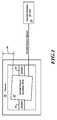
- an inertial-sensor assembly (ISA) 10 may be mounted within an enclosure or chassis 20 and vibration isolated from the chassis through the use of, for example, elastomeric isolators 30 operable to reduce sensor vibration exposure.
- a mechanical isolation may itself be a source of misalignment error.
- a typical navigation system does not, with great accuracy, take into account mechanical misalignment between the system chassis and the mechanically isolated ISA.
- an apparatus for providing information pertaining to the orientation of a vehicle to which the apparatus is coupled includes a chassis having a first interior surface and an inertial-sensor assembly disposed within the chassis and having a first exterior surface.
- a first sensor element is mounted on the first interior surface
- a second sensor element is mounted on the first exterior surface. At least one of the first and second sensor elements is configured to generate a first signal corresponding to an angle of displacement of the second sensor element with respect to the first sensor element.
- FIG. 1 is a schematic view of a prior-art apparatus
- FIG. 2 is a schematic view of an apparatus according to an embodiment of the present invention.
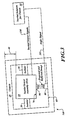
- FIG. 3 is a schematic view of an apparatus according to an alternative embodiment of the present invention.
- An embodiment of the invention enables a method of non-contact measure of the angular relationship between a navigation system chassis and an ISA. These measures of angle can then be incorporated into the inertial-reference computation to correct for mechanical misalignment within the system.
- FIG. 2 illustrated is an apparatus according to a first embodiment of the present invention.
- a chassis 20 having a first interior surface 60 and an ISA 10 disposed within the chassis and having a first exterior surface 70.
- a first sensor element 80 is mounted on the first interior surface 60
- a second sensor element 90 is mounted on the first exterior surface 70.
- the first sensor 80 includes a light source 100, such as a laser, and a photo-detector array 110.
- the second sensor 90 includes a reflective device, such as a mirror, operable to reflect emissions of the light source 100 on to the array 110.
- the array 110 is configured to generate at least one signal corresponding to an angle of displacement of the second sensor element 90 with respect to the first sensor element 80. These signals can be transmitted from the array 110 to a signal-conversion element 120, which may include a processor or other computational device, via a conductive element, such as a cable 105. Alternatively, such signals could be communicated to the conversion element 120 via known wireless techniques.
- the conversion element 120 may function to determine, based on the portion of the photoarray 110 on which light reflected by the second sensor element falls, the angle of the ISA 10 with respect to the chassis 20.
- the conversion element 120 may employ a look-up table, for example. Alternatively, all functionality of the conversion element 120 may be implemented in a processing device 50 discussed in further detail below.
- the placements of the light source 100, reflective device, and photodetector array 110 are selected so as to provide nominal light paths as close as possible to being perpendicular to the reflecting surface. This design feature may be implemented to minimize the impact of ISA translational motion on the position of the light-spot arrival at the detector array.
- An embodiment may employ two or more of such source/mirror/photoarray combinations ("sensor combination”), each such sensor combination being similar in configuration and functionality to the first and second sensor elements 80, 90 illustrated in FIG. 2 .
- each such sensor combination can be oriented in two or three different mutually orthogonal axes.
- each sensor combination (not shown) additional to the first and second sensor elements 80, 90 illustrated in FIG. 2 could include source/mirror/photoarray elements mounted on interior surfaces of the chassis 20 and exterior surfaces of the ISA 10 at respective 90-degree angles with respect to surfaces 60 and 70.
- Each sensor combination may be calibrated such that a reflected emission of the light source will fall on a portion of the photoarray corresponding to the chassis 20 being at rest.
- Angular displacement of the ISA 10 with respect to the chassis 20 will cause the reflected emission to fall on other portions of the photoarray directly corresponding to a particular magnitude of angular displacement. Measurement of up to three such angles indicated by up to three such sensor combinations would enable the processing device 50 to calculate the three-dimensional spatial orientation of the ISA 10 with respect to the chassis 20. In turn, this spatial-orientation determination can then, along with inertial-sensor signals 150 received from the ISA 10, be incorporated into the inertial-reference computation to account for misalignment of the ISA with respect to the chassis 20.
- the raw data from the array 110 could also be an added parameter in the solution. In such case, the raw data would be treated the same as other signals, such as temperature, used for compensation in the computation.
- FIG. 3 illustrated is an apparatus according to a second embodiment of the present invention.
- a chassis 20 having a first interior surface 60 and an ISA 10 disposed within the chassis and having a first exterior surface 70.
- a first sensor element 80 is mounted on the first interior surface 60
- a second sensor element 90 is mounted on the first exterior surface 70.
- the first sensor 80 includes an autocollimator.
- the second sensor 90 includes a reflective device, such as a mirror, operable to reflect images emitted by the first sensor 80.
- the first sensor 80 is configured to generate at least one signal corresponding to an angle of displacement of the second sensor element 90 with respect to the first sensor element 80. These signals can be transmitted from the first sensor 80 to a processing device 50 via a conductive element, such as a cable 105. Alternatively, such signals could be communicated to the processing device 50 via known wireless techniques.
- the first sensor 80 may function to determine, based on its reflected emissions, the angle of the ISA 10 with respect to the chassis 20.
- An embodiment may employ two or more of such autocollimator /mirror combinations ("sensor combination”), each such sensor combination being similar in configuration and functionality to the first and second sensor elements 80, 90 illustrated in FIG. 3 .
- each such sensor combination can be oriented in two or three different mutually orthogonal axes.
- each sensor combination (not shown) additional to the first and second sensor elements 80, 90 illustrated in FIG. 3 could include autocollimator /mirror elements mounted on interior surfaces of the chassis 20 and exterior surfaces of the ISA 10 at respective 90-degree angles with respect to surfaces 60 and 70.
- Each sensor combination may be calibrated such that a reflected image generated by the autocollimator will have an alignment corresponding to the chassis 20 being at rest.
- Angular displacement of the ISA 10 with respect to the chassis 20 will cause the reflected image to have alignments directly corresponding to a particular magnitude of angular displacement. Measurement of up to three such angles indicated by up to three such sensor combinations would enable the processing device 50 to calculate the three-dimensional spatial orientation of the ISA 10 with respect to the chassis 20. In turn, this spatial-orientation determination can then, along with inertial-sensor signals 150 received from the ISA 10, be incorporated into the inertial-reference computation to account for misalignment of the ISA with respect to the chassis 20.
Landscapes
- Engineering & Computer Science (AREA)
- Radar, Positioning & Navigation (AREA)
- Remote Sensing (AREA)
- Physics & Mathematics (AREA)
- General Physics & Mathematics (AREA)
- Automation & Control Theory (AREA)
- Length Measuring Devices By Optical Means (AREA)
- Length Measuring Devices With Unspecified Measuring Means (AREA)
- Gyroscopes (AREA)
Abstract
Description
- Certain inertial reference systems, such as those associated with aircraft navigation, for example, require the inertial sensors (e.g., gyroscopes, accelerometers, etc.) to be mechanically isolated from the rest of the system in order to attain the required inertial sensor accuracy and reliability. Referring to
FIG. 1 , for example, an inertial-sensor assembly (ISA) 10 may be mounted within an enclosure orchassis 20 and vibration isolated from the chassis through the use of, for example,elastomeric isolators 30 operable to reduce sensor vibration exposure. - However, such an isolation scheme allows the
ISA 10 to rotate through anangle 40 relative to thechassis 20 and, as such, the vehicle for which accurate spatial-orientation information is required. This may be due to a number of factors such as temperature, linear and angular acceleration, age, etc. Although, for purposes of clarity, rotation of theISA 10 in a one-dimensional plane is shown in the drawing figures, the ISA is free to rotate slightly in all three dimensions. In conventional strapdown inertial navigation system arrangements, this rotational motion of theISA 10 is generally unmeasured or otherwise unaccounted for in the inertial navigation solution calculated by aprocessing device 50 in signal communication with the ISA. Further, this motion degrades the knowledge of thechassis 20 orientation, even if theISA 10 orientation is perfectly known. - As such, a mechanical isolation may itself be a source of misalignment error. Moreover, a typical navigation system does not, with great accuracy, take into account mechanical misalignment between the system chassis and the mechanically isolated ISA.
- In an embodiment, an apparatus for providing information pertaining to the orientation of a vehicle to which the apparatus is coupled includes a chassis having a first interior surface and an inertial-sensor assembly disposed within the chassis and having a first exterior surface. A first sensor element is mounted on the first interior surface, and a second sensor element is mounted on the first exterior surface. At least one of the first and second sensor elements is configured to generate a first signal corresponding to an angle of displacement of the second sensor element with respect to the first sensor element.
- Preferred and alternative embodiments of the present invention are described in detail below with reference to the following drawings.
-
FIG. 1 is a schematic view of a prior-art apparatus; -
FIG. 2 is a schematic view of an apparatus according to an embodiment of the present invention; and -
FIG. 3 is a schematic view of an apparatus according to an alternative embodiment of the present invention. - An embodiment of the invention enables a method of non-contact measure of the angular relationship between a navigation system chassis and an ISA. These measures of angle can then be incorporated into the inertial-reference computation to correct for mechanical misalignment within the system.
- Referring now to
FIG. 2 , illustrated is an apparatus according to a first embodiment of the present invention. Like reference numerals are used for elements like those illustrated inFIG. 1 . As such, shown is achassis 20 having a firstinterior surface 60 and an ISA 10 disposed within the chassis and having a firstexterior surface 70. Afirst sensor element 80 is mounted on the firstinterior surface 60, and asecond sensor element 90 is mounted on the firstexterior surface 70. In the embodiment illustrated inFIG. 2 , thefirst sensor 80 includes alight source 100, such as a laser, and a photo-detector array 110. Thesecond sensor 90 includes a reflective device, such as a mirror, operable to reflect emissions of thelight source 100 on to thearray 110. Thearray 110 is configured to generate at least one signal corresponding to an angle of displacement of thesecond sensor element 90 with respect to thefirst sensor element 80. These signals can be transmitted from thearray 110 to a signal-conversion element 120, which may include a processor or other computational device, via a conductive element, such as acable 105. Alternatively, such signals could be communicated to the conversion element 120 via known wireless techniques. The conversion element 120 may function to determine, based on the portion of thephotoarray 110 on which light reflected by the second sensor element falls, the angle of theISA 10 with respect to thechassis 20. The conversion element 120 may employ a look-up table, for example. Alternatively, all functionality of the conversion element 120 may be implemented in aprocessing device 50 discussed in further detail below. In the preferred embodiment, the placements of thelight source 100, reflective device, andphotodetector array 110 are selected so as to provide nominal light paths as close as possible to being perpendicular to the reflecting surface. This design feature may be implemented to minimize the impact of ISA translational motion on the position of the light-spot arrival at the detector array. - An embodiment may employ two or more of such source/mirror/photoarray combinations ("sensor combination"), each such sensor combination being similar in configuration and functionality to the first and
second sensor elements FIG. 2 . In such an embodiment, each such sensor combination can be oriented in two or three different mutually orthogonal axes. In other words, each sensor combination (not shown) additional to the first andsecond sensor elements FIG. 2 could include source/mirror/photoarray elements mounted on interior surfaces of thechassis 20 and exterior surfaces of theISA 10 at respective 90-degree angles with respect tosurfaces chassis 20 being at rest. Angular displacement of theISA 10 with respect to thechassis 20 will cause the reflected emission to fall on other portions of the photoarray directly corresponding to a particular magnitude of angular displacement. Measurement of up to three such angles indicated by up to three such sensor combinations would enable theprocessing device 50 to calculate the three-dimensional spatial orientation of theISA 10 with respect to thechassis 20. In turn, this spatial-orientation determination can then, along with inertial-sensor signals 150 received from theISA 10, be incorporated into the inertial-reference computation to account for misalignment of the ISA with respect to thechassis 20. In an embodiment, the raw data from thearray 110 could also be an added parameter in the solution. In such case, the raw data would be treated the same as other signals, such as temperature, used for compensation in the computation. - Referring now to
FIG. 3 , illustrated is an apparatus according to a second embodiment of the present invention. Like reference numerals are used for elements like those illustrated inFIGS. 1 and2 . As such, shown is achassis 20 having a firstinterior surface 60 and an ISA 10 disposed within the chassis and having a firstexterior surface 70. Afirst sensor element 80 is mounted on the firstinterior surface 60, and asecond sensor element 90 is mounted on the firstexterior surface 70. In the embodiment illustrated inFIG. 3 , thefirst sensor 80 includes an autocollimator. Thesecond sensor 90 includes a reflective device, such as a mirror, operable to reflect images emitted by thefirst sensor 80. Thefirst sensor 80 is configured to generate at least one signal corresponding to an angle of displacement of thesecond sensor element 90 with respect to thefirst sensor element 80. These signals can be transmitted from thefirst sensor 80 to aprocessing device 50 via a conductive element, such as acable 105. Alternatively, such signals could be communicated to theprocessing device 50 via known wireless techniques. Thefirst sensor 80 may function to determine, based on its reflected emissions, the angle of theISA 10 with respect to thechassis 20. - An embodiment may employ two or more of such autocollimator /mirror combinations ("sensor combination"), each such sensor combination being similar in configuration and functionality to the first and
second sensor elements FIG. 3 . In such an embodiment, each such sensor combination can be oriented in two or three different mutually orthogonal axes. In other words, each sensor combination (not shown) additional to the first andsecond sensor elements FIG. 3 could include autocollimator /mirror elements mounted on interior surfaces of thechassis 20 and exterior surfaces of theISA 10 at respective 90-degree angles with respect tosurfaces chassis 20 being at rest. Angular displacement of theISA 10 with respect to thechassis 20 will cause the reflected image to have alignments directly corresponding to a particular magnitude of angular displacement. Measurement of up to three such angles indicated by up to three such sensor combinations would enable theprocessing device 50 to calculate the three-dimensional spatial orientation of theISA 10 with respect to thechassis 20. In turn, this spatial-orientation determination can then, along with inertial-sensor signals 150 received from theISA 10, be incorporated into the inertial-reference computation to account for misalignment of the ISA with respect to thechassis 20. - While a preferred embodiment of the invention has been illustrated and described, as noted above, many changes can be made without departing from the spirit and scope of the invention. Accordingly, the scope of the invention is not limited by the disclosure of the preferred embodiment. Instead, the invention should be determined entirely by reference to the claims that follow.
Claims (10)
- An apparatus for providing information pertaining to the orientation of a vehicle to which the apparatus is coupled, the apparatus comprising:a chassis (20) having a first interior surface (60);an inertial-sensor assembly (10) disposed within the chassis and having a first exterior surface (70);a first sensor element (80) mounted on the first interior surface; anda second sensor element (90) mounted on the first exterior surface, at least one of the first and second sensor elements configured to generate a first signal corresponding to an angle of displacement of the second sensor element with respect to the first sensor element.
- The apparatus of claim 1, further comprising a processing device (50) coupled to at least one of the first and second sensor elements and configured to determine an orientation solution for the vehicle based on information provided by the inertial-sensor assembly and the angle of displacement of the second sensor element with respect to the first sensor element.
- The apparatus of claim 2, wherein the first signal is transmitted to the processing device via a cable (105).
- The apparatus of claim 1, wherein:the chassis further includes a second interior surface (60);the inertial-sensor assembly further includes a second exterior surface (70), the apparatus further comprising:a third sensor element (80) mounted on the second interior surface; anda fourth sensor element (90) mounted on the second exterior surface, at least one of the third and fourth sensor elements configured to generate a second signal corresponding to an angle of displacement of the fourth sensor element with respect to the third sensor element.
- The apparatus of claim 4, further comprising a processing device (50) coupled to at least one of the first and second sensor elements and at least one of the third and fourth sensor elements and configured to determine an orientation solution for the vehicle based on information provided by the inertial-sensor assembly and the angles of displacement of the second sensor element with respect to the first sensor element and the fourth sensor element with respect to the third sensor element.
- The apparatus of claim 1, wherein the first sensor element comprises a light source (100) and photo-detector array (110), and the second sensor element comprises a light reflector.
- The apparatus of claim 1, wherein the first sensor element comprises an autocollimator and the second sensor element comprises a light reflector.
- A method implementable in an apparatus coupled to a vehicle and operable to provide information pertaining to the orientation of the vehicle, the apparatus including a chassis (20) and an inertial-sensor assembly (10) non-rigidly mounted within the chassis, the method comprising the steps of:mounting a first sensor element (80) to a first interior surface (60) of the chassis;mounting a second sensor element (90) to a first exterior surface (70) of the inertial-sensor assembly, at least one of the first and second sensor elements configured to generate a first signal corresponding to an angle of displacement of the second sensor element with respect to the first sensor element; anddetermining an orientation solution for the vehicle based on information provided by the inertial-sensor assembly and the angle of displacement of the first exterior surface with respect to the first interior surface.
- The method of claim 8, wherein the first sensor element comprises a light source (100) and photo-detector array (110), and the second sensor element comprises a light reflector.
- The method of claim 8, wherein the first sensor element comprises an autocollimator and the second sensor element comprises a light reflector.
Applications Claiming Priority (1)
| Application Number | Priority Date | Filing Date | Title |
|---|---|---|---|
| US12/122,504 US8061181B2 (en) | 2008-05-16 | 2008-05-16 | Inertial sensor misalignment and compensation |
Publications (2)
| Publication Number | Publication Date |
|---|---|
| EP2120013A2 true EP2120013A2 (en) | 2009-11-18 |
| EP2120013A3 EP2120013A3 (en) | 2009-12-09 |
Family
ID=41057481
Family Applications (1)
| Application Number | Title | Priority Date | Filing Date |
|---|---|---|---|
| EP09159357A Withdrawn EP2120013A3 (en) | 2008-05-16 | 2009-05-04 | Inertial sensor misalignment and compensation |
Country Status (2)
| Country | Link |
|---|---|
| US (1) | US8061181B2 (en) |
| EP (1) | EP2120013A3 (en) |
Cited By (1)
| Publication number | Priority date | Publication date | Assignee | Title |
|---|---|---|---|---|
| CN106153074A (en) * | 2016-06-20 | 2016-11-23 | 浙江大学 | A kind of optical calibrating system and method for the dynamic navigation performance of IMU |
Families Citing this family (2)
| Publication number | Priority date | Publication date | Assignee | Title |
|---|---|---|---|---|
| KR102505471B1 (en) * | 2018-10-08 | 2023-03-06 | 주식회사 에이치엘클레무브 | Apparatus and method for detecting mounting angle of radar |
| US11768281B2 (en) * | 2020-02-28 | 2023-09-26 | Continental Autonomous Mobility US, LLC | Vehicle component with image sensor aimed at fiducial marker |
Citations (1)
| Publication number | Priority date | Publication date | Assignee | Title |
|---|---|---|---|---|
| US20030098972A1 (en) | 2001-11-26 | 2003-05-29 | Mcmillan Donald R. | Streamlined method and apparatus for aligning a sensor to an aircraft |
Family Cites Families (14)
| Publication number | Priority date | Publication date | Assignee | Title |
|---|---|---|---|---|
| US4816759A (en) | 1987-10-28 | 1989-03-28 | Kaman Corporation | Inductive sensor for detecting displacement of adjacent surfaces |
| US4879918A (en) | 1987-10-28 | 1989-11-14 | Tokyo Keiki Co., Ltd. | Gyro compass |
| JP3030788B2 (en) * | 1991-02-21 | 2000-04-10 | 株式会社トキメック | Gyro compass |
| JP3352249B2 (en) | 1993-10-26 | 2002-12-03 | キヤノン株式会社 | Position shift detector |
| US5617023A (en) | 1995-02-02 | 1997-04-01 | Otis Elevator Company | Industrial contactless position sensor |
| US5896200A (en) | 1997-07-29 | 1999-04-20 | The University Of Chicago | Optical design for laser encoder resolution extension and angular measurement |
| US6196514B1 (en) | 1998-09-18 | 2001-03-06 | Csa Engineering, Inc. | Large airborne stabilization/vibration isolation system |
| DE19952056A1 (en) | 1999-10-28 | 2001-05-03 | Bosch Gmbh Robert | Distance sensor with a compensation device for a misalignment angle on a vehicle |
| JP2001153658A (en) * | 1999-11-30 | 2001-06-08 | Fujitsu Ten Ltd | Setting angle adjusting device for gyro sensor |
| US6826478B2 (en) | 2002-04-12 | 2004-11-30 | Ensco, Inc. | Inertial navigation system for mobile objects with constraints |
| US7006938B2 (en) | 2004-06-16 | 2006-02-28 | Ami Semiconductor, Inc. | Reactive sensor modules using Pade' Approximant based compensation and providing module-sourced excitation |
| US7340344B2 (en) | 2004-09-10 | 2008-03-04 | Honeywell International Inc. | Spherical position monitoring system |
| US7337650B1 (en) | 2004-11-09 | 2008-03-04 | Medius Inc. | System and method for aligning sensors on a vehicle |
| US7370428B2 (en) * | 2006-04-24 | 2008-05-13 | B & D Manufacturing, Inc. | Parking area level indication device |
-
2008
- 2008-05-16 US US12/122,504 patent/US8061181B2/en not_active Expired - Fee Related
-
2009
- 2009-05-04 EP EP09159357A patent/EP2120013A3/en not_active Withdrawn
Patent Citations (1)
| Publication number | Priority date | Publication date | Assignee | Title |
|---|---|---|---|---|
| US20030098972A1 (en) | 2001-11-26 | 2003-05-29 | Mcmillan Donald R. | Streamlined method and apparatus for aligning a sensor to an aircraft |
Cited By (1)
| Publication number | Priority date | Publication date | Assignee | Title |
|---|---|---|---|---|
| CN106153074A (en) * | 2016-06-20 | 2016-11-23 | 浙江大学 | A kind of optical calibrating system and method for the dynamic navigation performance of IMU |
Also Published As
| Publication number | Publication date |
|---|---|
| US20090282893A1 (en) | 2009-11-19 |
| EP2120013A3 (en) | 2009-12-09 |
| US8061181B2 (en) | 2011-11-22 |
Similar Documents
| Publication | Publication Date | Title |
|---|---|---|
| US10054439B2 (en) | Reflector arrangement with retroreflector and with a sensor arrangement for inclination determination and calibration | |
| JP4531965B2 (en) | Vibration detection device, rotating laser device with vibration detection device, and position measurement setting system with vibration detection correction device | |
| JP6539501B2 (en) | Surveying instrument | |
| CN106153074B (en) | Optical calibration system and method for inertial measurement combined dynamic navigation performance | |
| JP7097709B2 (en) | Surveying system | |
| US9404792B2 (en) | Auto-alignment system for high precision masted head mirror | |
| JP2008058317A (en) | Self-compensating laser tracker | |
| EP3772633B1 (en) | Surveying instrument | |
| KR20000052874A (en) | Position detector with satellite signal receiver | |
| JP6221197B2 (en) | Laser tracker | |
| EP2250461B1 (en) | Tilt sensor for a measuring instrument | |
| JP5193490B2 (en) | Measuring method using tracking laser interferometer | |
| JP2008051696A (en) | Optical axis deviation type laser interferometer, its calibration method, correction method, and measuring method | |
| KR20020067588A (en) | Method and system for optical distance and angle measurement | |
| US8904658B2 (en) | Method for determining the orientation of two shafts connected via two universal joints and a third shaft in the plane of the three shafts | |
| US8061181B2 (en) | Inertial sensor misalignment and compensation | |
| CN119245694A (en) | Method for calibrating the inertial navigation and optical axis zero position in optoelectronic platform | |
| EP2592379B1 (en) | Method for determining the orientation of two shafts connected via two universal joints and a third shaft in the plane of the three shafts | |
| KR20070120935A (en) | Device for measuring crankshaft parameters | |
| RU2620854C1 (en) | Method for determining orientation of space or air crafts and device for its implementation | |
| JP2010066090A (en) | Optical measuring instrument | |
| US8047047B2 (en) | Inertial sensor misalignment and compensation | |
| JP4196842B2 (en) | Attitude angle detection method and attitude angle detection device | |
| CN111307072B (en) | Measuring platform system and measuring system | |
| RU2186337C2 (en) | Gear measuring relative angular position of reflectors |
Legal Events
| Date | Code | Title | Description |
|---|---|---|---|
| PUAI | Public reference made under article 153(3) epc to a published international application that has entered the european phase |
Free format text: ORIGINAL CODE: 0009012 |
|
| PUAL | Search report despatched |
Free format text: ORIGINAL CODE: 0009013 |
|
| 17P | Request for examination filed |
Effective date: 20090504 |
|
| AK | Designated contracting states |
Kind code of ref document: A2 Designated state(s): AT BE BG CH CY CZ DE DK EE ES FI FR GB GR HR HU IE IS IT LI LT LU LV MC MK MT NL NO PL PT RO SE SI SK TR |
|
| AK | Designated contracting states |
Kind code of ref document: A3 Designated state(s): AT BE BG CH CY CZ DE DK EE ES FI FR GB GR HR HU IE IS IT LI LT LU LV MC MK MT NL NO PL PT RO SE SI SK TR |
|
| RIC1 | Information provided on ipc code assigned before grant |
Ipc: G01C 21/16 20060101AFI20090921BHEP Ipc: G01B 11/27 20060101ALI20091030BHEP |
|
| 17Q | First examination report despatched |
Effective date: 20091208 |
|
| STAA | Information on the status of an ep patent application or granted ep patent |
Free format text: STATUS: THE APPLICATION IS DEEMED TO BE WITHDRAWN |
|
| 18D | Application deemed to be withdrawn |
Effective date: 20141202 |