EP2119992A2 - High strength and high thermal conductivity heat transfer apparatus - Google Patents
High strength and high thermal conductivity heat transfer apparatus Download PDFInfo
- Publication number
- EP2119992A2 EP2119992A2 EP09251304A EP09251304A EP2119992A2 EP 2119992 A2 EP2119992 A2 EP 2119992A2 EP 09251304 A EP09251304 A EP 09251304A EP 09251304 A EP09251304 A EP 09251304A EP 2119992 A2 EP2119992 A2 EP 2119992A2
- Authority
- EP
- European Patent Office
- Prior art keywords
- heat transfer
- layer
- protective layer
- diffusion barrier
- transfer apparatus
- Prior art date
- Legal status (The legal status is an assumption and is not a legal conclusion. Google has not performed a legal analysis and makes no representation as to the accuracy of the status listed.)
- Granted
Links
Images
Classifications
-
- F—MECHANICAL ENGINEERING; LIGHTING; HEATING; WEAPONS; BLASTING
- F28—HEAT EXCHANGE IN GENERAL
- F28F—DETAILS OF HEAT-EXCHANGE AND HEAT-TRANSFER APPARATUS, OF GENERAL APPLICATION
- F28F19/00—Preventing the formation of deposits or corrosion, e.g. by using filters or scrapers
- F28F19/02—Preventing the formation of deposits or corrosion, e.g. by using filters or scrapers by using coatings, e.g. vitreous or enamel coatings
- F28F19/06—Preventing the formation of deposits or corrosion, e.g. by using filters or scrapers by using coatings, e.g. vitreous or enamel coatings of metal
-
- B—PERFORMING OPERATIONS; TRANSPORTING
- B32—LAYERED PRODUCTS
- B32B—LAYERED PRODUCTS, i.e. PRODUCTS BUILT-UP OF STRATA OF FLAT OR NON-FLAT, e.g. CELLULAR OR HONEYCOMB, FORM
- B32B15/00—Layered products comprising a layer of metal
- B32B15/01—Layered products comprising a layer of metal all layers being exclusively metallic
-
- B—PERFORMING OPERATIONS; TRANSPORTING
- B32—LAYERED PRODUCTS
- B32B—LAYERED PRODUCTS, i.e. PRODUCTS BUILT-UP OF STRATA OF FLAT OR NON-FLAT, e.g. CELLULAR OR HONEYCOMB, FORM
- B32B15/00—Layered products comprising a layer of metal
- B32B15/01—Layered products comprising a layer of metal all layers being exclusively metallic
- B32B15/013—Layered products comprising a layer of metal all layers being exclusively metallic one layer being formed of an iron alloy or steel, another layer being formed of a metal other than iron or aluminium
-
- B—PERFORMING OPERATIONS; TRANSPORTING
- B32—LAYERED PRODUCTS
- B32B—LAYERED PRODUCTS, i.e. PRODUCTS BUILT-UP OF STRATA OF FLAT OR NON-FLAT, e.g. CELLULAR OR HONEYCOMB, FORM
- B32B15/00—Layered products comprising a layer of metal
- B32B15/01—Layered products comprising a layer of metal all layers being exclusively metallic
- B32B15/013—Layered products comprising a layer of metal all layers being exclusively metallic one layer being formed of an iron alloy or steel, another layer being formed of a metal other than iron or aluminium
- B32B15/015—Layered products comprising a layer of metal all layers being exclusively metallic one layer being formed of an iron alloy or steel, another layer being formed of a metal other than iron or aluminium the said other metal being copper or nickel or an alloy thereof
-
- C—CHEMISTRY; METALLURGY
- C22—METALLURGY; FERROUS OR NON-FERROUS ALLOYS; TREATMENT OF ALLOYS OR NON-FERROUS METALS
- C22C—ALLOYS
- C22C1/00—Making non-ferrous alloys
- C22C1/04—Making non-ferrous alloys by powder metallurgy
- C22C1/05—Mixtures of metal powder with non-metallic powder
- C22C1/059—Making alloys comprising less than 5% by weight of dispersed reinforcing phases
-
- F—MECHANICAL ENGINEERING; LIGHTING; HEATING; WEAPONS; BLASTING
- F28—HEAT EXCHANGE IN GENERAL
- F28D—HEAT-EXCHANGE APPARATUS, NOT PROVIDED FOR IN ANOTHER SUBCLASS, IN WHICH THE HEAT-EXCHANGE MEDIA DO NOT COME INTO DIRECT CONTACT
- F28D9/00—Heat-exchange apparatus having stationary plate-like or laminated conduit assemblies for both heat-exchange media, the media being in contact with different sides of a conduit wall
- F28D9/0062—Heat-exchange apparatus having stationary plate-like or laminated conduit assemblies for both heat-exchange media, the media being in contact with different sides of a conduit wall the conduits for one heat-exchange medium being formed by spaced plates with inserted elements
-
- F—MECHANICAL ENGINEERING; LIGHTING; HEATING; WEAPONS; BLASTING
- F28—HEAT EXCHANGE IN GENERAL
- F28F—DETAILS OF HEAT-EXCHANGE AND HEAT-TRANSFER APPARATUS, OF GENERAL APPLICATION
- F28F21/00—Constructions of heat-exchange apparatus characterised by the selection of particular materials
- F28F21/08—Constructions of heat-exchange apparatus characterised by the selection of particular materials of metal
- F28F21/081—Heat exchange elements made from metals or metal alloys
-
- Y—GENERAL TAGGING OF NEW TECHNOLOGICAL DEVELOPMENTS; GENERAL TAGGING OF CROSS-SECTIONAL TECHNOLOGIES SPANNING OVER SEVERAL SECTIONS OF THE IPC; TECHNICAL SUBJECTS COVERED BY FORMER USPC CROSS-REFERENCE ART COLLECTIONS [XRACs] AND DIGESTS
- Y10—TECHNICAL SUBJECTS COVERED BY FORMER USPC
- Y10S—TECHNICAL SUBJECTS COVERED BY FORMER USPC CROSS-REFERENCE ART COLLECTIONS [XRACs] AND DIGESTS
- Y10S165/00—Heat exchange
- Y10S165/905—Materials of manufacture
-
- Y—GENERAL TAGGING OF NEW TECHNOLOGICAL DEVELOPMENTS; GENERAL TAGGING OF CROSS-SECTIONAL TECHNOLOGIES SPANNING OVER SEVERAL SECTIONS OF THE IPC; TECHNICAL SUBJECTS COVERED BY FORMER USPC CROSS-REFERENCE ART COLLECTIONS [XRACs] AND DIGESTS
- Y10—TECHNICAL SUBJECTS COVERED BY FORMER USPC
- Y10T—TECHNICAL SUBJECTS COVERED BY FORMER US CLASSIFICATION
- Y10T156/00—Adhesive bonding and miscellaneous chemical manufacture
- Y10T156/10—Methods of surface bonding and/or assembly therefor
-
- Y—GENERAL TAGGING OF NEW TECHNOLOGICAL DEVELOPMENTS; GENERAL TAGGING OF CROSS-SECTIONAL TECHNOLOGIES SPANNING OVER SEVERAL SECTIONS OF THE IPC; TECHNICAL SUBJECTS COVERED BY FORMER USPC CROSS-REFERENCE ART COLLECTIONS [XRACs] AND DIGESTS
- Y10—TECHNICAL SUBJECTS COVERED BY FORMER USPC
- Y10T—TECHNICAL SUBJECTS COVERED BY FORMER US CLASSIFICATION
- Y10T428/00—Stock material or miscellaneous articles
- Y10T428/12—All metal or with adjacent metals
- Y10T428/12493—Composite; i.e., plural, adjacent, spatially distinct metal components [e.g., layers, joint, etc.]
- Y10T428/12535—Composite; i.e., plural, adjacent, spatially distinct metal components [e.g., layers, joint, etc.] with additional, spatially distinct nonmetal component
- Y10T428/12576—Boride, carbide or nitride component
-
- Y—GENERAL TAGGING OF NEW TECHNOLOGICAL DEVELOPMENTS; GENERAL TAGGING OF CROSS-SECTIONAL TECHNOLOGIES SPANNING OVER SEVERAL SECTIONS OF THE IPC; TECHNICAL SUBJECTS COVERED BY FORMER USPC CROSS-REFERENCE ART COLLECTIONS [XRACs] AND DIGESTS
- Y10—TECHNICAL SUBJECTS COVERED BY FORMER USPC
- Y10T—TECHNICAL SUBJECTS COVERED BY FORMER US CLASSIFICATION
- Y10T428/00—Stock material or miscellaneous articles
- Y10T428/12—All metal or with adjacent metals
- Y10T428/12493—Composite; i.e., plural, adjacent, spatially distinct metal components [e.g., layers, joint, etc.]
- Y10T428/12771—Transition metal-base component
- Y10T428/12806—Refractory [Group IVB, VB, or VIB] metal-base component
- Y10T428/12812—Diverse refractory group metal-base components: alternative to or next to each other
-
- Y—GENERAL TAGGING OF NEW TECHNOLOGICAL DEVELOPMENTS; GENERAL TAGGING OF CROSS-SECTIONAL TECHNOLOGIES SPANNING OVER SEVERAL SECTIONS OF THE IPC; TECHNICAL SUBJECTS COVERED BY FORMER USPC CROSS-REFERENCE ART COLLECTIONS [XRACs] AND DIGESTS
- Y10—TECHNICAL SUBJECTS COVERED BY FORMER USPC
- Y10T—TECHNICAL SUBJECTS COVERED BY FORMER US CLASSIFICATION
- Y10T428/00—Stock material or miscellaneous articles
- Y10T428/12—All metal or with adjacent metals
- Y10T428/12493—Composite; i.e., plural, adjacent, spatially distinct metal components [e.g., layers, joint, etc.]
- Y10T428/12771—Transition metal-base component
- Y10T428/12861—Group VIII or IB metal-base component
- Y10T428/12903—Cu-base component
-
- Y—GENERAL TAGGING OF NEW TECHNOLOGICAL DEVELOPMENTS; GENERAL TAGGING OF CROSS-SECTIONAL TECHNOLOGIES SPANNING OVER SEVERAL SECTIONS OF THE IPC; TECHNICAL SUBJECTS COVERED BY FORMER USPC CROSS-REFERENCE ART COLLECTIONS [XRACs] AND DIGESTS
- Y10—TECHNICAL SUBJECTS COVERED BY FORMER USPC
- Y10T—TECHNICAL SUBJECTS COVERED BY FORMER US CLASSIFICATION
- Y10T428/00—Stock material or miscellaneous articles
- Y10T428/12—All metal or with adjacent metals
- Y10T428/12493—Composite; i.e., plural, adjacent, spatially distinct metal components [e.g., layers, joint, etc.]
- Y10T428/12771—Transition metal-base component
- Y10T428/12861—Group VIII or IB metal-base component
- Y10T428/12903—Cu-base component
- Y10T428/12917—Next to Fe-base component
- Y10T428/12924—Fe-base has 0.01-1.7% carbon [i.e., steel]
-
- Y—GENERAL TAGGING OF NEW TECHNOLOGICAL DEVELOPMENTS; GENERAL TAGGING OF CROSS-SECTIONAL TECHNOLOGIES SPANNING OVER SEVERAL SECTIONS OF THE IPC; TECHNICAL SUBJECTS COVERED BY FORMER USPC CROSS-REFERENCE ART COLLECTIONS [XRACs] AND DIGESTS
- Y10—TECHNICAL SUBJECTS COVERED BY FORMER USPC
- Y10T—TECHNICAL SUBJECTS COVERED BY FORMER US CLASSIFICATION
- Y10T428/00—Stock material or miscellaneous articles
- Y10T428/12—All metal or with adjacent metals
- Y10T428/12493—Composite; i.e., plural, adjacent, spatially distinct metal components [e.g., layers, joint, etc.]
- Y10T428/12771—Transition metal-base component
- Y10T428/12861—Group VIII or IB metal-base component
- Y10T428/12951—Fe-base component
- Y10T428/12972—Containing 0.01-1.7% carbon [i.e., steel]
- Y10T428/12979—Containing more than 10% nonferrous elements [e.g., high alloy, stainless]
Definitions
- This disclosure relates to heat transfer devices and, more particularly, to a heat transfer device having high strength, high thermal conductivity, and high temperature resistance.
- Heat transfer devices such as heat exchangers, may operate at relatively high temperatures while in contact with corrosive fluids.
- the components of the heat transfer device may be formed from an age-hardened copper alloy that generally provides a desired degree of strength and corrosion resistance up to a threshold temperature of about 600°F - 800°F (316°C - 427°C). Above the threshold temperature range, precipitants that contribute to the strength may coarsen and subsequently diminish the strength and/or resistance to corrosion.
- thermoelectric transfer devices according to the present invention are intended to provide a desirable combination of high strength, high thermal conductivity, and high temperature resistance that has not been available with prior arrangements.
- one heat transfer apparatus includes a first protective layer of a first metallic material, a second protective layer of a second metallic material, and a heat transfer layer bonded between the first protective layer and the second protective layer.
- the heat transfer layer is made of a metal matrix composite that provides relatively high strength and thermal conductivity, while the first and second protective layers provide relatively high corrosion resistance.
- the first and second protective layers are made of stainless steel and the metal matrix composite includes aluminum oxide reinforcement dispersed within a copper matrix. Additionally, a diffusion barrier layer may be included between each of the protective layers and the heat transfer layer to control diffusion. The diffusion barrier layers may be made of a refractory material.
- the disclosed heat transfer apparatus may be manufactured using any of a variety of different processing methods that include bonding the first protective layer of the first metallic material and the second protective material of the second metallic material to the heat transfer layer.
- FIG. 1 illustrates a portion of an example heat transfer apparatus or device 10. It is to be understood that although a particular type and design of the heat transfer device 10 is shown in this example, the examples herein may also be applied to other types of heat transfer devices and designs.
- the heat transfer device 10 includes alternating flow channels 12 and 14 that are separated by parting sheets 16.
- the flow channels 12 and 14 are bound on each end by closure bars 18 and on the sides by end sheets 20.
- Fins 22 extend within each of the flow channels 12 and 14 to facilitate heat transfer.
- the flow channels 12 and 14 convey different working fluids (e.g., coolant, oil, air, etc.), and the fins 22 facilitate heat transfer between the working fluids to selectively heat or cool one of the working fluids.
- working fluids e.g., coolant, oil, air, etc.
- one or both of the working fluids may be corrosive and operate at a temperature of approximately 1000°F - 1500°F (538°C - 816°C).
- the fins 22 have the characteristics of high strength, high thermal conductivity, and high temperature resistance to provide an overall benefit in the heat transfer device 10 of greater heat exchanging capacity or lower weight/volume for a given heat exchanging capacity.
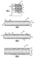
- Figure 2 illustrates a cross-section through one of the fins 22.
- the fin 22 includes a first protective layer 32, a second protective layer 34, and a heat transfer layer 36 bonded between the first protective layer 32 and the second protective layer 34.
- the fin 22 is a composite wherein the first protective layer 32 and the second protective layer 34 provide a desired degree of corrosion resistance to the working fluid and/or high temperature environment, and the heat transfer layer 36 provides a desirable degree of thermal conductivity for enhanced heat exchange between the working fluids.
- the first protective layer 32 and the second protective layer 34 may be comprised of metallic materials having a desired degree of corrosion and temperature resistance.
- the first protective layer 32 and the second protective layer 34 may be formed from any metallic material this is known to be more corrosion resistant than the heat transfer layer 36.
- the first protective layer 32 and the second protective layer 34 are stainless steel (e.g., steel having grater than about 11.5 wt% of chromium).
- the first protective layer 32, the second protective layer 34, and the heat transfer layer 36 may be of any desired thickness, depending for instance on the particular design of the heat transfer device 10, degree of desired corrosion protection, degree of desired thermal conductivity, degree of desired strength, or other design factors.
- each of the first protective layer 32, the second protective layer 34, and the heat transfer layer 36 is about 1 mil - 15 mils thick (25.4 - 381 micrometers).
- the heat transfer layer 36 is thicker than each of the first protective layer 32 and the second protective layer 34 by a factor of about three.
- the heat transfer layer 36 is about 15 mils thick and each of the first protective layer 32 and the second protective layer 34 is about 5 mils (127 micrometers) thick.
- the term "about” as used in this description relative to thicknesses, compositions, or other values refers to possible variation in the given value, such as normally accepted variations or tolerances in the art.
- the heat transfer layer 36 may be formed from any type of material having a desired level of thermal conductivity.
- the heat transfer layer 36 may have a thermal conductivity that is higher than the thermal conductivity of the first protective layer 32 and the second protective layer 34.
- the first protective layer 32 and the second protective layer 34 protect the less corrosion resistant heat transfer layer 36, and the more thermally conductive heat transfer layer 36 bears a greater degree of the thermal transfer function of the fin 22 than the first protective layer 32 and the second protective layer 34.
- the heat transfer layer 36 is comprised of a metal matrix composite.
- the metal matrix composite may include aluminum oxide reinforcement 38 dispersed within a copper matrix 40, although other types of metal matrix composites may alternatively be used.
- the aluminum oxide reinforcement 38 reinforces the copper matrix 40 to provide a relatively high strength compared to pure copper.
- the copper matrix 40 provides the benefit of relatively high thermal conductivity relative to a pure copper.
- the copper matrix 40 may be any of a variety of different compositions.
- the copper matrix 40 may be substantially pure copper that may include trace impurities that do not materially affect the properties of the copper or elements that are unmeasured or undetectable in the copper.
- the metal matrix composite 36 provides resistance to temperatures of 1000°F (538°C) and possibly up to 1500°F (816°C).
- common copper alloys, or precipitation strengthened copper alloys are limited to use below 600°F - 800°F (316°C - 427°C) since the age hardening temperature is typically in this range.
- the aluminum oxide reinforcement 38 is not a product of precipitation hardening, and therefore is not subject to the same solution/precipitation mechanisms that form a precipitation strengthened alloy.
- the aluminum oxide reinforcement 38 is inert at the age-hardening temperatures and the metal matrix composite 36 is thereby able to withstand temperatures of 1000°F (538°C) and possibly up to 1500°F (816°C).
- the composition of the metal matrix composite 36 relative to the amount of aluminum oxide reinforcement 38 may vary depending upon the desired properties of the metal matrix composite 36.
- the metal matrix composite 36 may include up to about 2.0wt% of the aluminum oxide reinforcement 38.
- the metal matrix composite includes about 0.3wt% to 1.5wt% of the aluminum oxide reinforcement 38.
- selecting a lower amount of the aluminum oxide reinforcement 38 would provide the metal matrix composite 36 with relatively higher thermal conductivity and relatively lower strength, while selecting a higher amount of the aluminum oxide reinforcement 38 would provide relatively higher strength but relatively lower thermal conductivity.
- the structure of the fin 22 may be formed using any of a variety of different processing methods.
- the fin 22 may be formed using roll bonding, diffusion bonding, explosion bonding, or other types of bonding/forming methods.
- the heat transfer layer 36 may be positioned between the first protective layer 32 and the second protective layer 34 and then fed into a rolling mill. Rollers of the rolling mill compress the first protective layer 32, the second protective layer 34, and the heat transfer layer 36 together under a relatively high pressure. The pressure causes mechanical deformation that physically locks the first protective layer 32, the second protective layer 34, and the heat transfer layer 36 together.
- the first protective layer 32, the second protective layer 34, and the heat transfer layer 36 may be heated to cause diffusion bonding.
- the first protective layer 32 and the second protective layer 34 may be formed on the heat transfer layer 36 through a coating process, such as explosion bonding or spraying.
- edges 50 of the fin 22 may be left exposed to the surrounding environment.
- a cladding 52 may be a braze alloy that is also used to bond the fins 22 to the parting sheets 16.
- the braze alloy such as a copper-based braze alloy, may be forming using known brazing techniques during a brazing process to bond the fins 22 to the parting sheets 16.
- the cladding 52 may be a nickel-based material for providing additional corrosion resistance to the fin 22. The nickel-based material may be applied using known coating techniques.
- Figure 4 illustrates another embodiment of a heat transfer device 122.
- like reference numerals designate like elements where appropriate, and reference numerals with the addition of 100 or multiples thereof designate modified elements.
- the modified elements incorporate the same features and benefits of the corresponding modified elements, except where stated otherwise.
- the fin 122 is similar to the fin 22 of the previous examples but includes a first diffusion barrier layer 60 between the first protective layer 32 and the heat transfer layer 36, and a second diffusion barrier layer 62 between the second protective layer 34 and the heat transfer layer 36.
- the fin 122 may reach temperatures that can cause inter-diffusion among the first protective layer 32, the second protective layer 34, and the heat transfer layer 36. Inter-diffusion may effectively alter the chemical composition of the heat transfer layer 36 and thereby diminish the thermal conductivity of the heat transfer layer 36.
- the first diffusion barrier layer 60 and the second diffusion barrier layer 62 limit inter-diffusion and provide the benefit of maintaining the thermal conductivity of the heat transfer layer 36.
- the first diffusion barrier layer 60 and the second diffusion barrier layer 62 may be formed from any type of material suitable for blocking inter-diffusion.
- the selected material may also have limited diffusivity into the first protective layer 32, the second protective layer 34, and heat transfer layer 36.
- the first diffusion barrier layer 60 and the second diffusion barrier layer 62 are generally high melting point materials relative to the materials used for the other layers.
- the first diffusion barrier layer 60 and the second diffusion barrier layer 62 may be formed from a ceramic material or a refractory metal.
- the ceramic material may include a nitride or a carbonitride, such as titanium nitride or titanium carbonitride.
- the refractory metal may include titanium, niobium, tungsten, platinum, rhenium, tantalum, chromium, molybdenum, or combinations thereof.
- the material for the first diffusion barrier layer 60 and the second diffusion barrier layer 62 may be selected based on the method used to form the fins 122.
- one or more of the refractory metals may be selected because of ductility if the fins 122 are formed using roll bonding and subsequently bent into the final desired shape.
- niobium is relatively inexpensive and may exhibit a desirable degree of ductility that avoids cracking when rolled or otherwise mechanically deformed.
- any of the refractory metals may be used. Ceramic materials may also be used where ductility is not needed for the forming process, such as in a coating process.
- the disclosed example fins 22 and 122 provide a desirable combination of high strength, high thermal conductivity, and high temperature resistance.
- the first protective layer 32 and the second protective layer 34 provide the fin 22 or 122 with excellent corrosion protection
- the heat transfer layer 36 provides the fin 22 or 122 with excellent thermal conductivity.
Landscapes
- Engineering & Computer Science (AREA)
- Mechanical Engineering (AREA)
- Physics & Mathematics (AREA)
- General Engineering & Computer Science (AREA)
- Chemical & Material Sciences (AREA)
- Thermal Sciences (AREA)
- Materials Engineering (AREA)
- Organic Chemistry (AREA)
- Metallurgy (AREA)
- Dispersion Chemistry (AREA)
- Laminated Bodies (AREA)
- Heat-Exchange Devices With Radiators And Conduit Assemblies (AREA)
- Cooling Or The Like Of Semiconductors Or Solid State Devices (AREA)
- Other Surface Treatments For Metallic Materials (AREA)
Abstract
Description
- This disclosure relates to heat transfer devices and, more particularly, to a heat transfer device having high strength, high thermal conductivity, and high temperature resistance.
- Heat transfer devices, such as heat exchangers, may operate at relatively high temperatures while in contact with corrosive fluids. For example, the components of the heat transfer device may be formed from an age-hardened copper alloy that generally provides a desired degree of strength and corrosion resistance up to a threshold temperature of about 600°F - 800°F (316°C - 427°C). Above the threshold temperature range, precipitants that contribute to the strength may coarsen and subsequently diminish the strength and/or resistance to corrosion.
- Although copper alloys are effective in many heat transfer devices, there may be a desire in some applications for even greater strength and thermal conductivity at higher temperature conditions. Replacement alloys having higher temperature resistance, strength, and corrosion resistance have been considered, but such alloys have lower thermal conductivity than copper and do not meet desired performance demands. Other potential replacement alloys having higher thermal conductivity do not have the desired degree of strength and corrosion resistance. Therefore, there is a need for a thermal transfer device having enhanced strength, corrosion resistance, and temperature resistance characteristics.
- The disclosed examples and variations of heat transfer devices according to the present invention are intended to provide a desirable combination of high strength, high thermal conductivity, and high temperature resistance that has not been available with prior arrangements.
- For example, one heat transfer apparatus includes a first protective layer of a first metallic material, a second protective layer of a second metallic material, and a heat transfer layer bonded between the first protective layer and the second protective layer. The heat transfer layer is made of a metal matrix composite that provides relatively high strength and thermal conductivity, while the first and second protective layers provide relatively high corrosion resistance.
- In some examples, the first and second protective layers are made of stainless steel and the metal matrix composite includes aluminum oxide reinforcement dispersed within a copper matrix. Additionally, a diffusion barrier layer may be included between each of the protective layers and the heat transfer layer to control diffusion. The diffusion barrier layers may be made of a refractory material.
- The disclosed heat transfer apparatus may be manufactured using any of a variety of different processing methods that include bonding the first protective layer of the first metallic material and the second protective material of the second metallic material to the heat transfer layer.
- Certain preferred embodiments of the present invention will now be described in greater detail by way of example only and with reference to the accompanying drawings, in which:
-
Figure 1 illustrates a portion of a heat transfer device in a preferred embodiment of the present invention; -
Figure 2 illustrates a cross-section of a fin used in the heat transfer device; -
Figure 3 illustrates another preferred embodiment where the fin is provided with optional cladding on the sides; and -
Figure 4 illustrates yet another embodiment fin that may be used in the preferred heat transfer device of the present invention. -
Figure 1 illustrates a portion of an example heat transfer apparatus ordevice 10. It is to be understood that although a particular type and design of theheat transfer device 10 is shown in this example, the examples herein may also be applied to other types of heat transfer devices and designs. In this example, theheat transfer device 10 includesalternating flow channels parting sheets 16. Theflow channels closure bars 18 and on the sides byend sheets 20. Fins 22 extend within each of theflow channels flow channels fins 22 facilitate heat transfer between the working fluids to selectively heat or cool one of the working fluids. - As can be appreciated, one or both of the working fluids may be corrosive and operate at a temperature of approximately 1000°F - 1500°F (538°C - 816°C). In this regard, the
fins 22 have the characteristics of high strength, high thermal conductivity, and high temperature resistance to provide an overall benefit in theheat transfer device 10 of greater heat exchanging capacity or lower weight/volume for a given heat exchanging capacity. -
Figure 2 illustrates a cross-section through one of thefins 22. In this example, thefin 22 includes a firstprotective layer 32, a secondprotective layer 34, and aheat transfer layer 36 bonded between the firstprotective layer 32 and the secondprotective layer 34. Thus, thefin 22 is a composite wherein the firstprotective layer 32 and the secondprotective layer 34 provide a desired degree of corrosion resistance to the working fluid and/or high temperature environment, and theheat transfer layer 36 provides a desirable degree of thermal conductivity for enhanced heat exchange between the working fluids. - The first
protective layer 32 and the secondprotective layer 34 may be comprised of metallic materials having a desired degree of corrosion and temperature resistance. For example, the firstprotective layer 32 and the secondprotective layer 34 may be formed from any metallic material this is known to be more corrosion resistant than theheat transfer layer 36. In one example, the firstprotective layer 32 and the secondprotective layer 34 are stainless steel (e.g., steel having grater than about 11.5 wt% of chromium). - The first
protective layer 32, the secondprotective layer 34, and theheat transfer layer 36 may be of any desired thickness, depending for instance on the particular design of theheat transfer device 10, degree of desired corrosion protection, degree of desired thermal conductivity, degree of desired strength, or other design factors. In some examples, each of the firstprotective layer 32, the secondprotective layer 34, and theheat transfer layer 36 is about 1 mil - 15 mils thick (25.4 - 381 micrometers). In a further example, theheat transfer layer 36 is thicker than each of the firstprotective layer 32 and the secondprotective layer 34 by a factor of about three. In a further example, theheat transfer layer 36 is about 15 mils thick and each of the firstprotective layer 32 and the secondprotective layer 34 is about 5 mils (127 micrometers) thick. The term "about" as used in this description relative to thicknesses, compositions, or other values refers to possible variation in the given value, such as normally accepted variations or tolerances in the art. - The
heat transfer layer 36 may be formed from any type of material having a desired level of thermal conductivity. For instance, theheat transfer layer 36 may have a thermal conductivity that is higher than the thermal conductivity of the firstprotective layer 32 and the secondprotective layer 34. Thus, the firstprotective layer 32 and the secondprotective layer 34 protect the less corrosion resistantheat transfer layer 36, and the more thermally conductiveheat transfer layer 36 bears a greater degree of the thermal transfer function of thefin 22 than the firstprotective layer 32 and the secondprotective layer 34. - In one example, the
heat transfer layer 36 is comprised of a metal matrix composite. The metal matrix composite may includealuminum oxide reinforcement 38 dispersed within acopper matrix 40, although other types of metal matrix composites may alternatively be used. Thealuminum oxide reinforcement 38 reinforces thecopper matrix 40 to provide a relatively high strength compared to pure copper. Thecopper matrix 40 provides the benefit of relatively high thermal conductivity relative to a pure copper. - The
copper matrix 40 may be any of a variety of different compositions. For instance, thecopper matrix 40 may be substantially pure copper that may include trace impurities that do not materially affect the properties of the copper or elements that are unmeasured or undetectable in the copper. - The
metal matrix composite 36 provides resistance to temperatures of 1000°F (538°C) and possibly up to 1500°F (816°C). For instance, common copper alloys, or precipitation strengthened copper alloys are limited to use below 600°F - 800°F (316°C - 427°C) since the age hardening temperature is typically in this range. However, thealuminum oxide reinforcement 38 is not a product of precipitation hardening, and therefore is not subject to the same solution/precipitation mechanisms that form a precipitation strengthened alloy. Thus, thealuminum oxide reinforcement 38 is inert at the age-hardening temperatures and themetal matrix composite 36 is thereby able to withstand temperatures of 1000°F (538°C) and possibly up to 1500°F (816°C). - The composition of the
metal matrix composite 36 relative to the amount ofaluminum oxide reinforcement 38 may vary depending upon the desired properties of themetal matrix composite 36. For instance, themetal matrix composite 36 may include up to about 2.0wt% of thealuminum oxide reinforcement 38. In a further example, the metal matrix composite includes about 0.3wt% to 1.5wt% of thealuminum oxide reinforcement 38. Generally, selecting a lower amount of thealuminum oxide reinforcement 38 would provide themetal matrix composite 36 with relatively higher thermal conductivity and relatively lower strength, while selecting a higher amount of thealuminum oxide reinforcement 38 would provide relatively higher strength but relatively lower thermal conductivity. - The structure of the
fin 22 may be formed using any of a variety of different processing methods. For instance, thefin 22 may be formed using roll bonding, diffusion bonding, explosion bonding, or other types of bonding/forming methods. For instance, if roll bonding is used, theheat transfer layer 36 may be positioned between the firstprotective layer 32 and the secondprotective layer 34 and then fed into a rolling mill. Rollers of the rolling mill compress the firstprotective layer 32, the secondprotective layer 34, and theheat transfer layer 36 together under a relatively high pressure. The pressure causes mechanical deformation that physically locks the firstprotective layer 32, the secondprotective layer 34, and theheat transfer layer 36 together. Alternatively, the firstprotective layer 32, the secondprotective layer 34, and theheat transfer layer 36 may be heated to cause diffusion bonding. In other examples, the firstprotective layer 32 and the secondprotective layer 34 may be formed on theheat transfer layer 36 through a coating process, such as explosion bonding or spraying. - As can be appreciated from
Figure 2 ,edges 50 of thefin 22 may be left exposed to the surrounding environment. However, in some examples, it may be desirable to seal the edges as shown inFigure 3 with acladding 52. For instance, thecladding 52 may be a braze alloy that is also used to bond thefins 22 to theparting sheets 16. The braze alloy, such as a copper-based braze alloy, may be forming using known brazing techniques during a brazing process to bond thefins 22 to theparting sheets 16. Alternatively, thecladding 52 may be a nickel-based material for providing additional corrosion resistance to thefin 22. The nickel-based material may be applied using known coating techniques. -
Figure 4 illustrates another embodiment of aheat transfer device 122. In this disclosure like reference numerals designate like elements where appropriate, and reference numerals with the addition of 100 or multiples thereof designate modified elements. The modified elements incorporate the same features and benefits of the corresponding modified elements, except where stated otherwise. In this example, thefin 122 is similar to thefin 22 of the previous examples but includes a firstdiffusion barrier layer 60 between the firstprotective layer 32 and theheat transfer layer 36, and a seconddiffusion barrier layer 62 between the secondprotective layer 34 and theheat transfer layer 36. - During prolonged operation at relatively high temperatures, the
fin 122 may reach temperatures that can cause inter-diffusion among the firstprotective layer 32, the secondprotective layer 34, and theheat transfer layer 36. Inter-diffusion may effectively alter the chemical composition of theheat transfer layer 36 and thereby diminish the thermal conductivity of theheat transfer layer 36. In this regard, the firstdiffusion barrier layer 60 and the seconddiffusion barrier layer 62 limit inter-diffusion and provide the benefit of maintaining the thermal conductivity of theheat transfer layer 36. - The first
diffusion barrier layer 60 and the seconddiffusion barrier layer 62 may be formed from any type of material suitable for blocking inter-diffusion. The selected material may also have limited diffusivity into the firstprotective layer 32, the secondprotective layer 34, andheat transfer layer 36. For instance, the firstdiffusion barrier layer 60 and the seconddiffusion barrier layer 62 are generally high melting point materials relative to the materials used for the other layers. In some examples, the firstdiffusion barrier layer 60 and the seconddiffusion barrier layer 62 may be formed from a ceramic material or a refractory metal. The ceramic material may include a nitride or a carbonitride, such as titanium nitride or titanium carbonitride. As can be appreciated, other types of ceramic materials may also be used. The refractory metal may include titanium, niobium, tungsten, platinum, rhenium, tantalum, chromium, molybdenum, or combinations thereof. - In some examples, the material for the first
diffusion barrier layer 60 and the seconddiffusion barrier layer 62 may be selected based on the method used to form thefins 122. For instance, one or more of the refractory metals may be selected because of ductility if thefins 122 are formed using roll bonding and subsequently bent into the final desired shape. In a further example, niobium is relatively inexpensive and may exhibit a desirable degree of ductility that avoids cracking when rolled or otherwise mechanically deformed. In fin designs that have high angle bends or no bends any of the refractory metals may be used. Ceramic materials may also be used where ductility is not needed for the forming process, such as in a coating process. - Thus, the disclosed
example fins protective layer 32 and the secondprotective layer 34 provide thefin heat transfer layer 36 provides thefin - Although a combination of features is shown in the illustrated examples, not all of them need to be combined to realize the benefits of various embodiments of this disclosure. In other words, a system designed according to an embodiment of this disclosure will not necessarily include all of the features shown in any one of the Figures or all of the portions schematically shown in the Figures. Moreover, selected features of one example embodiment may be combined with selected features of other example embodiments.
- The preceding description is exemplary rather than limiting in nature. Variations and modifications to the disclosed examples may become apparent to those skilled in the art that do not necessarily depart from the essence of this disclosure. The scope of legal protection given to this disclosure can only be determined by studying the following claims.
Claims (15)
- A heat transfer apparatus comprising:a first protective layer (32) comprised of a first metallic material;a second protective layer (34) comprised of a second metallic material; anda heat transfer layer (36) bonded between the first protective layer and the second protective layer, the heat transfer layer being comprised of a metal matrix composite.
- The heat transfer apparatus as recited in claim 1, wherein the metal matrix composite is comprised of aluminum oxide reinforcement (38) dispersed within a copper matrix (40).
- The heat transfer apparatus as recited in claim 2, wherein the metal matrix composite (36) includes up to about 2.0wt% of the aluminum oxide reinforcement (38), and more preferably the metal matrix composite includes about 0.3wt%-1.5wt% of the aluminum oxide reinforcement.
- The heat transfer apparatus as recited in claim 2 or 3, wherein the copper (40) is substantially pure.
- The heat transfer apparatus as recited in any preceding claim, wherein the first metallic material (32) and the second metallic material (34) are stainless steel.
- The heat transfer apparatus as recited in any preceding claim, further comprising a cladding (52) on edges of the first protective layer (32), the second protective layer (34), and the heat transfer layer (36), more preferably, wherein the cladding (52) is a braze alloy, and wherein preferably the cladding (52) is a nickel-based material.
- The heat transfer apparatus as recited in any preceding claim, further comprising a first diffusion barrier layer (60) between the first protective layer (32) and the heat transfer layer (36), and a second diffusion barrier layer (62) between the second protective layer (34) and the heat transfer layer, and preferably wherein the first diffusion barrier layer (60) and the second diffusion barrier layer (62) are each comprised of a refractory material.
- A heat transfer apparatus comprising:a first stainless steel layer (32);a second stainless steel layer (34);a heat transfer layer (36) bonded between the first stainless steel layer and the second stainless steel layer, the heat transfer layer being comprised of a metal matrix composite having an aluminum oxide reinforcement (38) dispersed within a copper matrix (40);a first diffusion barrier layer (60) between the first stainless steel layer and the heat transfer layer; anda second diffusion barrier layer (62) between the second stainless steel layer and the heat transfer layer, the first diffusion barrier layer and the second diffusion barrier, each diffusion barrier layer being comprised of a refractory material.
- The heat transfer apparatus as recited in claim 8, wherein the metal matrix composite (36) includes up to about 2.0wt% of the aluminum oxide reinforcement (38), and more preferably the metal matrix composite includes about 0.3-1.5wt% of the aluminum oxide reinforcement.
- The heat transfer apparatus as recited in claim 8 or 9, wherein the refractory material (60, 62) is a ceramic material.
- The heat transfer apparatus as recited in claim 10, wherein the ceramic material includes at least one of a nitride or a carbonitride.
- The heat transfer apparatus as recited in any of claims 8 to 11, wherein the refractory material is metallic material selected from the group consisting of titanium, niobium, tungsten, platinum, rhenium, tantalum, chromium, molybdenum, and combinations thereof.
- The heat transfer apparatus as recited in claim 12, wherein the refractory material is niobium.
- A method of manufacturing a heat transfer apparatus, comprising:bonding a first protective layer (32) comprised of a first metallic material and a second protective layer (34) comprised of a second metallic material to a heat transfer layer (36) comprised of a metal matrix composite.
- The method as recited in claim 14, further including bonding a first diffusion barrier layer (60) between the first protective layer (32) and the heat transfer layer (36), and bonding a second diffusion barrier layer (62) between the second protective layer (34) and the heat transfer layer, the first diffusion barrier layer and the second diffusion barrier each being comprised of a refractory material.
Applications Claiming Priority (1)
| Application Number | Priority Date | Filing Date | Title |
|---|---|---|---|
| US12/119,543 US8129036B2 (en) | 2008-05-13 | 2008-05-13 | High strength and high thermal conductivity heat transfer apparatus |
Publications (3)
| Publication Number | Publication Date |
|---|---|
| EP2119992A2 true EP2119992A2 (en) | 2009-11-18 |
| EP2119992A3 EP2119992A3 (en) | 2013-08-21 |
| EP2119992B1 EP2119992B1 (en) | 2014-06-18 |
Family
ID=40954466
Family Applications (1)
| Application Number | Title | Priority Date | Filing Date |
|---|---|---|---|
| EP09251304.3A Active EP2119992B1 (en) | 2008-05-13 | 2009-05-13 | High strength and high thermal conductivity heat transfer apparatus |
Country Status (3)
| Country | Link |
|---|---|
| US (1) | US8129036B2 (en) |
| EP (1) | EP2119992B1 (en) |
| JP (1) | JP5076066B2 (en) |
Families Citing this family (6)
| Publication number | Priority date | Publication date | Assignee | Title |
|---|---|---|---|---|
| US9279626B2 (en) * | 2012-01-23 | 2016-03-08 | Honeywell International Inc. | Plate-fin heat exchanger with a porous blocker bar |
| BR112018070865B1 (en) * | 2016-04-12 | 2022-08-30 | Gränges Ab | BRAZING SHEET, COATING PLATE AND MANUFACTURING METHOD OF A BRAZING SHEET |
| EP3473961B1 (en) | 2017-10-20 | 2020-12-02 | Api Heat Transfer, Inc. | Heat exchanger |
| USD1078948S1 (en) * | 2021-01-18 | 2025-06-10 | Baltimore Aircoil Company, Inc. | Indirect heat exchanger tube controlled wrinkle bend |
| CA3208308A1 (en) | 2021-01-18 | 2022-07-21 | Baltimore Aircoil Company, Inc. | Indirect heat exchanger pressure vessel with controlled wrinkle bends |
| USD1046085S1 (en) | 2021-10-22 | 2024-10-08 | Baltimore Aircoil Company, Inc. | Heat exchanger tube |
Family Cites Families (32)
| Publication number | Priority date | Publication date | Assignee | Title |
|---|---|---|---|---|
| GB779769A (en) | 1954-07-06 | 1957-07-24 | Griscom Russell Co | Improvements in or relating to heat exchangers and materials therefor |
| US2807074A (en) * | 1955-09-27 | 1957-09-24 | Griscom Russell Co | Manufacture of brazed finned tubing and the like |
| US3053511A (en) * | 1957-11-15 | 1962-09-11 | Gen Motors Corp | Clad alloy metal for corrosion resistance and heat exchanger made therefrom |
| US3886647A (en) * | 1971-07-07 | 1975-06-03 | Trw Inc | Method of making erosion resistant articles |
| CH602330A5 (en) * | 1976-08-26 | 1978-07-31 | Bbc Brown Boveri & Cie | |
| ES8308738A1 (en) * | 1981-09-08 | 1983-10-16 | Johnson Matthey Plc | PRODUCTION METHOD OF A COMPOSITE METALLIC MATERIAL. |
| JPS6376774A (en) * | 1986-09-18 | 1988-04-07 | Sumitomo Light Metal Ind Ltd | Heat resistant high electrical conductivity copper alloy clad material |
| JPH0318871Y2 (en) * | 1987-04-30 | 1991-04-22 | ||
| JPS6422481A (en) * | 1987-07-15 | 1989-01-25 | Hitachi Cable | Clad spring material for conduction |
| JPH01252739A (en) * | 1988-03-31 | 1989-10-09 | Toshiba Corp | Heat-resisting composite body |
| US5063117A (en) * | 1988-12-27 | 1991-11-05 | The Furukawa Electric Co., Ltd. | Copper fin material for heat-exchanger and method of producing the same |
| US5001299A (en) * | 1989-04-17 | 1991-03-19 | Explosive Fabricators, Inc. | Explosively formed electronic packages |
| JPH0284324A (en) * | 1989-08-22 | 1990-03-26 | Mitsubishi Steel Mfg Co Ltd | Heat-resistant, corrosion-resistant clad section steel |
| US6277499B1 (en) * | 1992-04-23 | 2001-08-21 | United Technologies Corporation | Oxidation resistant coatings for copper |
| US5308311A (en) * | 1992-05-01 | 1994-05-03 | Robert F. Shaw | Electrically heated surgical blade and methods of making |
| US5564496A (en) * | 1994-11-01 | 1996-10-15 | United Technologies Corporation | Composite parting sheet |
| WO1997025577A1 (en) | 1996-01-11 | 1997-07-17 | Fintube Limited Partnership | Composite metal fin and method for producing the same |
| US5895696A (en) * | 1996-07-01 | 1999-04-20 | Alyn Corporation | Metal-clad ceramic-metal matrix composites for magnetic disk substrates for hard disk drives |
| JP3705655B2 (en) * | 1996-08-07 | 2005-10-12 | 日本原子力研究所 | Heat-resistant and highly heat-conductive cooling pipe |
| JP3197835B2 (en) * | 1997-02-03 | 2001-08-13 | 日本碍子株式会社 | Composite joint of beryllium, copper alloy and stainless steel and composite joint method |
| JP2000246549A (en) * | 1999-02-25 | 2000-09-12 | Toshiba Corp | Joining structure and joining method for dissimilar metal materials |
| US20020006526A1 (en) * | 1999-10-11 | 2002-01-17 | Polese Frank J. | Aluminum silicon carbide and copper clad material and manufacturing process |
| JP2001240933A (en) * | 2000-02-29 | 2001-09-04 | Daido Metal Co Ltd | Copper-based sliding material, its manufacturing method and sliding bearing material, its manufacturing method |
| US6593010B2 (en) * | 2001-03-16 | 2003-07-15 | Hood & Co., Inc. | Composite metals and method of making |
| US20040018314A1 (en) * | 2002-07-25 | 2004-01-29 | Carrier Corporation | Primer adhesive for laminated condensing heat exchangers |
| US20040250422A1 (en) * | 2003-06-16 | 2004-12-16 | Carrier Corporation | Coating of heat exchanger tubes |
| US7625520B2 (en) * | 2003-11-18 | 2009-12-01 | Dwa Technologies, Inc. | Manufacturing method for high yield rate of metal matrix composite sheet production |
| US7293602B2 (en) * | 2005-06-22 | 2007-11-13 | Holtec International Inc. | Fin tube assembly for heat exchanger and method |
| US20070154731A1 (en) * | 2005-12-29 | 2007-07-05 | Serguei Vatchiants | Aluminum-based composite materials and methods of preparation thereof |
| JP2008024561A (en) * | 2006-07-24 | 2008-02-07 | Toshiba Corp | Ceramic-metal bonded component and method for manufacturing the same |
| US20090104470A1 (en) * | 2007-10-23 | 2009-04-23 | Hideki Suzuki | Production method for metal matrix composite material |
| US8142425B2 (en) * | 2007-10-30 | 2012-03-27 | Hemostatix Medical Techs, LLC | Hemostatic surgical blade, system and method of blade manufacture |
-
2008
- 2008-05-13 US US12/119,543 patent/US8129036B2/en active Active
-
2009
- 2009-05-13 EP EP09251304.3A patent/EP2119992B1/en active Active
- 2009-05-13 JP JP2009116629A patent/JP5076066B2/en not_active Expired - Fee Related
Non-Patent Citations (1)
| Title |
|---|
| None |
Also Published As
| Publication number | Publication date |
|---|---|
| US8129036B2 (en) | 2012-03-06 |
| JP2009276058A (en) | 2009-11-26 |
| US20090283250A1 (en) | 2009-11-19 |
| EP2119992B1 (en) | 2014-06-18 |
| EP2119992A3 (en) | 2013-08-21 |
| JP5076066B2 (en) | 2012-11-21 |
Similar Documents
| Publication | Publication Date | Title |
|---|---|---|
| EP2119992B1 (en) | High strength and high thermal conductivity heat transfer apparatus | |
| JP5960748B2 (en) | High strength and high strength brazing sandwich material | |
| CN107428128B (en) | Multilayer aluminum brazing sheet material | |
| TWI502086B (en) | Copper alloy sheet and method for producing same | |
| KR101811332B1 (en) | Corrosion resistant aluminium alloy for heat exchanger tube, manufacturing method for tube or pipe using the aluminium alloy, and heat exchanger using the same | |
| JP6452626B2 (en) | Aluminum alloy clad material and method for producing the same, heat exchanger using the aluminum alloy clad material, and method for producing the same | |
| JP5913853B2 (en) | Aluminum alloy brazing sheet and method for producing the same | |
| US20130315660A1 (en) | Pressure resistant and corrosion resistant copper alloy, brazed structure, and method of manufacturing brazed structure | |
| EP1436438A1 (en) | Aluminium alloy for making fin stock material | |
| EP3321384B1 (en) | Aluminum alloy cladding material, manufacturing method therefor, and heat exchanger using said aluminum alloy cladding material | |
| KR101979531B1 (en) | Copper alloy plate and heat dissipation parts for heat dissipation parts | |
| JP6868383B2 (en) | Manufacturing method of aluminum alloy brazing sheet | |
| DK2898107T3 (en) | ALUMINUM ALLOY COMPOSITION AND PROCEDURE | |
| EP3321385A1 (en) | Aluminum alloy cladding material and manufacturing method therefor | |
| CN111065753B (en) | Aluminum alloy brazing sheet for heat exchanger | |
| NL1016977C2 (en) | Aluminum alloys with optimum combinations of formability, corrosion resistance and hot processability, and methods of application. | |
| CN108290251A (en) | brazing sheet | |
| CN110997958B (en) | Aluminum alloy brazing sheet for heat exchanger | |
| US10557188B2 (en) | Aluminum alloy composition and method | |
| EP0587307B1 (en) | Aluminium alloys | |
| EP2836785B1 (en) | Aluminum alloy tube-fin heat exchanger | |
| JP6351205B2 (en) | High corrosion resistance aluminum alloy brazing sheet | |
| JPH08143997A (en) | Aluminum alloy fin material and brazing sheet for low temperature brazing, method for manufacturing aluminum alloy heat exchanger, and aluminum alloy heat exchanger | |
| CN114173984A (en) | Aluminum alloy brazing sheet and method for producing same | |
| CN112955574A (en) | Aluminum alloy brazing sheet and method for producing same |
Legal Events
| Date | Code | Title | Description |
|---|---|---|---|
| PUAI | Public reference made under article 153(3) epc to a published international application that has entered the european phase |
Free format text: ORIGINAL CODE: 0009012 |
|
| AK | Designated contracting states |
Kind code of ref document: A2 Designated state(s): AT BE BG CH CY CZ DE DK EE ES FI FR GB GR HR HU IE IS IT LI LT LU LV MC MK MT NL NO PL PT RO SE SI SK TR |
|
| RAP1 | Party data changed (applicant data changed or rights of an application transferred) |
Owner name: HAMILTON SUNDSTRAND SPACE SYSTEMS INTERNATIONAL, I |
|
| PUAL | Search report despatched |
Free format text: ORIGINAL CODE: 0009013 |
|
| AK | Designated contracting states |
Kind code of ref document: A3 Designated state(s): AT BE BG CH CY CZ DE DK EE ES FI FR GB GR HR HU IE IS IT LI LT LU LV MC MK MT NL NO PL PT RO SE SI SK TR |
|
| AX | Request for extension of the european patent |
Extension state: AL BA RS |
|
| RIC1 | Information provided on ipc code assigned before grant |
Ipc: F28F 19/06 20060101ALI20130715BHEP Ipc: F28F 21/08 20060101ALI20130715BHEP Ipc: F28D 9/00 20060101AFI20130715BHEP Ipc: B32B 15/01 20060101ALI20130715BHEP |
|
| 17P | Request for examination filed |
Effective date: 20131120 |
|
| RBV | Designated contracting states (corrected) |
Designated state(s): AT BE BG CH CY CZ DE DK EE ES FI FR GB GR HR HU IE IS IT LI LT LU LV MC MK MT NL NO PL PT RO SE SI SK TR |
|
| GRAP | Despatch of communication of intention to grant a patent |
Free format text: ORIGINAL CODE: EPIDOSNIGR1 |
|
| INTG | Intention to grant announced |
Effective date: 20140109 |
|
| GRAS | Grant fee paid |
Free format text: ORIGINAL CODE: EPIDOSNIGR3 |
|
| GRAA | (expected) grant |
Free format text: ORIGINAL CODE: 0009210 |
|
| RIN1 | Information on inventor provided before grant (corrected) |
Inventor name: YAWORSKI, STEPHEN A Inventor name: BERINGER, DURWOOD M Inventor name: SCHWALM, GREGORY K Inventor name: STIEBER, JESSE J Inventor name: ZACHARIAS, KENNETH J Inventor name: TADDEY, EDMUND P |
|
| AK | Designated contracting states |
Kind code of ref document: B1 Designated state(s): AT BE BG CH CY CZ DE DK EE ES FI FR GB GR HR HU IE IS IT LI LT LU LV MC MK MT NL NO PL PT RO SE SI SK TR |
|
| REG | Reference to a national code |
Ref country code: GB Ref legal event code: FG4D |
|
| REG | Reference to a national code |
Ref country code: CH Ref legal event code: EP |
|
| REG | Reference to a national code |
Ref country code: NL Ref legal event code: T3 |
|
| REG | Reference to a national code |
Ref country code: AT Ref legal event code: REF Ref document number: 673580 Country of ref document: AT Kind code of ref document: T Effective date: 20140715 |
|
| REG | Reference to a national code |
Ref country code: IE Ref legal event code: FG4D |
|
| REG | Reference to a national code |
Ref country code: DE Ref legal event code: R096 Ref document number: 602009024725 Country of ref document: DE Effective date: 20140731 |
|
| PG25 | Lapsed in a contracting state [announced via postgrant information from national office to epo] |
Ref country code: LT Free format text: LAPSE BECAUSE OF FAILURE TO SUBMIT A TRANSLATION OF THE DESCRIPTION OR TO PAY THE FEE WITHIN THE PRESCRIBED TIME-LIMIT Effective date: 20140618 Ref country code: CY Free format text: LAPSE BECAUSE OF FAILURE TO SUBMIT A TRANSLATION OF THE DESCRIPTION OR TO PAY THE FEE WITHIN THE PRESCRIBED TIME-LIMIT Effective date: 20140618 Ref country code: NO Free format text: LAPSE BECAUSE OF FAILURE TO SUBMIT A TRANSLATION OF THE DESCRIPTION OR TO PAY THE FEE WITHIN THE PRESCRIBED TIME-LIMIT Effective date: 20140918 Ref country code: GR Free format text: LAPSE BECAUSE OF FAILURE TO SUBMIT A TRANSLATION OF THE DESCRIPTION OR TO PAY THE FEE WITHIN THE PRESCRIBED TIME-LIMIT Effective date: 20140919 Ref country code: FI Free format text: LAPSE BECAUSE OF FAILURE TO SUBMIT A TRANSLATION OF THE DESCRIPTION OR TO PAY THE FEE WITHIN THE PRESCRIBED TIME-LIMIT Effective date: 20140618 |
|
| REG | Reference to a national code |
Ref country code: AT Ref legal event code: MK05 Ref document number: 673580 Country of ref document: AT Kind code of ref document: T Effective date: 20140618 |
|
| REG | Reference to a national code |
Ref country code: LT Ref legal event code: MG4D |
|
| PG25 | Lapsed in a contracting state [announced via postgrant information from national office to epo] |
Ref country code: LV Free format text: LAPSE BECAUSE OF FAILURE TO SUBMIT A TRANSLATION OF THE DESCRIPTION OR TO PAY THE FEE WITHIN THE PRESCRIBED TIME-LIMIT Effective date: 20140618 Ref country code: SE Free format text: LAPSE BECAUSE OF FAILURE TO SUBMIT A TRANSLATION OF THE DESCRIPTION OR TO PAY THE FEE WITHIN THE PRESCRIBED TIME-LIMIT Effective date: 20140618 Ref country code: HR Free format text: LAPSE BECAUSE OF FAILURE TO SUBMIT A TRANSLATION OF THE DESCRIPTION OR TO PAY THE FEE WITHIN THE PRESCRIBED TIME-LIMIT Effective date: 20140618 |
|
| PG25 | Lapsed in a contracting state [announced via postgrant information from national office to epo] |
Ref country code: ES Free format text: LAPSE BECAUSE OF FAILURE TO SUBMIT A TRANSLATION OF THE DESCRIPTION OR TO PAY THE FEE WITHIN THE PRESCRIBED TIME-LIMIT Effective date: 20140618 Ref country code: EE Free format text: LAPSE BECAUSE OF FAILURE TO SUBMIT A TRANSLATION OF THE DESCRIPTION OR TO PAY THE FEE WITHIN THE PRESCRIBED TIME-LIMIT Effective date: 20140618 Ref country code: CZ Free format text: LAPSE BECAUSE OF FAILURE TO SUBMIT A TRANSLATION OF THE DESCRIPTION OR TO PAY THE FEE WITHIN THE PRESCRIBED TIME-LIMIT Effective date: 20140618 Ref country code: PT Free format text: LAPSE BECAUSE OF FAILURE TO SUBMIT A TRANSLATION OF THE DESCRIPTION OR TO PAY THE FEE WITHIN THE PRESCRIBED TIME-LIMIT Effective date: 20141020 Ref country code: RO Free format text: LAPSE BECAUSE OF FAILURE TO SUBMIT A TRANSLATION OF THE DESCRIPTION OR TO PAY THE FEE WITHIN THE PRESCRIBED TIME-LIMIT Effective date: 20140618 Ref country code: SK Free format text: LAPSE BECAUSE OF FAILURE TO SUBMIT A TRANSLATION OF THE DESCRIPTION OR TO PAY THE FEE WITHIN THE PRESCRIBED TIME-LIMIT Effective date: 20140618 |
|
| PG25 | Lapsed in a contracting state [announced via postgrant information from national office to epo] |
Ref country code: PL Free format text: LAPSE BECAUSE OF FAILURE TO SUBMIT A TRANSLATION OF THE DESCRIPTION OR TO PAY THE FEE WITHIN THE PRESCRIBED TIME-LIMIT Effective date: 20140618 Ref country code: AT Free format text: LAPSE BECAUSE OF FAILURE TO SUBMIT A TRANSLATION OF THE DESCRIPTION OR TO PAY THE FEE WITHIN THE PRESCRIBED TIME-LIMIT Effective date: 20140618 Ref country code: IS Free format text: LAPSE BECAUSE OF FAILURE TO SUBMIT A TRANSLATION OF THE DESCRIPTION OR TO PAY THE FEE WITHIN THE PRESCRIBED TIME-LIMIT Effective date: 20141018 |
|
| REG | Reference to a national code |
Ref country code: DE Ref legal event code: R097 Ref document number: 602009024725 Country of ref document: DE |
|
| PLBE | No opposition filed within time limit |
Free format text: ORIGINAL CODE: 0009261 |
|
| STAA | Information on the status of an ep patent application or granted ep patent |
Free format text: STATUS: NO OPPOSITION FILED WITHIN TIME LIMIT |
|
| PG25 | Lapsed in a contracting state [announced via postgrant information from national office to epo] |
Ref country code: DK Free format text: LAPSE BECAUSE OF FAILURE TO SUBMIT A TRANSLATION OF THE DESCRIPTION OR TO PAY THE FEE WITHIN THE PRESCRIBED TIME-LIMIT Effective date: 20140618 Ref country code: IT Free format text: LAPSE BECAUSE OF FAILURE TO SUBMIT A TRANSLATION OF THE DESCRIPTION OR TO PAY THE FEE WITHIN THE PRESCRIBED TIME-LIMIT Effective date: 20140618 |
|
| 26N | No opposition filed |
Effective date: 20150319 |
|
| PG25 | Lapsed in a contracting state [announced via postgrant information from national office to epo] |
Ref country code: BE Free format text: LAPSE BECAUSE OF FAILURE TO SUBMIT A TRANSLATION OF THE DESCRIPTION OR TO PAY THE FEE WITHIN THE PRESCRIBED TIME-LIMIT Effective date: 20140618 |
|
| REG | Reference to a national code |
Ref country code: DE Ref legal event code: R097 Ref document number: 602009024725 Country of ref document: DE Effective date: 20150319 |
|
| PG25 | Lapsed in a contracting state [announced via postgrant information from national office to epo] |
Ref country code: SI Free format text: LAPSE BECAUSE OF FAILURE TO SUBMIT A TRANSLATION OF THE DESCRIPTION OR TO PAY THE FEE WITHIN THE PRESCRIBED TIME-LIMIT Effective date: 20140618 |
|
| REG | Reference to a national code |
Ref country code: DE Ref legal event code: R119 Ref document number: 602009024725 Country of ref document: DE |
|
| REG | Reference to a national code |
Ref country code: CH Ref legal event code: PL |
|
| GBPC | Gb: european patent ceased through non-payment of renewal fee |
Effective date: 20150513 |
|
| PG25 | Lapsed in a contracting state [announced via postgrant information from national office to epo] |
Ref country code: CH Free format text: LAPSE BECAUSE OF NON-PAYMENT OF DUE FEES Effective date: 20150531 Ref country code: LU Free format text: LAPSE BECAUSE OF FAILURE TO SUBMIT A TRANSLATION OF THE DESCRIPTION OR TO PAY THE FEE WITHIN THE PRESCRIBED TIME-LIMIT Effective date: 20150513 Ref country code: LI Free format text: LAPSE BECAUSE OF NON-PAYMENT OF DUE FEES Effective date: 20150531 Ref country code: MC Free format text: LAPSE BECAUSE OF FAILURE TO SUBMIT A TRANSLATION OF THE DESCRIPTION OR TO PAY THE FEE WITHIN THE PRESCRIBED TIME-LIMIT Effective date: 20140618 |
|
| REG | Reference to a national code |
Ref country code: IE Ref legal event code: MM4A |
|
| REG | Reference to a national code |
Ref country code: FR Ref legal event code: ST Effective date: 20160129 |
|
| PG25 | Lapsed in a contracting state [announced via postgrant information from national office to epo] |
Ref country code: IE Free format text: LAPSE BECAUSE OF NON-PAYMENT OF DUE FEES Effective date: 20150513 Ref country code: GB Free format text: LAPSE BECAUSE OF NON-PAYMENT OF DUE FEES Effective date: 20150513 Ref country code: DE Free format text: LAPSE BECAUSE OF NON-PAYMENT OF DUE FEES Effective date: 20151201 |
|
| PG25 | Lapsed in a contracting state [announced via postgrant information from national office to epo] |
Ref country code: FR Free format text: LAPSE BECAUSE OF NON-PAYMENT OF DUE FEES Effective date: 20150601 |
|
| PG25 | Lapsed in a contracting state [announced via postgrant information from national office to epo] |
Ref country code: MT Free format text: LAPSE BECAUSE OF FAILURE TO SUBMIT A TRANSLATION OF THE DESCRIPTION OR TO PAY THE FEE WITHIN THE PRESCRIBED TIME-LIMIT Effective date: 20140618 |
|
| PG25 | Lapsed in a contracting state [announced via postgrant information from national office to epo] |
Ref country code: HU Free format text: LAPSE BECAUSE OF FAILURE TO SUBMIT A TRANSLATION OF THE DESCRIPTION OR TO PAY THE FEE WITHIN THE PRESCRIBED TIME-LIMIT; INVALID AB INITIO Effective date: 20090513 Ref country code: BG Free format text: LAPSE BECAUSE OF FAILURE TO SUBMIT A TRANSLATION OF THE DESCRIPTION OR TO PAY THE FEE WITHIN THE PRESCRIBED TIME-LIMIT Effective date: 20140618 |
|
| PG25 | Lapsed in a contracting state [announced via postgrant information from national office to epo] |
Ref country code: TR Free format text: LAPSE BECAUSE OF FAILURE TO SUBMIT A TRANSLATION OF THE DESCRIPTION OR TO PAY THE FEE WITHIN THE PRESCRIBED TIME-LIMIT Effective date: 20140618 |
|
| PG25 | Lapsed in a contracting state [announced via postgrant information from national office to epo] |
Ref country code: MK Free format text: LAPSE BECAUSE OF FAILURE TO SUBMIT A TRANSLATION OF THE DESCRIPTION OR TO PAY THE FEE WITHIN THE PRESCRIBED TIME-LIMIT Effective date: 20140618 |
|
| PGFP | Annual fee paid to national office [announced via postgrant information from national office to epo] |
Ref country code: NL Payment date: 20250423 Year of fee payment: 17 |