EP2119956A1 - Headlight for a motor vehicle with a ring beam body - Google Patents
Headlight for a motor vehicle with a ring beam body Download PDFInfo
- Publication number
- EP2119956A1 EP2119956A1 EP08156261A EP08156261A EP2119956A1 EP 2119956 A1 EP2119956 A1 EP 2119956A1 EP 08156261 A EP08156261 A EP 08156261A EP 08156261 A EP08156261 A EP 08156261A EP 2119956 A1 EP2119956 A1 EP 2119956A1
- Authority
- EP
- European Patent Office
- Prior art keywords
- prisms
- light
- ring
- headlamp
- horizontal plane
- Prior art date
- Legal status (The legal status is an assumption and is not a legal conclusion. Google has not performed a legal analysis and makes no representation as to the accuracy of the status listed.)
- Granted
Links
Images

Classifications
-
- G—PHYSICS
- G02—OPTICS
- G02B—OPTICAL ELEMENTS, SYSTEMS OR APPARATUS
- G02B6/00—Light guides; Structural details of arrangements comprising light guides and other optical elements, e.g. couplings
- G02B6/0001—Light guides; Structural details of arrangements comprising light guides and other optical elements, e.g. couplings specially adapted for lighting devices or systems
-
- B—PERFORMING OPERATIONS; TRANSPORTING
- B60—VEHICLES IN GENERAL
- B60Q—ARRANGEMENT OF SIGNALLING OR LIGHTING DEVICES, THE MOUNTING OR SUPPORTING THEREOF OR CIRCUITS THEREFOR, FOR VEHICLES IN GENERAL
- B60Q1/00—Arrangement of optical signalling or lighting devices, the mounting or supporting thereof or circuits therefor
- B60Q1/0029—Spatial arrangement
- B60Q1/0041—Spatial arrangement of several lamps in relation to each other
- B60Q1/0052—Spatial arrangement of several lamps in relation to each other concentric
-
- F—MECHANICAL ENGINEERING; LIGHTING; HEATING; WEAPONS; BLASTING
- F21—LIGHTING
- F21S—NON-PORTABLE LIGHTING DEVICES; SYSTEMS THEREOF; VEHICLE LIGHTING DEVICES SPECIALLY ADAPTED FOR VEHICLE EXTERIORS
- F21S41/00—Illuminating devices specially adapted for vehicle exteriors, e.g. headlamps
- F21S41/20—Illuminating devices specially adapted for vehicle exteriors, e.g. headlamps characterised by refractors, transparent cover plates, light guides or filters
- F21S41/24—Light guides
-
- G—PHYSICS
- G02—OPTICS
- G02B—OPTICAL ELEMENTS, SYSTEMS OR APPARATUS
- G02B6/00—Light guides; Structural details of arrangements comprising light guides and other optical elements, e.g. couplings
- G02B6/0001—Light guides; Structural details of arrangements comprising light guides and other optical elements, e.g. couplings specially adapted for lighting devices or systems
- G02B6/0011—Light guides; Structural details of arrangements comprising light guides and other optical elements, e.g. couplings specially adapted for lighting devices or systems the light guides being planar or of plate-like form
- G02B6/0033—Means for improving the coupling-out of light from the light guide
- G02B6/0035—Means for improving the coupling-out of light from the light guide provided on the surface of the light guide or in the bulk of it
- G02B6/0036—2-D arrangement of prisms, protrusions, indentations or roughened surfaces
-
- G—PHYSICS
- G02—OPTICS
- G02B—OPTICAL ELEMENTS, SYSTEMS OR APPARATUS
- G02B6/00—Light guides; Structural details of arrangements comprising light guides and other optical elements, e.g. couplings
- G02B6/0001—Light guides; Structural details of arrangements comprising light guides and other optical elements, e.g. couplings specially adapted for lighting devices or systems
- G02B6/0011—Light guides; Structural details of arrangements comprising light guides and other optical elements, e.g. couplings specially adapted for lighting devices or systems the light guides being planar or of plate-like form
- G02B6/0033—Means for improving the coupling-out of light from the light guide
- G02B6/0058—Means for improving the coupling-out of light from the light guide varying in density, size, shape or depth along the light guide
- G02B6/0061—Means for improving the coupling-out of light from the light guide varying in density, size, shape or depth along the light guide to provide homogeneous light output intensity
Definitions
- the present invention relates to a headlamp for a motor vehicle with a headlamp housing, in which at least one light module is accommodated, which has a RingabstrahlSON, in which a structure of light deflecting prisms is introduced, via the coupled into the ring radiator light can be coupled out again, in a Horizontal plane and emitted in a vertical plane.
- Headlights for motor vehicles have at least one light module, wherein preferably a light module for emitting a low beam and another light module for emitting a high beam in the headlight housing are added. At least one of the light modules has a Ringabstrahl notion over which a light can be emitted, which is used either as a position light or as a daytime running light.
- the use of light emitted by the ring radiator as a brake light, as a taillight or as a flashing light both front and rear of the motor vehicle is another variant of the use of a Ringabstrahl stresses.
- the legislator is given in particular a daytime running light, with light emitting diodes increasingly used as the light source come.
- the position light or the daytime running light is emitted via radiator elements of a geometrically different design, ring-emitting bodies of manufacturer-specific design being provided which preferably extend around the exit area of the low beam or of the high beam.
- a rod-shaped radiator having a structure of light-deflecting prisms is known.
- the light is coupled via a Lichteinkoppelan gleich in the radiating and coupled over the length substantially uniformly by appropriately trained light deflecting prisms again.
- a radiating body with a homogeneous luminance distribution over the length of the rod-shaped radiating body With increasing distance from the light source, the height of the prisms increases in order to achieve a constant luminance over the length of the emission body.
- the use of such a rod-shaped radiating body is not suitable to produce a light distribution, which preferably extends in the horizontal plane without generating a loss of efficiency.
- the invention includes the technical teaching that the prisms have a variable structure over the circumference of the ring radiator, which is designed such that the extent of the emitted light field in the horizontal plane is wider than the extent of the emitted light field in the vertical plane.
- the invention is based on the idea to develop a ring radiator of a headlamp such that it is suitable for the emission of a daytime running light, the emission of the daytime running lights corresponds to the legislative requirements.
- a light field can be generated according to the invention, which is wider in the horizontal plane than in the vertical plane.
- the legislative requirement is met to provide a daytime running light, which has a rather elliptical light distribution.
- the luminances on the prisms, which are imaged on the outcoupling side of the ring radiator, are changed in their extent such that the horizontal extent of the light beams emitted from the various ring segments complies with the legal requirements.
- the quadrants of the ring radiator passing through the horizontal plane correspond to the 3 o'clock and 9 o'clock positions
- the quadrants passing through the vertical plane correspond to the 6 o'clock and 12 o'clock position, respectively .
- the prisms resemble each other in their structure at the 3 o'clock and 9 o'clock positions on the one hand and the prisms at the 6 o'clock and 12 o'clock positions on the other hand.
- An advantageous embodiment of the headlamp according to the invention has a RingabstrahlITY extending uniformly in a radius around a ring axis, wherein the prisms have a width extending in the direction of the radius.
- the width of the prisms is formed differently over the circumference of the ring radiator. Consequently, it is provided that the width of the prisms in the lateral, horizontal plane passing through the quadrant of the ring radiator is greater than the width of the prisms in the upper and lower quadrants of the ring radiator, which pass through the vertical plane.
- the prisms Based on the comparison of the dial, the prisms have a large width in the 3 o'clock and 9 o'clock positions, whereas the prisms in the 6 o'clock position and in the 12 o'clock position have a small width. If a light is coupled into the ring radiating element, the light is initially coupled out over the front side over the entire circumference of the ring radiating body Output surface.
- the prisms are arranged substantially parallel to one another, and the coupling-out angle over which the coupled-out light field extends individually for each prism also becomes smaller with prisms of smaller width. If the prisms are made wider in the quadrants of the ring radiator, which pass through the horizontal plane, the beam angle of the emitted light field is widened.
- the emission angle of the emitted light field is also reduced.
- the narrow width prisms on the quadrants that traverse the vertical plane cause a narrow emission field. If the ring radiating body with the inventive distribution of the prism structure is inserted into or onto a light module of a headlamp, an elliptical light distribution can be achieved, the main axis of the ellipse extending in the horizontal plane.
- the width of the prisms changes continuously, with the prisms circumferentially adjacent to each other, parallel to each other, and changing the width from prism to prism.
- prism groups may be provided which have a diameter jump from group to group.
- the Ringabstrahlianu has for coupling to a front coupling-out surface, through which the light from the Ringabstrahlianu can be decoupled, wherein the distance of the prisms to the ring front side varies over the circumference.
- the distance of the prisms to the front decoupling surface is selected in the lateral, the horizontal plane passing through the quadrants of the ring radiator such that the prisms are defocused to the ring front and an enlarged spread can be generated.
- the distance of the prisms to the front decoupling surface can be influenced by the penetration depth of the prisms so that the penetration depth of the saw teeth forming the prisms is deeper in the lateral quadrants passing through the horizontal plane than in the quadrants traversing the vertical plane.
- the structure of the prisms can be designed such that the scattering width of the emitted light in the lateral, horizontal plane passing through the quadrant of the Ringabstrahl stressess 10 ° to 30 ° and preferably 20 °, wherein the spread of the emitted light in the upper and lower quadrant of the ring radiator 5 ° to 15 ° and preferably 10 °.
- the latter has a light coupling connection via which the light can be coupled into the ring-emitting body.
- the coupling can take place via one and preferably two light-emitting diodes, wherein the Lichteinkoppelan usually be formed on slanted Lichteinkoppel lake.
- a first light module for emitting low-beam light and a second light module for transmitting high-beam light are received in the headlight housing, wherein the ring radiator is arranged on the first and / or on the second light module.
- the ring radiator can be used both to provide a position light and in addition to providing a daytime running lights application, the change between the function position light and the function daytime running light can be done by changing the brightness of lichteinkoppelnden LEDs.
- a headlight 1 is shown in fragmentary detail, this first comprises a headlight housing 2, which is shown from the direction of the light emission side.
- a headlight housing 2 of the headlight 1 two light modules 3 are shown, which are each designed with a ring radiator 4.
- the light modules 3 are provided, on the one hand, for providing a low beam and, on the other hand, for providing a high beam, the ring radiators 4 each extending around the light exit regions of the main light of the respective light module 3.
- FIG. 2 shows a view of a RingabstrahlMechs 4 from the direction of the front-side outcoupling surface, wherein the viewing direction from the direction of a ring axis 6, which forms the axis of rotation of the Ringabstrahllogies 4.
- the Ringabstrahlianu 4 is divided into several quadrants, each describing a pitch of 90 ° over the circumference of the RingabstrahlMechs 4. For naming the quadrants a horizontal plane H and a vertical plane V via the ring radiator 4 is shown.
- the lateral quadrants which are at the 3 o'clock and 9 o'clock positions, pass through the horizontal plane on the left and right side in the view, with the top and bottom quadrants on the 6 o'clock and on the right 12 clock position is arranged and each crosses the vertical plane V.
- the ring radiating body 4 extends symmetrically around the ring axis 6 and has a radius R.
- Distributed on the circumference of the ring radiator 4 is a Structure of prisms 5 are shown, which are executed in their structure differently depending on the position on the circumference.
- a large width B of the prisms 5 is provided, wherein the quadrants of the Ringabstrahl stressess 4, which pass through the vertical plane V, a small width B of the prisms 5 show.
- the prisms 5 have a large width B, a large extent of the emitted light field takes place in the direction of the horizontal plane.
- the prisms are arranged approximately parallel to each other and adjacent to each other, so that the course of the prisms 5 is arranged independently of the circumferential position parallel to the radius R. If the width of the prisms in the quadrants passing through the vertical plane V is reduced, the width of the light field in which the prisms decouple the light is also reduced.
- an elliptical light field is generated via a single annular radiator 4 merely by modifying the geometrical configuration of the prisms 5 with regard to their distribution over the circumference, the main axis of the ellipse extending along the horizontal plane H.
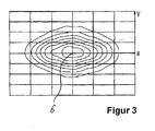
- FIG. 3 shows a diagram of the distribution of a light field, which is emitted via a Ringabstrahlö invention.
- the ring axis 6 is arranged, and the emitted light field is received from the direction of the ring axis 6.
- the extent in the horizontal plane H is approximately twice as large as the extent of the light field in the vertical plane V.
- a light field can be emitted by simply modifying the structure of the prisms 5 over the circumference of the ring emitting body 4, that meets the legal requirements of a daytime running light.
- the invention is not limited in its execution to the above-mentioned preferred embodiment. Rather, a number of variants is conceivable, which makes use of the illustrated solution even with fundamentally different types of use.
- any combination of said embodiments of the ring radiator with each other is possible to further increase the efficiency of light extraction in the form of the legally required light field.
Abstract
Description
Die vorliegende Erfindung betrifft einen Scheinwerfer für ein Kraftfahrzeug mit einem Scheinwerfergehäuse, in dem wenigstens ein Lichtmodul aufgenommen ist, das einen Ringabstrahlkörper aufweist, in den eine Struktur von lichtablenkenden Prismen eingebracht ist, über die in den Ringabstrahlkörper eingekoppeltes Licht wieder auskoppelbar ist, das in einer Horizontalebene und in einer Vertikalebene emittiert.The present invention relates to a headlamp for a motor vehicle with a headlamp housing, in which at least one light module is accommodated, which has a Ringabstrahlkörper, in which a structure of light deflecting prisms is introduced, via the coupled into the ring radiator light can be coupled out again, in a Horizontal plane and emitted in a vertical plane.
Scheinwerfer für Kraftfahrzeuge weisen wenigstens ein Lichtmodul auf, wobei bevorzugt ein Lichtmodul zur Emission eines Abblendlichtes und ein weiteres Lichtmodul zur Emission eines Fernlichtes im Scheinwerfergehäuse aufgenommen sind. Wenigstens eines der Lichtmodule besitzt einen Ringabstrahlkörper, über den ein Licht emittiert werden kann, das entweder als Positionslicht oder als Tagfahrlicht genutzt wird.Headlights for motor vehicles have at least one light module, wherein preferably a light module for emitting a low beam and another light module for emitting a high beam in the headlight housing are added. At least one of the light modules has a Ringabstrahlkörper over which a light can be emitted, which is used either as a position light or as a daytime running light.
Auch die Nutzung des vom Ringabstrahlkörper emittierten Lichtes als Bremslicht, als Rücklicht oder als Blinklicht sowohl vorderseitig als auch rückseitig am Kraftfahrzeug stellt eine weitere Variante des Einsatzes eines Ringabstrahlkörpers dar. Zukünftig ist seitens des Gesetzgebers insbesondere ein Tagfahrlicht vorgegeben, wobei als Lichtquelle zunehmend Leuchtdioden zum Einsatz kommen. Das Positionslicht bzw. das Tagfahrlicht wird abhängig vom Fahrzeughersteller über geometrisch verschiedenartig ausgebildete Abstrahlkörper emittiert, wobei herstellerbezogen Ringabstrahlkörper vorgesehen sind, die sich bevorzugt um den Austrittsbereich des Abblendlichtes oder des Fernlichtes herum erstrecken.The use of light emitted by the ring radiator as a brake light, as a taillight or as a flashing light both front and rear of the motor vehicle is another variant of the use of a Ringabstrahlkörpers. In future, the legislator is given in particular a daytime running light, with light emitting diodes increasingly used as the light source come. Depending on the vehicle manufacturer, the position light or the daytime running light is emitted via radiator elements of a geometrically different design, ring-emitting bodies of manufacturer-specific design being provided which preferably extend around the exit area of the low beam or of the high beam.
Bekannte Ringabstrahlkörper erzeugen eine nahezu rotationssymmetrische Lichtverteilung, um damit die vom Gesetzgeber geforderten Werte für die Lichtstärken eines Positionslichtes zu erfüllen. Jedoch sind die lichttechnischen Anforderungen an ein Tagfahrlicht mit einer derartigen rotationssymmetrischen Lichtverteilung nur schwer zu erfüllen. Der Wirkungsgrad bezogen auf die Anforderung an ein Tagfahrlicht ist sehr gering, da eine typische Lichtverteilung eines Tagfahrlichtes eher elliptisch ausgebildet ist und sich in der Horizontalebene stärker erstreckt als in der Vertikalebene. Gerade wenn Leuchtdioden als Lichtquellen vorgesehen sind, deren Lichtstrom deutlich teurer ist als der Lichtstrom herkömmlicher Leuchtmittel, birgt die Verbesserung des Wirkungsgrades des Abstrahlkörpers ein erhebliches Einsparpotential.Known Ringabstrahlkörper generate a nearly rotationally symmetric light distribution in order to meet the required by law legislature values for the light levels of a position light. However, the lighting requirements for a daytime running light with such a rotationally symmetrical light distribution are difficult to meet. The efficiency related to the requirement for a daytime running light is very high low, since a typical light distribution of a daytime running light is rather elliptical and extends more in the horizontal plane than in the vertical plane. Especially when light-emitting diodes are provided as light sources, the luminous flux is significantly more expensive than the luminous flux of conventional bulbs, the improvement in the efficiency of the radiator has a significant potential savings.
Aus der
Es ist daher die Aufgabe der vorliegenden Erfindung, einen Scheinwerfer für ein Kraftfahrzeug mit einem Ringabstrahlkörper bereitzustellen, der eine Emission eines Tagfahrlichtes mit einem hohen Wirkungsgrad ermöglicht.It is therefore the object of the present invention to provide a headlamp for a motor vehicle with a ring radiator, which enables an emission of a daytime running light with a high efficiency.
Diese Aufgabe wird ausgehend von einem Scheinwerfer gemäß dem Oberbegriff des Anspruches 1 in Verbindung mit den kennzeichnenden Merkmalen gelöst. Vorteilhafte Weiterbildungen der Erfindung sind in den abhängigen Ansprüchen angegeben.This object is achieved on the basis of a headlamp according to the preamble of
Die Erfindung schließt die technische Lehre ein, dass die Prismen eine über dem Umfang des Ringabstrahlkörpers veränderliche Struktur aufweisen, die derart ausgebildet ist, dass die Erstreckung des emittierten Lichtfeldes in der Horizontalebene breiter ist als die Erstreckung des emittierten Lichtfeldes in der Vertikalebene.The invention includes the technical teaching that the prisms have a variable structure over the circumference of the ring radiator, which is designed such that the extent of the emitted light field in the horizontal plane is wider than the extent of the emitted light field in the vertical plane.
Der Erfindung liegt der Gedanke zugrunde, einen Ringabstrahlkörper eines Scheinwerfers derart weiterzubilden, dass dieser zur Emission eines Tagfahrlichtes geeignet ist, wobei die Emission des Tagfahrlichtes den gesetzgeberischen Vorgaben entspricht. Durch gezielte Modifikation der lichtablenkenden Prismen hinsichtlich ihrer Ausbildung in Abhängigkeit von der Position auf dem Umfang des Ringabstrahlkörpers kann erfindungsgemäß ein Lichtfeld erzeugt werden, das in der Horizontalebene breiter ausgebildet ist als in der Vertikalebene. Damit wird die gesetzgeberische Vorgabe erfüllt, ein Tagfahrlicht bereitzustellen, das eine eher elliptische Lichtverteilung aufweist. Die Leuchtdichten auf den Prismen, die über der Auskoppelseite des Ringabstrahlkörpers abgebildet werden, werden in ihrer Ausdehnung derart verändert, dass die horizontale Ausdehnung der aus den verschiedenen Ringsegmenten emittierten Lichtbündel den gesetzlichen Vorgaben entspricht. Vergleicht man den Ringabstrahlkörper mit dem Zifferblatt einer Uhr, so entsprechen die Quadranten des Ringabstrahlkörpers, die die Horizontalebene durchlaufen, der 3 Uhr- und der 9 Uhr-Position, wohingegen die die Vertikalebene durchlaufenden Quadranten der 6 Uhr- bzw. 12 Uhr-Position entsprechen. Erfindungsgemäß gleichen sich folglich die Prismen in ihrer Struktur auf der 3 Uhr- und der 9 Uhr-Position einerseits und die Prismen auf der 6 Uhr- und der 12 Uhr-Position andererseits.The invention is based on the idea to develop a ring radiator of a headlamp such that it is suitable for the emission of a daytime running light, the emission of the daytime running lights corresponds to the legislative requirements. By selective modification of the light-deflecting prisms with respect to their formation as a function of the position on the circumference of the ring radiator, a light field can be generated according to the invention, which is wider in the horizontal plane than in the vertical plane. Thus, the legislative requirement is met to provide a daytime running light, which has a rather elliptical light distribution. The luminances on the prisms, which are imaged on the outcoupling side of the ring radiator, are changed in their extent such that the horizontal extent of the light beams emitted from the various ring segments complies with the legal requirements. Comparing the ring radiator with the dial of a clock, the quadrants of the ring radiator passing through the horizontal plane correspond to the 3 o'clock and 9 o'clock positions, whereas the quadrants passing through the vertical plane correspond to the 6 o'clock and 12 o'clock position, respectively , Thus, according to the invention, the prisms resemble each other in their structure at the 3 o'clock and 9 o'clock positions on the one hand and the prisms at the 6 o'clock and 12 o'clock positions on the other hand.
Eine vorteilhafte Ausführungsform des erfindungsgemäßen Scheinwerfers weist einen Ringabstrahlkörper auf, der sich in einem Radius gleichförmig um eine Ringachse herum erstreckt, wobei die Prismen eine sich in Richtung des Radius erstreckende Breite aufweisen. Die Breite der Prismen ist über den Umfang des Ringabstrahlkörpers unterschiedlich ausgebildet. Folglich ist vorgesehen, dass die Breite der Prismen in den seitlichen, die Horizontalebene durchlaufenden Quadranten des Ringabstrahlkörpers größer ist als die Breite der Prismen in den oben liegenden und unten liegenden Quadranten des Ringabstrahlkörpers, die die Vertikalebene durchlaufen. Bezogen auf den Vergleich des Zifferblattes weisen die Prismen in der 3 Uhr- und in der 9 Uhr-Position eine große Breite auf, wohingegen die Prismen in der 6 Uhr-Position und in der 12 Uhr-Position eine geringe Breite umfassen. Wird ein Licht in den Ringabstrahlkörper eingekoppelt, so erfolgt zunächst über den gesamten Umfang des Ringabstrahlkörpers eine Auskopplung des Lichts über die vorderseitige Auskoppelfläche. Die Prismen sind im Wesentlichen parallel zueinander angeordnet, und der Auskoppelwinkel, über den sich das ausgekoppelte Lichtfeld für jedes Prisma einzeln erstreckt, wird mit Prismen geringerer Breite ebenfalls geringer. Werden die Prismen in den Quadranten des Ringabstrahlkörpers, die die Horizontalebene durchlaufen, breiter ausgeführt, so wird der Abstrahlwinkel des emittierten Lichtfeldes aufgeweitet. In den Bereichen, in denen die Breite der Prismen gering ausgeführt ist, verringert sich auch der Abstrahlwinkel des emittierten Lichtfeldes. Folglich bewirken die Prismen geringer Breite auf den Quadranten, die die Vertikalebene durchlaufen, ein schmales Emissionsfeld. Wird der Ringabstrahlkörper mit der erfindungsgemäßen Verteilung der Prismenstruktur in oder an ein Lichtmodul eines Scheinwerfers eingesetzt, ist eine elliptische Lichtverteilung erzielbar, wobei sich die Hauptachse der Ellipse in der Horizontalebene erstreckt.An advantageous embodiment of the headlamp according to the invention has a Ringabstrahlkörper extending uniformly in a radius around a ring axis, wherein the prisms have a width extending in the direction of the radius. The width of the prisms is formed differently over the circumference of the ring radiator. Consequently, it is provided that the width of the prisms in the lateral, horizontal plane passing through the quadrant of the ring radiator is greater than the width of the prisms in the upper and lower quadrants of the ring radiator, which pass through the vertical plane. Based on the comparison of the dial, the prisms have a large width in the 3 o'clock and 9 o'clock positions, whereas the prisms in the 6 o'clock position and in the 12 o'clock position have a small width. If a light is coupled into the ring radiating element, the light is initially coupled out over the front side over the entire circumference of the ring radiating body Output surface. The prisms are arranged substantially parallel to one another, and the coupling-out angle over which the coupled-out light field extends individually for each prism also becomes smaller with prisms of smaller width. If the prisms are made wider in the quadrants of the ring radiator, which pass through the horizontal plane, the beam angle of the emitted light field is widened. In the areas in which the width of the prisms is made small, the emission angle of the emitted light field is also reduced. As a result, the narrow width prisms on the quadrants that traverse the vertical plane cause a narrow emission field. If the ring radiating body with the inventive distribution of the prism structure is inserted into or onto a light module of a headlamp, an elliptical light distribution can be achieved, the main axis of the ellipse extending in the horizontal plane.
Die Breite der Prismen ändert sich kontinuierlich, wobei die Prismen in Umfangsrichtung aneinander angrenzend parallel zueinander angeordnet sind und eine Änderung der Breite von Prisma zu Prisma erfolgt. Alternativ können auch Prismengruppen vorgesehen sein, die von Gruppe zu Gruppe einen Durchmessersprung aufweisen.The width of the prisms changes continuously, with the prisms circumferentially adjacent to each other, parallel to each other, and changing the width from prism to prism. Alternatively, prism groups may be provided which have a diameter jump from group to group.
Das in den Ringabstrahlkörper eingekoppelte Licht erfährt bei der Auskopplung mittels der lichtablenkenden Prismen eine Streuung in Richtung der Horizontalebene, wobei die Streuung mit zunehmender Breite der Prismen größer wird. Der Ringabstrahlkörper weist zur Auskopplung eine vorderseitige Auskoppelfläche auf, durch die das Licht aus dem Ringabstrahlkörper auskoppelbar ist, wobei der Abstand der Prismen zur Ringvorderseite über dem Umfang variiert. Der Abstand der Prismen zur vorderseitigen Auskoppelfläche ist in den seitlichen, die Horizontalebene durchlaufenden Quadranten des Ringabstrahlkörpers derart gewählt, dass die Prismen zur Ringvorderseite defokussiert sind und eine vergrößerte Streubreite erzeugbar ist. Der Abstand der Prismen zur vorderseitigen Auskoppelfläche kann über die Einstichtiefe der Prismen beeinflusst werden, so dass die Einstichtiefe der Sägezähne, die die Prismen bilden, in den seitlichen Quadranten, die die Horizontalebene durchlaufen, tiefer ist als in den Quadranten, die die Vertikalebene durchlaufen.When coupled in by means of the light-deflecting prisms, the light coupled into the ring radiating body experiences a scattering in the direction of the horizontal plane, the scattering becoming greater with increasing width of the prisms. The Ringabstrahlkörper has for coupling to a front coupling-out surface, through which the light from the Ringabstrahlkörper can be decoupled, wherein the distance of the prisms to the ring front side varies over the circumference. The distance of the prisms to the front decoupling surface is selected in the lateral, the horizontal plane passing through the quadrants of the ring radiator such that the prisms are defocused to the ring front and an enlarged spread can be generated. The distance of the prisms to the front decoupling surface can be influenced by the penetration depth of the prisms so that the penetration depth of the saw teeth forming the prisms is deeper in the lateral quadrants passing through the horizontal plane than in the quadrants traversing the vertical plane.
Vorteilhafterweise kann die Struktur der Prismen derart ausgebildet sein, dass die Streubreite des emittierten Lichts in den seitlichen, die Horizontalebene durchlaufenden Quadranten des Ringabstrahlkörpers 10° bis 30° und bevorzugt 20° beträgt, wobei die Streubreite des emittierten Lichtes in den oben- und untenliegenden Quadranten des Ringabstrahlkörpers 5° bis 15° und bevorzugt 10° beträgt.Advantageously, the structure of the prisms can be designed such that the scattering width of the emitted light in the lateral, horizontal plane passing through the quadrant of the Ringabstrahlkörpers 10 ° to 30 ° and preferably 20 °, wherein the spread of the emitted light in the upper and lower quadrant of the
Gemäß einer weiteren Ausführungsform des erfindungsgemäßen Ringabstrahlkörpers weist dieser einen Lichteinkoppelanschluss auf, über den das Licht in den Ringabstrahlkörper einkoppelbar ist. Die Einkopplung kann über eine und bevorzugt zwei Leuchtdioden erfolgen, wobei die Lichteinkoppelanschlüsse über abgeschrägte Lichteinkoppelflächen gebildet werden.According to a further embodiment of the ring-emitting body according to the invention, the latter has a light coupling connection via which the light can be coupled into the ring-emitting body. The coupling can take place via one and preferably two light-emitting diodes, wherein the Lichteinkoppelanschlüsse be formed on slanted Lichteinkoppelflächen.
Vorteilhafterweise ist im Scheinwerfergehäuse ein erstes Lichtmodul zur Aussendung von Abblendlicht und ein zweites Lichtmodul zur Aussendung von Fernlicht aufgenommen, wobei der Ringabstrahlkörper am ersten und/oder am zweiten Lichtmodul angeordnet ist. Der Ringabstrahlkörper kann sowohl zur Bereitstellung eines Positionslichtes als auch zusätzlich zur Bereitstellung eines Tagfahrlichtes Anwendung finden, wobei der Wechsel zwischen der Funktion Positionslicht und der Funktion Tagfahrlicht durch einen Wechsel der Helligkeit der lichteinkoppelnden Leuchtdioden erfolgen kann.Advantageously, a first light module for emitting low-beam light and a second light module for transmitting high-beam light are received in the headlight housing, wherein the ring radiator is arranged on the first and / or on the second light module. The ring radiator can be used both to provide a position light and in addition to providing a daytime running lights application, the change between the function position light and the function daytime running light can be done by changing the brightness of lichteinkoppelnden LEDs.
Weitere, die Erfindung verbessernde Maßnahmen werden nachstehend gemeinsam mit der Beschreibung eines bevorzugten Ausführungsbeispiels der Erfindung anhand der Figuren näher dargestellt.Further, measures improving the invention will be described in more detail below together with the description of a preferred embodiment of the invention with reference to FIGS.
- Fig. 1Fig. 1
- eine schematische Ansicht eines Scheinwerfers für ein Kraftfahrzeug mit einem Scheinwerfergehäuse, in dem zwei Lichtmodule aufgenommen sind, die jeweils einen Ringabstrahlkörper aufweisen;a schematic view of a headlamp for a motor vehicle with a headlight housing in which two light modules are accommodated, each having a Ringabstrahlkörper;
- Fig. 2Fig. 2
- eine Ansicht eines Ringabstrahlkörpers sowie die Einteilung in eine Horizontalebene und eine Vertikalebene, wobei auf dem Umfang des Ringabstrahlkörpers verteilt eine veränderliche Struktur von Prismen dargestellt ist unda view of a Ringabstrahlkörpers and the division into a horizontal plane and a vertical plane, wherein distributed on the circumference of the Ringabstrahlkörpers a variable structure of prisms is shown and
- Fig. 3Fig. 3
- Ein Diagramm mit einer Lichtverteilung, die durch einen erfindungsgemäßen Ringabstrahlkörper erzeugt wird, wobei die Lichtverteilung über der Horizontalebene und der Vertikalebene mit orthogonalem Blick auf die Ringachse dargestellt ist.A diagram with a light distribution, which is generated by a Ringabstrahlkörper invention, wherein the light distribution over the horizontal plane and the vertical plane is shown with orthogonal view of the ring axis.
In
Der Ringabstrahlkörper 4 erstreckt sich symmetrisch um die Ringachse 6 herum und weist einen Radius R auf. Verteilt auf dem Umfang des Ringabstrahlkörpers 4 ist eine Struktur von Prismen 5 dargestellt, die in ihrer Struktur abhängig von der Position auf dem Umfang unterschiedlich ausgeführt sind. In den Quadranten des Ringabstrahlkörpers 4, die die Horizontalebene H durchlaufen, ist eine große Breite B der Prismen 5 vorgesehen, wobei die Quadranten des Ringabstrahlkörpers 4, die die Vertikalebene V durchlaufen, eine geringe Breite B der Prismen 5 zeigen. Wird Licht über den Lichteinkoppelanschluss 7 auf der Unterseite des Ringabstrahlkörpers 4 in diesen eingekoppelt, so wird über jedes einzelne der auf dem Umfang verteilten Prismen 5 ein Teil des Lichtes über die Vorderseite des Ringabstrahlkörpers 4 wieder ausgekoppelt. Weisen die Prismen 5 eine große Breite B auf, so erfolgt eine große Erstreckung des emittierten Lichtfeldes in Richtung zur Horizontalebene. Die Prismen sind etwa parallel zueinander und angrenzend aneinander angeordnet, so dass der Verlauf der Prismen 5 unabhängig von der Umfangsposition parallel zum Radius R angeordnet ist. Wird nun die Breite der Prismen in den Quadranten verringert, die die Vertikalebene V durchlaufen, so wird die Breite des Lichtfeldes ebenfalls verringert, in der die Prismen das Licht auskoppeln. Ist die Breite der Prismen in der 6 Uhr- und der 12 Uhr-Position folglich sehr gering, so folgt dadurch eine geringe Streuung in Richtung der Vertikalebene V des emittierten Lichtfeldes. Im Ergebnis wird über einen einzigen Ringabstrahlkörper 4 lediglich durch Modifikation der geometrischen Ausbildung der Prismen 5 hinsichtlich ihrer Verteilung über den Umfang ein elliptisches Lichtfeld erzeugt, wobei sich die Hauptachse der Ellipse entlang der Horizontalebene H erstreckt.The ring
Die Erfindung beschränkt sich in ihrer Ausführung nicht auf das vorstehend angegebene bevorzugte Ausführungsbeispiel. Vielmehr ist eine Anzahl von Varianten denkbar, welche von der dargestellten Lösung auch bei grundsätzlich anders gearteten Ausführungen Gebrauch macht. Insbesondere ist jede Kombination der genannten Ausführungsformen des Ringabstrahlkörpers untereinander möglich, um den Wirkungsgrad der Lichtauskopplung in Form des gesetzlich geforderten Lichtfeldes weiter zu erhöhen.The invention is not limited in its execution to the above-mentioned preferred embodiment. Rather, a number of variants is conceivable, which makes use of the illustrated solution even with fundamentally different types of use. In particular, any combination of said embodiments of the ring radiator with each other is possible to further increase the efficiency of light extraction in the form of the legally required light field.
- 11
- Scheinwerferheadlights
- 22
- Scheinwerfergehäuseheadlamp housing
- 33
- Lichtmodullight module
- 44
- RingabstrahlkörperRingabstrahlkörper
- 55
- Prismaprism
- 66
- Ringachsering axis
- 77
- LichteinkoppelanschlussLichteinkoppelanschluss
- RR
- Radiusradius
- BB
- Breitewidth
- HH
- HorizontalebeneWL
- VV
- Vertikalebenevertical plane
Claims (13)
dadurch gekennzeichnet,
dass die Prismen (5) eine über dem Umfang des Ringabstrahlkörpers (4) veränderliche Struktur aufweisen, die derart ausgebildet ist, dass die Erstreckung des emittierten Lichtfeldes in der Horizontalebene (H) breiter ist als die Erstreckung des emittierten Lichtfeldes in der Vertikalebene (V).Headlight (1) for a motor vehicle with a headlight housing (2), in which at least one light module (3) is received, which has a Ringabstrahlkörper (4), in which a structure of light deflecting prisms (5) is introduced via the in the Ring emitter (4) coupled light is coupled out again, which emits in a horizontal plane (H) and in a vertical plane (V),
characterized,
in that the prisms (5) have a structure variable over the circumference of the ring radiating body (4), which is designed such that the extent of the emitted light field in the horizontal plane (H) is wider than the extent of the emitted light field in the vertical plane (V) ,
Priority Applications (1)
| Application Number | Priority Date | Filing Date | Title |
|---|---|---|---|
| EP08156261.3A EP2119956B1 (en) | 2008-05-15 | 2008-05-15 | Headlight for a motor vehicle with a ring beam body |
Applications Claiming Priority (1)
| Application Number | Priority Date | Filing Date | Title |
|---|---|---|---|
| EP08156261.3A EP2119956B1 (en) | 2008-05-15 | 2008-05-15 | Headlight for a motor vehicle with a ring beam body |
Publications (2)
| Publication Number | Publication Date |
|---|---|
| EP2119956A1 true EP2119956A1 (en) | 2009-11-18 |
| EP2119956B1 EP2119956B1 (en) | 2014-01-22 |
Family
ID=39591621
Family Applications (1)
| Application Number | Title | Priority Date | Filing Date |
|---|---|---|---|
| EP08156261.3A Active EP2119956B1 (en) | 2008-05-15 | 2008-05-15 | Headlight for a motor vehicle with a ring beam body |
Country Status (1)
| Country | Link |
|---|---|
| EP (1) | EP2119956B1 (en) |
Cited By (5)
| Publication number | Priority date | Publication date | Assignee | Title |
|---|---|---|---|---|
| ITTV20110098A1 (en) * | 2011-07-11 | 2013-01-12 | Automotive Lighting Italia Spa | AUTOMOTIVE HEADLIGHT |
| ITTV20110100A1 (en) * | 2011-07-13 | 2013-01-14 | Automotive Lighting Italia Spa | AUTOMOTIVE HEADLIGHT |
| EP2620692A1 (en) * | 2012-01-24 | 2013-07-31 | Zizala Lichtsysteme GmbH | Vehicle headlamp for generating a main light distribution and an additional light distribution |
| CN104169128A (en) * | 2012-05-22 | 2014-11-26 | 宝马股份公司 | Vehicle headlight |
| WO2019233953A1 (en) * | 2018-06-08 | 2019-12-12 | Automotive Lighting Reutlingen Gmbh | Motor vehicle headlight having at least two light modules |
Citations (5)
| Publication number | Priority date | Publication date | Assignee | Title |
|---|---|---|---|---|
| DE19804440A1 (en) | 1998-02-05 | 1999-08-12 | Hella Kg Hueck & Co | Rod-shaped light guide |
| DE10338788A1 (en) * | 2003-08-23 | 2005-04-21 | Bayerische Motoren Werke Ag | Signal light for road vehicle uses elongated light conductor which may be bent in C-shape with lamp for headlight in center and has individual light sources behind light outlet surface of light conductor |
| DE102004020154A1 (en) * | 2004-04-24 | 2005-11-10 | Hella Kgaa Hueck & Co. | Vehicle light such as a flashing light has at least one light diode and reflector in a housing and a ring shaped image with sideways light emission |
| US20080002400A1 (en) * | 2006-06-28 | 2008-01-03 | Yujing Technology Co., Ltd. | Illuminating ring |
| DE102006051060A1 (en) * | 2006-10-30 | 2008-05-08 | Bayerische Motoren Werke Ag | vehicle headlights |
Family Cites Families (1)
| Publication number | Priority date | Publication date | Assignee | Title |
|---|---|---|---|---|
| DE102006051058A1 (en) * | 2006-10-30 | 2008-05-08 | Bayerische Motoren Werke Ag | vehicle headlights |
-
2008
- 2008-05-15 EP EP08156261.3A patent/EP2119956B1/en active Active
Patent Citations (5)
| Publication number | Priority date | Publication date | Assignee | Title |
|---|---|---|---|---|
| DE19804440A1 (en) | 1998-02-05 | 1999-08-12 | Hella Kg Hueck & Co | Rod-shaped light guide |
| DE10338788A1 (en) * | 2003-08-23 | 2005-04-21 | Bayerische Motoren Werke Ag | Signal light for road vehicle uses elongated light conductor which may be bent in C-shape with lamp for headlight in center and has individual light sources behind light outlet surface of light conductor |
| DE102004020154A1 (en) * | 2004-04-24 | 2005-11-10 | Hella Kgaa Hueck & Co. | Vehicle light such as a flashing light has at least one light diode and reflector in a housing and a ring shaped image with sideways light emission |
| US20080002400A1 (en) * | 2006-06-28 | 2008-01-03 | Yujing Technology Co., Ltd. | Illuminating ring |
| DE102006051060A1 (en) * | 2006-10-30 | 2008-05-08 | Bayerische Motoren Werke Ag | vehicle headlights |
Cited By (14)
| Publication number | Priority date | Publication date | Assignee | Title |
|---|---|---|---|---|
| WO2013008192A1 (en) * | 2011-07-11 | 2013-01-17 | Automotive Lighting Italia S.P.A. | Automotive light |
| ITTV20110098A1 (en) * | 2011-07-11 | 2013-01-12 | Automotive Lighting Italia Spa | AUTOMOTIVE HEADLIGHT |
| ITTV20110100A1 (en) * | 2011-07-13 | 2013-01-14 | Automotive Lighting Italia Spa | AUTOMOTIVE HEADLIGHT |
| WO2013008215A1 (en) * | 2011-07-13 | 2013-01-17 | Automotive Lighting Italia S.P.A. | Automotive light |
| CN103225780B (en) * | 2012-01-24 | 2016-09-07 | 齐扎拉光系统有限责任公司 | For producing key lights distribution and the photodistributed headlight for vehicles of auxiliary lamp |
| EP2620692A1 (en) * | 2012-01-24 | 2013-07-31 | Zizala Lichtsysteme GmbH | Vehicle headlamp for generating a main light distribution and an additional light distribution |
| CN103225780A (en) * | 2012-01-24 | 2013-07-31 | 齐扎拉光系统有限责任公司 | Vehicle headlamp for generating a main light distribution and an additional light distribution |
| CN104169128A (en) * | 2012-05-22 | 2014-11-26 | 宝马股份公司 | Vehicle headlight |
| CN104169128B (en) * | 2012-05-22 | 2016-12-21 | 宝马股份公司 | Vehicle head lamp |
| US11255505B2 (en) | 2012-05-22 | 2022-02-22 | Bayerische Motoren Werke Aktiengesellschaft | Vehicle headlight |
| WO2019233953A1 (en) * | 2018-06-08 | 2019-12-12 | Automotive Lighting Reutlingen Gmbh | Motor vehicle headlight having at least two light modules |
| CN112262284A (en) * | 2018-06-08 | 2021-01-22 | 马瑞利汽车照明罗伊特林根(德国)有限公司 | Motor vehicle headlight with at least two light modules |
| US11377021B2 (en) | 2018-06-08 | 2022-07-05 | Marelli Automotive Lighting Reutlingen (Germany) GmbH | Motor vehicle headlight having at least two light modules |
| CN112262284B (en) * | 2018-06-08 | 2024-01-30 | 马瑞利汽车照明罗伊特林根(德国)有限公司 | Motor vehicle headlight with at least two light modules |
Also Published As
| Publication number | Publication date |
|---|---|
| EP2119956B1 (en) | 2014-01-22 |
Similar Documents
| Publication | Publication Date | Title |
|---|---|---|
| DE102004035761B4 (en) | Luminaire unit for generating a cut-off line and these vehicle headlamps using | |
| DE102012107437B4 (en) | lighting device | |
| EP1744096B1 (en) | Vehicle light | |
| DE102004038065B4 (en) | Lighting device of a vehicle | |
| EP2354637B1 (en) | Illumination device for vehicles | |
| EP2875281B1 (en) | Headlight for vehicles | |
| AT517156B1 (en) | Lighting device for a vehicle headlight | |
| DE102007019688A1 (en) | Signal light for motor vehicles, has housing, in which light source unit and multiple light conducting elements are assigned to light source unit and housing is covered by translucent sealing disk | |
| DE102013104174A1 (en) | Lighting device for vehicles | |
| EP2119956B1 (en) | Headlight for a motor vehicle with a ring beam body | |
| WO2015090535A1 (en) | Lighting device with a light conductor for a motor vehicle exterior lighting system | |
| DE202016100986U1 (en) | Luminaire for motor vehicles | |
| DE102007023076A1 (en) | Automotive headlight emitter has internal reflector has internal reflectors non-symmetrical to the waveguide symmetry plane | |
| DE102012112076A1 (en) | Lighting device for vehicles, has multiple light sources for generating different light functions and light conducting body comprising light conducting segment with deflection surface, at which light beam is totally reflectable | |
| WO2016050237A1 (en) | Vehicle light | |
| DE102015226633A1 (en) | Lighting device with a semiconductor laser and a lens device | |
| DE102014118745A1 (en) | Headlights for vehicles | |
| DE102017213103A1 (en) | LIGHTING SYSTEM AND HEADLIGHTS | |
| DE202015009210U1 (en) | Rotatable lighting and / or signaling module | |
| WO2020074327A1 (en) | Headlight for vehicles | |
| DE102012101451B4 (en) | Lighting device for vehicles | |
| DE102012112066B4 (en) | Maneuvering light for a side mirror of a vehicle with a light-conducting body | |
| DE102004003402A1 (en) | vehicle headlights | |
| WO2017191044A1 (en) | Led lighting module for a headlight for generating a high beam and a low beam | |
| DE102010045052A1 (en) | Illumination device for vehicle, has light unit having light guide element with light discharging surface which is inclined with respect to light guide direction such that partial light beams in respective directions are discharged |
Legal Events
| Date | Code | Title | Description |
|---|---|---|---|
| PUAI | Public reference made under article 153(3) epc to a published international application that has entered the european phase |
Free format text: ORIGINAL CODE: 0009012 |
|
| AK | Designated contracting states |
Kind code of ref document: A1 Designated state(s): AT BE BG CH CY CZ DE DK EE ES FI FR GB GR HR HU IE IS IT LI LT LU LV MC MT NL NO PL PT RO SE SI SK TR |
|
| AX | Request for extension of the european patent |
Extension state: AL BA MK RS |
|
| 17P | Request for examination filed |
Effective date: 20100517 |
|
| AKX | Designation fees paid |
Designated state(s): AT BE BG CH CY CZ DE DK EE ES FI FR GB GR HR HU IE IS IT LI LT LU LV MC MT NL NO PL PT RO SE SI SK TR |
|
| 17Q | First examination report despatched |
Effective date: 20100714 |
|
| GRAP | Despatch of communication of intention to grant a patent |
Free format text: ORIGINAL CODE: EPIDOSNIGR1 |
|
| INTG | Intention to grant announced |
Effective date: 20130819 |
|
| GRAS | Grant fee paid |
Free format text: ORIGINAL CODE: EPIDOSNIGR3 |
|
| GRAA | (expected) grant |
Free format text: ORIGINAL CODE: 0009210 |
|
| AK | Designated contracting states |
Kind code of ref document: B1 Designated state(s): AT BE BG CH CY CZ DE DK EE ES FI FR GB GR HR HU IE IS IT LI LT LU LV MC MT NL NO PL PT RO SE SI SK TR |
|
| REG | Reference to a national code |
Ref country code: GB Ref legal event code: FG4D Free format text: NOT ENGLISH |
|
| REG | Reference to a national code |
Ref country code: CH Ref legal event code: EP |
|
| REG | Reference to a national code |
Ref country code: AT Ref legal event code: REF Ref document number: 650976 Country of ref document: AT Kind code of ref document: T Effective date: 20140215 |
|
| REG | Reference to a national code |
Ref country code: IE Ref legal event code: FG4D Free format text: LANGUAGE OF EP DOCUMENT: GERMAN |
|
| REG | Reference to a national code |
Ref country code: DE Ref legal event code: R096 Ref document number: 502008011266 Country of ref document: DE Effective date: 20140306 |
|
| REG | Reference to a national code |
Ref country code: NL Ref legal event code: VDEP Effective date: 20140122 |
|
| REG | Reference to a national code |
Ref country code: LT Ref legal event code: MG4D |
|
| PG25 | Lapsed in a contracting state [announced via postgrant information from national office to epo] |
Ref country code: NO Free format text: LAPSE BECAUSE OF FAILURE TO SUBMIT A TRANSLATION OF THE DESCRIPTION OR TO PAY THE FEE WITHIN THE PRESCRIBED TIME-LIMIT Effective date: 20140422 Ref country code: IS Free format text: LAPSE BECAUSE OF FAILURE TO SUBMIT A TRANSLATION OF THE DESCRIPTION OR TO PAY THE FEE WITHIN THE PRESCRIBED TIME-LIMIT Effective date: 20140522 Ref country code: LT Free format text: LAPSE BECAUSE OF FAILURE TO SUBMIT A TRANSLATION OF THE DESCRIPTION OR TO PAY THE FEE WITHIN THE PRESCRIBED TIME-LIMIT Effective date: 20140122 |
|
| PG25 | Lapsed in a contracting state [announced via postgrant information from national office to epo] |
Ref country code: FI Free format text: LAPSE BECAUSE OF FAILURE TO SUBMIT A TRANSLATION OF THE DESCRIPTION OR TO PAY THE FEE WITHIN THE PRESCRIBED TIME-LIMIT Effective date: 20140122 Ref country code: ES Free format text: LAPSE BECAUSE OF FAILURE TO SUBMIT A TRANSLATION OF THE DESCRIPTION OR TO PAY THE FEE WITHIN THE PRESCRIBED TIME-LIMIT Effective date: 20140122 Ref country code: SE Free format text: LAPSE BECAUSE OF FAILURE TO SUBMIT A TRANSLATION OF THE DESCRIPTION OR TO PAY THE FEE WITHIN THE PRESCRIBED TIME-LIMIT Effective date: 20140122 Ref country code: CY Free format text: LAPSE BECAUSE OF FAILURE TO SUBMIT A TRANSLATION OF THE DESCRIPTION OR TO PAY THE FEE WITHIN THE PRESCRIBED TIME-LIMIT Effective date: 20140122 Ref country code: NL Free format text: LAPSE BECAUSE OF FAILURE TO SUBMIT A TRANSLATION OF THE DESCRIPTION OR TO PAY THE FEE WITHIN THE PRESCRIBED TIME-LIMIT Effective date: 20140122 Ref country code: PT Free format text: LAPSE BECAUSE OF FAILURE TO SUBMIT A TRANSLATION OF THE DESCRIPTION OR TO PAY THE FEE WITHIN THE PRESCRIBED TIME-LIMIT Effective date: 20140522 |
|
| PG25 | Lapsed in a contracting state [announced via postgrant information from national office to epo] |
Ref country code: LV Free format text: LAPSE BECAUSE OF FAILURE TO SUBMIT A TRANSLATION OF THE DESCRIPTION OR TO PAY THE FEE WITHIN THE PRESCRIBED TIME-LIMIT Effective date: 20140122 Ref country code: HR Free format text: LAPSE BECAUSE OF FAILURE TO SUBMIT A TRANSLATION OF THE DESCRIPTION OR TO PAY THE FEE WITHIN THE PRESCRIBED TIME-LIMIT Effective date: 20140122 |
|
| REG | Reference to a national code |
Ref country code: DE Ref legal event code: R097 Ref document number: 502008011266 Country of ref document: DE |
|
| PG25 | Lapsed in a contracting state [announced via postgrant information from national office to epo] |
Ref country code: EE Free format text: LAPSE BECAUSE OF FAILURE TO SUBMIT A TRANSLATION OF THE DESCRIPTION OR TO PAY THE FEE WITHIN THE PRESCRIBED TIME-LIMIT Effective date: 20140122 Ref country code: CZ Free format text: LAPSE BECAUSE OF FAILURE TO SUBMIT A TRANSLATION OF THE DESCRIPTION OR TO PAY THE FEE WITHIN THE PRESCRIBED TIME-LIMIT Effective date: 20140122 Ref country code: DK Free format text: LAPSE BECAUSE OF FAILURE TO SUBMIT A TRANSLATION OF THE DESCRIPTION OR TO PAY THE FEE WITHIN THE PRESCRIBED TIME-LIMIT Effective date: 20140122 Ref country code: RO Free format text: LAPSE BECAUSE OF FAILURE TO SUBMIT A TRANSLATION OF THE DESCRIPTION OR TO PAY THE FEE WITHIN THE PRESCRIBED TIME-LIMIT Effective date: 20140122 |
|
| PG25 | Lapsed in a contracting state [announced via postgrant information from national office to epo] |
Ref country code: PL Free format text: LAPSE BECAUSE OF FAILURE TO SUBMIT A TRANSLATION OF THE DESCRIPTION OR TO PAY THE FEE WITHIN THE PRESCRIBED TIME-LIMIT Effective date: 20140122 Ref country code: SK Free format text: LAPSE BECAUSE OF FAILURE TO SUBMIT A TRANSLATION OF THE DESCRIPTION OR TO PAY THE FEE WITHIN THE PRESCRIBED TIME-LIMIT Effective date: 20140122 |
|
| PLBE | No opposition filed within time limit |
Free format text: ORIGINAL CODE: 0009261 |
|
| STAA | Information on the status of an ep patent application or granted ep patent |
Free format text: STATUS: NO OPPOSITION FILED WITHIN TIME LIMIT |
|
| 26N | No opposition filed |
Effective date: 20141023 |
|
| PG25 | Lapsed in a contracting state [announced via postgrant information from national office to epo] |
Ref country code: LU Free format text: LAPSE BECAUSE OF FAILURE TO SUBMIT A TRANSLATION OF THE DESCRIPTION OR TO PAY THE FEE WITHIN THE PRESCRIBED TIME-LIMIT Effective date: 20140515 |
|
| REG | Reference to a national code |
Ref country code: CH Ref legal event code: PL |
|
| PG25 | Lapsed in a contracting state [announced via postgrant information from national office to epo] |
Ref country code: LI Free format text: LAPSE BECAUSE OF NON-PAYMENT OF DUE FEES Effective date: 20140531 Ref country code: MC Free format text: LAPSE BECAUSE OF FAILURE TO SUBMIT A TRANSLATION OF THE DESCRIPTION OR TO PAY THE FEE WITHIN THE PRESCRIBED TIME-LIMIT Effective date: 20140122 Ref country code: CH Free format text: LAPSE BECAUSE OF NON-PAYMENT OF DUE FEES Effective date: 20140531 |
|
| REG | Reference to a national code |
Ref country code: DE Ref legal event code: R097 Ref document number: 502008011266 Country of ref document: DE Effective date: 20141023 |
|
| REG | Reference to a national code |
Ref country code: IE Ref legal event code: MM4A |
|
| PG25 | Lapsed in a contracting state [announced via postgrant information from national office to epo] |
Ref country code: IE Free format text: LAPSE BECAUSE OF NON-PAYMENT OF DUE FEES Effective date: 20140515 |
|
| PG25 | Lapsed in a contracting state [announced via postgrant information from national office to epo] |
Ref country code: SI Free format text: LAPSE BECAUSE OF FAILURE TO SUBMIT A TRANSLATION OF THE DESCRIPTION OR TO PAY THE FEE WITHIN THE PRESCRIBED TIME-LIMIT Effective date: 20140122 |
|
| PG25 | Lapsed in a contracting state [announced via postgrant information from national office to epo] |
Ref country code: MT Free format text: LAPSE BECAUSE OF FAILURE TO SUBMIT A TRANSLATION OF THE DESCRIPTION OR TO PAY THE FEE WITHIN THE PRESCRIBED TIME-LIMIT Effective date: 20140122 |
|
| REG | Reference to a national code |
Ref country code: FR Ref legal event code: PLFP Year of fee payment: 9 |
|
| PG25 | Lapsed in a contracting state [announced via postgrant information from national office to epo] |
Ref country code: BG Free format text: LAPSE BECAUSE OF FAILURE TO SUBMIT A TRANSLATION OF THE DESCRIPTION OR TO PAY THE FEE WITHIN THE PRESCRIBED TIME-LIMIT Effective date: 20140122 |
|
| PG25 | Lapsed in a contracting state [announced via postgrant information from national office to epo] |
Ref country code: GR Free format text: LAPSE BECAUSE OF FAILURE TO SUBMIT A TRANSLATION OF THE DESCRIPTION OR TO PAY THE FEE WITHIN THE PRESCRIBED TIME-LIMIT Effective date: 20140423 Ref country code: IT Free format text: LAPSE BECAUSE OF FAILURE TO SUBMIT A TRANSLATION OF THE DESCRIPTION OR TO PAY THE FEE WITHIN THE PRESCRIBED TIME-LIMIT Effective date: 20140122 |
|
| PG25 | Lapsed in a contracting state [announced via postgrant information from national office to epo] |
Ref country code: TR Free format text: LAPSE BECAUSE OF FAILURE TO SUBMIT A TRANSLATION OF THE DESCRIPTION OR TO PAY THE FEE WITHIN THE PRESCRIBED TIME-LIMIT Effective date: 20140122 Ref country code: BE Free format text: LAPSE BECAUSE OF FAILURE TO SUBMIT A TRANSLATION OF THE DESCRIPTION OR TO PAY THE FEE WITHIN THE PRESCRIBED TIME-LIMIT Effective date: 20140531 Ref country code: HU Free format text: LAPSE BECAUSE OF FAILURE TO SUBMIT A TRANSLATION OF THE DESCRIPTION OR TO PAY THE FEE WITHIN THE PRESCRIBED TIME-LIMIT; INVALID AB INITIO Effective date: 20080515 |
|
| PGFP | Annual fee paid to national office [announced via postgrant information from national office to epo] |
Ref country code: GB Payment date: 20160511 Year of fee payment: 9 |
|
| PGFP | Annual fee paid to national office [announced via postgrant information from national office to epo] |
Ref country code: AT Payment date: 20160425 Year of fee payment: 9 |
|
| REG | Reference to a national code |
Ref country code: FR Ref legal event code: PLFP Year of fee payment: 10 |
|
| REG | Reference to a national code |
Ref country code: DE Ref legal event code: R079 Ref document number: 502008011266 Country of ref document: DE Free format text: PREVIOUS MAIN CLASS: F21S0008100000 Ipc: F21S0043000000 |
|
| REG | Reference to a national code |
Ref country code: DE Ref legal event code: R081 Ref document number: 502008011266 Country of ref document: DE Owner name: HELLA GMBH & CO. KGAA, DE Free format text: FORMER OWNER: HELLA KGAA HUECK & CO., 59557 LIPPSTADT, DE |
|
| REG | Reference to a national code |
Ref country code: AT Ref legal event code: MM01 Ref document number: 650976 Country of ref document: AT Kind code of ref document: T Effective date: 20170515 |
|
| GBPC | Gb: european patent ceased through non-payment of renewal fee |
Effective date: 20170515 |
|
| PG25 | Lapsed in a contracting state [announced via postgrant information from national office to epo] |
Ref country code: AT Free format text: LAPSE BECAUSE OF NON-PAYMENT OF DUE FEES Effective date: 20170515 |
|
| REG | Reference to a national code |
Ref country code: FR Ref legal event code: PLFP Year of fee payment: 11 |
|
| PG25 | Lapsed in a contracting state [announced via postgrant information from national office to epo] |
Ref country code: GB Free format text: LAPSE BECAUSE OF NON-PAYMENT OF DUE FEES Effective date: 20170515 |
|
| PGFP | Annual fee paid to national office [announced via postgrant information from national office to epo] |
Ref country code: FR Payment date: 20200414 Year of fee payment: 13 |
|
| PG25 | Lapsed in a contracting state [announced via postgrant information from national office to epo] |
Ref country code: FR Free format text: LAPSE BECAUSE OF NON-PAYMENT OF DUE FEES Effective date: 20210531 |
|
| PGFP | Annual fee paid to national office [announced via postgrant information from national office to epo] |
Ref country code: DE Payment date: 20230321 Year of fee payment: 16 |