EP2119871A2 - A component structure - Google Patents
A component structure Download PDFInfo
- Publication number
- EP2119871A2 EP2119871A2 EP09251303A EP09251303A EP2119871A2 EP 2119871 A2 EP2119871 A2 EP 2119871A2 EP 09251303 A EP09251303 A EP 09251303A EP 09251303 A EP09251303 A EP 09251303A EP 2119871 A2 EP2119871 A2 EP 2119871A2
- Authority
- EP
- European Patent Office
- Prior art keywords
- web
- skin
- web former
- bond areas
- formers
- Prior art date
- Legal status (The legal status is an assumption and is not a legal conclusion. Google has not performed a legal analysis and makes no representation as to the accuracy of the status listed.)
- Withdrawn
Links
- 238000013016 damping Methods 0.000 claims abstract description 46
- 239000012528 membrane Substances 0.000 claims abstract description 33
- 239000000945 filler Substances 0.000 abstract description 10
- 230000002787 reinforcement Effects 0.000 abstract description 4
- 239000000463 material Substances 0.000 description 29
- 239000010410 layer Substances 0.000 description 9
- 238000007493 shaping process Methods 0.000 description 9
- 238000009792 diffusion process Methods 0.000 description 5
- 238000000034 method Methods 0.000 description 5
- 238000010521 absorption reaction Methods 0.000 description 4
- 239000000853 adhesive Substances 0.000 description 3
- 230000001070 adhesive effect Effects 0.000 description 3
- 238000002485 combustion reaction Methods 0.000 description 3
- 230000001419 dependent effect Effects 0.000 description 3
- 230000001141 propulsive effect Effects 0.000 description 3
- 238000000926 separation method Methods 0.000 description 3
- 230000014759 maintenance of location Effects 0.000 description 2
- 230000008569 process Effects 0.000 description 2
- 230000005534 acoustic noise Effects 0.000 description 1
- 230000004075 alteration Effects 0.000 description 1
- 238000005219 brazing Methods 0.000 description 1
- 230000006835 compression Effects 0.000 description 1
- 238000007906 compression Methods 0.000 description 1
- 238000010276 construction Methods 0.000 description 1
- 238000005336 cracking Methods 0.000 description 1
- 238000009826 distribution Methods 0.000 description 1
- 230000005489 elastic deformation Effects 0.000 description 1
- 206010016256 fatigue Diseases 0.000 description 1
- 239000000446 fuel Substances 0.000 description 1
- 230000010354 integration Effects 0.000 description 1
- 230000003993 interaction Effects 0.000 description 1
- 238000004519 manufacturing process Methods 0.000 description 1
- 230000007246 mechanism Effects 0.000 description 1
- 239000002184 metal Substances 0.000 description 1
- 239000007769 metal material Substances 0.000 description 1
- 239000000203 mixture Substances 0.000 description 1
- 230000004048 modification Effects 0.000 description 1
- 238000012986 modification Methods 0.000 description 1
- 239000002243 precursor Substances 0.000 description 1
- 230000003014 reinforcing effect Effects 0.000 description 1
- 230000004044 response Effects 0.000 description 1
- 238000007789 sealing Methods 0.000 description 1
- 239000002356 single layer Substances 0.000 description 1
- 238000004513 sizing Methods 0.000 description 1
- 230000003068 static effect Effects 0.000 description 1
- 239000000725 suspension Substances 0.000 description 1
- 238000011282 treatment Methods 0.000 description 1
- 238000003466 welding Methods 0.000 description 1
Images


Classifications
-
- F—MECHANICAL ENGINEERING; LIGHTING; HEATING; WEAPONS; BLASTING
- F01—MACHINES OR ENGINES IN GENERAL; ENGINE PLANTS IN GENERAL; STEAM ENGINES
- F01D—NON-POSITIVE DISPLACEMENT MACHINES OR ENGINES, e.g. STEAM TURBINES
- F01D5/00—Blades; Blade-carrying members; Heating, heat-insulating, cooling or antivibration means on the blades or the members
- F01D5/12—Blades
- F01D5/14—Form or construction
- F01D5/147—Construction, i.e. structural features, e.g. of weight-saving hollow blades
-
- F—MECHANICAL ENGINEERING; LIGHTING; HEATING; WEAPONS; BLASTING
- F01—MACHINES OR ENGINES IN GENERAL; ENGINE PLANTS IN GENERAL; STEAM ENGINES
- F01D—NON-POSITIVE DISPLACEMENT MACHINES OR ENGINES, e.g. STEAM TURBINES
- F01D5/00—Blades; Blade-carrying members; Heating, heat-insulating, cooling or antivibration means on the blades or the members
- F01D5/12—Blades
- F01D5/14—Form or construction
- F01D5/16—Form or construction for counteracting blade vibration
-
- F—MECHANICAL ENGINEERING; LIGHTING; HEATING; WEAPONS; BLASTING
- F01—MACHINES OR ENGINES IN GENERAL; ENGINE PLANTS IN GENERAL; STEAM ENGINES
- F01D—NON-POSITIVE DISPLACEMENT MACHINES OR ENGINES, e.g. STEAM TURBINES
- F01D5/00—Blades; Blade-carrying members; Heating, heat-insulating, cooling or antivibration means on the blades or the members
- F01D5/12—Blades
- F01D5/28—Selecting particular materials; Particular measures relating thereto; Measures against erosion or corrosion
- F01D5/282—Selecting composite materials, e.g. blades with reinforcing filaments
-
- F—MECHANICAL ENGINEERING; LIGHTING; HEATING; WEAPONS; BLASTING
- F05—INDEXING SCHEMES RELATING TO ENGINES OR PUMPS IN VARIOUS SUBCLASSES OF CLASSES F01-F04
- F05D—INDEXING SCHEME FOR ASPECTS RELATING TO NON-POSITIVE-DISPLACEMENT MACHINES OR ENGINES, GAS-TURBINES OR JET-PROPULSION PLANTS
- F05D2250/00—Geometry
- F05D2250/10—Two-dimensional
- F05D2250/18—Two-dimensional patterned
- F05D2250/184—Two-dimensional patterned sinusoidal
-
- F—MECHANICAL ENGINEERING; LIGHTING; HEATING; WEAPONS; BLASTING
- F05—INDEXING SCHEMES RELATING TO ENGINES OR PUMPS IN VARIOUS SUBCLASSES OF CLASSES F01-F04
- F05D—INDEXING SCHEME FOR ASPECTS RELATING TO NON-POSITIVE-DISPLACEMENT MACHINES OR ENGINES, GAS-TURBINES OR JET-PROPULSION PLANTS
- F05D2250/00—Geometry
- F05D2250/20—Three-dimensional
Definitions
- the present invention relates to component structures, and more particularly to structures such as those utilised in gas turbine engines.
- a gas turbine engine is generally indicated at 10 and comprises, in axial flow series, an air intake 11, a propulsive fan 12, an intermediate pressure compressor 13, a high pressure compressor 14, combustion equipment 15, a high pressure turbine 16, an intermediate pressure turbine 17, a low pressure turbine 18 and an exhaust nozzle 19.
- the gas turbine engine 10 works in a conventional manner so that air entering the intake 11 is accelerated by the fan 12 which produce two air flows: a first air flow into the intermediate pressure compressor 13 and a second air flow which provides propulsive thrust.
- the intermediate pressure compressor compresses the air flow directed into it before delivering that air to the high pressure compressor 14 where further compression takes place.
- the compressed air exhausted from the high pressure compressor 14 is directed into the combustion equipment 15 where it is mixed with fuel and the mixture combusted.
- the resultant hot combustion products then expand through, and thereby drive, the high, intermediate and low pressure turbines 16, 17 and 18 before being exhausted through the nozzle 19 to provide additional propulsive thrust.
- the high, intermediate and low pressure turbine 16, 17 and 18 respectively drive the high and intermediate pressure compressors 14 and 13, and the fan 12 by suitable interconnecting shafts.
- blades and in particular compressor blades within a gas turbine engine need to be sufficiently rigid to define a shape for function.
- the blades have tended to incorporate a reinforcing girder-like structure.
- Such rigid structures including a girder core, and possibly a filling for damping, have tended not to be optimised to achieve best damping within the structure. It will be appreciated that a robust internal girder structure is rigid and so does not permit damping materials held within the cavity of the blade structure to operate effectively. Rigidity denies flexibility and therefore there may be additional problems with regard to cracking and early fatigue within the blade structure. The rigidity of the blade's structure prevents it transmitting loads in shear, which is the principal mechanism by which the damping medium operates.
- a further disadvantage of rigid, girder-like structures is that they typically divide the internal space of the structure into a plurality of separate cavities. If a damping medium is to be used, each of these cavities must be separately filled with the damping medium, which greatly increases the time and cost to manufacture such structures.
- prior component structures such as those used in blades have not fully utilised damping materials and media in the structure; so it is desirable to provide some flexibility in the structure.
- that flexibility must not be at the expense of achieving adequate blade definition and shaping for function.
- the invention provides flexibility through use of a web former which presents a skin of a structure using bond areas suspended upon a membrane.
- the presentation and support of the skin forming the blade structure is discontiguous and suspended on the membrane.
- the web former can be made from any appropriate material, and comprises a single layer or multiple layers, normally of perforated metallic or non-metallic web. Generally, the web former is secured to at least one skin through diffusion bonding, or possibly by an appropriate adhesive.
- Figure 2 provides a front perspective view of a first configuration of a blade structure 30, in accordance with of the invention. It will be appreciated that normally a skin or layer will be provided either side of a web former 31. In Figure 2 , only a lower skin 32 is depicted for clarity, the upper skin being removed. The web former 31 is therefore secured upon the lower skin 32 through bond areas 33. It will be appreciated that alternate bond areas 34 would be associated with the upper layer or skin (not shown).
- the web former 31 has membrane sections 35 which angularly extend between the bond areas 33, 34.
- the bond areas 33, 34 are effectively suspended upon the web membranes 35, extending between them.
- the bond areas 33, 34 are laterally displaced relative to each other. The degree of such lateral spacing is dependent upon the membranes 35, and therefore it will be appreciated that the web former 31 - through appropriate shaping in terms of depth, angle and size of membranes 35 - along with bond areas 33, 34 can define a shape for skins 32 or layers as required.
- the bond areas 33, 34 is secured to a skin 32; whilst the other skin may simply be offset by abutment of a bond pad with the skins to provide even greater flexibility in the structural parts of the blade structure 30, and to utilise the damping capabilities of the damping material located about and embedding the web former 31.
- a blade structure 30 can be created by a single web former extending between opposed skins 32. Such a structure 30 may be weak, particularly in the interstices between bond areas 33, 34 either side of the structure 30.
- a web former combination 40 can comprise interengaging or locking web formers 41, 42 respectively comprising bond areas 43, 44 with membranes extending between them. The bond areas 43 extend into gaps 45 in web 41 whilst bond areas 44 extend into gaps 46 in web former 42.
- the membranes of the respective web formers 41, 42 are angularly presented such that the respective bond areas 43, 44 are laterally displaced relative to each other through the gaps 45, 46, to give shaping to define a blade structure comprising skins or layers upon which the bond areas 43, 44 are secured.
- bond areas 43 of one web 42 may be secured to the skin on one side and simply abut to support the skin on the other side of the bond structure which is secured to the other bond areas 44 of the other web former 41.
- the structure 40 - when secured to skins either side - provides a highly flexible but nevertheless robust presentation of the blade structure. The flexibility allows embedded damping material about the web formers 41, 42 to damp vibration and acoustics.
- a web former structure 50 comprises a lower web former 51 and an upper web former 52 with membranes and respective bond areas 53, 54 extending to engage with each other. These bond areas 53, 54 are secured together in order to create a stack of web formers 51, 52.
- the web formers will be surrounded or embedded in a damping material.
- the membranes will similarly flex to allow the damping material to absorb vibrations and acoustic noise.
- a general configuration of the blade structure is similar to that depicted in Figure 3 , with interlocking web formers 151, 152 with respective bond areas laterally displaced relative to each other to support and present skins in a shape desired for the blade structure.
- Each web former 151, 152 presents bonding areas 153, 154, with the damping layer 155 between the bonding areas 153, 154 and the skin or between the areas 153, 154 themselves. In such circumstances the damping layer 155 will itself provide some flexibility for absorption of vibration etc.
- web formers in accordance with the invention are generally secured at least to one skin defining the shape for the blade structure.
- web formers can act as effective reinforcers - secured to one side of a skin but without interaction with a similar web former secured to the other side of the skin.
- This gap may be filled with a damping layer or may simply permit a limited amount of deformation before contact occurs between the web formers (in particular, membranes or bond areas of the web formers).
- damping material will enter between the opposing web formers and therefore provide damping of the web formers in deformation.
- FIG. 7 provides a further illustration of a blade structure incorporating interlocking web formers 71, 72 in the structure 70.
- the web formers 71, 72 extend through gaps in each others' mesh structure with respective bond areas 73, 74 appropriately positioned to enable at least support for a skin or to be bonded to that skin to define the blade structure in use.
- a volume of visco-elastic damping material is located in areas 75, such that deformation of the web formers 71, 72 is against this visco-elastic damping material and therefore can absorb vibration etc.
- the invention depends upon the bonding areas providing anchors or support positions for the skin of the blade structure. Particularly where the bond areas are secured to the skin, care must be taken that the flexing of the associated web membranes does not overly stress the skin or the membrane itself.
- a radial feature 81 is provided at a bond site 85 for a bond area 83 to a skin 84 of a structure 80 in accordance with the invention. This radial feature 81 reduces stress concentration at a junction between the bond area 83 and an inner surface 86 of the skin 84, as well as with membranes 87 extending away from the bond area 83.
- FIG. 9 schematically illustrates a blade structure 90 extending from a root 91. Only one undulating strip or ribbon 92 is shown extending from a root 91 end of the structure 90 to a tip end 93 in a space between a skin 94 and another skin (not shown) but usually there will be a number of undulating strips. Between the skin 94 and the other skin (not shown) a cavity is provided, supported and presented by the undulating strip or ribbon 92. Generally bends or folds in the strip or ribbon 92 are diffusion bonded to the skin 94 or other internal panels. Thus, once formed, the strip or ribbon 92 supports the blade structure with effective membranes between the bonded areas diffusion bonded to the respective skin or internal panels of the structure 90.
- a blade structure 100 is shown extending from a root 101 with a cavity between a skin 104 and another skin (not shown). Ribbons 102 extend between the root 101 and a tip portion 103 and are generally parallel. However, it will be understood that the undulating strips of ribbons are provided for appropriate support within the structure 100 and therefore can be presented asymmetrical and non parallel to each other as depicted with regard to undulating strip 106.
- the choice and position of the undulating strips 92, 102, 106 is dependent upon desired reinforcement and presentation utilisation, in association with damping materials, in a blade structure 90, 100.
- the undulating strips or ribbons act as web formers which are distributed appropriately to define the shape and can have different undulation spacing and sizing as appropriate.
- the bonding areas are effectively suspended upon the membranes between for flexibility.
- the distribution of the bond areas will be chosen dependent upon expected impact levels and other factors with regard to the component structure.
- a tessellated textured surface is machined into an inner side of a panel or skin.
- the tessellated textured surface creates wells 110 in the panel skin surface which adjust its flexibility but also provide locations for engaging bond areas.
- the area of the wells 110 will generally be smaller than that of the bond areas. In a typical embodiment, the area of the wells 110 will be about one-fifth the area of the bond areas.
- Component structures in accordance with the invention may be formed from ready machined and shaped elements secured together as appropriate.
- expansive plastic deformation techniques such as superplastic forming (SPF) can be utilised in order to create the blade structure.
- SPF superplastic forming
- respective panels or skins of material will be presented with membrane former members in a flat state between them.
- the former members will be secured by appropriate techniques such as diffusion bonding or adhesive at the desired locations and the arrangement sealed about its edge.
- an expansive gas is presented between the skins or panels the arrangement will expand, with retention of the bonding at the bond areas, in order to create the web formers in accordance with the invention.
- the spacing and sizes of the bond areas, along with inflation pressure etc., will define the shape of the blade.
- the interconnecting membrane formers between the bond areas will then retain that component structure shape as required.
- the shaped component structure will then be filled with a damping material.
- the damping material may be utilised as the means by which expansion of the component structure is achieved.
- the damping material will be forcefully injected between the panels in order to create the structural shape in accordance with the invention.
- the elastic deformation process may be provided within a shaping mould to limit strain upon the bonding areas in engagement with the skin or panel.
- the membranes between the bonding areas will be used in conjunction with a damping filler to achieve a desired structural shaping.
- These ribbons may be straight or curved or otherwise configured to provide the desired structure.
- the ribbons can have a regular repeat spacing or non-regular spacing of waves and undulations as required to support and present the structure.
- the ribbon membranes, in association with a damping filler will carry some radial load and therefore prevent separation and de-bonding by the damping filler from association with inner surfaces of the blade structure, as well as interlock the damping material as a mechanical feature within the structure.
- a mesh web former will act two dimensionally in order to carry some radial load and therefore prevent separation of the damping filler within the bond structure, as well as interlock the damping filler within the structure for better integration.
- the structure can flex in all directions by transmitting shear forces to the internal damping material.
- Prior blade structures due to their more rigid girder reinforcement, tend not to flex evenly.
- improved overall performance is achieved without separation, as a result of the load being taken by the web former in combination with the damping filler.
- the damping medium is inhibited from separating from the structure subsequent to an impact or through normal operational stressing.
- the damping material is effectively mechanically keyed into the internal structure of the component and is therefore stabilised and bonded into that structure.
- damping materials in accordance with the invention as well as the use of the web former has little weight penalty compared with an existing structure incorporating robust girders for shaping.
- a component and in particular a blade structure
- a web former and damper filler can also be utilised in other structures where greater flexibility for absorption, rather than absolute rigidity, will allow more efficient and effective operation.
- the invention may be utilised in any hollow structure which is internally supported and where there may be vibrations or impacts which could be beneficially dealt with by absorption rather than simply robustness. Some examples include within gas turbine engine fan blades, containment rings, outlet guide vanes and hollow static structures within the engine.
- the web formers will be formed from the same metal or non-metallic material, but it may be desirable to provide different response or mechanical properties in different parts of the structure through the materials or thicknesses of materials or treatments of materials used at those parts.
- the strips or ribbons may be interwoven to create a more complex internal structure.
Landscapes
- Engineering & Computer Science (AREA)
- Mechanical Engineering (AREA)
- General Engineering & Computer Science (AREA)
- Chemical & Material Sciences (AREA)
- Materials Engineering (AREA)
- Architecture (AREA)
- Composite Materials (AREA)
- Laminated Bodies (AREA)
- Turbine Rotor Nozzle Sealing (AREA)
Abstract
Description
- The present invention relates to component structures, and more particularly to structures such as those utilised in gas turbine engines.
- Referring to
Fig. 1 , a gas turbine engine is generally indicated at 10 and comprises, in axial flow series, anair intake 11, apropulsive fan 12, an intermediate pressure compressor 13, ahigh pressure compressor 14,combustion equipment 15, ahigh pressure turbine 16, an intermediate pressure turbine 17, alow pressure turbine 18 and anexhaust nozzle 19. - The
gas turbine engine 10 works in a conventional manner so that air entering theintake 11 is accelerated by thefan 12 which produce two air flows: a first air flow into the intermediate pressure compressor 13 and a second air flow which provides propulsive thrust. The intermediate pressure compressor compresses the air flow directed into it before delivering that air to thehigh pressure compressor 14 where further compression takes place. - The compressed air exhausted from the
high pressure compressor 14 is directed into thecombustion equipment 15 where it is mixed with fuel and the mixture combusted. The resultant hot combustion products then expand through, and thereby drive, the high, intermediate andlow pressure turbines nozzle 19 to provide additional propulsive thrust. The high, intermediate andlow pressure turbine intermediate pressure compressors 14 and 13, and thefan 12 by suitable interconnecting shafts. - In view of the above it will be appreciated that blades and in particular compressor blades within a gas turbine engine need to be sufficiently rigid to define a shape for function. In such circumstances the blades have tended to incorporate a reinforcing girder-like structure.
- Such rigid structures including a girder core, and possibly a filling for damping, have tended not to be optimised to achieve best damping within the structure. It will be appreciated that a robust internal girder structure is rigid and so does not permit damping materials held within the cavity of the blade structure to operate effectively. Rigidity denies flexibility and therefore there may be additional problems with regard to cracking and early fatigue within the blade structure. The rigidity of the blade's structure prevents it transmitting loads in shear, which is the principal mechanism by which the damping medium operates.
- A further disadvantage of rigid, girder-like structures is that they typically divide the internal space of the structure into a plurality of separate cavities. If a damping medium is to be used, each of these cavities must be separately filled with the damping medium, which greatly increases the time and cost to manufacture such structures.
- If, by contrast, no internal structure is provided, all the radial loads on the blade in use must be carried by the outer skins, which must therefore be thicker and heavier. Also, there is nothing to prevent movement of the damping medium within the blade structure.
- It is therefore an object of this invention to provide a component structure that will reduce, or preferably overcome, the disadvantages of known arrangements as described above.
- In accordance with the invention there is provided a component structure as set out in the claims.
- The invention will now be described, by way of example only, with reference to the accompanying drawings in which:
-
Figure 2 is a schematic perspective view of a web former associated with a skin in accordance with the invention; -
Figure 3 is a schematic perspective view of interlocking web formers in accordance with the invention; -
Figure 4 is a schematic side perspective view of bonding between membranes of web formers in accordance with the invention; -
Figure 5 is a side perspective view of web formers in accordance with the invention having a damping layer between them; -
Figure 6 is a schematic side view of web formers in a bond structure in accordance with the invention with a gap between membranes of the formers; -
Figure 7 is a schematic illustration showing web formers in accordance with the invention and a damping material; -
Figure 8 is a schematic side view of a bond area locating a web former and in particular a membrane in accordance with the invention; -
Figure 9 is a schematic view of one alternative web former in accordance with the invention; -
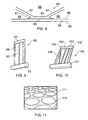
Figure 10 is a schematic front perspective view of a plurality of web formers as depicted inFigure 9 within a component structure; and -
Figure 11 illustrates a surface of a skin in accordance with the invention having key features to locate web formers. - As indicated above, prior component structures such as those used in blades have not fully utilised damping materials and media in the structure; so it is desirable to provide some flexibility in the structure. However, that flexibility must not be at the expense of achieving adequate blade definition and shaping for function. The invention provides flexibility through use of a web former which presents a skin of a structure using bond areas suspended upon a membrane. Thus, in comparison with prior girder structures, the presentation and support of the skin forming the blade structure is discontiguous and suspended on the membrane.
- The web former can be made from any appropriate material, and comprises a single layer or multiple layers, normally of perforated metallic or non-metallic web. Generally, the web former is secured to at least one skin through diffusion bonding, or possibly by an appropriate adhesive.
-
Figure 2 provides a front perspective view of a first configuration of ablade structure 30, in accordance with of the invention. It will be appreciated that normally a skin or layer will be provided either side of a web former 31. InFigure 2 , only alower skin 32 is depicted for clarity, the upper skin being removed. The web former 31 is therefore secured upon thelower skin 32 throughbond areas 33. It will be appreciated thatalternate bond areas 34 would be associated with the upper layer or skin (not shown). - The web former 31 has
membrane sections 35 which angularly extend between thebond areas bond areas web membranes 35, extending between them. In such circumstances, thebond areas membranes 35, and therefore it will be appreciated that the web former 31 - through appropriate shaping in terms of depth, angle and size of membranes 35 - along withbond areas skins 32 or layers as required. - Normally, at least one of the
bond areas skin 32; whilst the other skin may simply be offset by abutment of a bond pad with the skins to provide even greater flexibility in the structural parts of theblade structure 30, and to utilise the damping capabilities of the damping material located about and embedding theweb former 31. - As illustrated in
Figure 2 , ablade structure 30 can be created by a single web former extending betweenopposed skins 32. Such astructure 30 may be weak, particularly in the interstices betweenbond areas structure 30. In such circumstances, as depicted inFigure 3 , a webformer combination 40 can comprise interengaging orlocking web formers bond areas bond areas 43 extend intogaps 45 inweb 41 whilstbond areas 44 extend intogaps 46 in web former 42. As previously, the membranes of therespective web formers respective bond areas gaps bond areas bond areas 43 of oneweb 42 may be secured to the skin on one side and simply abut to support the skin on the other side of the bond structure which is secured to theother bond areas 44 of theother web former 41. In this way, the structure 40 - when secured to skins either side - provides a highly flexible but nevertheless robust presentation of the blade structure. The flexibility allows embedded damping material about theweb formers - It will be appreciated that the robustness of presentation and shaping of the bond structure in accordance with the invention depends, as indicated, upon the dimensions and angles of the membranes extending between bond areas. There will be a limit to the capabilities of such configurations. Thus, to achieve appropriate or desired shaping, as depicted in
Figure 4 , stacks of web formers in accordance with the invention may be utilised. In such circumstances a webformer structure 50 comprises a lower web former 51 and an upper web former 52 with membranes andrespective bond areas bond areas web formers Other bond areas respective formers - As indicated above, generally the web formers will be surrounded or embedded in a damping material. Thus, as the structure flexes the membranes will similarly flex to allow the damping material to absorb vibrations and acoustic noise. It is also possible to provide - either between the bonding areas in engagement with the skin, or between bonding areas engaging each other in stacks or web formers as depicted in
Figure 4 - a layer of dampingmaterial 55. As depicted inFigure 5 , a general configuration of the blade structure is similar to that depicted inFigure 3 , with interlockingweb formers bonding areas layer 155 between thebonding areas areas layer 155 will itself provide some flexibility for absorption of vibration etc. - As indicated above, web formers in accordance with the invention are generally secured at least to one skin defining the shape for the blade structure. Thus, as depicted in
Figure 6 , web formers can act as effective reinforcers - secured to one side of a skin but without interaction with a similar web former secured to the other side of the skin. In such circumstances, there is agap 65 betweenweb formers -
Figure 7 provides a further illustration of a blade structure incorporating interlockingweb formers structure 70. Again theweb formers respective bond areas 73, 74 appropriately positioned to enable at least support for a skin or to be bonded to that skin to define the blade structure in use. Between the interstices of theweb formers 71, 72 a volume of visco-elastic damping material is located inareas 75, such that deformation of theweb formers - It will be appreciated that the invention depends upon the bonding areas providing anchors or support positions for the skin of the blade structure. Particularly where the bond areas are secured to the skin, care must be taken that the flexing of the associated web membranes does not overly stress the skin or the membrane itself. In such circumstances, as depicted in
Figure 8 , at abond site 85 for abond area 83 to askin 84 of astructure 80 in accordance with the invention it will be noted that aradial feature 81 is provided. Thisradial feature 81 reduces stress concentration at a junction between thebond area 83 and aninner surface 86 of theskin 84, as well as withmembranes 87 extending away from thebond area 83. As indicated previously, through the provision of a web former comprising themembranes 87 andbond areas 83, presentation of theskin 84 is effectively suspended. In such circumstances, impacts upon anexternal surface 88 of theskin 84 can be absorbed by themembranes 87. It will also be understood that generally themembranes 87, as part of a web former in accordance with the invention, will be surrounded and embedded inareas 89 with a damping material to further enhance absorption of vibrations. It is by combining the suspension with themembranes 87 with the damping material that a good, consistent and robust component structure shape can be achieved, without the necessity of a rigid girder construction as with previous blade structures. - An alternative form of web former in accordance with the invention is to use an undulating strip or ribbon as depicted in
Figure 9. Figure 9 schematically illustrates ablade structure 90 extending from aroot 91. Only one undulating strip orribbon 92 is shown extending from aroot 91 end of thestructure 90 to atip end 93 in a space between askin 94 and another skin (not shown) but usually there will be a number of undulating strips. Between theskin 94 and the other skin (not shown) a cavity is provided, supported and presented by the undulating strip orribbon 92. Generally bends or folds in the strip orribbon 92 are diffusion bonded to theskin 94 or other internal panels. Thus, once formed, the strip orribbon 92 supports the blade structure with effective membranes between the bonded areas diffusion bonded to the respective skin or internal panels of thestructure 90. - Typically, in order to provide appropriate support over the full width and length of a blade structure it will be appreciated that a plurality of undulating strips or ribbons will be provided. Thus, as illustrated in
Figure 10 , ablade structure 100 is shown extending from aroot 101 with a cavity between askin 104 and another skin (not shown).Ribbons 102 extend between theroot 101 and atip portion 103 and are generally parallel. However, it will be understood that the undulating strips of ribbons are provided for appropriate support within thestructure 100 and therefore can be presented asymmetrical and non parallel to each other as depicted with regard to undulatingstrip 106. - The choice and position of the undulating
strips blade structure - In accordance with the invention, by positioning of the bonding areas along with the membranes between them, in terms of width, orientation and angle, adequacy of reinforcement whilst maintaining flexibility for use in combination with a damping material is achieved. The bond areas are effectively suspended upon the membranes between for flexibility. The distribution of the bond areas will be chosen dependent upon expected impact levels and other factors with regard to the component structure.
- As indicated, the positioning in the bond areas and their retention is important within a blade structure in accordance with the invention. There will be flexibility about the membranes between the bond areas, and therefore, as indicated above, radial bonding features 89 can be provided to avoid stressing. It will also be understood that a keyed association between skins or panels and the bonding area parts of the web may be provided. As depicted in
Figure 11 a tessellated textured surface is machined into an inner side of a panel or skin. The tessellated textured surface createswells 110 in the panel skin surface which adjust its flexibility but also provide locations for engaging bond areas.. - The area of the
wells 110 will generally be smaller than that of the bond areas. In a typical embodiment, the area of thewells 110 will be about one-fifth the area of the bond areas. - Component structures in accordance with the invention may be formed from ready machined and shaped elements secured together as appropriate.
- Alternatively, expansive plastic deformation techniques such as superplastic forming (SPF) can be utilised in order to create the blade structure. In this case, respective panels or skins of material will be presented with membrane former members in a flat state between them. The former members will be secured by appropriate techniques such as diffusion bonding or adhesive at the desired locations and the arrangement sealed about its edge. In such circumstances, once an expansive gas is presented between the skins or panels the arrangement will expand, with retention of the bonding at the bond areas, in order to create the web formers in accordance with the invention. The spacing and sizes of the bond areas, along with inflation pressure etc., will define the shape of the blade. The interconnecting membrane formers between the bond areas will then retain that component structure shape as required. In accordance with the invention, the shaped component structure will then be filled with a damping material. Alternatively, and possibly more conveniently, the damping material may be utilised as the means by which expansion of the component structure is achieved. In such circumstances, subsequent to the bonding process to secure the precursor web formers to the skins or panels and sealing as appropriate the damping material will be forcefully injected between the panels in order to create the structural shape in accordance with the invention. It will be understood that the elastic deformation process may be provided within a shaping mould to limit strain upon the bonding areas in engagement with the skin or panel.
- With regard to ribbon or strip web formers, the membranes between the bonding areas will be used in conjunction with a damping filler to achieve a desired structural shaping. These ribbons may be straight or curved or otherwise configured to provide the desired structure. The ribbons can have a regular repeat spacing or non-regular spacing of waves and undulations as required to support and present the structure. The ribbon membranes, in association with a damping filler, will carry some radial load and therefore prevent separation and de-bonding by the damping filler from association with inner surfaces of the blade structure, as well as interlock the damping material as a mechanical feature within the structure. Similarly, a mesh web former will act two dimensionally in order to carry some radial load and therefore prevent separation of the damping filler within the bond structure, as well as interlock the damping filler within the structure for better integration.
- By provision of a structure in accordance with the invention, it will be appreciated that the structure can flex in all directions by transmitting shear forces to the internal damping material. Prior blade structures, due to their more rigid girder reinforcement, tend not to flex evenly. By combining the benefits of a web former with a damper material, in accordance with the invention, improved overall performance is achieved without separation, as a result of the load being taken by the web former in combination with the damping filler. The damping medium is inhibited from separating from the structure subsequent to an impact or through normal operational stressing. The damping material is effectively mechanically keyed into the internal structure of the component and is therefore stabilised and bonded into that structure.
- It will be appreciated that damping materials in accordance with the invention as well as the use of the web former has little weight penalty compared with an existing structure incorporating robust girders for shaping.
- Although a component, and in particular a blade structure, has been utilised as an exemplary embodiment of a hollow structure in accordance with the invention, it will be appreciated that the combination of a web former and damper filler can also be utilised in other structures where greater flexibility for absorption, rather than absolute rigidity, will allow more efficient and effective operation. The invention may be utilised in any hollow structure which is internally supported and where there may be vibrations or impacts which could be beneficially dealt with by absorption rather than simply robustness. Some examples include within gas turbine engine fan blades, containment rings, outlet guide vanes and hollow static structures within the engine.
- Modifications and alterations to the embodiments of the invention as described above will be appreciated by those skilled in the art. Thus, for example, typically the web formers will be formed from the same metal or non-metallic material, but it may be desirable to provide different response or mechanical properties in different parts of the structure through the materials or thicknesses of materials or treatments of materials used at those parts.
- The skilled person would further recognise that instead of securing the web formers to the skins, at the bond areas using diffusion bonding or adhesive, as described above, they could equally well be secured using another suitable technique, such as brazing or welding.
- In the embodiments shown in
Figures 9 and 10 , the strips or ribbons, if arranged at an angle to one another, may be interwoven to create a more complex internal structure.
Claims (15)
- A component structure (30, 90) comprising a skin (32, 94) to define a shape as presented and secured on a web former (31, 92) having bond areas (33) suspended on a membrane, the skin flexibly presented upon the web former.
- A structure as claimed in claim 1, wherein the component structure is a blade.
- A structure as claimed in claim 1 or claim 2, and formed by superplastic forming.
- A structure as claimed in any preceding claim, wherein the web former comprises a mesh with the membrane angularly orientated to present respective bond areas laterally displaced from each other.
- A structure as claimed in any preceding claim, wherein the web former comprises a repeating tessellated pattern.
- A structure as claimed in any of claims 1 to 3, wherein the web former comprises a plurality of undulating strips or ribbons (92, 102, 106).
- A structure as claimed in claim 6 wherein the undulating strips or ribbons are substantially parallel to one another.
- A structure as claimed in any preceding claim, wherein there is a plurality of web formers (41, 42; 51, 52; 61, 62; 71, 72).
- A structure as claimed in claim 8, wherein the web formers interlock with each other (41, 42; 71, 72).
- A structure as claimed in any preceding claim, wherein the structure incorporates an intermediate layer (75).
- A structure as claimed in claim 10, wherein the web former is presented upon the intermediate layer.
- A structure as claimed in any preceding claim, wherein the web former is embedded and/or surrounded with a damping medium within the structure.
- A structure as claimed in any preceding claim, wherein the bond areas have a radial edge (81) to avoid stress concentration when secured to the skin.
- A structure as claimed in any preceding claim, wherein the skin (111) and/or web former incorporate key features (110) to interlock with each other.
- A gas turbine engine including a structure as claimed in any preceding claim.
Applications Claiming Priority (1)
| Application Number | Priority Date | Filing Date | Title |
|---|---|---|---|
| GBGB0808840.3A GB0808840D0 (en) | 2008-05-15 | 2008-05-15 | A compound structure |
Publications (2)
| Publication Number | Publication Date |
|---|---|
| EP2119871A2 true EP2119871A2 (en) | 2009-11-18 |
| EP2119871A3 EP2119871A3 (en) | 2017-08-16 |
Family
ID=39571415
Family Applications (1)
| Application Number | Title | Priority Date | Filing Date |
|---|---|---|---|
| EP09251303.5A Withdrawn EP2119871A3 (en) | 2008-05-15 | 2009-05-13 | A component structure |
Country Status (3)
| Country | Link |
|---|---|
| US (1) | US8241004B2 (en) |
| EP (1) | EP2119871A3 (en) |
| GB (1) | GB0808840D0 (en) |
Cited By (9)
| Publication number | Priority date | Publication date | Assignee | Title |
|---|---|---|---|---|
| EP2418353A3 (en) * | 2010-08-09 | 2014-01-15 | Rolls-Royce plc | An aerofoil, an aerofoil sub-assembly and a method of making the same |
| WO2014011290A2 (en) | 2012-04-24 | 2014-01-16 | United Technologies Corporation | Airfoil having internal lattice network |
| US8701286B2 (en) | 2010-06-02 | 2014-04-22 | Rolls-Royce Plc | Rotationally balancing a rotating part |
| US8857054B2 (en) | 2007-07-13 | 2014-10-14 | Rolls-Royce Plc | Method of forming an aerofoil with a damping filler |
| US8920893B2 (en) | 2009-01-27 | 2014-12-30 | Rolls-Royce Plc | Article with an internal structure |
| US8986490B2 (en) | 2010-11-26 | 2015-03-24 | Rolls-Royce Plc | Method of manufacturing a component |
| EP3260659A1 (en) * | 2016-06-22 | 2017-12-27 | United Technologies Corporation | Fan blade filler |
| EP3461994A1 (en) * | 2017-09-29 | 2019-04-03 | Rolls-Royce plc | Method for forming a blade or vane for a gas turbine engine |
| US10774653B2 (en) | 2018-12-11 | 2020-09-15 | Raytheon Technologies Corporation | Composite gas turbine engine component with lattice structure |
Families Citing this family (14)
| Publication number | Priority date | Publication date | Assignee | Title |
|---|---|---|---|---|
| GB0412915D0 (en) * | 2004-06-10 | 2004-07-14 | Rolls Royce Plc | Method of making and joining an aerofoil and root |
| GB2450935B (en) * | 2007-07-13 | 2009-06-03 | Rolls Royce Plc | Component with internal damping |
| GB0808840D0 (en) | 2008-05-15 | 2008-06-18 | Rolls Royce Plc | A compound structure |
| GB2462102B (en) * | 2008-07-24 | 2010-06-16 | Rolls Royce Plc | An aerofoil sub-assembly, an aerofoil and a method of making an aerofoil |
| GB0901318D0 (en) * | 2009-01-28 | 2009-03-11 | Rolls Royce Plc | A method of joining plates of material to form a structure |
| GB0904571D0 (en) * | 2009-03-18 | 2009-08-12 | Rolls Royce Plc | A method of manufacturing a component comprising an internal structure |
| GB0907004D0 (en) * | 2009-04-24 | 2009-06-03 | Rolls Royce Plc | A method of manufacturing a component comprising an internal structure |
| GB201001000D0 (en) * | 2010-01-22 | 2010-03-10 | Rolls Royce Plc | Method of forming a hollow component with an internal structure |
| JP5660883B2 (en) * | 2010-12-22 | 2015-01-28 | 三菱日立パワーシステムズ株式会社 | Steam turbine vane, steam turbine |
| EP3894664B1 (en) * | 2018-12-11 | 2023-07-26 | General Electric Company | Lattice structures for use in a damping system for a turbine blade, vibration damping system for a turbine blade and turbine blade |
| US11136889B2 (en) * | 2019-07-04 | 2021-10-05 | Doosan Heavy Industries & Construction Co., Ltd. | Compressor blade having organic vibration stiffener |
| US11814973B2 (en) * | 2022-01-04 | 2023-11-14 | General Electric Company | Methods and apparatus to provide damping of an airfoil |
| US11840941B2 (en) | 2022-02-16 | 2023-12-12 | General Electric Company | Engine component with cooling architecture |
| US12392245B2 (en) | 2023-03-23 | 2025-08-19 | General Electric Company | Turbine engine airfoil with a crush initiator |
Family Cites Families (126)
| Publication number | Priority date | Publication date | Assignee | Title |
|---|---|---|---|---|
| US2202014A (en) * | 1938-02-10 | 1940-05-28 | Lougheed Victor | Air propeller blade and material for making same |
| GB842937A (en) | 1957-09-03 | 1960-07-27 | George Mountford Adie | Improvements in and relating to materials for use in the construction of buildings |
| US3111747A (en) | 1959-06-30 | 1963-11-26 | Olin Mathieson | Hollow articles |
| US3630240A (en) | 1969-09-18 | 1971-12-28 | Essex International Inc | Winding and transfer apparatus for dynamoelectric machine stator coils |
| FR2112116B1 (en) | 1970-11-05 | 1973-08-10 | Commissariat Energie Atomique | |
| FR2330276A5 (en) | 1973-12-05 | 1977-05-27 | United Aircraft Corp | SHOCK ABSORBER FOR TURBINE BLADES |
| US3927817A (en) | 1974-10-03 | 1975-12-23 | Rockwell International Corp | Method for making metallic sandwich structures |
| US4304821A (en) | 1978-04-18 | 1981-12-08 | Mcdonnell Douglas Corporation | Method of fabricating metallic sandwich structure |
| US4217397A (en) | 1978-04-18 | 1980-08-12 | Mcdonnell Douglas Corporation | Metallic sandwich structure and method of fabrication |
| US4292375A (en) | 1979-05-30 | 1981-09-29 | The United States Of America As Represented By The Administrator Of The National Aeronautics And Space Administration | Superplastically formed diffusion bonded metallic structure |
| US4361262A (en) | 1980-06-12 | 1982-11-30 | Rockwell International Corporation | Method of making expanded sandwich structures |
| US4393987A (en) * | 1981-09-30 | 1983-07-19 | The Boeing Company | Superplastically formed structure and method of making |
| US4522860A (en) | 1983-01-10 | 1985-06-11 | Metalcore Limited | Material for reinforcing core in a structure |
| US4811890A (en) | 1983-05-07 | 1989-03-14 | Rockwell International Corporation | Method of eliminating core distortion in diffusion bonded and uperplastically formed structures |
| US4530197A (en) | 1983-06-29 | 1985-07-23 | Rockwell International Corporation | Thick core sandwich structures and method of fabrication thereof |
| US4594761A (en) | 1984-02-13 | 1986-06-17 | General Electric Company | Method of fabricating hollow composite airfoils |
| DE3405736A1 (en) | 1984-02-17 | 1985-08-22 | Ipa-Isorast International S.A., Panama | FORMWORK ELEMENT FOR THE SHEATH CONCRETE CONSTRUCTION AND WARM INSULATION PANEL |
| GB8428064D0 (en) | 1984-11-06 | 1984-12-12 | British Aerospace | Forming complex hollow sectioned members |
| DE3680161D1 (en) | 1985-07-22 | 1991-08-14 | Matsushita Electric Industrial Co Ltd | ELECTRIC WATER HEATER. |
| GB2193306A (en) | 1986-04-29 | 1988-02-03 | Kenneth Higham | Electric heating systems |
| GB8623552D0 (en) | 1986-10-01 | 1986-11-05 | Davies B G | Temperature control system |
| GB2202619A (en) | 1987-03-24 | 1988-09-28 | Kenneth Higham | Electric heating systems |
| GB2206685A (en) | 1987-07-07 | 1989-01-11 | Paul Lenworth Mantock | Closed circuit water electric heating unit |
| GB2211593B (en) | 1987-10-24 | 1992-06-10 | Alan Nelson Middleton | Central heating convector radiator, water filled, heated by an electric element and having a power input cycling mode |
| US4882823A (en) | 1988-01-27 | 1989-11-28 | Ontario Technologies Corp. | Superplastic forming diffusion bonding process |
| DE8809721U1 (en) | 1988-07-28 | 1988-09-29 | Kermi GmbH, 8350 Plattling | Connection set for radiators with electric heating element |
| GB8821222D0 (en) | 1988-09-09 | 1988-12-14 | British Aerospace | Double curvature structures by superplastic forming & diffusion bonding |
| GB2228069A (en) | 1989-01-04 | 1990-08-15 | Gledhill Water Storage | Control of the heat in a thermal store provided by a tank of water |
| FR2651869A1 (en) | 1989-09-14 | 1991-03-15 | Comparon Jean Daniel | ELECTRIC BOILER WITH CYCLONIC TURBULENCE. |
| US5405242A (en) | 1990-07-09 | 1995-04-11 | United Technologies Corporation | Cooled vane |
| EP0469221A1 (en) | 1990-07-31 | 1992-02-05 | Peter Hediger | Device for dissecting a workpiece |
| BR7002400U (en) | 1990-11-08 | 1992-07-07 | Jose Carlos Cella | CONSTRUCTIVE ARRANGEMENT FOR TRIAC IN SHOWERS OR PASSAGE HEATERS |
| GB2251063A (en) | 1990-12-20 | 1992-06-24 | John Anthony Page | Self contained liquid filled radiator |
| FR2672826B1 (en) | 1991-02-20 | 1995-04-21 | Snecma | PROCESS FOR MANUFACTURING A HOLLOW BLADE FOR A TURBOMACHINE. |
| US5253419A (en) | 1991-02-20 | 1993-10-19 | Societe Nationale D'etude Et De Construction De Moteurs D'aviation "S.N.E.C.M.A." | Method of manufacturing a hollow blade for a turboshaft engine |
| CA2072239C (en) | 1991-06-27 | 1999-12-14 | Dipak J. Shah | Error based zone controller |
| DE69211069T2 (en) | 1991-07-29 | 1996-10-02 | Rolls Royce & Ass | Compressed gas tank |
| US5240376A (en) | 1991-07-31 | 1993-08-31 | Mcdonnell Douglas Corporation | SPF/DB hollow core fan blade |
| JP2808500B2 (en) | 1991-08-23 | 1998-10-08 | 三菱重工業株式会社 | Gas turbine hollow fan blades |
| US5243758A (en) | 1991-12-09 | 1993-09-14 | General Electric Company | Design and processing method for manufacturing hollow airfoils (three-piece concept) |
| US5330092A (en) | 1991-12-17 | 1994-07-19 | The Boeing Company | Multiple density sandwich structures and method of fabrication |
| DE9201770U1 (en) | 1992-02-12 | 1992-04-16 | Buderus Heiztechnik GmbH, 6330 Wetzlar | Device for receiving coded time signals transmitted by radio |
| DE4226468A1 (en) | 1992-08-10 | 1994-02-17 | Haschkamp Ernestine | Circuit arrangement for electric heaters |
| EP0594885B1 (en) | 1992-10-29 | 2000-03-15 | Landis & Gyr Technology Innovation AG | Method for controlling a heating system and device for carrying out the method |
| EP0594886B1 (en) | 1992-10-29 | 2001-07-18 | Landis & Gyr Technology Innovation AG | Method and controlling a heating system and device for carrying out the method |
| US5469618A (en) | 1993-12-06 | 1995-11-28 | General Electric Company | Method for manufacturing hollow airfoils (two-piece concept) |
| FR2715883B1 (en) | 1994-02-10 | 1996-03-29 | Snecma | Process for obtaining a circular metal part reinforced with fibers. |
| FR2728062A1 (en) | 1994-12-09 | 1996-06-14 | Sgs Thomson Microelectronics | HEATING SYSTEM COMPRISING A CONTROL UNIT AND RADIATORS PROVIDED WITH PRESENCE DETECTION MEANS |
| US5570552A (en) | 1995-02-03 | 1996-11-05 | Nehring Alexander T | Universal wall forming system |
| GB9503622D0 (en) | 1995-02-23 | 1995-04-12 | Crampton Frederick A | Space heating apparatus |
| US5692881A (en) | 1995-06-08 | 1997-12-02 | United Technologies Corporation | Hollow metallic structure and method of manufacture |
| FR2739045B1 (en) | 1995-09-27 | 1997-10-31 | Snecma | PROCESS FOR MANUFACTURING A HOLLOW BLADE OF A TURBOMACHINE |
| GB2305720B (en) | 1995-09-29 | 2000-01-26 | Tristat Controls Ltd | Water filled radiator heater |
| WO1997027045A2 (en) | 1996-01-12 | 1997-07-31 | The Boeing Company | Metal sandwich structure with integral hardpoint |
| ATE230855T1 (en) | 1996-03-12 | 2003-01-15 | Tyco Electronics Corp | ELECTRICAL HEATING SYSTEMS |
| JPH1054204A (en) | 1996-05-20 | 1998-02-24 | General Electric Co <Ge> | Multi-component wing for gas turbine |
| US5723225A (en) | 1996-08-26 | 1998-03-03 | Mcdonnell Douglas Corporation | Superplastically formed, diffusion bonded multiple sheet panels with web doublers and method of manufacture |
| US5820348A (en) | 1996-09-17 | 1998-10-13 | Fricke; J. Robert | Damping system for vibrating members |
| US5881459A (en) | 1996-09-27 | 1999-03-16 | Mcdonnell Douglas Corporation | Pressure communication for superplastically formed, diffusion bonded panels and method of manufacture |
| US5941446A (en) | 1997-07-10 | 1999-08-24 | Mcdonnell Douglas Corporation | SPF/DB airfoil-shaped structure and method of fabrication thereof |
| CA2307471A1 (en) | 1997-10-27 | 1999-05-06 | Siemens Westinghouse Power Corporation | Method of bonding cast superalloys |
| US6039542A (en) | 1997-12-24 | 2000-03-21 | General Electric Company | Panel damped hybrid blade |
| US6138898A (en) | 1998-12-22 | 2000-10-31 | The Boeing Company | Corner gap weld pattern for SPF core packs |
| FR2788842B1 (en) | 1999-01-27 | 2001-06-01 | Micrel | WATER CIRCULATION HEATING CONTROL DEVICE |
| US6220518B1 (en) | 1999-05-13 | 2001-04-24 | Acutherm L.P. | Process and apparatus for individual adjustment of the temperature set points of a plurality of VAV devices |
| FR2798458B1 (en) | 1999-09-15 | 2001-12-14 | Delta Dore | CONTROL DEVICE FOR A HEAT TRANSFER FLUID CIRCULATION SYSTEM |
| DE19956444B4 (en) | 1999-11-24 | 2004-08-26 | Mtu Aero Engines Gmbh | Process for the production of a lightweight component in composite construction |
| FR2804278B1 (en) | 2000-01-25 | 2006-08-04 | G C Technology | SEMICONDUCTOR POLYMER TEMPERATURE LIMITER AND HEATING APPARATUS INCLUDING SUCH LIMITER |
| US6454536B1 (en) | 2000-02-09 | 2002-09-24 | General Electric Company | Adhesion enhancers to promote bonds of improved strength between elastomers metals in lightweight aircraft fan blades |
| GB2360236B (en) | 2000-03-18 | 2003-05-14 | Rolls Royce Plc | A method of manufacturing an article by diffusion bonding and superplastic forming |
| TW486734B (en) | 2000-04-20 | 2002-05-11 | Mks Instr Inc | Heater control system including satellite control units with integrated power supply and electronic temperature control |
| FR2809853B1 (en) | 2000-06-02 | 2002-07-26 | Delta Dore | HIGH FREQUENCY WIRELESS TRANSMISSION METHOD FOR A REMOTELY CONTROLLED HEATING CONTROL DEVICE |
| FR2809832B1 (en) | 2000-06-02 | 2003-06-06 | Delta Dore | METHOD FOR CONFIGURING A REMOTE CONTROL HEATING CONTROL DEVICE |
| JP4530495B2 (en) | 2000-07-03 | 2010-08-25 | 富士重工業株式会社 | Method for integrally forming superplastic materials |
| JP3852555B2 (en) | 2000-09-01 | 2006-11-29 | 三菱電機株式会社 | Thermal control device, spacecraft, and thermal control method |
| US6745085B2 (en) | 2000-12-15 | 2004-06-01 | Honeywell International Inc. | Fault-tolerant multi-node stage sequencer and method for energy systems |
| GB0100695D0 (en) | 2001-01-11 | 2001-02-21 | Rolls Royce Plc | a turbomachine blade |
| EP1275748A3 (en) * | 2001-07-13 | 2004-01-07 | ALSTOM (Switzerland) Ltd | High temperature resistant coating with locally embedded protrusions and its application process |
| FI20011863A7 (en) | 2001-09-21 | 2003-03-22 | Flaekt Woods Ab | Method and apparatus for wirelessly controlling air handling equipment |
| FR2832212B1 (en) | 2001-11-13 | 2005-07-22 | Henri Louis Russi | HEAT PUMP RADIATOR |
| US7441615B2 (en) | 2001-12-07 | 2008-10-28 | General Motors Corporation | Modular chassis with simplified body-attachment interface |
| BE1014570A4 (en) | 2002-01-11 | 2004-01-13 | Sonaca Sa | Method of manufacturing a structure and structure obtained fluted thereby. |
| US6699015B2 (en) | 2002-02-19 | 2004-03-02 | The Boeing Company | Blades having coolant channels lined with a shape memory alloy and an associated fabrication method |
| GB2387669B (en) | 2002-04-16 | 2006-04-26 | Honeywell Control Syst | Improvements in temperature control systems |
| EP1499525A1 (en) | 2002-04-29 | 2005-01-26 | Rolls-Royce Naval Marine, Inc. | Propeller |
| FR2839372B1 (en) | 2002-05-06 | 2005-01-07 | Martinez Thierry | ENERGY CONTROL AND MANAGEMENT SYSTEM |
| WO2004005831A1 (en) | 2002-07-09 | 2004-01-15 | Zexel Valeo Climate Control Corporation | Tube for heat exchanger |
| GB2391270B (en) | 2002-07-26 | 2006-03-08 | Rolls Royce Plc | Turbomachine blade |
| GB2393498A (en) | 2002-09-26 | 2004-03-31 | Cqi Ct Glow | Remote controller for a boiler |
| FR2849488B1 (en) | 2002-12-26 | 2005-02-25 | Renault Sa | SENSITIVELY RIGID TUBE FOR HIGH PRESSURE CIRCUIT |
| GB2397855B (en) | 2003-01-30 | 2006-04-05 | Rolls Royce Plc | A turbomachine aerofoil |
| DE10312373B3 (en) | 2003-03-20 | 2004-04-22 | Buderus Heiztechnik Gmbh | Operating method for room heating regulation has energy-saving operating mode combined with night-time operating phase initiated by time clock |
| DE10312668B3 (en) | 2003-03-21 | 2004-06-24 | Honeywell Ag Home And Building Control | Room temperature regulation system for centrally-heated building with verification of authorization of room device used for transmitting required room temperature values |
| GB2400055B (en) | 2003-03-29 | 2006-01-11 | Rolls Royce Plc | A hollow component with internal damping |
| FR2853572B1 (en) | 2003-04-10 | 2005-05-27 | Snecma Moteurs | METHOD FOR MANUFACTURING A HOLLOW MECHANICAL WELDING-DIFFUSION MECHANICAL PIECE AND SUPERPLASTIC FORMING |
| GB2401407A (en) | 2003-05-03 | 2004-11-10 | Rolls Royce Plc | a hollow component with internal vibration damping |
| CZ13445U1 (en) | 2003-05-14 | 2003-06-30 | Korado A. S. | Heating plate-like element for combined heating |
| GB2402716B (en) | 2003-06-10 | 2006-08-16 | Rolls Royce Plc | A damped aerofoil structure |
| KR100526824B1 (en) | 2003-06-23 | 2005-11-08 | 삼성전자주식회사 | Indoor environmental control system and method of controlling the same |
| PT1652408E (en) | 2003-07-30 | 2009-10-29 | Saint Gobain | Electric heating system |
| BE1015775A3 (en) | 2003-11-07 | 2005-08-02 | Defx S A | Radiator. |
| GB2408295A (en) | 2003-11-14 | 2005-05-25 | Rolls Royce Plc | An assembly with a plastic insert between two metal components |
| US7048175B2 (en) | 2003-12-19 | 2006-05-23 | The Boeing Company | Friction welded structural assembly and preform and method for same |
| US7775452B2 (en) | 2004-01-07 | 2010-08-17 | Carrier Corporation | Serial communicating HVAC system |
| US7744008B2 (en) | 2004-01-08 | 2010-06-29 | Robertshaw Controls Company | System and method for reducing energy consumption by controlling a water heater and HVAC system via a thermostat and thermostat for use therewith |
| US7377450B2 (en) | 2004-01-20 | 2008-05-27 | Carrier Corporation | Control of multi-zone and multi-stage HVAC system |
| US7125225B2 (en) | 2004-02-04 | 2006-10-24 | United Technologies Corporation | Cooled rotor blade with vibration damping device |
| GB2411462B (en) | 2004-02-25 | 2008-10-08 | Basic Holdings | Heating devices |
| US7090464B2 (en) | 2004-07-13 | 2006-08-15 | General Electric Company | Methods and apparatus for assembling rotatable machines |
| DE602005000542T2 (en) | 2004-09-29 | 2007-06-14 | Nissan Motor Co., Ltd., Yokohama | Preform, hydroforming and so produced product |
| US7180039B2 (en) | 2004-10-29 | 2007-02-20 | Osram Sylvania Inc. | Heater with burnout protection |
| GB0424481D0 (en) * | 2004-11-05 | 2004-12-08 | Rolls Royce Plc | Composite aerofoil |
| US7247003B2 (en) * | 2004-12-02 | 2007-07-24 | Siemens Power Generation, Inc. | Stacked lamellate assembly |
| US7410342B2 (en) | 2005-05-05 | 2008-08-12 | Florida Turbine Technologies, Inc. | Airfoil support |
| DK1754886T3 (en) * | 2005-08-17 | 2012-12-17 | Gen Electric | Rotor blade for a wind turbine |
| US7334997B2 (en) | 2005-09-16 | 2008-02-26 | General Electric Company | Hybrid blisk |
| US20070243408A1 (en) | 2005-11-22 | 2007-10-18 | Straza George C P | Formed core sandwich structure and method and system for making same |
| GB0601220D0 (en) | 2006-01-21 | 2006-03-01 | Rolls Royce Plc | Aerofoils for gas turbine engines |
| GB2450934B (en) | 2007-07-13 | 2009-10-07 | Rolls Royce Plc | A Component with a damping filler |
| GB2450935B (en) | 2007-07-13 | 2009-06-03 | Rolls Royce Plc | Component with internal damping |
| GB2450936B (en) | 2007-07-13 | 2010-01-20 | Rolls Royce Plc | Bladed rotor balancing |
| US7875537B2 (en) | 2007-08-29 | 2011-01-25 | Cree, Inc. | High temperature ion implantation of nitride based HEMTs |
| GB0808840D0 (en) | 2008-05-15 | 2008-06-18 | Rolls Royce Plc | A compound structure |
| GB2462102B (en) | 2008-07-24 | 2010-06-16 | Rolls Royce Plc | An aerofoil sub-assembly, an aerofoil and a method of making an aerofoil |
| GB0901318D0 (en) | 2009-01-28 | 2009-03-11 | Rolls Royce Plc | A method of joining plates of material to form a structure |
| GB0903280D0 (en) | 2009-02-27 | 2009-04-08 | Rolls Royce Plc | Method of manufacturing a blade |
-
2008
- 2008-05-15 GB GBGB0808840.3A patent/GB0808840D0/en not_active Ceased
-
2009
- 2009-05-11 US US12/453,435 patent/US8241004B2/en not_active Expired - Fee Related
- 2009-05-13 EP EP09251303.5A patent/EP2119871A3/en not_active Withdrawn
Cited By (12)
| Publication number | Priority date | Publication date | Assignee | Title |
|---|---|---|---|---|
| US8857054B2 (en) | 2007-07-13 | 2014-10-14 | Rolls-Royce Plc | Method of forming an aerofoil with a damping filler |
| US8920893B2 (en) | 2009-01-27 | 2014-12-30 | Rolls-Royce Plc | Article with an internal structure |
| US8701286B2 (en) | 2010-06-02 | 2014-04-22 | Rolls-Royce Plc | Rotationally balancing a rotating part |
| EP2418353A3 (en) * | 2010-08-09 | 2014-01-15 | Rolls-Royce plc | An aerofoil, an aerofoil sub-assembly and a method of making the same |
| US8986490B2 (en) | 2010-11-26 | 2015-03-24 | Rolls-Royce Plc | Method of manufacturing a component |
| WO2014011290A2 (en) | 2012-04-24 | 2014-01-16 | United Technologies Corporation | Airfoil having internal lattice network |
| EP2841706A4 (en) * | 2012-04-24 | 2015-08-19 | United Technologies Corp | CARRIER SURFACE WITH INTERNAL TRELLIS NETWORK |
| US9470095B2 (en) | 2012-04-24 | 2016-10-18 | United Technologies Corporation | Airfoil having internal lattice network |
| EP3260659A1 (en) * | 2016-06-22 | 2017-12-27 | United Technologies Corporation | Fan blade filler |
| EP3461994A1 (en) * | 2017-09-29 | 2019-04-03 | Rolls-Royce plc | Method for forming a blade or vane for a gas turbine engine |
| US10774653B2 (en) | 2018-12-11 | 2020-09-15 | Raytheon Technologies Corporation | Composite gas turbine engine component with lattice structure |
| US11168568B2 (en) | 2018-12-11 | 2021-11-09 | Raytheon Technologies Corporation | Composite gas turbine engine component with lattice |
Also Published As
| Publication number | Publication date |
|---|---|
| GB0808840D0 (en) | 2008-06-18 |
| EP2119871A3 (en) | 2017-08-16 |
| US8241004B2 (en) | 2012-08-14 |
| US20090304517A1 (en) | 2009-12-10 |
Similar Documents
| Publication | Publication Date | Title |
|---|---|---|
| US8241004B2 (en) | Component structure | |
| EP2539602B1 (en) | Vibration damping structures and corresponding manufacturing method | |
| EP2096269B1 (en) | Fan track liner assembly for a gas turbine engine | |
| US9028219B2 (en) | Turbomachine blade | |
| EP1980714B1 (en) | Rotor blade and corresponding turbine | |
| US9494206B2 (en) | Vibration damping | |
| EP1621752B1 (en) | Noise absorbing liner assembly for a fan case | |
| US8715809B2 (en) | Composite structure | |
| US3883267A (en) | Blades made of composite fibrous material, for fluid dynamic machines | |
| CN101333943B (en) | Turbomachine stator damper device | |
| EP1876324A2 (en) | Gas turbine blade | |
| EP3318402A1 (en) | Energy absorbing beam and sandwich panel structure | |
| US20100212998A1 (en) | Cellular-core structure for an acoustic panel | |
| US7766625B2 (en) | Methods and apparatus for reducing stress in turbine buckets | |
| US20100054942A1 (en) | Blade assembly | |
| US11565496B2 (en) | Structural panel with woven element core | |
| EP2305953B1 (en) | Hollow turbine blade | |
| RU2382911C1 (en) | Fan hollow blade | |
| US20080019838A1 (en) | Blades | |
| EP1657402B1 (en) | Blade | |
| JP6138575B2 (en) | Axial turbomachinery rotor blades | |
| EP2418353B1 (en) | An aerofoil, an aerofoil sub-assembly and a method of making the same | |
| EP2305961A2 (en) | Impactor containment | |
| CN112460075B (en) | Composite adjustable stator blade | |
| EP3461994A1 (en) | Method for forming a blade or vane for a gas turbine engine |
Legal Events
| Date | Code | Title | Description |
|---|---|---|---|
| PUAI | Public reference made under article 153(3) epc to a published international application that has entered the european phase |
Free format text: ORIGINAL CODE: 0009012 |
|
| AK | Designated contracting states |
Kind code of ref document: A2 Designated state(s): AT BE BG CH CY CZ DE DK EE ES FI FR GB GR HR HU IE IS IT LI LT LU LV MC MK MT NL NO PL PT RO SE SI SK TR |
|
| RAP1 | Party data changed (applicant data changed or rights of an application transferred) |
Owner name: ROLLS-ROYCE PLC |
|
| PUAL | Search report despatched |
Free format text: ORIGINAL CODE: 0009013 |
|
| AK | Designated contracting states |
Kind code of ref document: A3 Designated state(s): AT BE BG CH CY CZ DE DK EE ES FI FR GB GR HR HU IE IS IT LI LT LU LV MC MK MT NL NO PL PT RO SE SI SK TR |
|
| AX | Request for extension of the european patent |
Extension state: AL BA RS |
|
| RIC1 | Information provided on ipc code assigned before grant |
Ipc: F01D 5/14 20060101AFI20170712BHEP Ipc: F01D 5/16 20060101ALI20170712BHEP Ipc: F01D 5/28 20060101ALI20170712BHEP |
|
| STAA | Information on the status of an ep patent application or granted ep patent |
Free format text: STATUS: THE APPLICATION IS DEEMED TO BE WITHDRAWN |
|
| 18D | Application deemed to be withdrawn |
Effective date: 20180217 |