EP2119627A1 - Noise reduction device - Google Patents
Noise reduction device Download PDFInfo
- Publication number
- EP2119627A1 EP2119627A1 EP08860879A EP08860879A EP2119627A1 EP 2119627 A1 EP2119627 A1 EP 2119627A1 EP 08860879 A EP08860879 A EP 08860879A EP 08860879 A EP08860879 A EP 08860879A EP 2119627 A1 EP2119627 A1 EP 2119627A1
- Authority
- EP
- European Patent Office
- Prior art keywords
- noise
- speaker
- seat
- reduction device
- noise reduction
- Prior art date
- Legal status (The legal status is an assumption and is not a legal conclusion. Google has not performed a legal analysis and makes no representation as to the accuracy of the status listed.)
- Granted
Links
- 230000009467 reduction Effects 0.000 title claims abstract description 70
- 230000005236 sound signal Effects 0.000 claims description 7
- 230000006870 function Effects 0.000 description 13
- 238000000034 method Methods 0.000 description 12
- 238000009434 installation Methods 0.000 description 11
- 239000000463 material Substances 0.000 description 9
- 230000001965 increasing effect Effects 0.000 description 8
- 230000000694 effects Effects 0.000 description 7
- 230000001603 reducing effect Effects 0.000 description 7
- 238000001514 detection method Methods 0.000 description 5
- 230000008859 change Effects 0.000 description 4
- 238000013461 design Methods 0.000 description 4
- 238000005192 partition Methods 0.000 description 4
- 238000007796 conventional method Methods 0.000 description 3
- 238000012545 processing Methods 0.000 description 3
- 230000007480 spreading Effects 0.000 description 3
- 238000003491 array Methods 0.000 description 2
- 238000010586 diagram Methods 0.000 description 2
- 210000005069 ears Anatomy 0.000 description 2
- 230000002708 enhancing effect Effects 0.000 description 2
- 230000007246 mechanism Effects 0.000 description 2
- 230000003340 mental effect Effects 0.000 description 2
- 238000004378 air conditioning Methods 0.000 description 1
- 238000006243 chemical reaction Methods 0.000 description 1
- 238000004891 communication Methods 0.000 description 1
- 239000012141 concentrate Substances 0.000 description 1
- 230000010485 coping Effects 0.000 description 1
- 230000003111 delayed effect Effects 0.000 description 1
- 238000002592 echocardiography Methods 0.000 description 1
- 230000008030 elimination Effects 0.000 description 1
- 238000003379 elimination reaction Methods 0.000 description 1
- 239000000446 fuel Substances 0.000 description 1
- 238000009413 insulation Methods 0.000 description 1
- 239000012774 insulation material Substances 0.000 description 1
- 230000010355 oscillation Effects 0.000 description 1
- 230000000644 propagated effect Effects 0.000 description 1
- 230000004044 response Effects 0.000 description 1
Images


Classifications
-
- B—PERFORMING OPERATIONS; TRANSPORTING
- B64—AIRCRAFT; AVIATION; COSMONAUTICS
- B64C—AEROPLANES; HELICOPTERS
- B64C1/00—Fuselages; Constructional features common to fuselages, wings, stabilising surfaces or the like
- B64C1/40—Sound or heat insulation, e.g. using insulation blankets
-
- B—PERFORMING OPERATIONS; TRANSPORTING
- B60—VEHICLES IN GENERAL
- B60R—VEHICLES, VEHICLE FITTINGS, OR VEHICLE PARTS, NOT OTHERWISE PROVIDED FOR
- B60R13/00—Elements for body-finishing, identifying, or decorating; Arrangements or adaptations for advertising purposes
- B60R13/08—Insulating elements, e.g. for sound insulation
- B60R13/0815—Acoustic or thermal insulation of passenger compartments
-
- G—PHYSICS
- G10—MUSICAL INSTRUMENTS; ACOUSTICS
- G10K—SOUND-PRODUCING DEVICES; METHODS OR DEVICES FOR PROTECTING AGAINST, OR FOR DAMPING, NOISE OR OTHER ACOUSTIC WAVES IN GENERAL; ACOUSTICS NOT OTHERWISE PROVIDED FOR
- G10K11/00—Methods or devices for transmitting, conducting or directing sound in general; Methods or devices for protecting against, or for damping, noise or other acoustic waves in general
- G10K11/16—Methods or devices for protecting against, or for damping, noise or other acoustic waves in general
- G10K11/175—Methods or devices for protecting against, or for damping, noise or other acoustic waves in general using interference effects; Masking sound
- G10K11/178—Methods or devices for protecting against, or for damping, noise or other acoustic waves in general using interference effects; Masking sound by electro-acoustically regenerating the original acoustic waves in anti-phase
- G10K11/1785—Methods, e.g. algorithms; Devices
- G10K11/17853—Methods, e.g. algorithms; Devices of the filter
-
- G—PHYSICS
- G10—MUSICAL INSTRUMENTS; ACOUSTICS
- G10K—SOUND-PRODUCING DEVICES; METHODS OR DEVICES FOR PROTECTING AGAINST, OR FOR DAMPING, NOISE OR OTHER ACOUSTIC WAVES IN GENERAL; ACOUSTICS NOT OTHERWISE PROVIDED FOR
- G10K11/00—Methods or devices for transmitting, conducting or directing sound in general; Methods or devices for protecting against, or for damping, noise or other acoustic waves in general
- G10K11/16—Methods or devices for protecting against, or for damping, noise or other acoustic waves in general
- G10K11/175—Methods or devices for protecting against, or for damping, noise or other acoustic waves in general using interference effects; Masking sound
- G10K11/178—Methods or devices for protecting against, or for damping, noise or other acoustic waves in general using interference effects; Masking sound by electro-acoustically regenerating the original acoustic waves in anti-phase
- G10K11/1785—Methods, e.g. algorithms; Devices
- G10K11/17857—Geometric disposition, e.g. placement of microphones
-
- G—PHYSICS
- G10—MUSICAL INSTRUMENTS; ACOUSTICS
- G10K—SOUND-PRODUCING DEVICES; METHODS OR DEVICES FOR PROTECTING AGAINST, OR FOR DAMPING, NOISE OR OTHER ACOUSTIC WAVES IN GENERAL; ACOUSTICS NOT OTHERWISE PROVIDED FOR
- G10K11/00—Methods or devices for transmitting, conducting or directing sound in general; Methods or devices for protecting against, or for damping, noise or other acoustic waves in general
- G10K11/16—Methods or devices for protecting against, or for damping, noise or other acoustic waves in general
- G10K11/175—Methods or devices for protecting against, or for damping, noise or other acoustic waves in general using interference effects; Masking sound
- G10K11/178—Methods or devices for protecting against, or for damping, noise or other acoustic waves in general using interference effects; Masking sound by electro-acoustically regenerating the original acoustic waves in anti-phase
- G10K11/1785—Methods, e.g. algorithms; Devices
- G10K11/17861—Methods, e.g. algorithms; Devices using additional means for damping sound, e.g. using sound absorbing panels
-
- G—PHYSICS
- G10—MUSICAL INSTRUMENTS; ACOUSTICS
- G10K—SOUND-PRODUCING DEVICES; METHODS OR DEVICES FOR PROTECTING AGAINST, OR FOR DAMPING, NOISE OR OTHER ACOUSTIC WAVES IN GENERAL; ACOUSTICS NOT OTHERWISE PROVIDED FOR
- G10K11/00—Methods or devices for transmitting, conducting or directing sound in general; Methods or devices for protecting against, or for damping, noise or other acoustic waves in general
- G10K11/16—Methods or devices for protecting against, or for damping, noise or other acoustic waves in general
- G10K11/175—Methods or devices for protecting against, or for damping, noise or other acoustic waves in general using interference effects; Masking sound
- G10K11/178—Methods or devices for protecting against, or for damping, noise or other acoustic waves in general using interference effects; Masking sound by electro-acoustically regenerating the original acoustic waves in anti-phase
- G10K11/1787—General system configurations
- G10K11/17879—General system configurations using both a reference signal and an error signal
- G10K11/17883—General system configurations using both a reference signal and an error signal the reference signal being derived from a machine operating condition, e.g. engine RPM or vehicle speed
-
- G—PHYSICS
- G10—MUSICAL INSTRUMENTS; ACOUSTICS
- G10K—SOUND-PRODUCING DEVICES; METHODS OR DEVICES FOR PROTECTING AGAINST, OR FOR DAMPING, NOISE OR OTHER ACOUSTIC WAVES IN GENERAL; ACOUSTICS NOT OTHERWISE PROVIDED FOR
- G10K2210/00—Details of active noise control [ANC] covered by G10K11/178 but not provided for in any of its subgroups
- G10K2210/10—Applications
- G10K2210/128—Vehicles
- G10K2210/1281—Aircraft, e.g. spacecraft, airplane or helicopter
-
- G—PHYSICS
- G10—MUSICAL INSTRUMENTS; ACOUSTICS
- G10K—SOUND-PRODUCING DEVICES; METHODS OR DEVICES FOR PROTECTING AGAINST, OR FOR DAMPING, NOISE OR OTHER ACOUSTIC WAVES IN GENERAL; ACOUSTICS NOT OTHERWISE PROVIDED FOR
- G10K2210/00—Details of active noise control [ANC] covered by G10K11/178 but not provided for in any of its subgroups
- G10K2210/30—Means
- G10K2210/321—Physical
- G10K2210/3221—Headrests, seats or the like, for personal ANC systems
-
- Y—GENERAL TAGGING OF NEW TECHNOLOGICAL DEVELOPMENTS; GENERAL TAGGING OF CROSS-SECTIONAL TECHNOLOGIES SPANNING OVER SEVERAL SECTIONS OF THE IPC; TECHNICAL SUBJECTS COVERED BY FORMER USPC CROSS-REFERENCE ART COLLECTIONS [XRACs] AND DIGESTS
- Y02—TECHNOLOGIES OR APPLICATIONS FOR MITIGATION OR ADAPTATION AGAINST CLIMATE CHANGE
- Y02T—CLIMATE CHANGE MITIGATION TECHNOLOGIES RELATED TO TRANSPORTATION
- Y02T50/00—Aeronautics or air transport
- Y02T50/40—Weight reduction
Definitions
- the present invention relates to a noise reduction device in a seat, and particularly, it relates to a noise reduction device to be used in a closed structure such as airplane and train.
- the place used In use of an inside space whose boundary is formed by a continuous wall as in an airplane or a train, the place used is a kind of closed structure, and if noise sources exist inside and outside the place used, it will cause a noise environment to be fixed for the users. As a result, although it depends upon the level of noise, the noise exerts physical and mental pressure upon the user, worsening the comfortability of the place used. Particularly, in the case of offering a service to the passengers in the cabin of an airplane, worsening of the comfortability will give serious hindrance to the quality of service operation.
- main noise sources include noise generated from machines such as propellers and engines for producing thrust forces of the airplane, and sound of air current generated as the airplane body moves in the air such as sound generated by end portions or both wings of the airplane flying through the air.
- inside noise makes the passengers feel uncomfortable and also causes hindrance to the voice service. Accordingly, the situation is strongly desired to be improved.
- a method using a passive attenuation means is commonly employed.
- a sound insulation material having acoustic absorptivity such as partition wall material or absorptive material is arranged between the closed structure and the noise generating source.
- a high-density partition wall material is used as partition wall material, and a sound absorbing sheet is used as absorptive material.
- a material having acoustic absorptivity is generally high-density, and such a high-density material increases in weight. As the weight increases, it causes the flying fuel to increase, and the flying distance to shorten. Accordingly, it results in worsening of the economy and function as an airplane.
- lowering of the strength such as being easy to be damaged and worsening of the design function such as quality of the touch cannot be ignored.
- an audio-erasing device comprising a microphone for detecting sound generated from noise sources, a controller which amplifies the electric signal input from the microphone and reverses the phase, and a speaker which converts the electric signal input from the controller to sound and transmits the sound.
- a method of executing measures for noise from the viewpoint of improving the comfortability at passenger seats which is based on a method of reducing noise by using the above-mentioned active attenuation means.
- those proposed include a method of disposing a noise reducing device in each seat and installing a speaker, microphone and controller in the vicinity of the seat, and a method of increasing the noise reducing effect for the user by disposing a plurality of speakers and microphones in the vicinity of the user at the seat.
- the speaker emitting the control sound for reducing noise must be disposed in a position close to the user's ear
- conventional method proposed is a method of correcting the positional relation between the user's ear and the speaker by changing the tilt angle and position of the speaker (e.g. refer to Patent documents 1, 2).
- adjustments of the acoustic device are studied in various ways, and for example, a method of correcting the positional relation between the user and the speaker by shifting the speaker position is disclosed (e.g. refer to Patent document 3).
- the device when the device is installed in a seat of an airplane or the like, it is required to reduce the size and weight of the seat and also to improve the reclining function for enhancing the using convenience, resulting in considerable change in posture of the user in the seat, and it makes the environment very severe for the installation of the noise reduction device at the seat.
- the regions where speakers can be arranged are limited, and therefore, a speaker held in a large cabinet cannot be installed. Accordingly, the speaker capacity is limited, and there arises a problem of sound quality such as frequency characteristics.
- the function is not enough to correct the speaker position with respect to posture change in the seat because of the difference in user's height and the reclining function, and there is a problem that it is difficult to realize effective reduction of noise at the user.
- the noise reduction device of the present invention comprises a noise detector for detecting noise generated from noise sources, a noise controller which produces control sound signal for eliminating the noise detected by the noise detector, and a control sound output unit for outputting a control sound based on the control sound signal from the noise controller, which is a noise reduction device disposed in a seat surrounded by a shell portion having a cavity, wherein the control sound output unit is built in the cavity of the shell portion.
- the cavity of the shell portion at the seat can be used as a cabinet for the control sound output unit (speaker), making it possible to increase the volume of the cabinet.
- the control sound output unit sound output unit
- a speaker having a larger cabinet is higher in capacity of reproducing low-frequency sound and less in reproduction delay of low-frequency sound, and it is possible to enhance the noise reduction effect in low frequency ranges.
- the holding strength of the control sound output unit can be enhanced. Further, comparing with such a case that the control sound output unit is built into the back of a chair in the seat, it brings about the following advantages.
- the volume of the cabinet can be increased, increasing the capacity of reproducing low-frequency sound and lessening the reproduction delay of low-frequency sound, and thereby, it is possible to enhance the noise reduction effect in low frequency ranges.
- the shell portion as compared with a chair is less in regulation of the airplane, and easier to install the control sound output unit. Thirdly, it can be installed irrespective of comfortability of the chair and can be individually changed in shape or specification, giving rise to increase of the design freedom.
- Fig. 1 is a plan view showing the installation environment of the noise reduction device in the preferred embodiment of the present invention.
- airplane 100 comprises engines 102a, 102b mounted in the right and left wings.
- engines 102a, 102b act upon each part of the airplane body as external noise sources NS1a, NS1b, for example, with respect to seat arrays 103a, 103b, 103c disposed in cabin A (e.g. first class), cabin B (e.g. business class), and cabin C (e.g.
- cabin A e.g. first class
- cabin B e.g. business class
- cabin C e.g.
- bumping sound air cutting noise generated by the air current bumping against the end portions or both wings of the airplane as the airplane body moves through the air at a high speed serves as noise source NS1c and gives bad influences to information services or the like in the airplane.
- Fig. 2 is a plan view showing the detail of installation environment of the noise reduction device, in which the arrangement of seats in cabin A and cabin B shown in Fig. 1 is partially enlarged.
- Cabin 100a is divided into cabin A and cabin B by using a wall, and seat arrays are disposed in cabin A and cabin B respectively.
- each seat array is furnished with hearing equipment and connected to system control device 104 provided with a switching device and data control server via communication lines 105a, 105b, 105c such as Internet (registered mark).
- noise sources NS1a, NSs1b generated from engines 102a, 102b and air cutting noise NS1c generated at end portions of the airplane body and in addition, noise sources NS2a to NS2e due to air conditioners or the like exist as internal noise sources.
- noise from noise source NS1a due to the engine mounted in the left wing ( Fig. 1 ) is strongest out of noises coming from noise sources NS1a to NS1c and noise sources NS2a to NS2e. Accordingly, in order to realize effective reduction of noise at each seat, out of noises emitted in various directions, it is necessary to take the measure mainly for noise that is strongest to the user sitting in the seat and gives bad influence to the sound environment of the seat.
- the seat has a shell structure surrounding the reclining portion from the back, and the shell is internally furnished with audio-video equipment such as television and radio to be used for enjoying movies or music, a working desk, power outlet for PC connection, etc.
- audio-video equipment such as television and radio
- the request for elimination of noise in the shell is especially very strong, and the material used for the shell itself has a sound insulation effect, but it is important to efficiently reduce noise existing around the shell or coming through the shell.
- Fig. 3A is a block diagram showing the basic configuration of the noise reduction device in the preferred embodiment of the present invention.
- Noise reduction device 300 comprises noise detector 320, noise controller 330, control sound generator 340, and error detector 350. The configuration and the function are described in the following.
- Noise detector 320 is disposed as a noise detecting unit for detecting noise emitted from noise source 310, which is a microphone (hereinafter referred to as microphone) having a function to detect noise information, convert it to electric signal, and output.
- noise source 310 which is a microphone (hereinafter referred to as microphone) having a function to detect noise information, convert it to electric signal, and output.
- Noise controller 330 as a noise control unit comprises A/D converter 331, 335, digital filter 332, filter renewing unit 333, and D/A converter 334, which produces control sound signal for controlling the control sound generator 340 in order to minimize the detection error in accordance with noise information from microphone 320 that is a noise detecting unit and error information from error detector 350.
- A/D converter 331 executes A/D conversion of noise signal from microphone 320 and outputs the signal to digital filter 332 and filter renewing unit 333.
- Digital filter 332 is formed of multi-stage taps, which is an FIR filter capable of freely setting the filter coefficient of each tap.
- the detection error information from error detector 350 in addition to the information from microphone 320 is inputted to filter renewing unit 333 via A/D converter 335, and each filter coefficient of digital filter 332 is adjusted so that the detection error is minimized. That is, control sound signal so as to become opposite in phase is superimposed on the noise from noise source 310 at the installation position of error detector 350, and it is outputted to the control sound generator via D/A converter 334.
- Control sound generator 340 is a speaker as control sound output unit, which is capable of converting the control sound signal received from D/A converter 334 to sound waves and emitting the output, having a function of emitting control sound that offsets the noise in the vicinity of ear 301b of user 301.
- Error detector 350 detects the sound after noise reduction as an error, and executes the feedback with respect to the operational result of noise reduction device 300. In this way, it is possible to minimize the noise at the ear position of the user at all times even when the noise environment changes.
- noise emitted from noise source 310 is detected by microphone 320, and the signal is processed by noise controller 330 to output a control sound from speaker 340, then the noise emitted from noise source 310 is combined with phase-reversed sound and transmitted to ear 301b of user 301, thereby reducing the noise.
- Fig. 3B illustrates a method of combining the control sound outputted from speaker 340 with the noise emitted from noise source 310.
- speaker 340 When the noise spreading angle is ⁇ with respect to main noise passage 310N that connects noise source 310 to ear 301b of user 301, speaker 340 is arranged within spreading angle ⁇ . In this way, the phase-reversed control sound emitted from speaker 340 is combined with the noise before reaching ear 301b of user 301. Also, since error microphone 350 is arranged as an error detector within the combining region, sound after noise reduction is detected as an error, and it is subjected to feedback with respect to the operational result of noise reduction device 300, and thereby, the noise reduction effect can be enhanced.
- noise reduction device 310 during the time until noise reaches control point (ear 301b) after being detected by microphone 320, it is necessary to reproduce control sound from speaker 340 by processing the signal in noise controller 330.
- the speaker is small in volume of the cabinet, response is delayed due to phase delay in low frequency range, and the control sound will not be reproduced in time, and sufficient noise reduction cannot be obtained in low frequency range.
- the cavity of the shell portion of the seat can be largely used as a cabinet of the speaker, and phase delay in low frequency range is lessened and processing time required for control sound reproduction is shortened, and it is possible to obtain sufficient noise reduction effect even in low frequency range.
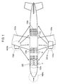
- Fig. 4A , B are a front view and a plan view showing an example of installing the noise reduction device in the preferred embodiment of the present invention in a seat of an airplane.
- Noise reduction device 400 is installed in seat 402, and seat 402 has a shell structure having a reclining function.
- Seat 402 comprises shell portion 402a and reclining portion 402b.
- Shell portion 402a holds reclining portion 402b as a base to secure the seat.
- reclining portion 402b comprises stool portion 402ba, back-rest 402b and head-rest 402bc.
- Stool portion 402ba, back-rest 402bb, and head-rest 402bc are engaged with each other, which are movably supported by shell portion 402a and capable of displaying a reclining function.
- Shell portion 402a is peripherally furnished with microphones 420a, 420b (corresponding to noise detector 320 of Fig.
- shell portion 402a is furnished with noise controller 430 (corresponding to noise controller 330 of Fig. 3A ) and speakers 440a to 440d (corresponding to control sound generator 340 of Fig. 3 ) at the back thereof, and speakers 440a, 440b are arranged at the back close to the ears of user 401, and speakers 440c, 440d are disposed at the either side opposing to the ears.
- noise controller 430 corresponding to noise controller 330 of Fig. 3A
- speakers 440a to 440d corresponding to control sound generator 340 of Fig. 3
- speakers 440a, 440b are arranged at the back close to the ears of user 401
- speakers 440c, 440d are disposed at the either side opposing to the ears.
- microphones 450a, 450b (corresponding to error detector 350 of Fig. 3A ) as error detectors are arranged between head 401a and speakers 440a to 440d respectively.
- Fig. 5 is a plan view showing the main configuration in the example of noise reduction device installed in a cabin of an airplane in the preferred embodiment of the present invention.
- noise reduction device 400 in the preferred embodiment of the present invention is installed in seat 502 arranged in cabin A ( Fig. 1 ) of an airplane.
- Seat 502 is disposed inside shell portion 502a surrounding the seat 502 in a shell-like fashion by its wall surface, maintaining the region occupied by the user, and comprises reclining portion (seat portion) 502b which is arranged in shell portion 502a and can be reclined.
- Shell portion 502a is provided with shelf portion 502aa opposing in the forward direction to reclining portion 502b and may display a function as a desk.
- reclining portion 502b comprises stool portion 502ba, back-rest 502bb, head-rest 502bc, and elbow-rest 502bd, 502be.
- stool portion 502ba is reclined forward, changing the tilt angle of back-rest 502bb engaging with stool portion 502ba, and head-rest 502bc can be mainly moved in the downward direction.
- noise sources such as engines mounted in the airplane body, air conditioners installed in the cabin, and the like.
- noise emitted from noise sources for example reaches the outer periphery of shell portion 502a mainly through main noise passage (noise route) NS51 to NS58 connecting each noise source to seat 502.
- main noise passage noise route
- NS51 to NS58 connecting each noise source to seat 502.
- microphones 520a to 5201 for example, there are provided at the outer periphery of shell portion 502a of seat 502, as a structural element of the noise reduction device in the preferred embodiment of the present invention, for example, there are provided microphones 520a to 5201 (corresponding to noise detector 320 of Fig. 3A ) for noise detection.
- shell portion 502a internally has a cavity at a position opposite to the back of reclining portion 502b, and speaker holder 503 as a speaker mounting member is disposed in the cavity.
- Speaker holder 503 is provided with speaker 540a and speaker 540b (corresponding to control sound generator 340 of Fig. 3A ) as control sound output unit in noise reduction device 400.
- Speaker in the present invention is a cone-shaped speaker as shown in Fig. 5 , which is formed with a voice coil around a permanent magnet and generates sound by applying an electric current to the voice coil to vibrate an oscillation plate. As a speaker, it is allowable to use the one without such a voice coil, and the shape is not limited to a cone-like shape.
- the low frequency characteristic is poor in use of only a speaker, it is usually housed in a box-like speaker holder which resonates the sound with the back of the speaker closed.
- the shell portion is greatly bulged at the back so that a large-volume speaker holder 503 can be formed.
- speaker holder 503 is arranged close to and nearly parallel to head-rest 502bc of reclining portion 502b and is movably configured.
- speaker 540a and speaker 540b can be arranged nearly at the height of the ear of user 501.
- FIG. 5 shows an example of disposing speakers 540a, 540b at either side of ear 501b in such a configuration that speaker holder 503 is formed like a flat plate and positioned near the back of ear 501b at head 501a of user 501. Speaker holder 503 is held by slide portion 504 having a screw feeding mechanism so that it is movable nearly up and down.
- shell portion 502a and speaker holder 503 of seat 502 can be used as the cabinet of speaker 540a and speaker 540b.
- the space can be increased for speakers 540a and 540b in a limited space.
- the cabinet volume can be enlarged, enhancing the low frequency reproduction capacity of speaker 540a and 540b and lessening the delay in low frequency reproduction, and it is possible to enhance the noise reduction effect in the low frequency range.
- the strength of the structure for holding speaker 540a and speaker 540b can be increased.
- the internal cavity of shell portion 502 is allowable to be formed over the entire periphery of shell portion 502 as well as at the back, and in this way, the volume of the cavity or the volume of the cabinet can be further increased, and it is possible to further improve the acoustic characteristic of control sound output.
- Fig. 6A to D are side views and partly sectional views showing main configuration of an application example of seat 602 in which noise reduction device 400 in the preferred embodiment of the present invention is installed.
- Fig. 6A is a side view related to seat 602, showing the positional relation between shell portion 602a and reclining portion 602b when the user is sitting in the standard posture (without reclining the seat) at seat 602 having a reclining function.
- Fig. 6B is a side view showing the positional relation when the seat is fully reclined.
- Fig. 6C is a sectional view in the direction of arrow A in Fig. 6A , showing an example related to the using environment of noise reduction device 400 with respect to user 601 sitting in seat 602.
- Fig. 6D shows another application example of the structure shown in Fig. 6C .
- seat 602 comprises shell portion 602a and reclining portion 602b as a base, and reclining portion 602b is movably held by shell portion 602a.
- Reclining portion 602b comprises stool portion 602ba, back-rest 602bb, and head-rest 602bc. Stool portion 602ba, back-rest 602bb, and head-rest 602bc are engaged with each other and movably held in shell portion 602a. Due to this configuration, seat 602 can be reclined by manipulating the operation lever (not shown).
- the back of seat 602 is covered with shell portion 602a, and the seat can be reclined by sliding the reclining portion 602b forward, and it is possible to keep constant the space occupied by each seat without giving influence to the space of the adjacent seat at the back in reclining operation.
- speaker holder 603 is disposed as a speaker mounting member at the back of reclining portion 602b, and speaker holder 603 is provided with speaker 640 (corresponding to control sound generator 340 of Fig. 3A ) as a control sound generator in noise reduction device 400. Also, speaker holder 603 is arranged close to and nearly parallel to head-rest 602bc of reclining portion 602b, which is configured so as to be movable, and also, speaker 640 can be disposed nearly at the ear height of user 601.
- Fig. 6B shows the positional relation between reclining portion 602b and shell portion 602a when the seat is reclined by the user and reclining portion 602b is tilted at the predetermined angle.
- stool portion 602ba is protruded forward of the seat
- back-rest 602bb is changed in tilt angle
- head-rest 602bc is lowered in height and moved to a lower position inside the shell portion 602a.
- speaker holder 603 moves in the direction B (nearly up and down) along with the vertical movement of head-rest 602bc, so that the positional relation between user's ear 601b and speaker 640 in the direction of height can be kept nearly constant.
- reclining portion 602b is tilted at the predetermined angle, but even in case of reclining to a full-flat state where the user's body is nearly horizontal, it can also be configured so that speaker 640 may follow the ear height of user 601.
- Fig. 6C shows an example of installing speakers 640a, 640b at either side of head-rest 602bc where speaker holder 603 is structurally plate-like and positioned close to the back of ear 601b at head 601a of user 601. Speaker holder 603 is movably held nearly in the vertical direction by slide portion 604 having a screw feeding mechanism or the like.
- Fig. 6D shows an example of installing speakers 640c, 640d at either side of ear 601b at head 601a of user 601 where speaker holder 603a is structurally nearly C-shaped.
- the speaker 640 is first adjusted to a position best for user 601 by the initial setting operation for using it, and then the standard position is set for speaker 640 in noise reduction device 400. After that, the amount of movement of head-rest 602bc interlocked with the reclining operation is detected by a sensor (not shown), and speaker holder 603 is moved in the same direction by the detected amount of movement, thereby adjusting the height of speaker 640.
- Speaker 640 can also be arranged not inside the shell portion 602 but inside the head-rest 602bc of reclining portion 602b. Also, in the case of a chair having no reclining function, the speaker can be disposed in the back portion of the chair. As in noise detection device 400 in the preferred embodiment, when speaker 640 is not housed in the chair (reclining portion) but in shell portion 602, it brings about the following advantages.
- the cabinet volume can be increased, and the processing speed of low frequency range becomes higher.
- shell portion 602 is less subjected to regulation (restriction) of an airplane as compared with a chair (reclining portion) and it is easier to install speaker 640.
- it can be installed irrespective of the sitting comfortability of chair (reclining portion) (when a large speaker is installed on a chair, it is necessary to change the design and the sitting comfortability is affected).
- the shape and specification can be changed independently of the chair (reclining portion), giving rise to the design freedom.
- the shell portion of the seat can be used as a cabinet for control sound output unit, and the cabinet volume can be increased in a limited space. Accordingly, it becomes possible to improve the acoustic characteristic of the control sound output and to realize efficient reduction of noise. Further, it is possible to strengthen the holding structure of the control sound output unit.
- the position of the control sound output unit can be corrected and optimized coping with difference in height of the user and change in posture at the seat due to reclining operation. Accordingly, noise reduction can be effectively realized for the user.
- speaker holder 603 moves nearly in the vertical direction along with the movement of head-rest 602bc, and the positional relation between ear 601b of the user and the height of speaker 640 is kept constant in the description.
- the movement of speaker holder 603 is not limited to the vertical direction.
- the reclining angle is constant or the user in the seat changes his or her facing direction, it is allowable to move the speaker holder in the forward, backward, right or left direction to follow the movement. In that case, it is allowable to automatically recognize the ear position by using an image sensor or the like and to move speaker holder 603 in accordance with the result of the recognition.
- engine is supposed to be main noise source, but noise source is not limited to this.
- noise source is not limited to this.
- noise of equipment for generating thrust of an airplane such propellers and engines in particular, complicatedly superimposed noise from many noise sources existing in the installation environment comes to the seat such as air cutting noise during flying, noise related to air current generated along with the movement of the airplane in the air, noise generated by air conditioning systems such as air conditioners, voice related to information service in the cabin, and indirect noise reflected from wall surfaces.
- the preferred embodiment of the present invention comprises error detector (error microphone) 350 for detecting control sound outputted from control sound generator (speaker) 340 in addition to noise detector (microphone) 320 as a noise detecting unit for detecting noise emitted from noise source 310, wherein the error of control sound can be corrected by detecting the synthetic sound of noise and control sound by means of error microphone 350.
- error microphone 350 is not an essential component element for the noise reduction device in the preferred embodiment of the present invention. Since error microphone 350 is usually disposed in the vicinity of the head of the user, the seat configuration near the user's head can be simplified by omitting error microphone 350. Accordingly, it is possible to realize a comfortable and low-cost noise reduction device which hardly gives mental pressure to the user.
- shell portion 502a is described as an oval structure ( Fig. 5 ) which surrounds reclining portion 502b from backward.
- any shape is allowable provided that the structure is able to partition the space between adjacent seats and has an opening for the user to get in and out of the seat.
- it is allowable to be rectangular or semi-circular to cover only the back portion.
- speaker holder 503 is arranged in the cavity of shell portion 502a ( Fig. 5 ) in the description.
- shell portion 502a depending upon the shape of shell portion 502a, it is sometimes difficult to obtain a cavity having a sufficient capacity or sometimes desirable to install the speaker holder in other place.
- Fig. 7 it is allowable to obtain a space for speaker holder 503a and 503b by partially expanding the outer periphery of the back of shell portion 502a.
- speaker 540a and speaker 540b can be respectively moved nearly in the vertical direction by slide portion 504a and slide portion 504b.
- the noise reduction device of the present invention is capable of providing a high-quality noise reduction device. Accordingly, the noise reduction device is effective to be used in spaces as in airplanes, trains, cars, etc. where noise is generated.
Landscapes
- Engineering & Computer Science (AREA)
- Physics & Mathematics (AREA)
- Acoustics & Sound (AREA)
- Multimedia (AREA)
- Mechanical Engineering (AREA)
- Aviation & Aerospace Engineering (AREA)
- Soundproofing, Sound Blocking, And Sound Damping (AREA)
- Fittings On The Vehicle Exterior For Carrying Loads, And Devices For Holding Or Mounting Articles (AREA)
- Chair Legs, Seat Parts, And Backrests (AREA)
- Seats For Vehicles (AREA)
Abstract
Description
- The present invention relates to a noise reduction device in a seat, and particularly, it relates to a noise reduction device to be used in a closed structure such as airplane and train.
- In airplanes and trains which generate considerable noise, when information is offered by voice service to the users, problems arise with noise generated at the seats.
- In use of an inside space whose boundary is formed by a continuous wall as in an airplane or a train, the place used is a kind of closed structure, and if noise sources exist inside and outside the place used, it will cause a noise environment to be fixed for the users. As a result, although it depends upon the level of noise, the noise exerts physical and mental pressure upon the user, worsening the comfortability of the place used. Particularly, in the case of offering a service to the passengers in the cabin of an airplane, worsening of the comfortability will give serious hindrance to the quality of service operation.
- Particularly, in the case of an airplane, main noise sources include noise generated from machines such as propellers and engines for producing thrust forces of the airplane, and sound of air current generated as the airplane body moves in the air such as sound generated by end portions or both wings of the airplane flying through the air. In this case, inside noise makes the passengers feel uncomfortable and also causes hindrance to the voice service. Accordingly, the situation is strongly desired to be improved.
- On the other hand, as a measure for reducing noise in a closed room, conventionally, a method using a passive attenuation means is commonly employed. In the conventional method, a sound insulation material having acoustic absorptivity such as partition wall material or absorptive material is arranged between the closed structure and the noise generating source. A high-density partition wall material is used as partition wall material, and a sound absorbing sheet is used as absorptive material. A material having acoustic absorptivity is generally high-density, and such a high-density material increases in weight. As the weight increases, it causes the flying fuel to increase, and the flying distance to shorten. Accordingly, it results in worsening of the economy and function as an airplane. Also, as a structural material, lowering of the strength such as being easy to be damaged and worsening of the design function such as quality of the touch cannot be ignored.
- In order to solve the problem involved in the measure for noise by using a passive attenuation means, as a method of reducing noise by using an active attenuation means, a conventional method of generating sound wave having a phase opposite to the phase of noise is generally executed. By using this method, it is possible to lower the noise level at the noise source or in the vicinity thereof in order to prevent the noise from being propagated to regions required to be reduced in noise. As a specific example, an audio-erasing device has been proposed, comprising a microphone for detecting sound generated from noise sources, a controller which amplifies the electric signal input from the microphone and reverses the phase, and a speaker which converts the electric signal input from the controller to sound and transmits the sound.
- Also, recently examined is a method of executing measures for noise from the viewpoint of improving the comfortability at passenger seats, which is based on a method of reducing noise by using the above-mentioned active attenuation means. For example, those proposed include a method of disposing a noise reducing device in each seat and installing a speaker, microphone and controller in the vicinity of the seat, and a method of increasing the noise reducing effect for the user by disposing a plurality of speakers and microphones in the vicinity of the user at the seat. In this case, it is necessary to take into account the positions of the speaker and microphone arranged with respect to the hearing conditions such as the user's posture, and the effect of noise reduction greatly depend upon the positions. Particularly, the speaker emitting the control sound for reducing noise must be disposed in a position close to the user's ear, and conventional method proposed is a method of correcting the positional relation between the user's ear and the speaker by changing the tilt angle and position of the speaker (e.g. refer to
Patent documents 1, 2). Regarding the speaker arrangement to the user, adjustments of the acoustic device are studied in various ways, and for example, a method of correcting the positional relation between the user and the speaker by shifting the speaker position is disclosed (e.g. refer to Patent document 3). - However, when the device is installed in a seat of an airplane or the like, it is required to reduce the size and weight of the seat and also to improve the reclining function for enhancing the using convenience, resulting in considerable change in posture of the user in the seat, and it makes the environment very severe for the installation of the noise reduction device at the seat. Particularly, in the method conventionally disclosed with respect to the arrangement of speakers at the seat, the regions where speakers can be arranged are limited, and therefore, a speaker held in a large cabinet cannot be installed. Accordingly, the speaker capacity is limited, and there arises a problem of sound quality such as frequency characteristics. Also, the function is not enough to correct the speaker position with respect to posture change in the seat because of the difference in user's height and the reclining function, and there is a problem that it is difficult to realize effective reduction of noise at the user.
-
Patent document 1 Unexamined Japanese Patent PublicationH10-143166 - Patent document 2 Unexamined Japanese Utility Model Publication
H5-50495 -
Patent document 3 Unexamined Japanese Patent Publication2006-166281 - The noise reduction device of the present invention comprises a noise detector for detecting noise generated from noise sources, a noise controller which produces control sound signal for eliminating the noise detected by the noise detector, and a control sound output unit for outputting a control sound based on the control sound signal from the noise controller, which is a noise reduction device disposed in a seat surrounded by a shell portion having a cavity, wherein the control sound output unit is built in the cavity of the shell portion.
- Due to such a configuration, the cavity of the shell portion at the seat can be used as a cabinet for the control sound output unit (speaker), making it possible to increase the volume of the cabinet. As is obvious to the person in charge of the work, a speaker having a larger cabinet is higher in capacity of reproducing low-frequency sound and less in reproduction delay of low-frequency sound, and it is possible to enhance the noise reduction effect in low frequency ranges. Also, the holding strength of the control sound output unit can be enhanced. Further, comparing with such a case that the control sound output unit is built into the back of a chair in the seat, it brings about the following advantages. Firstly, the volume of the cabinet can be increased, increasing the capacity of reproducing low-frequency sound and lessening the reproduction delay of low-frequency sound, and thereby, it is possible to enhance the noise reduction effect in low frequency ranges. Secondly, the shell portion as compared with a chair is less in regulation of the airplane, and easier to install the control sound output unit. Thirdly, it can be installed irrespective of comfortability of the chair and can be individually changed in shape or specification, giving rise to increase of the design freedom.
- Accordingly, it is possible to provide a noise reduction device which can be installed in the seat of an airplane or the like and assures excellent efficiency, quality, and comfortability.
-
-
Fig. 1 is a plan view showing the installation environment of a noise reduction device in the preferred embodiment of the present invention. -
Fig. 2 is a plan view showing the detail of installation environment of a noise reduction device in the preferred embodiment. -
Fig. 3A is a block diagram showing the basic configuration of a noise reduction device in the preferred embodiment. -
Fig. 3B shows a method of superimposing the noise emitted from a noise source on the control sound output from a speaker of the noise reduction device in the preferred embodiment. -
Fig. 4A is a front view showing an installation example of a noise reduction device in the preferred embodiment. -
Fig. 4B is a plan view showing an installation example of a noise reduction device in the preferred embodiment. -
Fig. 5 is a plan view showing an installation example of a noise reduction device in the preferred embodiment. -
Fig. 6A shows an application example of a noise reduction device in the preferred embodiment, which is a side view related to a seat showing the positional relation between shell portion and reclining portion when the user is in the standard posture (without reclining the seat) at the seat. -
Fig. 6B shows an application example of a noise reduction device in the preferred embodiment, which is a side view showing the positional relation when the reclining portion is fully shifted down. -
Fig. 6C is a sectional view along the arrow A inFig. 6A , showing an example related to the using environment of the noise reduction device with respect to the user sitting in the seat. -
Fig. 6D is another application example of the structure shown inFig. 6C . -
Fig. 7 is a plan view showing an installation example of a noise reduction device in the preferred embodiment. -
- 100
- Airplane
- 100a, A, B, C
- Cabin
- 101a, 101b
- Wing
- 102a, 102b
- Engine
- 103a, 103b, 103c
- Passenger seat array
- 104
- System control device
- 300, 400
- Noise reduction device
- 301,401,501,601
- User
- 301b, 501b, 601b
- Ear
- 310, NS1a, NS1b, NS1c, NS2a, NS2b
- Noise source
- 310N, 340N, NS51 to NS58
- Main noise passage (noise route)
- 320
- Noise detector (microphone)
- 330, 430
- Noise controller
- 331, 335
- A/D converter
- 332
- Digital filter
- 333
- Filter renewing unit
- 334
- D/A converter
- 340
- Control sound generator (speaker)
- 350
- Error detector (error microphone)
- 401a,501a,601a
- Head
- 402,502,602
- Seat
- 402a, 502a, 602a
- Shell portion
- 402b, 502b, 602b
- Reclining portion (seat portion)
- 420ba, 502ba, 602ba
- Stool portion
- 402bb, 502bb, 602bb
- Back-rest
- 402bc, 502bc, 602bc
- Head-rest
- 420a, 420b, 450a, 450b, 520a to 520l
- Microphone
- 440a, 440b, 440c, 440d, 540a, 540b,
- 640, 640a, 640b, 640c, 640d
- Speaker
- 502bd, 502be
- Elbow-rest
- 503, 503a, 503b, 603
- Speaker holder
- 504, 504a, 504b, 604
- Slide portion
- α
- Spreading angle
- The preferred embodiments of the present invention will be described in the following with reference to
Fig. 1 to Fig. 8 . - Regarding the noise reduction device in the preferred embodiment of the present invention, an example of installing the device in an airplane is described in the following.
- First, sound environment in an airplane required to be provided with a noise reduction device is described with reference to
Fig. 1 andFig. 2 . -
Fig. 1 is a plan view showing the installation environment of the noise reduction device in the preferred embodiment of the present invention. As shown inFig. 1 ,airplane 100 comprisesengines - From the viewpoint of sound environment of the airplane, not only rotating sound but also echoes due to air current are generated from the engine during flying. Therefore, the engine occupies an important position as a noise source. From the viewpoint of passenger services,
engines seat arrays -
Fig. 2 is a plan view showing the detail of installation environment of the noise reduction device, in which the arrangement of seats in cabin A and cabin B shown inFig. 1 is partially enlarged.Cabin 100a is divided into cabin A and cabin B by using a wall, and seat arrays are disposed in cabin A and cabin B respectively. Also, each seat array is furnished with hearing equipment and connected tosystem control device 104 provided with a switching device and data control server viacommunication lines cabin 100a, there exist external noise sources such as noise sources NS1a, NSs1b generated fromengines seat 105 disposed in cabin A, thenseat 105 is subjected to the influences of noise from noise sources NS1a to NS1c generated byengine 102a (Fig. 1 ) installed in the wing outside the window and caused due to air current noise, and noise sources NS2a to NS2e generated from air conditioners. For example, atseat 105 in cabin A, it can be predicted that noise from noise source NS1a due to the engine mounted in the left wing (Fig. 1 ) is strongest out of noises coming from noise sources NS1a to NS1c and noise sources NS2a to NS2e. Accordingly, in order to realize effective reduction of noise at each seat, out of noises emitted in various directions, it is necessary to take the measure mainly for noise that is strongest to the user sitting in the seat and gives bad influence to the sound environment of the seat. - Particularly, in the first class shown by cabin A in
Fig. 1 , the seat has a shell structure surrounding the reclining portion from the back, and the shell is internally furnished with audio-video equipment such as television and radio to be used for enjoying movies or music, a working desk, power outlet for PC connection, etc. Thus, it is strongly required for providing such an environment that the user is able to relax in the seat or concentrate on business work. Therefore, the request for elimination of noise in the shell is especially very strong, and the material used for the shell itself has a sound insulation effect, but it is important to efficiently reduce noise existing around the shell or coming through the shell. - The basic configuration of the noise reduction device will be described in the following with reference to
Fig. 3A , B. -
Fig. 3A is a block diagram showing the basic configuration of the noise reduction device in the preferred embodiment of the present invention. -
Noise reduction device 300 comprisesnoise detector 320,noise controller 330,control sound generator 340, anderror detector 350. The configuration and the function are described in the following. -
Noise detector 320 is disposed as a noise detecting unit for detecting noise emitted fromnoise source 310, which is a microphone (hereinafter referred to as microphone) having a function to detect noise information, convert it to electric signal, and output. -
Noise controller 330 as a noise control unit comprises A/D converter digital filter 332,filter renewing unit 333, and D/A converter 334, which produces control sound signal for controlling thecontrol sound generator 340 in order to minimize the detection error in accordance with noise information frommicrophone 320 that is a noise detecting unit and error information fromerror detector 350. - A/
D converter 331 executes A/D conversion of noise signal frommicrophone 320 and outputs the signal todigital filter 332 andfilter renewing unit 333.Digital filter 332 is formed of multi-stage taps, which is an FIR filter capable of freely setting the filter coefficient of each tap. The detection error information fromerror detector 350 in addition to the information frommicrophone 320 is inputted to filter renewingunit 333 via A/D converter 335, and each filter coefficient ofdigital filter 332 is adjusted so that the detection error is minimized. That is, control sound signal so as to become opposite in phase is superimposed on the noise fromnoise source 310 at the installation position oferror detector 350, and it is outputted to the control sound generator via D/A converter 334.Control sound generator 340 is a speaker as control sound output unit, which is capable of converting the control sound signal received from D/A converter 334 to sound waves and emitting the output, having a function of emitting control sound that offsets the noise in the vicinity ofear 301b ofuser 301. -
Error detector 350 detects the sound after noise reduction as an error, and executes the feedback with respect to the operational result ofnoise reduction device 300. In this way, it is possible to minimize the noise at the ear position of the user at all times even when the noise environment changes. - As shown in
Fig. 3A , innoise reduction device 300 in the preferred embodiment of the present invention, noise emitted fromnoise source 310 is detected bymicrophone 320, and the signal is processed bynoise controller 330 to output a control sound fromspeaker 340, then the noise emitted fromnoise source 310 is combined with phase-reversed sound and transmitted toear 301b ofuser 301, thereby reducing the noise. -
Fig. 3B illustrates a method of combining the control sound outputted fromspeaker 340 with the noise emitted fromnoise source 310. - When the noise spreading angle is α with respect to
main noise passage 310N that connectsnoise source 310 toear 301b ofuser 301,speaker 340 is arranged within spreading angle α. In this way, the phase-reversed control sound emitted fromspeaker 340 is combined with the noise before reachingear 301b ofuser 301. Also, sinceerror microphone 350 is arranged as an error detector within the combining region, sound after noise reduction is detected as an error, and it is subjected to feedback with respect to the operational result ofnoise reduction device 300, and thereby, the noise reduction effect can be enhanced. - Here, in
noise reduction device 310, during the time until noise reaches control point (ear 301b) after being detected bymicrophone 320, it is necessary to reproduce control sound fromspeaker 340 by processing the signal innoise controller 330. In this case, if the speaker is small in volume of the cabinet, response is delayed due to phase delay in low frequency range, and the control sound will not be reproduced in time, and sufficient noise reduction cannot be obtained in low frequency range. In the case of a noise reduction device in the present preferred embodiment, as described later, the cavity of the shell portion of the seat can be largely used as a cabinet of the speaker, and phase delay in low frequency range is lessened and processing time required for control sound reproduction is shortened, and it is possible to obtain sufficient noise reduction effect even in low frequency range. - A configuration example in the case of installing the noise reduction device in a seat will be described in the following.
-
Fig. 4A , B are a front view and a plan view showing an example of installing the noise reduction device in the preferred embodiment of the present invention in a seat of an airplane. -
Noise reduction device 400 is installed inseat 402, andseat 402 has a shell structure having a reclining function.Seat 402 comprisesshell portion 402a and recliningportion 402b.Shell portion 402a holds recliningportion 402b as a base to secure the seat. Also, recliningportion 402b comprises stool portion 402ba, back-rest 402b and head-rest 402bc. Stool portion 402ba, back-rest 402bb, and head-rest 402bc are engaged with each other, which are movably supported byshell portion 402a and capable of displaying a reclining function.Shell portion 402a is peripherally furnished withmicrophones noise detector 320 ofFig. 3A ), and also, the portion that covers head-rest 402bc has a C-shape so thathead 401a ofuser 401 sitting inseat 402 is surrounded byshell portion 402a. Also,shell portion 402a is furnished with noise controller 430 (corresponding tonoise controller 330 ofFig. 3A ) andspeakers 440a to 440d (corresponding to controlsound generator 340 ofFig. 3 ) at the back thereof, andspeakers user 401, andspeakers microphones detector 350 ofFig. 3A ) as error detectors are arranged betweenhead 401a andspeakers 440a to 440d respectively. - The feature of a configuration in which the noise reduction device in the preferred embodiment of the present invention is installed in a cabin of an airplane is described in the following with reference to
Fig. 5. Fig. 5 is a plan view showing the main configuration in the example of noise reduction device installed in a cabin of an airplane in the preferred embodiment of the present invention. - As shown in
Fig. 5 ,noise reduction device 400 in the preferred embodiment of the present invention is installed inseat 502 arranged in cabin A (Fig. 1 ) of an airplane. -
Seat 502 is disposed insideshell portion 502a surrounding theseat 502 in a shell-like fashion by its wall surface, maintaining the region occupied by the user, and comprises reclining portion (seat portion) 502b which is arranged inshell portion 502a and can be reclined.Shell portion 502a is provided with shelf portion 502aa opposing in the forward direction to recliningportion 502b and may display a function as a desk. Also, recliningportion 502b comprises stool portion 502ba, back-rest 502bb, head-rest 502bc, and elbow-rest 502bd, 502be. When the user makes the reclining operation, stool portion 502ba is reclined forward, changing the tilt angle of back-rest 502bb engaging with stool portion 502ba, and head-rest 502bc can be mainly moved in the downward direction. - As sound environment in cabin A of an airplane, there are noise sources such as engines mounted in the airplane body, air conditioners installed in the cabin, and the like. At
seat 502, noise emitted from noise sources for example reaches the outer periphery ofshell portion 502a mainly through main noise passage (noise route) NS51 to NS58 connecting each noise source toseat 502. On the other hand, at the outer periphery ofshell portion 502a ofseat 502, as a structural element of the noise reduction device in the preferred embodiment of the present invention, for example, there are providedmicrophones 520a to 5201 (corresponding tonoise detector 320 ofFig. 3A ) for noise detection. - Also,
shell portion 502a internally has a cavity at a position opposite to the back of recliningportion 502b, andspeaker holder 503 as a speaker mounting member is disposed in the cavity.Speaker holder 503 is provided withspeaker 540a andspeaker 540b (corresponding to controlsound generator 340 ofFig. 3A ) as control sound output unit innoise reduction device 400. Speaker in the present invention is a cone-shaped speaker as shown inFig. 5 , which is formed with a voice coil around a permanent magnet and generates sound by applying an electric current to the voice coil to vibrate an oscillation plate. As a speaker, it is allowable to use the one without such a voice coil, and the shape is not limited to a cone-like shape. However, the low frequency characteristic is poor in use of only a speaker, it is usually housed in a box-like speaker holder which resonates the sound with the back of the speaker closed. The shell portion is greatly bulged at the back so that a large-volume speaker holder 503 can be formed. Further,speaker holder 503 is arranged close to and nearly parallel to head-rest 502bc of recliningportion 502b and is movably configured. In addition,speaker 540a andspeaker 540b can be arranged nearly at the height of the ear ofuser 501.Fig. 5 shows an example of disposingspeakers ear 501b in such a configuration thatspeaker holder 503 is formed like a flat plate and positioned near the back ofear 501b athead 501a ofuser 501.Speaker holder 503 is held byslide portion 504 having a screw feeding mechanism so that it is movable nearly up and down. - In this configuration,
shell portion 502a andspeaker holder 503 ofseat 502 can be used as the cabinet ofspeaker 540a andspeaker 540b. In this way, the space can be increased forspeakers speaker speaker 540a andspeaker 540b can be increased. Accordingly, it is possible to realize a noise reduction device which can be installed in a cabinet of an airplane or train and ensures high quality and excellent comfortabiity, offering a high-quality low-noise sound environment to the user improving the comfortability of the airplane and the like. Also, the internal cavity ofshell portion 502 is allowable to be formed over the entire periphery ofshell portion 502 as well as at the back, and in this way, the volume of the cavity or the volume of the cabinet can be further increased, and it is possible to further improve the acoustic characteristic of control sound output. - An application example of a noise reduction device that is a structural feature in the preferred embodiment of the present invention will be described in the following with reference to
Fig. 6 A to D . -
Fig. 6A to D are side views and partly sectional views showing main configuration of an application example ofseat 602 in whichnoise reduction device 400 in the preferred embodiment of the present invention is installed. -
Fig. 6A is a side view related toseat 602, showing the positional relation betweenshell portion 602a and recliningportion 602b when the user is sitting in the standard posture (without reclining the seat) atseat 602 having a reclining function. Similarly,Fig. 6B is a side view showing the positional relation when the seat is fully reclined. Also,Fig. 6C is a sectional view in the direction of arrow A inFig. 6A , showing an example related to the using environment ofnoise reduction device 400 with respect touser 601 sitting inseat 602.Fig. 6D shows another application example of the structure shown inFig. 6C . - First,
seat 602 comprisesshell portion 602a and recliningportion 602b as a base, andreclining portion 602b is movably held byshell portion 602a. Recliningportion 602b comprises stool portion 602ba, back-rest 602bb, and head-rest 602bc. Stool portion 602ba, back-rest 602bb, and head-rest 602bc are engaged with each other and movably held inshell portion 602a. Due to this configuration,seat 602 can be reclined by manipulating the operation lever (not shown). Accordingly, the back ofseat 602 is covered withshell portion 602a, and the seat can be reclined by sliding thereclining portion 602b forward, and it is possible to keep constant the space occupied by each seat without giving influence to the space of the adjacent seat at the back in reclining operation. - Next, inside the
shell portion 602a,speaker holder 603 is disposed as a speaker mounting member at the back of recliningportion 602b, andspeaker holder 603 is provided with speaker 640 (corresponding to controlsound generator 340 ofFig. 3A ) as a control sound generator innoise reduction device 400. Also,speaker holder 603 is arranged close to and nearly parallel to head-rest 602bc of recliningportion 602b, which is configured so as to be movable, and also,speaker 640 can be disposed nearly at the ear height ofuser 601. -
Fig. 6B shows the positional relation betweenreclining portion 602b andshell portion 602a when the seat is reclined by the user andreclining portion 602b is tilted at the predetermined angle. In this case, stool portion 602ba is protruded forward of the seat, back-rest 602bb is changed in tilt angle, and head-rest 602bc is lowered in height and moved to a lower position inside theshell portion 602a. On the other hand,speaker holder 603 moves in the direction B (nearly up and down) along with the vertical movement of head-rest 602bc, so that the positional relation between user'sear 601b andspeaker 640 in the direction of height can be kept nearly constant. In the above description, recliningportion 602b is tilted at the predetermined angle, but even in case of reclining to a full-flat state where the user's body is nearly horizontal, it can also be configured so thatspeaker 640 may follow the ear height ofuser 601. -
Fig. 6C shows an example of installingspeakers speaker holder 603 is structurally plate-like and positioned close to the back ofear 601b athead 601a ofuser 601.Speaker holder 603 is movably held nearly in the vertical direction byslide portion 604 having a screw feeding mechanism or the like. -
Fig. 6D shows an example of installingspeakers ear 601b athead 601a ofuser 601 wherespeaker holder 603a is structurally nearly C-shaped. - Regarding the height adjustment of
speaker 640, thespeaker 640 is first adjusted to a position best foruser 601 by the initial setting operation for using it, and then the standard position is set forspeaker 640 innoise reduction device 400. After that, the amount of movement of head-rest 602bc interlocked with the reclining operation is detected by a sensor (not shown), andspeaker holder 603 is moved in the same direction by the detected amount of movement, thereby adjusting the height ofspeaker 640. -
Speaker 640 can also be arranged not inside theshell portion 602 but inside the head-rest 602bc of recliningportion 602b. Also, in the case of a chair having no reclining function, the speaker can be disposed in the back portion of the chair. As innoise detection device 400 in the preferred embodiment, whenspeaker 640 is not housed in the chair (reclining portion) but inshell portion 602, it brings about the following advantages. - Firstly, the cabinet volume can be increased, and the processing speed of low frequency range becomes higher. Secondly,
shell portion 602 is less subjected to regulation (restriction) of an airplane as compared with a chair (reclining portion) and it is easier to installspeaker 640. Thirdly, it can be installed irrespective of the sitting comfortability of chair (reclining portion) (when a large speaker is installed on a chair, it is necessary to change the design and the sitting comfortability is affected). Finally, the shape and specification can be changed independently of the chair (reclining portion), giving rise to the design freedom. - As described above, using the noise reduction device in the preferred embodiment of the present invention, the shell portion of the seat can be used as a cabinet for control sound output unit, and the cabinet volume can be increased in a limited space. Accordingly, it becomes possible to improve the acoustic characteristic of the control sound output and to realize efficient reduction of noise. Further, it is possible to strengthen the holding structure of the control sound output unit.
- Also, the position of the control sound output unit can be corrected and optimized coping with difference in height of the user and change in posture at the seat due to reclining operation. Accordingly, noise reduction can be effectively realized for the user.
- As a result, in the cabin of an airplane or train, it is possible to provide an effective and high-quality low-noise environment to the user and to improve the comfortability.
- In the preferred embodiment of the present invention,
speaker holder 603 moves nearly in the vertical direction along with the movement of head-rest 602bc, and the positional relation betweenear 601b of the user and the height ofspeaker 640 is kept constant in the description. However, the movement ofspeaker holder 603 is not limited to the vertical direction. For example, even in case the reclining angle is constant or the user in the seat changes his or her facing direction, it is allowable to move the speaker holder in the forward, backward, right or left direction to follow the movement. In that case, it is allowable to automatically recognize the ear position by using an image sensor or the like and to movespeaker holder 603 in accordance with the result of the recognition. - Also, in the preferred embodiment of the present invention, engine is supposed to be main noise source, but noise source is not limited to this. Besides noise of equipment for generating thrust of an airplane such propellers and engines in particular, complicatedly superimposed noise from many noise sources existing in the installation environment comes to the seat such as air cutting noise during flying, noise related to air current generated along with the movement of the airplane in the air, noise generated by air conditioning systems such as air conditioners, voice related to information service in the cabin, and indirect noise reflected from wall surfaces.
- Also, the preferred embodiment of the present invention, as shown in
Fig. 3A , B, comprises error detector (error microphone) 350 for detecting control sound outputted from control sound generator (speaker) 340 in addition to noise detector (microphone) 320 as a noise detecting unit for detecting noise emitted fromnoise source 310, wherein the error of control sound can be corrected by detecting the synthetic sound of noise and control sound by means oferror microphone 350. However,error microphone 350 is not an essential component element for the noise reduction device in the preferred embodiment of the present invention. Sinceerror microphone 350 is usually disposed in the vicinity of the head of the user, the seat configuration near the user's head can be simplified by omittingerror microphone 350. Accordingly, it is possible to realize a comfortable and low-cost noise reduction device which hardly gives mental pressure to the user. - Also, in the preferred embodiment of the present invention,
shell portion 502a is described as an oval structure (Fig. 5 ) which surroundsreclining portion 502b from backward. However, any shape is allowable provided that the structure is able to partition the space between adjacent seats and has an opening for the user to get in and out of the seat. For example, it is allowable to be rectangular or semi-circular to cover only the back portion. - Also, in the preferred embodiment of the present invention,
speaker holder 503 is arranged in the cavity ofshell portion 502a (Fig. 5 ) in the description. However, depending upon the shape ofshell portion 502a, it is sometimes difficult to obtain a cavity having a sufficient capacity or sometimes desirable to install the speaker holder in other place. In that case, as shown inFig. 7 , it is allowable to obtain a space forspeaker holder shell portion 502a. Naturally, when expanded, it is not limited toFig. 7 , and it is allowable to expand the inner periphery ofshell portion 502a. Also in this case, same as inFig. 5 ,speaker 540a andspeaker 540b can be respectively moved nearly in the vertical direction byslide portion 504a andslide portion 504b. - The noise reduction device of the present invention is capable of providing a high-quality noise reduction device. Accordingly, the noise reduction device is effective to be used in spaces as in airplanes, trains, cars, etc. where noise is generated.
Claims (4)
- A noise reduction device comprising:a noise detecting unit for detecting noise emitted from noise sources;a noise control unit for generating a control sound signal to reduce noise detected by the noise detecting unit; anda control sound output unit for outputting a control sound based on the control sound signal from the noise control unit,
wherein the noise reduction device is arranged at a seat surrounded by a shell portion having a cavity, andthe control sound output unit is installed in the cavity of the shell portion. - The noise reduction device of claim 1 further comprising:an error sound detecting unit for detecting by superimposing noise emitted from the noise source on control sound outputted from the control sound output unit.
- The noise reduction device of claim 1 or claim 2,
wherein the control sound output unit is movably arranged in the cavity of the shell portion. - The noise reduction device of claim 3,
wherein the seat is provided with a reclining portion, and the control sound output unit moves in the cavity of the shell portion, interlocking with the reclining portion.
Applications Claiming Priority (2)
| Application Number | Priority Date | Filing Date | Title |
|---|---|---|---|
| JP2007322788 | 2007-12-14 | ||
| PCT/JP2008/003712 WO2009078147A1 (en) | 2007-12-14 | 2008-12-11 | Noise reduction device |
Publications (3)
| Publication Number | Publication Date |
|---|---|
| EP2119627A1 true EP2119627A1 (en) | 2009-11-18 |
| EP2119627A4 EP2119627A4 (en) | 2013-05-29 |
| EP2119627B1 EP2119627B1 (en) | 2017-02-08 |
Family
ID=40795270
Family Applications (1)
| Application Number | Title | Priority Date | Filing Date |
|---|---|---|---|
| EP08860879.9A Active EP2119627B1 (en) | 2007-12-14 | 2008-12-11 | Noise reduction device |
Country Status (4)
| Country | Link |
|---|---|
| US (1) | US9090332B2 (en) |
| EP (1) | EP2119627B1 (en) |
| JP (1) | JP5327049B2 (en) |
| WO (1) | WO2009078147A1 (en) |
Cited By (3)
| Publication number | Priority date | Publication date | Assignee | Title |
|---|---|---|---|---|
| EP2725575A1 (en) | 2012-10-23 | 2014-04-30 | Airbus Helicopters | Method and active device for dealing with noise on board a vehicle, and vehicle provided with such a device |
| EP3293108A1 (en) * | 2016-09-12 | 2018-03-14 | Panasonic Intellectual Property Management Co., Ltd. | Noise reduction device |
| FR3064557A1 (en) * | 2017-04-04 | 2018-10-05 | Zodiac Actuation Systems | SEAT IN PARTICULAR FOR PASSENGER TRANSPORT VEHICLES |
Families Citing this family (23)
| Publication number | Priority date | Publication date | Assignee | Title |
|---|---|---|---|---|
| JPWO2009078146A1 (en) * | 2007-12-14 | 2011-04-28 | パナソニック株式会社 | Noise reduction device and noise reduction system |
| US9950793B2 (en) | 2009-10-02 | 2018-04-24 | Dennis A Tracy | Loudspeaker system |
| US8295535B2 (en) * | 2009-10-02 | 2012-10-23 | Tracy Dennis A | Loudspeaker system |
| US9555890B2 (en) | 2009-10-02 | 2017-01-31 | Dennis A Tracy | Loudspeaker system |
| JP2013178471A (en) | 2012-02-09 | 2013-09-09 | Panasonic Corp | Noise reduction device |
| FR2999711B1 (en) * | 2012-12-13 | 2015-07-03 | Snecma | METHOD AND DEVICE FOR ACOUSTICALLY DETECTING A DYSFUNCTION OF AN ENGINE EQUIPPED WITH AN ACTIVE NOISE CONTROL. |
| JP6296300B2 (en) * | 2014-09-29 | 2018-03-20 | パナソニックIpマネジメント株式会社 | Noise control device and noise control method |
| US9595251B2 (en) | 2015-05-08 | 2017-03-14 | Honda Motor Co., Ltd. | Sound placement of comfort zones |
| US20160374468A1 (en) | 2015-06-29 | 2016-12-29 | Ipic-Gold Class Entertainment, Llc | Theater Seating |
| JP6532953B2 (en) * | 2015-10-30 | 2019-06-19 | パイオニア株式会社 | Active noise control device, active noise control method and program |
| DE102015224382B4 (en) * | 2015-12-07 | 2024-09-12 | Bayerische Motoren Werke Aktiengesellschaft | Active noise compensation system for motorcycles and motorcycle with an active noise compensation system |
| WO2017170321A1 (en) * | 2016-03-29 | 2017-10-05 | パナソニックIpマネジメント株式会社 | Noise reduction device |
| JP2019148613A (en) | 2016-07-07 | 2019-09-05 | パナソニックIpマネジメント株式会社 | Noise reduction device and noise reduction system |
| US10715895B2 (en) | 2017-04-20 | 2020-07-14 | Dennis A. Tracy | Loudspeaker system |
| DE102017215978A1 (en) * | 2017-09-11 | 2019-03-14 | Faurecia Autositze Gmbh | Adjustable headrest set and method of actuating same |
| CN109963232A (en) * | 2017-12-25 | 2019-07-02 | 宏碁股份有限公司 | Audio signal playing device and corresponding acoustic signal processing method |
| EP3528241B1 (en) | 2018-02-20 | 2021-01-20 | Panasonic Intellectual Property Management Co., Ltd. | Noise reduction device, noise reduction system, and noise reduction control method |
| US10418021B2 (en) | 2018-02-21 | 2019-09-17 | Panasonic Intellectual Property Management Co., Ltd. | Noise reduction device, noise reduction system, and noise reduction control method |
| US10687159B2 (en) | 2018-03-12 | 2020-06-16 | Panasonic Intellectual Property Management Co., Ltd. | Noise reduction device, noise reduction system, and fault detection method for noise reduction device |
| JP7002010B2 (en) | 2018-05-31 | 2022-02-04 | パナソニックIpマネジメント株式会社 | Speaker system and noise control device |
| EP3670343A1 (en) | 2018-12-19 | 2020-06-24 | Bombardier Inc. | Noise-reduction in aircraft |
| CN110236318B (en) * | 2019-07-19 | 2024-06-28 | 上海市环境科学研究院 | Outdoor leisure seat of making an uproar that falls based on subjective intervention of sound |
| FR3105549B1 (en) * | 2019-12-24 | 2022-01-07 | Parrot Faurecia Automotive Sas | Seat headrest audio method and system |
Citations (4)
| Publication number | Priority date | Publication date | Assignee | Title |
|---|---|---|---|---|
| JPH06332475A (en) * | 1993-05-25 | 1994-12-02 | Matsushita Electric Ind Co Ltd | Noise control device |
| JPH07281675A (en) * | 1994-04-12 | 1995-10-27 | Fujitsu Ten Ltd | Noise controller |
| US5987144A (en) * | 1995-04-04 | 1999-11-16 | Technofirst | Personal active noise cancellation method and device having invariant impulse response |
| JP2002116764A (en) * | 2000-10-11 | 2002-04-19 | Kenwood Corp | Noise-decreasing seat and noise-decreasing method for this seat |
Family Cites Families (17)
| Publication number | Priority date | Publication date | Assignee | Title |
|---|---|---|---|---|
| US3762766A (en) * | 1971-06-04 | 1973-10-02 | American Seating Co | Airplane seat assembly |
| US5133017A (en) * | 1990-04-09 | 1992-07-21 | Active Noise And Vibration Technologies, Inc. | Noise suppression system |
| JPH0550495U (en) | 1991-12-05 | 1993-07-02 | 株式会社イナックス | Active silencer |
| US5526292A (en) * | 1994-11-30 | 1996-06-11 | Lord Corporation | Broadband noise and vibration reduction |
| JPH10143166A (en) * | 1996-11-06 | 1998-05-29 | Matsushita Electric Ind Co Ltd | Noise controller |
| SG54502A1 (en) * | 1997-02-20 | 1998-11-16 | Singapore Airlines Ltd | Improvements in transport accommodation |
| US20010000639A1 (en) * | 1997-02-20 | 2001-05-03 | Singapore Airlines Ltd. | Transport accommodation |
| DE60023413T2 (en) | 1999-08-27 | 2006-07-27 | Koito Industries, Ltd., Yokohama | airplane seat |
| JP2001138998A (en) | 1999-08-27 | 2001-05-22 | Koito Ind Ltd | Seat device for aircraft |
| GB2360900B (en) * | 2000-03-30 | 2004-01-28 | Roke Manor Research | Apparatus and method for reducing noise |
| DE60233003D1 (en) * | 2001-08-09 | 2009-08-27 | Virgin Atlantic Airways Ltd | A seat assembly and a passenger accommodation unit for a vehicle |
| US20030085597A1 (en) * | 2001-11-05 | 2003-05-08 | Christine Ludeke | Aircraft seat |
| GB0316733D0 (en) * | 2003-07-17 | 2003-08-20 | Thompson James | Seating for a passenger vehicle |
| JP2006166281A (en) | 2004-12-10 | 2006-06-22 | Masaharu Hayakawa | Acoustic device |
| DE102005022165B4 (en) * | 2005-05-13 | 2007-05-03 | Recaro Aircraft Seating Gmbh & Co. Kg | Seat, in particular passenger seat |
| FR2899011B1 (en) * | 2006-03-24 | 2008-07-18 | Eurocopter France | METHOD AND DEVICE FOR PROCESSING NOISE ON BOARD AN AIRCRAFT |
| US8196864B2 (en) * | 2008-09-05 | 2012-06-12 | Weber Aircraft Llc | Seating arrangements particularly for passenger aircraft |
-
2008
- 2008-12-11 EP EP08860879.9A patent/EP2119627B1/en active Active
- 2008-12-11 US US12/594,385 patent/US9090332B2/en active Active
- 2008-12-11 WO PCT/JP2008/003712 patent/WO2009078147A1/en active Application Filing
- 2008-12-11 JP JP2009521267A patent/JP5327049B2/en active Active
Patent Citations (4)
| Publication number | Priority date | Publication date | Assignee | Title |
|---|---|---|---|---|
| JPH06332475A (en) * | 1993-05-25 | 1994-12-02 | Matsushita Electric Ind Co Ltd | Noise control device |
| JPH07281675A (en) * | 1994-04-12 | 1995-10-27 | Fujitsu Ten Ltd | Noise controller |
| US5987144A (en) * | 1995-04-04 | 1999-11-16 | Technofirst | Personal active noise cancellation method and device having invariant impulse response |
| JP2002116764A (en) * | 2000-10-11 | 2002-04-19 | Kenwood Corp | Noise-decreasing seat and noise-decreasing method for this seat |
Non-Patent Citations (1)
| Title |
|---|
| See also references of WO2009078147A1 * |
Cited By (6)
| Publication number | Priority date | Publication date | Assignee | Title |
|---|---|---|---|---|
| EP2725575A1 (en) | 2012-10-23 | 2014-04-30 | Airbus Helicopters | Method and active device for dealing with noise on board a vehicle, and vehicle provided with such a device |
| US9305541B2 (en) | 2012-10-23 | 2016-04-05 | Airbus Helicopters | Method and an active device for treating noise on board a vehicle, and a vehicle provided with such a device |
| EP3293108A1 (en) * | 2016-09-12 | 2018-03-14 | Panasonic Intellectual Property Management Co., Ltd. | Noise reduction device |
| US10276144B2 (en) | 2016-09-12 | 2019-04-30 | Panasonic Intellectual Property Management Co., Ltd. | Noise reduction device and noise reduction system |
| FR3064557A1 (en) * | 2017-04-04 | 2018-10-05 | Zodiac Actuation Systems | SEAT IN PARTICULAR FOR PASSENGER TRANSPORT VEHICLES |
| US10232945B2 (en) | 2017-04-04 | 2019-03-19 | Zodiac Actuation Systems | Seat particularly for a passenger transport vehicle |
Also Published As
| Publication number | Publication date |
|---|---|
| EP2119627B1 (en) | 2017-02-08 |
| EP2119627A4 (en) | 2013-05-29 |
| US20100111317A1 (en) | 2010-05-06 |
| JP5327049B2 (en) | 2013-10-30 |
| WO2009078147A1 (en) | 2009-06-25 |
| US9090332B2 (en) | 2015-07-28 |
| JPWO2009078147A1 (en) | 2011-04-28 |
Similar Documents
| Publication | Publication Date | Title |
|---|---|---|
| EP2119627B1 (en) | Noise reduction device | |
| US8718292B2 (en) | Noise reduction device and noise reduction system | |
| US9183825B2 (en) | Noise reduction apparatus | |
| CN107264434B (en) | Automatic noise control | |
| US7130440B2 (en) | Chair equipped with a speaker | |
| US20220248116A1 (en) | Passive auto-orienting loudspeaker assembly | |
| US10679601B2 (en) | Active control of sound and vibration | |
| US12039992B2 (en) | Voice control device and voice control system | |
| US10418021B2 (en) | Noise reduction device, noise reduction system, and noise reduction control method | |
| US20240064446A1 (en) | Modular audio assembly for use with vehicle headrest | |
| JP2017116909A (en) | Noise reduction device | |
| US20240208385A1 (en) | Seatback speakers | |
| JP2009143392A (en) | Noise reduction device | |
| US10276144B2 (en) | Noise reduction device and noise reduction system | |
| EP3528241B1 (en) | Noise reduction device, noise reduction system, and noise reduction control method | |
| US20240051447A1 (en) | Vehicle headrest assembly with deployable speaker modules | |
| JP2011123389A (en) | Noise reducing device | |
| JP2009166581A (en) | Noise reduction device |
Legal Events
| Date | Code | Title | Description |
|---|---|---|---|
| PUAI | Public reference made under article 153(3) epc to a published international application that has entered the european phase |
Free format text: ORIGINAL CODE: 0009012 |
|
| 17P | Request for examination filed |
Effective date: 20090807 |
|
| AK | Designated contracting states |
Kind code of ref document: A1 Designated state(s): AT BE BG CH CY CZ DE DK EE ES FI FR GB GR HR HU IE IS IT LI LT LU LV MC MT NL NO PL PT RO SE SI SK TR |
|
| DAX | Request for extension of the european patent (deleted) | ||
| A4 | Supplementary search report drawn up and despatched |
Effective date: 20130425 |
|
| RIC1 | Information provided on ipc code assigned before grant |
Ipc: B60R 11/02 20060101ALI20130419BHEP Ipc: G10K 11/178 20060101ALI20130419BHEP Ipc: B64D 11/06 20060101AFI20130419BHEP |
|
| 17Q | First examination report despatched |
Effective date: 20150312 |
|
| GRAP | Despatch of communication of intention to grant a patent |
Free format text: ORIGINAL CODE: EPIDOSNIGR1 |
|
| INTG | Intention to grant announced |
Effective date: 20160721 |
|
| GRAS | Grant fee paid |
Free format text: ORIGINAL CODE: EPIDOSNIGR3 |
|
| GRAJ | Information related to disapproval of communication of intention to grant by the applicant or resumption of examination proceedings by the epo deleted |
Free format text: ORIGINAL CODE: EPIDOSDIGR1 |
|
| GRAL | Information related to payment of fee for publishing/printing deleted |
Free format text: ORIGINAL CODE: EPIDOSDIGR3 |
|
| INTC | Intention to grant announced (deleted) | ||
| GRAR | Information related to intention to grant a patent recorded |
Free format text: ORIGINAL CODE: EPIDOSNIGR71 |
|
| STAA | Information on the status of an ep patent application or granted ep patent |
Free format text: STATUS: GRANT OF PATENT IS INTENDED |
|
| INTG | Intention to grant announced |
Effective date: 20161114 |
|
| GRAA | (expected) grant |
Free format text: ORIGINAL CODE: 0009210 |
|
| STAA | Information on the status of an ep patent application or granted ep patent |
Free format text: STATUS: THE PATENT HAS BEEN GRANTED |
|
| AK | Designated contracting states |
Kind code of ref document: B1 Designated state(s): AT BE BG CH CY CZ DE DK EE ES FI FR GB GR HR HU IE IS IT LI LT LU LV MC MT NL NO PL PT RO SE SI SK TR |
|
| REG | Reference to a national code |
Ref country code: GB Ref legal event code: FG4D |
|
| REG | Reference to a national code |
Ref country code: CH Ref legal event code: EP Ref country code: AT Ref legal event code: REF Ref document number: 866745 Country of ref document: AT Kind code of ref document: T Effective date: 20170215 |
|
| REG | Reference to a national code |
Ref country code: IE Ref legal event code: FG4D |
|
| REG | Reference to a national code |
Ref country code: DE Ref legal event code: R096 Ref document number: 602008048716 Country of ref document: DE |
|
| REG | Reference to a national code |
Ref country code: LT Ref legal event code: MG4D |
|
| REG | Reference to a national code |
Ref country code: NL Ref legal event code: MP Effective date: 20170208 |
|
| REG | Reference to a national code |
Ref country code: AT Ref legal event code: MK05 Ref document number: 866745 Country of ref document: AT Kind code of ref document: T Effective date: 20170208 |
|
| PG25 | Lapsed in a contracting state [announced via postgrant information from national office to epo] |
Ref country code: LT Free format text: LAPSE BECAUSE OF FAILURE TO SUBMIT A TRANSLATION OF THE DESCRIPTION OR TO PAY THE FEE WITHIN THE PRESCRIBED TIME-LIMIT Effective date: 20170208 Ref country code: HR Free format text: LAPSE BECAUSE OF FAILURE TO SUBMIT A TRANSLATION OF THE DESCRIPTION OR TO PAY THE FEE WITHIN THE PRESCRIBED TIME-LIMIT Effective date: 20170208 Ref country code: NO Free format text: LAPSE BECAUSE OF FAILURE TO SUBMIT A TRANSLATION OF THE DESCRIPTION OR TO PAY THE FEE WITHIN THE PRESCRIBED TIME-LIMIT Effective date: 20170508 Ref country code: FI Free format text: LAPSE BECAUSE OF FAILURE TO SUBMIT A TRANSLATION OF THE DESCRIPTION OR TO PAY THE FEE WITHIN THE PRESCRIBED TIME-LIMIT Effective date: 20170208 Ref country code: GR Free format text: LAPSE BECAUSE OF FAILURE TO SUBMIT A TRANSLATION OF THE DESCRIPTION OR TO PAY THE FEE WITHIN THE PRESCRIBED TIME-LIMIT Effective date: 20170509 |
|
| PG25 | Lapsed in a contracting state [announced via postgrant information from national office to epo] |
Ref country code: SE Free format text: LAPSE BECAUSE OF FAILURE TO SUBMIT A TRANSLATION OF THE DESCRIPTION OR TO PAY THE FEE WITHIN THE PRESCRIBED TIME-LIMIT Effective date: 20170208 Ref country code: LV Free format text: LAPSE BECAUSE OF FAILURE TO SUBMIT A TRANSLATION OF THE DESCRIPTION OR TO PAY THE FEE WITHIN THE PRESCRIBED TIME-LIMIT Effective date: 20170208 Ref country code: ES Free format text: LAPSE BECAUSE OF FAILURE TO SUBMIT A TRANSLATION OF THE DESCRIPTION OR TO PAY THE FEE WITHIN THE PRESCRIBED TIME-LIMIT Effective date: 20170208 Ref country code: NL Free format text: LAPSE BECAUSE OF FAILURE TO SUBMIT A TRANSLATION OF THE DESCRIPTION OR TO PAY THE FEE WITHIN THE PRESCRIBED TIME-LIMIT Effective date: 20170208 Ref country code: BG Free format text: LAPSE BECAUSE OF FAILURE TO SUBMIT A TRANSLATION OF THE DESCRIPTION OR TO PAY THE FEE WITHIN THE PRESCRIBED TIME-LIMIT Effective date: 20170508 Ref country code: PT Free format text: LAPSE BECAUSE OF FAILURE TO SUBMIT A TRANSLATION OF THE DESCRIPTION OR TO PAY THE FEE WITHIN THE PRESCRIBED TIME-LIMIT Effective date: 20170608 Ref country code: AT Free format text: LAPSE BECAUSE OF FAILURE TO SUBMIT A TRANSLATION OF THE DESCRIPTION OR TO PAY THE FEE WITHIN THE PRESCRIBED TIME-LIMIT Effective date: 20170208 |
|
| PG25 | Lapsed in a contracting state [announced via postgrant information from national office to epo] |
Ref country code: CZ Free format text: LAPSE BECAUSE OF FAILURE TO SUBMIT A TRANSLATION OF THE DESCRIPTION OR TO PAY THE FEE WITHIN THE PRESCRIBED TIME-LIMIT Effective date: 20170208 Ref country code: SK Free format text: LAPSE BECAUSE OF FAILURE TO SUBMIT A TRANSLATION OF THE DESCRIPTION OR TO PAY THE FEE WITHIN THE PRESCRIBED TIME-LIMIT Effective date: 20170208 Ref country code: IT Free format text: LAPSE BECAUSE OF FAILURE TO SUBMIT A TRANSLATION OF THE DESCRIPTION OR TO PAY THE FEE WITHIN THE PRESCRIBED TIME-LIMIT Effective date: 20170208 Ref country code: EE Free format text: LAPSE BECAUSE OF FAILURE TO SUBMIT A TRANSLATION OF THE DESCRIPTION OR TO PAY THE FEE WITHIN THE PRESCRIBED TIME-LIMIT Effective date: 20170208 Ref country code: RO Free format text: LAPSE BECAUSE OF FAILURE TO SUBMIT A TRANSLATION OF THE DESCRIPTION OR TO PAY THE FEE WITHIN THE PRESCRIBED TIME-LIMIT Effective date: 20170208 |
|
| REG | Reference to a national code |
Ref country code: DE Ref legal event code: R097 Ref document number: 602008048716 Country of ref document: DE |
|
| PG25 | Lapsed in a contracting state [announced via postgrant information from national office to epo] |
Ref country code: PL Free format text: LAPSE BECAUSE OF FAILURE TO SUBMIT A TRANSLATION OF THE DESCRIPTION OR TO PAY THE FEE WITHIN THE PRESCRIBED TIME-LIMIT Effective date: 20170208 Ref country code: DK Free format text: LAPSE BECAUSE OF FAILURE TO SUBMIT A TRANSLATION OF THE DESCRIPTION OR TO PAY THE FEE WITHIN THE PRESCRIBED TIME-LIMIT Effective date: 20170208 |
|
| PLBE | No opposition filed within time limit |
Free format text: ORIGINAL CODE: 0009261 |
|
| STAA | Information on the status of an ep patent application or granted ep patent |
Free format text: STATUS: NO OPPOSITION FILED WITHIN TIME LIMIT |
|
| REG | Reference to a national code |
Ref country code: FR Ref legal event code: PLFP Year of fee payment: 10 |
|
| 26N | No opposition filed |
Effective date: 20171109 |
|
| PG25 | Lapsed in a contracting state [announced via postgrant information from national office to epo] |
Ref country code: SI Free format text: LAPSE BECAUSE OF FAILURE TO SUBMIT A TRANSLATION OF THE DESCRIPTION OR TO PAY THE FEE WITHIN THE PRESCRIBED TIME-LIMIT Effective date: 20170208 |
|
| REG | Reference to a national code |
Ref country code: CH Ref legal event code: PL |
|
| REG | Reference to a national code |
Ref country code: IE Ref legal event code: MM4A |
|
| PG25 | Lapsed in a contracting state [announced via postgrant information from national office to epo] |
Ref country code: LU Free format text: LAPSE BECAUSE OF NON-PAYMENT OF DUE FEES Effective date: 20171211 Ref country code: MT Free format text: LAPSE BECAUSE OF NON-PAYMENT OF DUE FEES Effective date: 20171211 |
|
| REG | Reference to a national code |
Ref country code: BE Ref legal event code: MM Effective date: 20171231 |
|
| PG25 | Lapsed in a contracting state [announced via postgrant information from national office to epo] |
Ref country code: IE Free format text: LAPSE BECAUSE OF NON-PAYMENT OF DUE FEES Effective date: 20171211 |
|
| PG25 | Lapsed in a contracting state [announced via postgrant information from national office to epo] |
Ref country code: CH Free format text: LAPSE BECAUSE OF NON-PAYMENT OF DUE FEES Effective date: 20171231 Ref country code: BE Free format text: LAPSE BECAUSE OF NON-PAYMENT OF DUE FEES Effective date: 20171231 Ref country code: LI Free format text: LAPSE BECAUSE OF NON-PAYMENT OF DUE FEES Effective date: 20171231 |
|
| PG25 | Lapsed in a contracting state [announced via postgrant information from national office to epo] |
Ref country code: HU Free format text: LAPSE BECAUSE OF FAILURE TO SUBMIT A TRANSLATION OF THE DESCRIPTION OR TO PAY THE FEE WITHIN THE PRESCRIBED TIME-LIMIT; INVALID AB INITIO Effective date: 20081211 Ref country code: MC Free format text: LAPSE BECAUSE OF FAILURE TO SUBMIT A TRANSLATION OF THE DESCRIPTION OR TO PAY THE FEE WITHIN THE PRESCRIBED TIME-LIMIT Effective date: 20170208 |
|
| PG25 | Lapsed in a contracting state [announced via postgrant information from national office to epo] |
Ref country code: CY Free format text: LAPSE BECAUSE OF NON-PAYMENT OF DUE FEES Effective date: 20170208 |
|
| PG25 | Lapsed in a contracting state [announced via postgrant information from national office to epo] |
Ref country code: TR Free format text: LAPSE BECAUSE OF FAILURE TO SUBMIT A TRANSLATION OF THE DESCRIPTION OR TO PAY THE FEE WITHIN THE PRESCRIBED TIME-LIMIT Effective date: 20170208 |
|
| PG25 | Lapsed in a contracting state [announced via postgrant information from national office to epo] |
Ref country code: IS Free format text: LAPSE BECAUSE OF FAILURE TO SUBMIT A TRANSLATION OF THE DESCRIPTION OR TO PAY THE FEE WITHIN THE PRESCRIBED TIME-LIMIT Effective date: 20170608 |
|
| PGFP | Annual fee paid to national office [announced via postgrant information from national office to epo] |
Ref country code: GB Payment date: 20231220 Year of fee payment: 16 |
|
| PGFP | Annual fee paid to national office [announced via postgrant information from national office to epo] |
Ref country code: FR Payment date: 20231221 Year of fee payment: 16 Ref country code: DE Payment date: 20231214 Year of fee payment: 16 |