EP2119521A2 - Broach tool design method and systems - Google Patents
Broach tool design method and systems Download PDFInfo
- Publication number
- EP2119521A2 EP2119521A2 EP20090250881 EP09250881A EP2119521A2 EP 2119521 A2 EP2119521 A2 EP 2119521A2 EP 20090250881 EP20090250881 EP 20090250881 EP 09250881 A EP09250881 A EP 09250881A EP 2119521 A2 EP2119521 A2 EP 2119521A2
- Authority
- EP
- European Patent Office
- Prior art keywords
- broach
- slot
- tool
- inserts
- deformation
- Prior art date
- Legal status (The legal status is an assumption and is not a legal conclusion. Google has not performed a legal analysis and makes no representation as to the accuracy of the status listed.)
- Granted
Links
Images


Classifications
-
- B—PERFORMING OPERATIONS; TRANSPORTING
- B23—MACHINE TOOLS; METAL-WORKING NOT OTHERWISE PROVIDED FOR
- B23D—PLANING; SLOTTING; SHEARING; BROACHING; SAWING; FILING; SCRAPING; LIKE OPERATIONS FOR WORKING METAL BY REMOVING MATERIAL, NOT OTHERWISE PROVIDED FOR
- B23D43/00—Broaching tools
- B23D43/02—Broaching tools for cutting by rectilinear movement
- B23D43/04—Broaching tools for cutting by rectilinear movement having inserted cutting edges
-
- G—PHYSICS
- G05—CONTROLLING; REGULATING
- G05B—CONTROL OR REGULATING SYSTEMS IN GENERAL; FUNCTIONAL ELEMENTS OF SUCH SYSTEMS; MONITORING OR TESTING ARRANGEMENTS FOR SUCH SYSTEMS OR ELEMENTS
- G05B19/00—Program-control systems
- G05B19/02—Program-control systems electric
- G05B19/18—Numerical control [NC], i.e. automatically operating machines, in particular machine tools, e.g. in a manufacturing environment, so as to execute positioning, movement or co-ordinated operations by means of program data in numerical form
- G05B19/4097—Numerical control [NC], i.e. automatically operating machines, in particular machine tools, e.g. in a manufacturing environment, so as to execute positioning, movement or co-ordinated operations by means of program data in numerical form characterised by using design data to control NC machines, e.g. CAD/CAM
-
- G—PHYSICS
- G06—COMPUTING OR CALCULATING; COUNTING
- G06F—ELECTRIC DIGITAL DATA PROCESSING
- G06F30/00—Computer-aided design [CAD]
-
- G—PHYSICS
- G06—COMPUTING OR CALCULATING; COUNTING
- G06F—ELECTRIC DIGITAL DATA PROCESSING
- G06F30/00—Computer-aided design [CAD]
- G06F30/10—Geometric CAD
-
- B—PERFORMING OPERATIONS; TRANSPORTING
- B23—MACHINE TOOLS; METAL-WORKING NOT OTHERWISE PROVIDED FOR
- B23D—PLANING; SLOTTING; SHEARING; BROACHING; SAWING; FILING; SCRAPING; LIKE OPERATIONS FOR WORKING METAL BY REMOVING MATERIAL, NOT OTHERWISE PROVIDED FOR
- B23D43/00—Broaching tools
- B23D43/02—Broaching tools for cutting by rectilinear movement
- B23D2043/025—Broaching tools for cutting by rectilinear movement for producing grooves in turbines, e.g. for the insertion of blades
-
- G—PHYSICS
- G06—COMPUTING OR CALCULATING; COUNTING
- G06F—ELECTRIC DIGITAL DATA PROCESSING
- G06F2111/00—Details relating to CAD techniques
- G06F2111/10—Numerical modelling
-
- G—PHYSICS
- G06—COMPUTING OR CALCULATING; COUNTING
- G06F—ELECTRIC DIGITAL DATA PROCESSING
- G06F2119/00—Details relating to the type or aim of the analysis or the optimisation
- G06F2119/14—Force analysis or force optimisation, e.g. static or dynamic forces
Definitions
- This disclosure relates to a method and systems for designing a broach tool used to machine components such as rotating disks used in aerospace applications.
- a gas turbine engine integrates a compressor and a turbine having components that rotate at high speeds, which subject the components to significant centrifugal loading during operations.
- One component that rotates at high speeds is a disk that carries multiple circumferentially arranged blades.
- the blades are commonly attached at an outer circumference of the disk through respective blade attachment slots.
- Each of the slots has a profile that corresponds with the root of the blade, and has a configuration designed to retain the blade in the slot during operation.
- the blade attachments slots are generally of a "fir-tree" configuration to increase the load bearing surface area of the disk. Broaching is a technique often utilized for forming fir-tree slots in gas turbine engine disks.
- a broach tool in at least some known broaching processes, includes a series of cutting teeth formed on a single solid bar or insert. The inserts and teeth are pulled through a workpiece to gradually remove material and form the desired slot opening. Each cutting tooth is typically slightly different from the adjacent cutting teeth.
- the fir-tree slots are generally formed in a three-stage broaching operation. Each stage may employ a broach tool including a set of up to thirty or more inserts. A rough shape of the slot is generally formed during an initial rough broaching stage. An intermediate broaching stage is used to form the intermediate shape of the slot. Finally, a finishing broaching stage is generally used to form the profile of the fir-tree slot.
- This disclosure relates to a design method used in manufacturing a broaching tool for cutting slots in aerospace disk applications.
- the method includes modeling geometry of the slot and the broach tool, which is based upon an initial minimum tooth rise that is determined empirically for the particular disk material.
- the number of broach inserts and teeth per insert is calculated, and the broach inserts are modeled.
- the stresses and deformation of the lug are calculated in a finite elements environment based upon simulated incremental broach tool movements. If the lug is not within specifications based upon design constraints, then the broach tool is revised and the simulations are repeated until the slot is within the desired specifications.
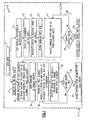
- Figure 1 illustrates an exemplary method 10 to design a broach tool for machining fir-tree slots 6 in titanium (Ti), steel, and nickel (Ni) based superalloys disks 8 ( Figure 2 ).
- the methodology 10, shown in Figure 1 is performed using an exemplary computing system 13 configured to perform the method 10.
- the method 10 provides a systematic way to predict the number of broach inserts in a tool set and the number of teeth per insert based on the provided disk material properties and microstructure (block 16) and geometrical model of the disk fir-tree slot (block 14), corresponding to data input 12 provided by a user. It should be appreciated that each block represented in the figures are representative of a method step.
- a computing system may be used to implement various functionality disclosed in this application.
- a computing system may include a processor, memory, and one or more input and/or output (I/O) device interface(s) that are communicatively coupled via a local interface.
- the local interface may include, for example but not limited to, one or more buses and/or other wired or wireless connections.
- the local interface may have additional elements, which, are omitted for simplicity, such as controllers, buffers (caches), drivers, repeaters, and receivers to enable communications.
- the local interface may include address, control, and/or data connections to enable appropriate communications among the aforementioned components.
- the processor may be a hardware device for executing software, particularly software stored in memory.
- the processor can be a custom made or commercially available processor, a central processing unit (CPU), an auxiliary processor among several processors associated with the computing system 13, a semiconductor based microprocessor (in the form of a microchip or chip set) or generally any device for executing software instructions.
- the memory may include any one or combination of volatile memory elements (e.g., random access memory (RAM, such as DRAM, SRAM, SDRAM, VRAM, etc.)) and/or nonvolatile memory elements (e.g., ROM, hard drive, tape, CD-ROM, etc.).
- volatile memory elements e.g., random access memory (RAM, such as DRAM, SRAM, SDRAM, VRAM, etc.)
- nonvolatile memory elements e.g., ROM, hard drive, tape, CD-ROM, etc.
- the memory may incorporate electronic, magnetic, optical, and/or other types of storage media. Note that the memory may also have a distributed architecture, where various components are situated remotely from one another, but can be accessed by the processor.
- the software in the memory may include one or more separate programs, each of which includes an ordered listing of executable instructions for implementing logical functions.
- a system component embodied as software may also be construed as a source program, executable program (object code), script, or any other entity comprising a set of instructions to be performed.
- the program is translated via a compiler, assembler, interpreter, or the like, which may or may not be included within the memory.
- the Input/Output devices that may be coupled to system I/O Interface(s) may include input devices, for example but not limited to, a keyboard, mouse, scanner, microphone, camera, proximity device, etc. Further, the Input/Output devices may also include output devices, for example but not limited to, a printer, display, etc. Finally, the Input/Output devices may further include devices that communicate both as inputs and outputs, for instance but not limited to, a modulator/demodulator (modem; for accessing another device, system, or network), a radio frequency (RF) or other transceiver, a telephonic interface, a bridge, a router, etc.
- modem for accessing another device, system, or network
- RF radio frequency
- the processor may be configured to execute software stored within the memory, to communicate data to and from the memory, and to generally control operations of the computing device pursuant to the software.
- Software in memory, in whole or in part, is read by the processor, perhaps buffered within the processor, and then executed.
- a design of experiments or a series of tests are performed to identify the minimum tooth rise in a finishing broaching stage before designing the tool.
- the exact rise may vary depending on the material microstructure.
- orthogonal cutting test may be performed on a lathe machine to identify the microstructure strained zone using optical microscopy or x-rays diffraction method. The orthogonal cutting tests are performed under different feed rates (chip thicknesses), speeds and make angles. Cutting forces, and residual stress and strain are measured, as indicated at block 20.
- the cutting force data identifies the effect of increasing feed rate or chip thickness on a total broaching load in the finishing stage.
- the measured forces in broaching of coarse-grained (average grain size of 55 ⁇ m) nickel based superalloy under different chip thickness representing the cutting forces do not increase significantly as the tooth rise (chip thickness) increases.
- One exemplary test indicated that an increase in the chip thickness from 12 ⁇ m to 50 ⁇ m increases the forces only by 14%.
- the residual stresses and strains, forces, and microstructure evolution at various cutting speeds is analyzed in a two-dimensional (2D) finite element model for defined minimum tooth rise (block 24).
- DEFORM or ABAQUS finite element program may be used for the 2D analysis to determine the residual strain and stresses induced on a machined surface of a material/alloy and used for further identifying of the optimum tooth rise in the finishing stage.
- DEFORM or ABAQUS finite element program may be used for the 2D analysis to determine the residual strain and stresses induced on a machined surface of a material/alloy and used for further identifying of the optimum tooth rise in the finishing stage.
- the depth of microstructure evolution under the machined surface is higher at lower chip thickness of 12.7 ⁇ m than that at higher chip thicknesses of 39 and 50 ⁇ m.
- the microstructure on the machined surface was strained and altered to a depth of 24 ⁇ m.
- the diffraction pattern of the same material indicated that the microstructure retains its original pattern after
- the minimum chip thickness for the broaching process in a finishing pass of the finishing stage should be higher than the depth of strained layer beneath the produced surface.
- the strained layer may be confined within the thickness of one to two average grain sizes of a workpiece material. If a finishing pass is performed through the strained layer, then changes in the deformation mode may cause shear banding deformation that result in localized changes in the strain rates as well as adiabatic heating. Such deformation inhomogeneties in turn may cause the formation of distorted layers such as white etching layers in Ni-based superalloys and steels or alpha-cases in Ti-based alloys.
- the tooth rise and cutting speed are selected (block 30) for application to a reverse engineering method (block 32) that defines the required number of broach inserts for the three stages based on the designed fir-tree slot geometry (block 14) within the tolerance and accuracy specified.
- a series of numerical simulations to model the broaching process may be specified to identify cutting speeds, and a multitude of broach insert parameters (e.g., rise per tooth, face/hook angle, and back-off angle, back angle tooth pitch, tooth thickness and tooth form (i.e., sketch), based on the values of hydrostatic pressure predicted for the specified disk material.
- Sets of rules are used to generate solid models for each broach insert, based upon data from the broach tool designer, in solid modeling environment such as, but not limited, the UNIGRAPHIC CAD environment (UG) (block 34). It should be appreciated that other suitable software programs may be used for solid modeling.
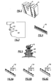
- the example solid model of fir-tree slot 6 in the disk 8 (shown in Figure 2 ) is imported into UG, and a finish insert is sketched having radii R1-R4, as shown at 44 in Figure 3 .
- a finish insert solid model 46 is created in UG from the sketch 44, as shown in Figure 4 , using an expressions list to update the number of teeth and pitch.
- solids models are created for semi-finish inserts 48 and rough inserts 50 shown in Figure 5 .
- Three example rough inserts 52, 54, 56 having progressively larger tooth rises are shown respectively in Figures 6a-6c .
- the solid models of the different broach inserts are then input to a finite element model such as, but not limited to, ANSYS finite element code to predict and map cutting forces, and then determine tool and lug deformation (block 36, Figure 1 ).
- the lugs are the portions of the disk that provide the slots. Lug deformation corresponds to slot deformation. It should be appreciated that other suitable software programs may be used for finite element modeling.
- the deformation of the disk is utilized in predicting instantaneous chip thickness and variation of the cutting forces and stresses on the tool and workpiece to prevent tool chipping and/or breakage.
- a procedure is devised to modify the broach insert geometry based upon the finite element analysis results (block 38).
- the desired tooth geometry for the insert has been achieved and is defined as the optimum tooth geometry for the insert (block 42). If the slot opening is outside the desired specification, then the finite element model is revised and the forces, stresses and slot deformation are reanalyzed (block 36).
- Solid modeling (UG) data 90 is read by the finite element environment (ANSYS) 92.
- Data from the finite element environment 92 is optimized using optimization code (FIPER) 94.
- the optimization results may be used to refine the broach tool corresponding to the solid modeling data 90.
- the methodology 10 achieves the broach insert design by changing the broach insert parameters including the pitch, and distribute tooth form to facilitate reducing slot deformation.
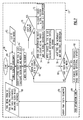
- FIG. 7 an exemplary procedure for determining the desired broach insert geometry according to block 38 in Figure 1 is illustrated.
- the solid models for the lug and tool (blocks 62, 64) are read by the ANSYS finite element environment (block 60).
- Information such as tool and workpiece material properties, workpiece (WP) force coefficients, broaching slash angles and lug thickness are also provided (block 88).
- the cutting edges are used to create the finite element model, and tooth rise and the width of cut are determined (block 64).
- One incremental movement of the tool is simulated (block 66). If the tool does not have a rise and contacts, then the procedure jumps to block 80 as discussed below.
- the tool has a rise and contacts the lug (block 68), then it is determined whether the first tooth is in contact with the lug (block 70). If the tooth rise is too small, for example, the tool will rub on the lug and generate heat that will distort the grain structure of the lug. If the first tooth of the broach insert is determined to be in contact with the lug, the forces, tool position and lug deformation are determined (block 72). If the first tooth of the broach insert is not in contact with the lug, then the lug deformation value is read by ANSYS (block 74). Then, the actual forces between the lug and tool are determined, and the force distribution is mapped. The forces from block 74 are applied to the tool and lug, and the deformation, stress and strain are determined (block 76). An additional incremental movement of the tool is then simulated and the new force distribution is mapped (block 78).
- FIPER modifies the tooth geometry (block 86), which is provided to UG (block 88) for use by ANSYS (block 60) for reanalysis of the new broach insert geometry.
- results 98 obtained from the FIPER optimization approach may be in the format presented generally at 96 in Figure 9 . Simulation results will identify the optimum tooth rise and allowable curvature that reduce stress concentration.
- a 2D finite element machining model is created to define the optimum tool edge preparation and cutting edge honing radius that facilitates reducing surface anomalies.
- An example of 2D finite element machining model is presented in Figures 10A-10C , which illustrate a tool 102 removing a chip 104 from the lug 8 at the slot 6.
- Figure 10A represents a model 100 illustrating a prediction of microstructure deformation.
- Figure 10B represents a model 106 illustrating a prediction of cutting temperature.
- Figure 10C represents a model 108 illustrating a prediction of hydrostatic pressure.
- the models 100, 106, 108 act as a check on the results of the broach insert design methodology 10.
- the edge preparation honed radius will be added to the tool design sheet.
- the tool solid model can then be fed to computer aided modeling (CAM) software to generate a computer numerically controlled (CNC) program for accurate grinding of the tooth geometry.
- CAM computer aided modeling
- CNC computer numerically controlled
- the solid model for the tool simplifies and automates the design process.
- the disclosed methodology also facilitates insuring quality, minimize the number of manufactured tool iterations, and reduce production time.
- the disclosed methodology generates broach tool design parameters that specify the value of the chip thickness or the rise per tooth for the finishing inserts based on the disk material behavior during broaching.
- the specified rise per tooth for the finishing inserts is customized to accommodate for material microstructure evolution during broaching. This value should exceed the average grain size of the workpiece.
- the disclosed methodology provides methods and systems for analysis of material microstructure to define chip thickness that facilitates reducing production of surface anomalies such as white etching layer cause by broaching.
- Test results indicate that the tooth rise for finishing and shaving passes are higher than the average grain size of the workpiece material for the coarse-grained alloys (average grain size larger than 25 ⁇ m) or higher than 32 ⁇ m for the fine-grained alloys (average grain size less than 25 ⁇ m).
- the disclosed methodology facilitates insuring that the tool engages with the lug and generates less strained material, which facilitates reducing the cutting force generated and consequently stress, strain and slot deflection.
Landscapes
- Engineering & Computer Science (AREA)
- Physics & Mathematics (AREA)
- Theoretical Computer Science (AREA)
- General Physics & Mathematics (AREA)
- Geometry (AREA)
- Evolutionary Computation (AREA)
- General Engineering & Computer Science (AREA)
- Computer Hardware Design (AREA)
- Mechanical Engineering (AREA)
- Human Computer Interaction (AREA)
- Manufacturing & Machinery (AREA)
- Automation & Control Theory (AREA)
- Computational Mathematics (AREA)
- Mathematical Analysis (AREA)
- Mathematical Optimization (AREA)
- Pure & Applied Mathematics (AREA)
- Milling, Broaching, Filing, Reaming, And Others (AREA)
Abstract
Description
- This disclosure relates to a method and systems for designing a broach tool used to machine components such as rotating disks used in aerospace applications.
- A gas turbine engine integrates a compressor and a turbine having components that rotate at high speeds, which subject the components to significant centrifugal loading during operations. One component that rotates at high speeds is a disk that carries multiple circumferentially arranged blades. The blades are commonly attached at an outer circumference of the disk through respective blade attachment slots. Each of the slots has a profile that corresponds with the root of the blade, and has a configuration designed to retain the blade in the slot during operation. The blade attachments slots are generally of a "fir-tree" configuration to increase the load bearing surface area of the disk. Broaching is a technique often utilized for forming fir-tree slots in gas turbine engine disks.
- In at least some known broaching processes, a broach tool includes a series of cutting teeth formed on a single solid bar or insert. The inserts and teeth are pulled through a workpiece to gradually remove material and form the desired slot opening. Each cutting tooth is typically slightly different from the adjacent cutting teeth. The fir-tree slots are generally formed in a three-stage broaching operation. Each stage may employ a broach tool including a set of up to thirty or more inserts. A rough shape of the slot is generally formed during an initial rough broaching stage. An intermediate broaching stage is used to form the intermediate shape of the slot. Finally, a finishing broaching stage is generally used to form the profile of the fir-tree slot.
- Several known design approaches have disclosed fir-tree/broach slot configurations and details of the geometric assimilation of lines, arcs, and angles for the purposes of reducing centrifugal forces, bending moments, and vibrations and the consequential peak stresses that result at the attachment points. However, the limitations of such known broaching processes that are associated with aerospace materials include excessive material strain hardening, surface microstructure alteration (such as white etched layer and bend microstructures), slot deformation, and ripple formation on the slot surfaces. The ripples and defects on the slot surfaces may lead to a decreased disk life because of fretting between the blade root and the disk surface during engine operation. In addition to the high cost of the broach tools and limited tool life, the design of known broach tools is based on tribunal knowledge of other materials. These known design methods result in high scrap rate and lower tool life because of the surface anomalies generated during finishing of the slot. Such part scrap rate is generally higher compared to other machining processes due to a compromised surface integrity if the broach tool is not designed properly to account for the progress of strain hardening during machining.
- What is needed is an approach and system for designing broach tools that facilitate reducing the undesirable effects of known broach design methods and systems.
- This disclosure relates to a design method used in manufacturing a broaching tool for cutting slots in aerospace disk applications. The method includes modeling geometry of the slot and the broach tool, which is based upon an initial minimum tooth rise that is determined empirically for the particular disk material. The number of broach inserts and teeth per insert is calculated, and the broach inserts are modeled. The stresses and deformation of the lug are calculated in a finite elements environment based upon simulated incremental broach tool movements. If the lug is not within specifications based upon design constraints, then the broach tool is revised and the simulations are repeated until the slot is within the desired specifications.
- These and other features of the disclosure can be best understood from the following specification and drawings, the following of which is a brief description.
-
-
Figure 1 is a flow chart depicting an example broach tool design methodology. -
Figure 2 is a schematic view of a fir-tree slot. -
Figure 3 is a schematic view of a tool sketch output from a CAD model. -
Figure 4 is a perspective view of an example finish insert from a solid model. -
Figure 5 is a plan view of example rough, semi-finish and finish inserts from the solid model. -
Figures 6A-6C are perspective views of different rough broach inserts having different tooth rises generated by the solid model. -
Figure 7 is a flow chart depicting an iterative routine for converging on a desired broach insert design. -
Figure 8 is a schematic view of the iterative routine illustrated more generally. -
Figure 9 is a schematic view illustrating the analysis and output of the example broach tool design methodology. -
Figures 10A-10C schematically depict a 2D analysis of a finite element machining model illustrating material microstructure, cutting temperature and hydrostatic pressure, respectively. -
Figure 1 illustrates anexemplary method 10 to design a broach tool for machining fir-tree slots 6 in titanium (Ti), steel, and nickel (Ni) based superalloys disks 8 (Figure 2 ). Themethodology 10, shown inFigure 1 , is performed using anexemplary computing system 13 configured to perform themethod 10. Themethod 10 provides a systematic way to predict the number of broach inserts in a tool set and the number of teeth per insert based on the provided disk material properties and microstructure (block 16) and geometrical model of the disk fir-tree slot (block 14), corresponding todata input 12 provided by a user. It should be appreciated that each block represented in the figures are representative of a method step. - It should be noted that a computing system may be used to implement various functionality disclosed in this application. In terms of hardware architecture, such a computing system may include a processor, memory, and one or more input and/or output (I/O) device interface(s) that are communicatively coupled via a local interface. The local interface may include, for example but not limited to, one or more buses and/or other wired or wireless connections. The local interface may have additional elements, which, are omitted for simplicity, such as controllers, buffers (caches), drivers, repeaters, and receivers to enable communications. Further, the local interface may include address, control, and/or data connections to enable appropriate communications among the aforementioned components.
- The processor may be a hardware device for executing software, particularly software stored in memory. The processor can be a custom made or commercially available processor, a central processing unit (CPU), an auxiliary processor among several processors associated with the
computing system 13, a semiconductor based microprocessor (in the form of a microchip or chip set) or generally any device for executing software instructions. - The memory may include any one or combination of volatile memory elements (e.g., random access memory (RAM, such as DRAM, SRAM, SDRAM, VRAM, etc.)) and/or nonvolatile memory elements (e.g., ROM, hard drive, tape, CD-ROM, etc.). Moreover, the memory may incorporate electronic, magnetic, optical, and/or other types of storage media. Note that the memory may also have a distributed architecture, where various components are situated remotely from one another, but can be accessed by the processor.
- The software in the memory may include one or more separate programs, each of which includes an ordered listing of executable instructions for implementing logical functions. A system component embodied as software may also be construed as a source program, executable program (object code), script, or any other entity comprising a set of instructions to be performed. When constructed as a source program, the program is translated via a compiler, assembler, interpreter, or the like, which may or may not be included within the memory.
- The Input/Output devices that may be coupled to system I/O Interface(s) may include input devices, for example but not limited to, a keyboard, mouse, scanner, microphone, camera, proximity device, etc. Further, the Input/Output devices may also include output devices, for example but not limited to, a printer, display, etc. Finally, the Input/Output devices may further include devices that communicate both as inputs and outputs, for instance but not limited to, a modulator/demodulator (modem; for accessing another device, system, or network), a radio frequency (RF) or other transceiver, a telephonic interface, a bridge, a router, etc.
- When the
computing system 13 is in operation, the processor may be configured to execute software stored within the memory, to communicate data to and from the memory, and to generally control operations of the computing device pursuant to the software. Software in memory, in whole or in part, is read by the processor, perhaps buffered within the processor, and then executed. - First, for each type of disk material and/or alloy, a design of experiments or a series of tests (block 18) are performed to identify the minimum tooth rise in a finishing broaching stage before designing the tool. The exact rise may vary depending on the material microstructure. For example, orthogonal cutting test may be performed on a lathe machine to identify the microstructure strained zone using optical microscopy or x-rays diffraction method. The orthogonal cutting tests are performed under different feed rates (chip thicknesses), speeds and make angles. Cutting forces, and residual stress and strain are measured, as indicated at
block 20. The cutting force data identifies the effect of increasing feed rate or chip thickness on a total broaching load in the finishing stage. - For example, the measured forces in broaching of coarse-grained (average grain size of 55µm) nickel based superalloy under different chip thickness representing the cutting forces do not increase significantly as the tooth rise (chip thickness) increases. One exemplary test indicated that an increase in the chip thickness from 12 µm to 50 µm increases the forces only by 14%. These results suggests that a tooth rise of 55 µm may be used to define a minimum tooth rise (block 22) when designing the broach tool for the finishing stage of the tested alloy.
- Next, the residual stresses and strains, forces, and microstructure evolution at various cutting speeds is analyzed in a two-dimensional (2D) finite element model for defined minimum tooth rise (block 24). For example, DEFORM or ABAQUS finite element program may be used for the 2D analysis to determine the residual strain and stresses induced on a machined surface of a material/alloy and used for further identifying of the optimum tooth rise in the finishing stage. For example, one test determined that the depth of microstructure evolution under the machined surface is higher at lower chip thickness of 12.7 µm than that at higher chip thicknesses of 39 and 50 µm. At the chip thickness of 12.7 µm, the microstructure on the machined surface was strained and altered to a depth of 24 µm. The diffraction pattern of the same material indicated that the microstructure retains its original pattern after a depth of 32 µm beneath the machined surface. It should be appreciated that other suitable software programs may be used for the 2D finite element analysis.
- Experimental data indicates that the minimum chip thickness for the broaching process in a finishing pass of the finishing stage should be higher than the depth of strained layer beneath the produced surface. In a coarse-grained material, the strained layer may be confined within the thickness of one to two average grain sizes of a workpiece material. If a finishing pass is performed through the strained layer, then changes in the deformation mode may cause shear banding deformation that result in localized changes in the strain rates as well as adiabatic heating. Such deformation inhomogeneties in turn may cause the formation of distorted layers such as white etching layers in Ni-based superalloys and steels or alpha-cases in Ti-based alloys.
- The above 2D analyses of the residual stresses and strains, forces, and microstructure evolution at various cutting speeds is conducted iteratively (block 28) to converge on a minimum tooth rise, Tm, and cutting speed that is within desired specifications (block 26). The desired specifications are defined by a broach tool designer, for example.
- If within the desired specification as determined, for example, by a slot designer, then the tooth rise and cutting speed are selected (block 30) for application to a reverse engineering method (block 32) that defines the required number of broach inserts for the three stages based on the designed fir-tree slot geometry (block 14) within the tolerance and accuracy specified. A series of numerical simulations to model the broaching process may be specified to identify cutting speeds, and a multitude of broach insert parameters (e.g., rise per tooth, face/hook angle, and back-off angle, back angle tooth pitch, tooth thickness and tooth form (i.e., sketch), based on the values of hydrostatic pressure predicted for the specified disk material.
- Sets of rules are used to generate solid models for each broach insert, based upon data from the broach tool designer, in solid modeling environment such as, but not limited, the UNIGRAPHIC CAD environment (UG) (block 34). It should be appreciated that other suitable software programs may be used for solid modeling. The example solid model of fir-
tree slot 6 in the disk 8 (shown inFigure 2 ) is imported into UG, and a finish insert is sketched having radii R1-R4, as shown at 44 inFigure 3 . A finish insertsolid model 46 is created in UG from thesketch 44, as shown inFigure 4 , using an expressions list to update the number of teeth and pitch. In a similar manner, solids models are created forsemi-finish inserts 48 andrough inserts 50 shown inFigure 5 . Three examplerough inserts Figures 6a-6c . - The solid models of the different broach inserts are then input to a finite element model such as, but not limited to, ANSYS finite element code to predict and map cutting forces, and then determine tool and lug deformation (block 36,
Figure 1 ). The lugs are the portions of the disk that provide the slots. Lug deformation corresponds to slot deformation. It should be appreciated that other suitable software programs may be used for finite element modeling. The deformation of the disk is utilized in predicting instantaneous chip thickness and variation of the cutting forces and stresses on the tool and workpiece to prevent tool chipping and/or breakage. With continuing reference toFigure 1 , a procedure is devised to modify the broach insert geometry based upon the finite element analysis results (block 38). If the slot opening is within the desired specification (block 40) as determined by customary design practice, then the desired tooth geometry for the insert has been achieved and is defined as the optimum tooth geometry for the insert (block 42). If the slot opening is outside the desired specification, then the finite element model is revised and the forces, stresses and slot deformation are reanalyzed (block 36). - The overall iteration approach used in the
methodology 10 is schematically illustrated inFigures 8 and10 . Solid modeling (UG)data 90 is read by the finite element environment (ANSYS) 92. Data from thefinite element environment 92 is optimized using optimization code (FIPER) 94. The optimization results may be used to refine the broach tool corresponding to thesolid modeling data 90. Themethodology 10 achieves the broach insert design by changing the broach insert parameters including the pitch, and distribute tooth form to facilitate reducing slot deformation. - As shown in
Figure 7 , an exemplary procedure for determining the desired broach insert geometry according to block 38 inFigure 1 is illustrated. The solid models for the lug and tool (blocks 62, 64) are read by the ANSYS finite element environment (block 60). Information such as tool and workpiece material properties, workpiece (WP) force coefficients, broaching slash angles and lug thickness are also provided (block 88). The cutting edges are used to create the finite element model, and tooth rise and the width of cut are determined (block 64). One incremental movement of the tool is simulated (block 66). If the tool does not have a rise and contacts, then the procedure jumps to block 80 as discussed below. If the tool has a rise and contacts the lug (block 68), then it is determined whether the first tooth is in contact with the lug (block 70). If the tooth rise is too small, for example, the tool will rub on the lug and generate heat that will distort the grain structure of the lug. If the first tooth of the broach insert is determined to be in contact with the lug, the forces, tool position and lug deformation are determined (block 72). If the first tooth of the broach insert is not in contact with the lug, then the lug deformation value is read by ANSYS (block 74). Then, the actual forces between the lug and tool are determined, and the force distribution is mapped. The forces fromblock 74 are applied to the tool and lug, and the deformation, stress and strain are determined (block 76). An additional incremental movement of the tool is then simulated and the new force distribution is mapped (block 78). - If the last tooth motion is greater than the lug width (block 80), then the forces, deflection and stresses are plotted and arranged in a table (block 82). These values are then run through an optimization code (block 84 in
Figure 7 , at 94 inFigure 8 ), such as FIPER, as a check on the limits and design constraints. If the values are outside the limit, FIPER modifies the tooth geometry (block 86), which is provided to UG (block 88) for use by ANSYS (block 60) for reanalysis of the new broach insert geometry. - The
results 98 obtained from the FIPER optimization approach (block 84) may be in the format presented generally at 96 inFigure 9 . Simulation results will identify the optimum tooth rise and allowable curvature that reduce stress concentration. - To finalize the broach tool design, a 2D finite element machining model is created to define the optimum tool edge preparation and cutting edge honing radius that facilitates reducing surface anomalies. An example of 2D finite element machining model is presented in
Figures 10A-10C , which illustrate atool 102 removing achip 104 from thelug 8 at theslot 6.Figure 10A represents amodel 100 illustrating a prediction of microstructure deformation.Figure 10B represents amodel 106 illustrating a prediction of cutting temperature.Figure 10C represents amodel 108 illustrating a prediction of hydrostatic pressure. Themodels insert design methodology 10. - The edge preparation honed radius will be added to the tool design sheet. The tool solid model can then be fed to computer aided modeling (CAM) software to generate a computer numerically controlled (CNC) program for accurate grinding of the tooth geometry.
- The solid model for the tool simplifies and automates the design process. The disclosed methodology also facilitates insuring quality, minimize the number of manufactured tool iterations, and reduce production time. The disclosed methodology generates broach tool design parameters that specify the value of the chip thickness or the rise per tooth for the finishing inserts based on the disk material behavior during broaching. The specified rise per tooth for the finishing inserts is customized to accommodate for material microstructure evolution during broaching. This value should exceed the average grain size of the workpiece. The disclosed methodology provides methods and systems for analysis of material microstructure to define chip thickness that facilitates reducing production of surface anomalies such as white etching layer cause by broaching. Test results indicate that the tooth rise for finishing and shaving passes are higher than the average grain size of the workpiece material for the coarse-grained alloys (average grain size larger than 25 µm) or higher than 32 µm for the fine-grained alloys (average grain size less than 25 µm). The disclosed methodology facilitates insuring that the tool engages with the lug and generates less strained material, which facilitates reducing the cutting force generated and consequently stress, strain and slot deflection.
- Although example embodiments have been disclosed, a worker of ordinary skill in this art would recognize that certain modifications would come within the scope of the claims. For that reason, the following claims should be studied to determine their true scope and content.
Claims (14)
- A method (10) for designing a broaching tool comprising the steps of:a) providing (14) a geometry of a slot to be broached;b) providing (16-30) a material dependent initial minimum tooth rise for a broach tool that includes multiple broach inserts;c) calculating (32) a number of broach inserts and teeth per insert based upon steps a) and b);d) solid modeling (34) the broach inserts from step c);e) calculating (36) the stresses on the broach tool and deformation of the slot;f) determining (40) whether the slot dimensions are within desired specifications based upon step e); andg) revising (38) the broach tool if the slot is outside the desired specifications, and performing steps c)-g) until the slot is within desired specifications.
- The method according to claim 1, wherein the geometry is a solid model of the slot and the broach inserts.
- The method according to claim 2, wherein step a) is performed in a solid model environment.
- The method according to claim 3, wherein step d) is performed in the solid model environment.
- The method according to claim 1, 2, 3 or 4, wherein step b) includes performing cutting tests to empirically determine microstructure strained zones at different feed rates for a material of the slot.
- The method according to claim 5, wherein the broach inserts include finish, semi-finish and rough broach inserts, and step b) is performed to determine the initial minimum tooth rise for the finish broach inserts.
- The method according to claim 6, wherein the initial minimum tooth rise is greater than 30 µm for a coarse-grained alloy material with an average grain size larger than 25 µm; and/or wherein the initial minimum tooth rise is greater than 32 µm for a fine-grained alloy material with an average grain size smaller than 25 µm.
- The method according to any preceding claim, wherein step e) includes importing data from steps a) and d) into a finite element modeling environment.
- The method according to claim 8, wherein step e) includes simulating an incremental movement of the broach tool to determine forces on the broach tool and the slot.
- The method according to claim 9, wherein step e) includes calculating deformation, stress and strain in the slot and on a broach tool edge.
- The method according to claim 10, wherein step e) includes simulating an additional incremental movement of the broach tool to determine new forces on the broach tool and the slot.
- The method according to any preceding claim, wherein step e) includes outputting deflections and stresses in the slot and wherein steps f) and g) include receiving the outputs and reevaluating design constraints of the broach tool and modifying broach tool geometry based upon design parameters.
- The method according to any preceding claim, wherein step f) includes modeling microstructure deformation at a cutting chip in the slot; and/or wherein step f) includes modeling cutting temperature at a cutting chip in the slot; and/or wherein step f) includes modeling hydrostatic pressure at a cutting chip in the slot to define possible generation of undesired surface anomalies.
- A system (13) for designing a broaching tool comprising:a processor configured to provide a geometry of a slot to be broached, to provide a material dependent initial minimum tooth rise for a broach tool that includes multiple broach inserts, to calculate a number of broach inserts and teeth per insert based upon the geometry and the material dependent initial tooth rise, to solid model the broach inserts from the calculated number of broach inserts and teeth per insert, to calculate the stresses on the broach tool and deformation of the slot, to determine whether the slot dimensions are within desired specifications based upon the calculated stresses and deformation; andwherein the processor is configured to revise the broach tool if the slot is outside the desired specifications, and calculate a number of broach inserts and teeth per insert, solid model the broach inserts from the calculated number of broach inserts and teeth per insert, calculate the stresses on the broach tool and deformation of the slot, determine whether the slot dimensions are within desired specifications based upon the calculated stresses and deformation, and revise the broach tool if the slot is outside the desired specifications until the slot is within the desired specifications.
Applications Claiming Priority (1)
| Application Number | Priority Date | Filing Date | Title |
|---|---|---|---|
| US12/120,319 US8000942B2 (en) | 2008-05-14 | 2008-05-14 | Broach tool design methodology and systems |
Publications (3)
| Publication Number | Publication Date |
|---|---|
| EP2119521A2 true EP2119521A2 (en) | 2009-11-18 |
| EP2119521A3 EP2119521A3 (en) | 2013-03-27 |
| EP2119521B1 EP2119521B1 (en) | 2016-07-27 |
Family
ID=40957762
Family Applications (1)
| Application Number | Title | Priority Date | Filing Date |
|---|---|---|---|
| EP09250881.1A Ceased EP2119521B1 (en) | 2008-05-14 | 2009-03-27 | Broach tool design method and systems |
Country Status (2)
| Country | Link |
|---|---|
| US (1) | US8000942B2 (en) |
| EP (1) | EP2119521B1 (en) |
Cited By (7)
| Publication number | Priority date | Publication date | Assignee | Title |
|---|---|---|---|---|
| CN102962513A (en) * | 2012-11-14 | 2013-03-13 | 沈阳黎明航空发动机(集团)有限责任公司 | High-accuracy mortise broaching processing method for turbine disk made of powder high-temperature alloy material |
| CN103071853A (en) * | 2012-09-26 | 2013-05-01 | 沈阳黎明航空发动机(集团)有限责任公司 | Broaching method and special tool for high-accuracy small-sized mortises |
| WO2013175478A3 (en) * | 2012-05-24 | 2014-04-17 | Gershon System Ltd. | Method for designing a cutting edge of a cutting tool, cutting tools comprising the same, and cutting elements with multiple such cutting portions |
| US9975183B2 (en) | 2013-09-17 | 2018-05-22 | Gershon System Ltd. | Cutting element and a method of cutting using the same |
| CN108920876A (en) * | 2018-08-01 | 2018-11-30 | 中南大学 | A kind of optimization method of turbine disc mortise broaching tool geometry |
| FR3123581A1 (en) * | 2021-06-02 | 2022-12-09 | Safran Aircraft Engines | CUTTING FORCE MEASUREMENT DURING A BROACHING TEST |
| CN117592223A (en) * | 2024-01-18 | 2024-02-23 | 中国科学院工程热物理研究所 | An intelligent design method for hole processing tools for aerospace materials |
Families Citing this family (12)
| Publication number | Priority date | Publication date | Assignee | Title |
|---|---|---|---|---|
| US20130116817A1 (en) * | 2011-11-04 | 2013-05-09 | United Technologies Corporation | System and method for machining and inspecting a workpiece |
| US9718154B2 (en) * | 2012-01-18 | 2017-08-01 | United Technologies Corporation | Slot machining |
| US9366145B2 (en) | 2012-08-24 | 2016-06-14 | United Technologies Corporation | Turbine engine rotor assembly |
| US9656335B2 (en) | 2013-03-08 | 2017-05-23 | United Technologies Corporation | Broach tool rake face with a tailored surface topography |
| US9892219B2 (en) * | 2014-01-28 | 2018-02-13 | Rolls-Royce Corporation | Using fracture mechanism maps to predict time-dependent crack growth behavior under dwell conditions |
| US10311180B2 (en) * | 2014-07-15 | 2019-06-04 | Dassault Systemes Simulia Corp. | System and method of recovering Lagrange multipliers in modal dynamic analysis |
| JP6345617B2 (en) * | 2015-03-05 | 2018-06-20 | 株式会社神戸製鋼所 | Residual stress estimation method and residual stress estimation apparatus |
| JP6345618B2 (en) * | 2015-03-05 | 2018-06-20 | 株式会社神戸製鋼所 | Residual stress estimation method and residual stress estimation apparatus |
| US10061878B2 (en) | 2015-12-22 | 2018-08-28 | Dassault Systemes Simulia Corp. | Effectively solving structural dynamics problems with modal damping in physical coordinates |
| JP7486115B2 (en) * | 2020-03-12 | 2024-05-17 | 三菱重工業株式会社 | Low-toughness workpiece cutting device, low-toughness workpiece manufacturing method, and low-toughness workpiece manufacturing program |
| CN115178790A (en) * | 2021-04-02 | 2022-10-14 | 中国航发商用航空发动机有限责任公司 | Method for controlling machining process of surface integrity of mortise |
| CN119772256B (en) * | 2025-03-12 | 2025-05-16 | 嘉兴恒瑞动力有限公司 | Dual-station interactive platform selection system based on multi-intelligent system |
Citations (1)
| Publication number | Priority date | Publication date | Assignee | Title |
|---|---|---|---|---|
| US4841820A (en) | 1987-04-13 | 1989-06-27 | General Motors Corporation | Method of designing a turn broach |
Family Cites Families (17)
| Publication number | Priority date | Publication date | Assignee | Title |
|---|---|---|---|---|
| GB2030657B (en) | 1978-09-30 | 1982-08-11 | Rolls Royce | Blade for gas turbine engine |
| US4243347A (en) | 1979-02-28 | 1981-01-06 | General Electric Company | Broaching assembly having disposable carbide inserts |
| US4767274A (en) | 1986-12-29 | 1988-08-30 | United Technologies Corporation | Multiple lug blade to disk attachment |
| US4824328A (en) | 1987-05-22 | 1989-04-25 | Westinghouse Electric Corp. | Turbine blade attachment |
| US5135339A (en) | 1991-01-29 | 1992-08-04 | Carboloy Inc. | Broaching tool |
| US5628589A (en) | 1994-05-24 | 1997-05-13 | J. P. Tool, Inc. | Internal pull broach with indexable inserts |
| US5688108A (en) | 1995-08-01 | 1997-11-18 | Allison Engine Company, Inc. | High temperature rotor blade attachment |
| GB9606963D0 (en) | 1996-04-02 | 1996-06-05 | Rolls Royce Plc | A root attachment for a turbomachine blade |
| US6371468B1 (en) | 1999-12-17 | 2002-04-16 | United Technologies Research Center | Universal workpiece holder |
| US6302651B1 (en) | 1999-12-29 | 2001-10-16 | United Technologies Corporation | Blade attachment configuration |
| US6767168B2 (en) | 2000-06-04 | 2004-07-27 | Rolls-Royce Corporation | Method and apparatus for forming openings in a workpiece |
| US6558086B1 (en) | 2000-07-14 | 2003-05-06 | Kennametal Inc. | Broach for use in performing machining operations |
| US20030223831A1 (en) * | 2002-06-03 | 2003-12-04 | Viens Daniel V. | Methodology and tool design for high speed machining |
| US7905709B2 (en) | 2004-02-10 | 2011-03-15 | General Electric Company | Advanced firtree and broach slot forms for turbine stage 1 and 2 buckets and rotor wheels |
| US7156621B2 (en) | 2004-05-14 | 2007-01-02 | Pratt & Whitney Canada Corp. | Blade fixing relief mismatch |
| US7240562B2 (en) * | 2004-05-25 | 2007-07-10 | Utah State University | Method for modeling material constitutive behavior |
| US8234771B2 (en) * | 2007-03-21 | 2012-08-07 | General Electric Company | Method and system for machining an array of components |
-
2008
- 2008-05-14 US US12/120,319 patent/US8000942B2/en active Active
-
2009
- 2009-03-27 EP EP09250881.1A patent/EP2119521B1/en not_active Ceased
Patent Citations (1)
| Publication number | Priority date | Publication date | Assignee | Title |
|---|---|---|---|---|
| US4841820A (en) | 1987-04-13 | 1989-06-27 | General Motors Corporation | Method of designing a turn broach |
Cited By (11)
| Publication number | Priority date | Publication date | Assignee | Title |
|---|---|---|---|---|
| WO2013175478A3 (en) * | 2012-05-24 | 2014-04-17 | Gershon System Ltd. | Method for designing a cutting edge of a cutting tool, cutting tools comprising the same, and cutting elements with multiple such cutting portions |
| US10201856B2 (en) | 2012-05-24 | 2019-02-12 | Gershon System Ltd. | Method for designing a cutting edge of a cutting tool, cutting tools comprising the same, and cutting elements with multiple such cutting portions |
| CN103071853A (en) * | 2012-09-26 | 2013-05-01 | 沈阳黎明航空发动机(集团)有限责任公司 | Broaching method and special tool for high-accuracy small-sized mortises |
| CN103071853B (en) * | 2012-09-26 | 2015-03-25 | 沈阳黎明航空发动机(集团)有限责任公司 | Broaching method and special tool for high-accuracy small-sized mortises |
| CN102962513A (en) * | 2012-11-14 | 2013-03-13 | 沈阳黎明航空发动机(集团)有限责任公司 | High-accuracy mortise broaching processing method for turbine disk made of powder high-temperature alloy material |
| US9975183B2 (en) | 2013-09-17 | 2018-05-22 | Gershon System Ltd. | Cutting element and a method of cutting using the same |
| CN108920876A (en) * | 2018-08-01 | 2018-11-30 | 中南大学 | A kind of optimization method of turbine disc mortise broaching tool geometry |
| CN108920876B (en) * | 2018-08-01 | 2023-03-31 | 中南大学 | Optimization method for geometric structure of turbine disc mortise broach |
| FR3123581A1 (en) * | 2021-06-02 | 2022-12-09 | Safran Aircraft Engines | CUTTING FORCE MEASUREMENT DURING A BROACHING TEST |
| CN117592223A (en) * | 2024-01-18 | 2024-02-23 | 中国科学院工程热物理研究所 | An intelligent design method for hole processing tools for aerospace materials |
| CN117592223B (en) * | 2024-01-18 | 2024-04-16 | 中国科学院工程热物理研究所 | Intelligent design method of hole machining tool for aerospace materials |
Also Published As
| Publication number | Publication date |
|---|---|
| EP2119521B1 (en) | 2016-07-27 |
| US8000942B2 (en) | 2011-08-16 |
| US20090287458A1 (en) | 2009-11-19 |
| EP2119521A3 (en) | 2013-03-27 |
Similar Documents
| Publication | Publication Date | Title |
|---|---|---|
| EP2119521B1 (en) | Broach tool design method and systems | |
| US7870792B2 (en) | Forming limit strain analysis | |
| Soori et al. | Minimization of deflection error in five axis milling of impeller blades | |
| CN114730172B (en) | Computer-aided design method, computer-aided design system, and computer-readable medium for hybrid additive and subtractive manufacturing | |
| Li et al. | Simulation-based solid carbide end mill design and geometry optimization | |
| Yao et al. | Machining deformation prediction of large fan blades based on loading uneven residual stress | |
| CN114509991A (en) | Numerical control machine tool cutting stability prediction and optimization method considering parameter uncertainty | |
| Khaimovich | Computer-aided design of blank forging production facilities for aircraft engine compressor blades | |
| Vogtel et al. | Automatic broaching tool design by technological and geometrical optimization | |
| CN112784451A (en) | Thin-wall part machining deformation prediction method based on finite element and support vector machine | |
| Urbikain Pelayo et al. | Stability charts with large curve-flute end-mills for thin-walled workpieces | |
| Krimpenis et al. | Assessment of sculptured surface milling strategies using design of experiments | |
| Bailey et al. | Generic simulation approach for multi-axis machining, part 2: model calibration and feed rate scheduling | |
| Li et al. | Intelligent design method and system of trimming block for stamping dies of complex automotive panels | |
| Tekkaya et al. | Surface reconstruction for incremental forming | |
| CN111390299B (en) | Method for predicting machining deformation of floating support friction plate | |
| Budak | Machining process improvement through process twins | |
| Iklodi et al. | Analytical and numerical optimization of broaching tool tooth distribution | |
| Bergs et al. | Modeling of process-induced geometrical deviation in broaching for fir-tree slots | |
| Ozlu et al. | Simulation of broaching operations for tool design optimization | |
| Ozturk et al. | Analytical methods for increased productivity in five-axis ball-end milling | |
| CN115470583A (en) | A method for obtaining optimal machining parameters of cantilever parts based on numerical simulation | |
| JP5686975B2 (en) | Point sequence generation method, point sequence generation program, point sequence generation device, and machine tool provided with the same | |
| CN118734496B (en) | A method for determining residual stress control region of aeroengine blades | |
| Tapoglou et al. | Influence of machining data on developed cutting forces in gear hobbing |
Legal Events
| Date | Code | Title | Description |
|---|---|---|---|
| PUAI | Public reference made under article 153(3) epc to a published international application that has entered the european phase |
Free format text: ORIGINAL CODE: 0009012 |
|
| AK | Designated contracting states |
Kind code of ref document: A2 Designated state(s): AT BE BG CH CY CZ DE DK EE ES FI FR GB GR HR HU IE IS IT LI LT LU LV MC MK MT NL NO PL PT RO SE SI SK TR |
|
| AX | Request for extension of the european patent |
Extension state: AL BA RS |
|
| PUAL | Search report despatched |
Free format text: ORIGINAL CODE: 0009013 |
|
| AK | Designated contracting states |
Kind code of ref document: A3 Designated state(s): AT BE BG CH CY CZ DE DK EE ES FI FR GB GR HR HU IE IS IT LI LT LU LV MC MK MT NL NO PL PT RO SE SI SK TR |
|
| AX | Request for extension of the european patent |
Extension state: AL BA RS |
|
| RIC1 | Information provided on ipc code assigned before grant |
Ipc: B23D 43/00 20060101AFI20130215BHEP |
|
| 17P | Request for examination filed |
Effective date: 20130927 |
|
| RBV | Designated contracting states (corrected) |
Designated state(s): AT BE BG CH CY CZ DE DK EE ES FI FR GB GR HR HU IE IS IT LI LT LU LV MC MK MT NL NO PL PT RO SE SI SK TR |
|
| AKX | Designation fees paid |
Designated state(s): DE GB |
|
| 17Q | First examination report despatched |
Effective date: 20140912 |
|
| GRAP | Despatch of communication of intention to grant a patent |
Free format text: ORIGINAL CODE: EPIDOSNIGR1 |
|
| INTG | Intention to grant announced |
Effective date: 20160317 |
|
| GRAS | Grant fee paid |
Free format text: ORIGINAL CODE: EPIDOSNIGR3 |
|
| GRAA | (expected) grant |
Free format text: ORIGINAL CODE: 0009210 |
|
| AK | Designated contracting states |
Kind code of ref document: B1 Designated state(s): DE GB |
|
| REG | Reference to a national code |
Ref country code: GB Ref legal event code: FG4D |
|
| REG | Reference to a national code |
Ref country code: DE Ref legal event code: R096 Ref document number: 602009039948 Country of ref document: DE |
|
| RAP2 | Party data changed (patent owner data changed or rights of a patent transferred) |
Owner name: UNITED TECHNOLOGIES CORPORATION |
|
| REG | Reference to a national code |
Ref country code: DE Ref legal event code: R097 Ref document number: 602009039948 Country of ref document: DE |
|
| PLBE | No opposition filed within time limit |
Free format text: ORIGINAL CODE: 0009261 |
|
| STAA | Information on the status of an ep patent application or granted ep patent |
Free format text: STATUS: NO OPPOSITION FILED WITHIN TIME LIMIT |
|
| 26N | No opposition filed |
Effective date: 20170502 |
|
| REG | Reference to a national code |
Ref country code: DE Ref legal event code: R082 Ref document number: 602009039948 Country of ref document: DE Representative=s name: SCHMITT-NILSON SCHRAUD WAIBEL WOHLFROM PATENTA, DE |
|
| REG | Reference to a national code |
Ref country code: DE Ref legal event code: R081 Ref document number: 602009039948 Country of ref document: DE Owner name: RAYTHEON TECHNOLOGIES CORPORATION (N.D.GES.D.S, US Free format text: FORMER OWNER: UNITED TECHNOLOGIES CORPORATION, HARTFORD, CONN., US |
|
| PGFP | Annual fee paid to national office [announced via postgrant information from national office to epo] |
Ref country code: GB Payment date: 20230221 Year of fee payment: 15 Ref country code: DE Payment date: 20230221 Year of fee payment: 15 |
|
| P01 | Opt-out of the competence of the unified patent court (upc) registered |
Effective date: 20230519 |
|
| REG | Reference to a national code |
Ref country code: DE Ref legal event code: R119 Ref document number: 602009039948 Country of ref document: DE |
|
| GBPC | Gb: european patent ceased through non-payment of renewal fee |
Effective date: 20240327 |
|
| PG25 | Lapsed in a contracting state [announced via postgrant information from national office to epo] |
Ref country code: DE Free format text: LAPSE BECAUSE OF NON-PAYMENT OF DUE FEES Effective date: 20241001 |
|
| PG25 | Lapsed in a contracting state [announced via postgrant information from national office to epo] |
Ref country code: GB Free format text: LAPSE BECAUSE OF NON-PAYMENT OF DUE FEES Effective date: 20240327 |
|
| PG25 | Lapsed in a contracting state [announced via postgrant information from national office to epo] |
Ref country code: GB Free format text: LAPSE BECAUSE OF NON-PAYMENT OF DUE FEES Effective date: 20240327 Ref country code: DE Free format text: LAPSE BECAUSE OF NON-PAYMENT OF DUE FEES Effective date: 20241001 |