EP2119060B1 - Contrôle d'un réseau optique - Google Patents
Contrôle d'un réseau optique Download PDFInfo
- Publication number
- EP2119060B1 EP2119060B1 EP08709524.6A EP08709524A EP2119060B1 EP 2119060 B1 EP2119060 B1 EP 2119060B1 EP 08709524 A EP08709524 A EP 08709524A EP 2119060 B1 EP2119060 B1 EP 2119060B1
- Authority
- EP
- European Patent Office
- Prior art keywords
- optical
- connector
- connector apparatus
- test
- network
- Prior art date
- Legal status (The legal status is an assumption and is not a legal conclusion. Google has not performed a legal analysis and makes no representation as to the accuracy of the status listed.)
- Active
Links
- 238000012360 testing method Methods 0.000 title claims description 118
- 230000003287 optical effect Effects 0.000 title claims description 92
- 238000004891 communication Methods 0.000 claims description 13
- 238000000034 method Methods 0.000 claims description 10
- 238000012806 monitoring device Methods 0.000 claims 1
- 238000010998 test method Methods 0.000 claims 1
- 238000012544 monitoring process Methods 0.000 description 28
- 238000011144 upstream manufacturing Methods 0.000 description 27
- 239000000835 fiber Substances 0.000 description 24
- 230000005540 biological transmission Effects 0.000 description 16
- 239000013307 optical fiber Substances 0.000 description 13
- 210000004027 cell Anatomy 0.000 description 11
- 238000001514 detection method Methods 0.000 description 6
- 238000004146 energy storage Methods 0.000 description 5
- 238000005259 measurement Methods 0.000 description 5
- 230000006870 function Effects 0.000 description 4
- 230000004044 response Effects 0.000 description 4
- 230000008901 benefit Effects 0.000 description 3
- 238000006243 chemical reaction Methods 0.000 description 3
- 238000013461 design Methods 0.000 description 3
- 238000012545 processing Methods 0.000 description 3
- 230000002829 reductive effect Effects 0.000 description 3
- 239000004065 semiconductor Substances 0.000 description 3
- 229910000530 Gallium indium arsenide Inorganic materials 0.000 description 2
- 238000013459 approach Methods 0.000 description 2
- 238000013142 basic testing Methods 0.000 description 2
- 239000003990 capacitor Substances 0.000 description 2
- 230000008859 change Effects 0.000 description 2
- 230000008878 coupling Effects 0.000 description 2
- 238000010168 coupling process Methods 0.000 description 2
- 238000005859 coupling reaction Methods 0.000 description 2
- 238000002405 diagnostic procedure Methods 0.000 description 2
- 238000005516 engineering process Methods 0.000 description 2
- 230000007613 environmental effect Effects 0.000 description 2
- 238000003780 insertion Methods 0.000 description 2
- 230000037431 insertion Effects 0.000 description 2
- 239000000463 material Substances 0.000 description 2
- 230000008569 process Effects 0.000 description 2
- 239000000523 sample Substances 0.000 description 2
- RYGMFSIKBFXOCR-UHFFFAOYSA-N Copper Chemical compound [Cu] RYGMFSIKBFXOCR-UHFFFAOYSA-N 0.000 description 1
- 230000003321 amplification Effects 0.000 description 1
- 230000008033 biological extinction Effects 0.000 description 1
- 229910052802 copper Inorganic materials 0.000 description 1
- 239000010949 copper Substances 0.000 description 1
- 238000012937 correction Methods 0.000 description 1
- 210000002858 crystal cell Anatomy 0.000 description 1
- 230000001934 delay Effects 0.000 description 1
- 238000011161 development Methods 0.000 description 1
- 230000018109 developmental process Effects 0.000 description 1
- 239000000428 dust Substances 0.000 description 1
- 230000000694 effects Effects 0.000 description 1
- 230000005672 electromagnetic field Effects 0.000 description 1
- 239000005262 ferroelectric liquid crystals (FLCs) Substances 0.000 description 1
- 238000005286 illumination Methods 0.000 description 1
- 230000003116 impacting effect Effects 0.000 description 1
- 230000002452 interceptive effect Effects 0.000 description 1
- 230000000670 limiting effect Effects 0.000 description 1
- 239000004973 liquid crystal related substance Substances 0.000 description 1
- 238000012423 maintenance Methods 0.000 description 1
- 238000012986 modification Methods 0.000 description 1
- 230000004048 modification Effects 0.000 description 1
- 238000003199 nucleic acid amplification method Methods 0.000 description 1
- 230000000737 periodic effect Effects 0.000 description 1
- 230000009467 reduction Effects 0.000 description 1
- 230000000717 retained effect Effects 0.000 description 1
- 230000002000 scavenging effect Effects 0.000 description 1
- 230000003068 static effect Effects 0.000 description 1
- 239000000758 substrate Substances 0.000 description 1
- 239000010409 thin film Substances 0.000 description 1
Images


Classifications
-
- H—ELECTRICITY
- H04—ELECTRIC COMMUNICATION TECHNIQUE
- H04B—TRANSMISSION
- H04B10/00—Transmission systems employing electromagnetic waves other than radio-waves, e.g. infrared, visible or ultraviolet light, or employing corpuscular radiation, e.g. quantum communication
- H04B10/07—Arrangements for monitoring or testing transmission systems; Arrangements for fault measurement of transmission systems
- H04B10/075—Arrangements for monitoring or testing transmission systems; Arrangements for fault measurement of transmission systems using an in-service signal
- H04B10/077—Arrangements for monitoring or testing transmission systems; Arrangements for fault measurement of transmission systems using an in-service signal using a supervisory or additional signal
- H04B10/0779—Monitoring line transmitter or line receiver equipment
-
- H—ELECTRICITY
- H04—ELECTRIC COMMUNICATION TECHNIQUE
- H04B—TRANSMISSION
- H04B10/00—Transmission systems employing electromagnetic waves other than radio-waves, e.g. infrared, visible or ultraviolet light, or employing corpuscular radiation, e.g. quantum communication
- H04B10/07—Arrangements for monitoring or testing transmission systems; Arrangements for fault measurement of transmission systems
- H04B10/075—Arrangements for monitoring or testing transmission systems; Arrangements for fault measurement of transmission systems using an in-service signal
- H04B10/079—Arrangements for monitoring or testing transmission systems; Arrangements for fault measurement of transmission systems using an in-service signal using measurements of the data signal
- H04B10/0799—Monitoring line transmitter or line receiver equipment
-
- H—ELECTRICITY
- H04—ELECTRIC COMMUNICATION TECHNIQUE
- H04B—TRANSMISSION
- H04B10/00—Transmission systems employing electromagnetic waves other than radio-waves, e.g. infrared, visible or ultraviolet light, or employing corpuscular radiation, e.g. quantum communication
- H04B10/80—Optical aspects relating to the use of optical transmission for specific applications, not provided for in groups H04B10/03 - H04B10/70, e.g. optical power feeding or optical transmission through water
- H04B10/801—Optical aspects relating to the use of optical transmission for specific applications, not provided for in groups H04B10/03 - H04B10/70, e.g. optical power feeding or optical transmission through water using optical interconnects, e.g. light coupled isolators, circuit board interconnections
Definitions
- the present invention relates to testing an optical network, in particular using a test device that is releasably connectable to connector apparatus.
- PONs Passive Optical Networks
- data is broadcast from a head end to a plurality of terminals in a downstream direction.
- data is passively multiplexed.
- the terminals, which transmit optical data upstream to the head end, are normally configured to transmit data in response to scheduling instructions from the head end.
- the scheduling instructions control the timing of the data transmissions from the terminals such that data from different terminals is unlikely to overlap.
- the terminals are normally installed within customer premises, and will normally be connected to the optical network outside the premises by a standard plug and socket connector.
- Example optical network systems are described in US 4278850 and US 2003/021580 .
- the former describes the use of optical transmission line repeaters, each of which has an identifier which allows for the error rate of each repeater to be monitored.
- the latter describes automatic discovery of cable interconnection topology in an optical network by storing identification information regarding components therein.
- a network operator can be useful for a network operator to test the network centrally, for example at the head end, by monitoring signals from the terminals.
- An example of such a system which allows detection of a faulty "rogue" terminal which transmits in the wrong time slot is described in US 2006/268759 .
- a power meter located at the head end detects and measures the power levels of upstream data packets arriving from the plurality of terminals during a sequence of transmission time slots. This enables the detection of rogue signals and identification of the rogue terminal.
- devices connected to optical networks are electrically powered from the mains supply. Although it is known to derive optical power from an optical source using a photovoltaic device or other solar cell, this is not always convenient.
- a testing system having: connector apparatus including a socket, for releasably connecting an optical network to a terminal unit, the connector apparatus having an identifier associated therewith, and an identifier circuit for providing an identification signal, which identification signal is indicative of the identifier associated with the connector apparatus; characterised in that the system further comprises a test device including a plug portion, that is releasably connectable to the connector apparatus by plugging into the socket of the connector apparatus, the test device being operable in use with the connector apparatus to measure at least one characteristic of an optical signal from the optical network, and to transmit a test signal, which test signal includes an indication of the measured characteristic(s) and an indication of the identifier associated with the connector apparatus.
- FIG. 1 shows a passive optical network (PON) 10 in which a head end (OLT)12 having an optical source 13 broadcasts, in a downstream direction, information in the optical domain to a plurality of terminals (ONT) devices 14 over an optical distribution network (ODN)16.
- the head end 12 also receives information from the terminals 14 in the upstream direction.
- the ODN is formed in a tree like structure, having a trunk optical fibre 18 connected to a first level passive optical splitter 20, which splitter distributes the incoming light from the trunk fibre 18 to a plurality of branch optical fibres 22.
- the first level splitter 20 has an 8-way split, and couples light from the trunk fibre to eight branch fibres, although only two are shown for clarity.
- Each branch fibre from the first level splitter 20 is connected to a respective second level splitter 24, which second level splitter distributes the light from each branch to a plurality of further branches 26, each further branch being connected to a respective ONT.
- Each further splitter has a split of 32, such that the head end 12 is connected to 256 terminals 14. However, further levels of split may be provided so that a greater number of terminals can be connected to the head end.
- a first WDM wavelength division multiplexer device 28 is connected to head end 12 over an optical link 30, for directing light in a downstream channel from the head end to a downstream amplifier 32, for amplifying the light from the head end, which light may have suffered attenuation to the length of the optical fibre link 30, since this link may be between 50 and 100 kilometres, or longer.
- the first WDM device 28 also serves to couple light from the upstream wavelength channel to the optical length 30.
- a second WDM device 34 is provided for coupling upstream light from the branch fibre 18 to an upstream amplifier 36, and for directing the downstream channel to the trunk optical fibre 18.
- the head end has a scheduler stage 38 for controlling the timing of signals from the respective terminals 14, such that there is essentially no risk or a reduced risk) that upstream signals from one terminal will collide with signals from another terminal where optical paths are combined at a splitter.
- the terminals are configured to transmit short bursts of data in response to control signals from the head end, the scheduler stage 38 of the head end being arranged to perform a scheduling function such that the transmission of bursts are timed so as not to overlap.
- data from the different OLTs is passively multiplexed (in this example temporally, that is, in a time-division manner), in the normal way of a PON.
- the control signals from the head end contain an instruction for a given terminal to transmit data for a predetermined duration (or equivalently to transmit a predetermined number of bursts) at a predetermined time, either with respect to a centralised time or with respect to the arrival time of a control signal.
- each terminal has a respective timing unit 40 for measuring the time at which a data burst is to be transmitted in response to a control signal from the head end.
- Each terminal 14 will normally be connected to customer equipment such as telephony equipment or other communications equipment 42, and will be arranged to buffer data from the customer equipment in order to transmit it at the correct time in the upstream direction.
- the terminals each have an address associated therewith, and the head end is arranged to transmit instructions which associate given data with a given address. Each terminal is arranged to monitor the broadcasts information from the head end, and to capture data addressed to it towards the correct customer equipment. Thus, the terminals each act as an interface between customer equipment and the optical distribution network 16.
- a given terminal 14 may have a plurality of customer equipment unit, associate therewith, each of which is connected to irrespective output (not shown) of the terminal 14, the terminal having a routing capability for routing data from the head end to the different customer equipment units.
- a terminal will have an electrical interface for transmitting or receiving data to/from the or each customer unit, although an interface having at least some optical outputs or inputs may be provided.
- the interface unit 44 includes a housing 46 having a fixing means such as screw holes 48 for receiving respective screws so that the housing can be fixedly mounted on a surface, for example a wall surface 50 in the manner of a conventional telephone or electrical mains sockets.
- the housing 46 has a socket region 52 for realisably receiving a plug 54, which plug is arranged to retain the end portion 56 of an optical fibre connected to the relevant terminal 14.
- a tubular support is provided within the housing for retaining the end portion of an optical feed fibre 58 leading to the optical distribution network.
- the plug 54 and the socket region 52 are arranged to cooperate such that when the plug is received in the socket, the respective optical fibres 56, 58 of the plug and the socket are in registry with one another.
- the plug is releasable from the socket, a user can disconnect the terminal from the ODN, and take the terminal to another interface unit at a different location, in a similar way to which a conventional telephone can be moved from one telephone socket to another.
- a removable test device 60 as shown in figure 3 may be connected to the interface unit 44 instead.
- the removable test device 60 includes a plug portion 62 with an optical fibre portion 64 retain therein.
- the plug portion 62 is of similar shape to the terminal plug 54, so that when the plug portion 62 of the removable test device is received in the correspondingly shape socket region 52 of the interface unit, the respective fibre portions of the interface unit and the removable test device are in registry, allowing the test device to be optically coupled to the optical distribution network 16.
- the removable test device will typically be a small, hand held device, so that a use can easily change the interface unit from (i) a test state in which the test device is connected to the interface unit to, (ii) an operational state in which the interface unit is connected to the relevant ONT, the change of state being achieved by removing the test device from interface unit and introducing in its place the ONT plug.
- the removable test device 60 has a photodiode device 72 coupled to an output of the optical fibre portion 64 so as to receive downstream light from the optical distribution network exiting the fibre portion 64.
- the photodiode can be arranged to receive light at a test wavelength which is different from the operational (data carrying) wavelength of the PON, so that the test wavelength does not interfere with normal operation of the PON.
- the photodiode can also be arranged to received light at the PON operating wavelength.
- the removable test device 60 has a modulator device 74 also optically coupled to the optical fibre portion 64, so that modulated upstream signals can be transmitted into the ODN 16.
- the interface unit 44 has an electronic circuit which includes: an electronic identity chip 66 having an identifier stored therein; a controller stage 68 having one or more processors and one or more memory devices for processing and storing data; and, a power source 70.
- the electronic circuit 64 is connected to an electrical contact region 78 mounted on an external surface of an interface unit housing, the contact regions 76, 78 being positioned on the interface unit 44 and the removable test device 60 such that when the removable test device 60 is received in the socket region 52 of the interface unit 44, the respective contact regions 76, 78 of the removable test device and the interface unit are engaged with one another and to form a releasable electrical connection (although instead of a releasable electrical connection, a magnetic or radio interface may be provided).
- the controller stage 68 is arranged to detect that an electrical contact to the removable test device 60 is formed, (from which contact it can be inferred that the test device 60 is inserted into the socket region 52 and is therefore optically coupled to the ODN 16).
- the controller stage 68 monitors the electrical signal from the photodiode 72 and retrieved the identifier from the identity chip 66, and controls the modulated device 74 so as to provide a modulated optical test signal at a test wavelength for upstream transmission (for example in a window around 1625 nm which is sufficiently removed from the operational wavelengths of the PON (operating at for example, 1260nm-1360nm upstream and 1480nm-1500nm downstream) for the test signals not to affect transport of the PON.
- the test signals include : the identifier obtained from the identity chip; and, an indication of the PON optical power from the head end received at the interface unit based on a reading from the photodiode 72.
- the indication of optical power may be a continuous variable, or may be quantised, or may simply indicate whether the power is above a threshold deemed necessary for PON operation.
- the test signal is encoded by the controller stage 68 and transmitted in short bursts.
- the encoding could be based on an ALOHA-like protocol implemented preferably without provision for collision detection at the interface unit. This is acceptable not to provide for collision detection because the data from the interface unit is not time critical and can have a very high probability that it will get through without collision after a few attempts, since the controller stage is arranged to transmit short burst separated by relatively large random delays between transmissions and to re-transmit data (e.g; ID, PON power, battery status, temperature, etc) at random intervals.
- the data from an interface unit is expected to remain stable for very long periods (many hours) so the occasional loss of a packet is not critical.
- the centralised controller When collisions do occur, the centralised controller will be able to detect this my monitoring for data corruptions (e.g., by detecting parity errors) and then discard this data.
- the respective controller stages of the interface units are each need to encode their data prior to transmission with a suitable error detection / correction coding scheme.
- the benefits of not employing collision detection at the interface unit 44 are that is avoids the need for a data receiver and therefore reduces the interface unit cost and power consumption.
- the interface unit data packets are likely to be of very short duration (of order milliseconds) separated by random time intervals of order minutes.
- the data burst in a packet could be at rates ranging from ⁇ 100kbps to several Mbps.
- the test signals may also include status data such as an indication of the energy available from the power source 70 and data indicative of the result of other self diagnostic tests.
- the electronic circuit 64 may include one or more environmental sensors such as a temperature sensor, and the controller stage may be configured to include local environmental data in the test signals such as the temperature of housing 46.
- Monitoring apparatus is provided in the optical distribution network for receiving the test signals from the respective interface units 44.
- the monitoring apparatus has the form of a central monitoring unit 80 connected to the second WDM device 34, so that the WDM device can separate the test signals at the test wavelength from the PON signals at the PON operating wavelength, and consequently direct the test signals to the central monitoring unit 80.
- An electrical or other link may be provided between the central monitoring unit 80 and the location of the head end 12, so that the central monitoring unit can be controlled or otherwise accessed remotely from the head end.
- the central monitoring unit 80 could be located at a different point in the network where the fibre paths from the different interface units 44 is shared, such as at the head end, located for example in a central station or exchange. Nevertheless, connecting the central monitoring unit 80 to an existing WDM device reduces the need for an additional WDM device for separating the test signals from those of the PON.
- the removable test device 60 of a given interface unit 44 When the removable test device 60 of a given interface unit 44 is connected thereto, the fibre path to and from that interface unit can be tested centrally, at the central monitoring unit. This is particularly convenient because a network operator can test a path before offering service; once the path has been tested and a customer wishes to connect a terminal device, the customer can simply remove the removable test device 60 and, in its place, insert the plug connector 54 of the terminal. Clearly, the removable test device 60 is intended to be only temporarily connected to the PON.
- FIG 4 shows in more detail one embodiment of the removable test device 60 (components corresponding to those of figure 3 are given corresponding numerals).
- the plug portion 62 is formed according to the dimensions of a standard single-mode fibre connector.
- the plug portion 62 comprises a connector ferrule 82, with a bore 84 for retaining a single-mode fibre portion.
- the socket region 52 of the interface unit 44 is arranged to guide the ferrule into position as the ferrule is inserted into the socket such that when the forward face of the ferrule 86 abutts an end wall of the socket region 52, the optical fibre portion 64 is in close optical coupling with the feed fibre 58 of the interface unit 44.
- the ferrule is housed within a cylindrical casing 86, which casing has internal supports 88 for retaining a lens element, here a graded refractive index (GRIN) lens 90, axially aligned with the optical fibre portion 64.
- the lens 90 is arranged to focus light from an optical source, here a vertical cavity surface emitting laser (VCSEL) 92, into the fibre portion 64.
- VCSEL vertical cavity surface emitting laser
- a wavelength-splitting filter, here a thin film filter (TTF) 94 is provided between the lens 90 and the laser 92.
- the filter 94 is inclined at an angle to the axis of the lens 90, for example a 45 degree angle, so as to direct downstream light from the optical distribution network towards a photodiode, which here is operating as a photovoltaic converter 72.
- the filter 94 which is largely transmissive at the test wavelength, is arranged to allow light from the laser 92 at the test wavelength to pass through the filter and onto the lens 90.
- the filter 94 is largely reflective at the PON operating wavelength, and so reflects downstream light from the optical distribution network onto the photovoltaic converter 72.
- the filter allows upstream light from the laser to be wavelength-multiplexed over the downstream light from the PON.
- the laser has a driver circuit 95 associated therewith for modulating the laser (or the driver could be within the controller 68), which driver circuit 95 is electrically connected to electrical contacts 76 on an outer surface of the casing 96 of the removable test device 60, so that the laser can provide modulated light in accordance with signals from the controller stage 68.
- the controller stage 68 in each interface unit 44 is configured to transmit the test signals in short bursts of data at random intervals (the data for the test signals may but need not be collected at random intervals.
- the lengths of the intervals are chosen to be sufficiently large for the likelihood to be small that bursts from different interface units will collide.
- Such asynchronous method for the transmission of upstream test data is advantageous because the need for each removable test device to be addressed centrally is reduced.
- a removable test device 60 as shown in figure 5 is employed.
- a ferrule 82 is provided with an optical fibre therein for optically connecting to the interface unit 44.
- the modulator device is formed by a reflection modulator 74 retained in axial alignment with the optical fibre portion 64.
- a collimating lens here a graded refracted index lens (GRIN) lens 90, for expanding the light beam from the optical fibre 64 so that the cross sectional area light beam illuminates a significant proportion of the active area of the reflection modulator 74.
- GRIN graded refracted index lens
- a light source is required at an upstream location in the PON.
- the light source 13 of the head end could be employed, the head end will be transmitting data at the operational frequency of the PON, which is several GHz.
- costly high speed electronic will be required in the interface unit 44, in particular since the interface unit will need to be scheduled in accordance with normal PON operation.
- a dedicated light source 81 operating at a test wavelength is provided in the monitoring unit for feeding each of the removable test devices 60.
- the test wavelengths in the upstream and downstream direction may be different wavelengths, a single wavelength will normally only be needed in this embodiment, since upstream and downstream signals at the test wavelength are unlikely to need amplification in view of the position of the central monitoring unit.
- the reflection modulator 74 includes a modulating medium 98 such as a Liquid Crystal medium and a back reflecting layer 100, the back reflecting layer being arranged to only allow through a small proportion of light from the central monitoring unit 80 at the test wavelength (the remaining being reflected upstream), and for allowing a substantial amount of light at the PON operating wavelength to pass through.
- a photodiode device here a photovoltaic device 72 which receives both the test signals and the PON signal.
- the modulator 98 and the photodiode are connected to external electrical contacts 76.
- the electronic circuit 64 of the interface unit is configured to perform similar function to those described above in relation to the previous embodiments. However, instead of transmitting data in randomly timed bursts, it is preferred to address each interface unit from the central monitoring unit 80 with an invitation to return test data. Such an approach conveniently makes use of the light source in the central monitoring unit 80 which is required to provide the feeder signal.
- the photodiode 72 may be used to both receive instructions from the central monitoring unit 80 at the test wavelength and monitor the incoming power level at the PON operating wavelength.
- the central monitoring unit 80 is configured to transmit instructions modulated at low frequencies over the test wavelength.
- the electronic circuit 64 can then include receiver electronics (e.g., a receiver stage, not shown) which operate at low frequencies rather than PON operating frequency of several GHz, thereby limiting the cost and complexity of the interface unit.
- the receiver electronics which will effectively remove the signals at the PON operating frequencies (to the extent that the PON operating frequencies are not already filtered by the photodiode), are configured to pass the instructions from the central monitoring unit 80 to the controller stage 68, the controller stage being configured to transmit test data back to the central monitoring unit in response to these instructions.
- the central monitoring unit signal should be sufficiently strong (for example at least about 5%) of the superposed signal intensity in order to be distinguishable.
- the central monitoring unit may be arranged to impose a radio frequency subcarrier modulation on the PON signal from the head end source, for example by sending an electronic modulation signal over an electrical link (not shown) to the head end.
- the photodiode 72 is used as a photovoltaic (PV) device (for an example of a photodiode having a design suitable for good photovoltaic properties, see: Willie W. NG, Kenichi Nakano et-al, "A monolithic GaInAs/InP photovoltaic power converter", IEEE transactions on Electronic Devices, Vol. ED-29, No.9, September 1882. pp. 1449-1454 ).
- PV photovoltaic
- the controller stage 68 is arranged to load the photovoltaic device with a resistance such that the photovoltaic device provides a good level of electrical power to the controller stage 68, which electrical power is converted from the optical power arriving at the interface unit 44 from the head end (and also from the central monitoring unit 80 if this is configured to transmit to the interface unit).
- An example of current (I) versus voltage (V) characteristics of a PV device are shown in Figure 8 , together with the calculated power (dashed line).
- the power source 70 is in this example is an energy storage device, in particular a re-chargeable energy storage device such as a re-chargeable battery having one or more cells, or possibly a capacitor or other device capable of absorbing and subsequently releasing electrical energy on a repeated basis.
- the energy storage device it will allow the controller stage 68 to draw power in short bursts, provided that when averaged over a suitably long period, the energy drawn by the electronic circuit 64 is less or equal to the energy provided by the photovoltaic device. In this way, the light from the PON can be used to power the interface unit 44, thereby reducing the need for an interface unit 44 to be connected to an external power source.
- the power from the PON arriving at an interface unit will normally be very low, typically less than 50 micro watts and in the present example, between 10 and 20 micro watts. Nevertheless, the current provided by the PV device will be substantially proportional to the optical power incident on the PV device, and hence proportional to the optical power (and intensity) of light emerging form the interface unit 44. Therefore, the controller stage 68 is arranged to: (i) monitor the current flowing from the PV device, for example by monitoring the current across a load chosen to maximise power output as illustrated in Figure 8 ; and (ii) use the current to power one or more processors, one or more memory devices and associated electronic circuitry used in its operation.
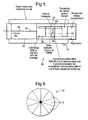
- the photovoltaic device in this example is formed from a plurality of photovoltaic cells, each of which is capable of generating power individually.
- Figure 6 shows a plane view of the photovoltaic device along the direction in which light will be incident upon the device (that is, along the axial direction with respect to figures 4 and 5 ).
- the photovoltaic device 72 is substantially circular, each cell 73 being shaped as an angular segment.
- the cells each have front and back contacts, and are connected in series, such that the front contact of one cell is connected to the back contact of an adjacent cell.
- the photovoltaic device 72 will be formed by 10 cells.
- the power source 70 is a conventional long-life battery, and the photodiode merely acts as a sensor to receive information and monitor the intensity of the incoming light from the head end.
- Figure 7 shows an embodiment of the interface unit 44 in which the identity chip 66 and the electrical storage device 70 are located within the housing 46 of the interface unit, whereas the controller stage 68 is located in the removable test device 60.
- the contract region 78 includes separate contacts 78a and 78b on the housing 46, for contacting the identity chip and the electrical storage device respectively (corresponding contacts on the removable test device being provided).
- the identity chip is of the type that is passive, that is, one that consumes substantially no power until it is interrogated by the controller stage.
- One advantage of locating the controller stage 68 in the removable test device 60 is that since the controller stage will normally includes a processor programmed in accordance with the communication protocol used to communicate with the central monitoring unit, if the communication protocol needs to be changed, a new monitoring unit 60 can simply be provided, reducing the need for the housing 46 of the interface unit to be accessed. This could be particularly advantageous for a network operator, as the network operator can simply send by mail replacement removable units to the relevant customer premises, thereby reducing the need for costly on-site visits by an engineer.
- the identity chip will preferably be an electronic semiconductor device having a permanent memory, for example a static read only memory (or ROM) formed by a plurality of gated or wired circuits, which circuits are configured according to a (preferably unique) identification data.
- a permanent memory for example a static read only memory (or ROM) formed by a plurality of gated or wired circuits, which circuits are configured according to a (preferably unique) identification data.
- the identity chip is a contactless device comprising a semiconductor device and an RF coil (either integrally formed with the semiconductor device or external thereto).
- the coil is arranged to pick up an RF electromagnetic field, which field is used to read the chip.
- the controller stage 68 and the electrical storage device are each located in the removable test device 60 rather than the interface unit 44.
- the ID chip 66 is located in the housing 46, whereas the storage device is located in the. This would allow the storage device to be replaced at the same time as the plug and keeps the cost of the housing as low as possible.
- each interface unit can be viewed as being located where the ODN terminates, indicating the demarcation point between the ODN and the customer-premises equipment.
- each interface unit will be housed within the customer premises, where a customer can easily remove the test device and connect an ONT.
- At least some of the embodiments relate to the field of optical fibre communications networks.
- future access networks such as Passive Optical Networks which provide fibre all the way between the network operator's central office and the customer's premises. It would be extremely useful to a network operator to be able to perform some basic tests such as; continuity, measure remote optical power levels, and identify network terminations automatically.
- the general concept is the use of intelligent optical network termination equipment (IONTE) at the remote periphery or network demarcation point.
- IONTE intelligent optical network termination equipment
- the IONTE could be used when normal communications services are not being supplied to the customer. It would give the network operator the ability to test the network before offering service. It might also provide a means of testing the network to the customer boundary in order to determine if it is the customer premises equipment or the operator's network that is at fault.
- electrical power is not provided directly by the access network and needs to be derived by other means.
- the fibre IONTE can act as an autonomous unit since it does not always require special test signals from the Exchange in order to perform its measurements, in contrast to systems which are designed to transmit their information only when requested.
- the IONTE can perform its measurements at random intervals and then transmit a short burst of suitably encoded data back to a centralised control system with very low probability of clashing with transmissions from other IONTEs on the same PON.
- a further aspect of at least some of the embodiments is to incorporate a permanent unique electronic identity chip within the housing of every IONTE.
- every network termination will have the capability of supplying its identity that can be read on demand either via the network itself or by a field engineer equipped with a suitable probe.
- the Intelligent Optical Network Termination Equipment (IONTE) described here is designed to work on an Access Network.
- optical infrastructure sharing networks such as Passive Optical Networks (PONs) which provide a shared fibre path between the network operator's central office and multiple customer premises.
- PONs Passive Optical Networks
- the IONTE could work independently of the optical transmission systems working over the fibre since this would give the maximum flexibility to perform future service upgrades without impacting the IONTE function.
- Figure 1 shows how the IONTE could be incorporated into a future PON network architecture.
- FIG 1 shows the IONTEs at the network demarcation points of a 256-way PON.
- the IONTEs communicate in an allocated wavelength band (such as for example the test-wavelength window around 1625nm) with a common intelligent control system. This could be located at the Exchange (Central Office) or at an intermediate location.
- a common intelligent control system such as for example the test-wavelength window around 1625nm
- WDM Wavelength Division Multiplexing
- FIG. 1 Other components shown in Figure 1 are 1:8 and 1:32 passive power splitters forming part of the Optical Distribution Network (ODN), the Optical Network Termination (ONT) equipment in the customer premises.
- ODN Optical Distribution Network
- ONT Optical Network Termination
- the IONTE should communicate over the fibre path with the common control system.
- Two means of achieving this are : (i) by employing a low-power light source such as a vertical cavity surface emitting laser (VCSEL) in the IONTE that is designed to operate in the allocated wavelength range; or (ii) by employing a centralised light source and using a reflection modulator in the IONTE.
- the second method is potentially lower power and also provides a straightforward way of proving downstream communications and synchronisation between the IONTE controller and the IONTEs.
- VCSEL vertical cavity surface emitting laser
- the first would be to use a dedicated down-stream communication channel between the controller and IONTEs to provide synchronisation; or (b) the second would be to use an asynchronous transmission technique that would either allow messages to overlap (using techniques such as code-division or frequency-division multiple access), or by reducing the probability of message collisions by using infrequent randomly timed short data bursts.
- the asynchronous solutions are preferred since they do not require a downstream receiver, and will therefore reduce power consumption at the IONTE.
- the short data burst method has the added advantage of simplicity and requires less processing power -leading to yet further reductions in power consumption.
- the optical path specification for PONs is set by international standards bodies such as the ITU (International Telecommunications Union).
- Critical parameters in PON standards are the operating wavelength plan, transmitter / receiver power levels, and reflection coefficients.
- a device placed in the optical path should not interfere with these parameters, therefore, the IONTE should use dedicated wavelengths (not employed by the PON) and introduce negligible additional loss.
- At least some of the embodiments provide a pluggable solution takes into account these requirements.
- Figure 7 shows a ONTE wall socket containing a unique line identification device (line ID) such as an electronic identity chip (similar chips are used in smart cards and animal ID tagging).
- line ID such as an electronic identity chip (similar chips are used in smart cards and animal ID tagging).
- the line ID chip consumes no power until it is interrogated by some external probe from which it draws power.
- the bare wall socket also contains a standard optical connector (possibly with dust cover) and may also contain a long-life battery such as a "coin-cell” or other energy storage device for use by an IONTE plug. It might also contain one or more of various types of energy scavenging devices such as solar cells, piezo-electric vibration transducers, etc (not shown).
- the IONTE plug shown in figure 4 is based on a standard single-mode fibre connector. It comprises connector ferrule, lens to focus light from the VCSEL onto the fibre end via a wavelength splitting filter such as a thin-film-filter (TFF) placed at an angle, and a photo-voltaic power converter or photodiode.
- TFF thin-film-filter
- the TFF allows up-stream light from the VCSEL to be wavelength multiplexed over the down-stream light from the PON.
- the IONTE plug also houses the ultra-low-power electronics and connection means to the ID chip in the IONTE socket. It might also contain a long-life battery or other power storage device.
- the basis operating principle of the IONTE plug is as follows: Downstream light from the PON is routed via the TFF to the photovoltaic power converter or photodiode - either of which can be arranged to give a measure of the amount of optical power emerging at the customers' end of the network. This power measurement could be quite coarse simply to give a go/no-go indication based on total received power, or be divided into a range of power bands, or it might even be split into wavebands to give readings for the different types of PON connected to the ODN. These measurements would then be combined with the IONTE sockets ID (and status) information for transmission back to the IONTE control system using low-duty-cycle asynchronous data bursts.
- Upstream transmission is accomplished using a VCSEL which operates in a dedicated IONTE transmission waveband.
- the upstream line code being chosen to minimise data corruption resulting from collisions and also to minimise IONTE power consumption.
- Each IONTE behaves as an autonomous unit that transmits its line ID, status, and power measurement data in short bursts at random intervals.
- the IONTE status information might include occasional updates on 'battery' voltage, housing temperature, and the result of self diagnostic checks.
- the IONTE plug might also be programmed to detect when it has been removed from its socket and for how long and then transmit this information at periodic intervals for a short period when it is reconnected. (This would allow on-demand testing by either the customer or an engineer disconnecting / reconnecting the plug.)
- the IONTE plug shown in Figure 4 is suitable for future large split PONs since it employs its own light source. However, for smaller split PONs such as the 32-way GPON systems being proposed for deployment in 2008, a simple reflection modulator could be used as shown in the plug design in Figure 5 .
- Figure 5 shows a plug employing a surface reflection modulator such as a ferro-electric liquid crystal cell followed by reflection filter. This would result in polarisation modulation that could be converted to intensity modulation at the central controller.
- a wide range of alternative surface modulator technologies could be used with equal effect and low power consumption. Apart from this, the operating principle is identical to that described previously. However, as this scheme inherently requires a centralised light source, it would be straightforward to incorporate synchronisation information and allow each IONTE to be addressed on demand.
- the PV converter which is arranged to perform two functions: (i) to give a measure of ⁇ ZxAX amount of optical power emerging at the customers' end of the network; and (ii) to develop sufficient voltage 'V' and time-averaged current 'I_ave' to drive the IONTE electronics.
- the current demanded by the electronics will vary with time, being highest for the short periods when the laser is being driven with the burst-mode transmissions.
- the time averaged power (V x I_ave) delivered by the photovoltaic converter should be equal to or larger than the time averaged power required by the electronics (including laser).
- the PV power converter shown in Figure 6 is based on 10 serially connected photodiodes arranged in a 'pie-like' structure in order to give near uniform illumination, hence photocurrent, in each section when light from the end of the PON is imaged onto it.
- the PV is designed for operation in the down-stream wavelength bands used on PONs.
- PV Device parameters, suitable for a PON operating ⁇ 1.5um with output light levels of ⁇ 16uW (or -18dBm) are listed in the Table 1.
- Ultra-low-power electronics with operating voltages of 1.8v or lower and quiescent (or sleep-mode) current consumption well below 1 uA are known -see for example: Texas Instruments MSP430 micro-controller family; and Amtel's picoPower technology.
- some aspects of the embodiments relate to: exploiting the unused light emerging from the end of a fibre network such as a PON to provide power to electronic equipment used to provide network status information; using a multi-cell photovoltaic converter based on a pie-structure and using an annular focusing arrangement to avoid power-wastage in the central dead-spot; using the same photovoltaic converter to measure the received optical power level for diagnostic testing purposes as part of a self powered IONTE; realising that low-power photovoltaic converters, connected to power storage devices, are capable of powering emergent ultra-low-power electronic processing and low-power laser sources such as VCSELs for applications in self-powered optical network termination equipment.
- At least one of the above embodiments can be described as relating to the testing a passive optical network having a head end and a plurality of terminals, which terminals are connected to the network at a respective plug and socket arrangement located at customer premises.
- a test device is provided having a standard plug for connection in place of a terminal in the socket of the relevant customer premises.
- An identification device is provided in the socket. The test device is arranged to (i) read the identity of the identification device and (ii) test the line and transmit a result to the head end together with the identity so that the line to the customer premises can be tested remotely. When the line has been tested, the test device can be removed. Because the test device uses an existing connection, the optical (insertion) loss is reduced.
Landscapes
- Physics & Mathematics (AREA)
- Electromagnetism (AREA)
- Engineering & Computer Science (AREA)
- Computer Networks & Wireless Communication (AREA)
- Signal Processing (AREA)
- Optical Communication System (AREA)
Claims (14)
- Système de test ayant un appareil connecteur (44) comprenant une prise (52), pour connecter, de manière libérable, un réseau optique à une unité terminale (14), l'appareil connecteur ayant un identifiant lui étant associé, et un circuit d'identifiant pour délivrer un signal d'identification, lequel signal d'identification est indicatif de l'identifiant associé à l'appareil connecteur ; caractérisé en ce que le système comprend en outre un dispositif de test (60) comprenant une partie fiche (62), qui est connectable de manière libérable à l'appareil connecteur en branchant dans la prise de l'appareil connecteur, le dispositif de test étant opérationnel en utilisation avec l'appareil connecteur pour mesurer au moins une caractéristique d'un signal optique du réseau optique, et pour transmettre un signal de test, lequel signal de test comprend une indication de la/des caractéristique(s) mesurée(s) et une indication de l'identifiant associé à l'appareil connecteur.
- Système de test tel que revendiqué dans la revendication 1, dans lequel la ou une caractéristique mesurée est une indication de la puissance optique du signal optique du réseau optique.
- Système de test tel que revendiqué dans la revendication 1 ou la revendication 2, dans lequel l'appareil connecteur a une région de connecteur (52) commune pour se connecter, de manière interchangeable, à un élément parmi une unité terminale et le dispositif de surveillance.
- Système de test tel que revendiqué dans l'une quelconque des revendications précédentes, dans lequel le dispositif de test a un circuit électronique (68) pour coder le signal de test.
- Système de test tel que revendiqué dans l'une quelconque des revendications précédentes, dans lequel l'appareil connecteur comprend un boîtier mural.
- Système de test tel que revendiqué dans l'une quelconque des revendications précédentes, dans lequel l'appareil connecteur (44) a un premier connecteur dans une première configuration arrangé pour s'engager, de manière libérable, avec un connecteur coopérant dans une seconde configuration, et où chacun de l'unité terminale (14) et du dispositif de test (60) a un connecteur arrangé conformément à la seconde configuration.
- Système de test tel que revendiqué selon l'une quelconque des revendications précédentes, dans lequel les connecteurs situés dans les première et seconde configurations sont arrangés de manière à former une connexion optique.
- Système de test tel que revendiqué selon l'une quelconque des revendications précédentes, dans lequel le système de test est conçu pour transmettre des signaux de test à intervalles aléatoires.
- Système de communication comprenant : un système de test tel que revendiqué dans la revendication 6 ou la revendication 8 ; et une unité terminale (14), l'unité terminale ayant un connecteur arrangé conformément à la seconde configuration.
- Système de communication tel que revendiqué dans l'une quelconque des revendications 6 à 9, dans lequel le système de communication a : un état opérationnel dans lequel l'unité terminale est connectée au premier connecteur ; et, un état de test dans lequel l'unité terminale est retirée du premier connecteur et le dispositif de test est connecté au premier connecteur à la place de l'unité terminale.
- Système de communication tel que revendiqué dans l'une quelconque des revendications 6 à 10, dans lequel le terminal est conçu pour transmettre des données en salves conformément à une instruction d'ordonnancement.
- Réseau de communication comprenant une pluralité de systèmes de test tels que revendiqué dans l'une quelconque des revendications 1 à 6, dans lequel le réseau de communication comprend le réseau optique, et où le réseau optique est conçu pour diffuser des signaux optiques à chacun des systèmes de test.
- Procédé pour utiliser un système de test comprenant :un procédé de test d'un réseau optique conçu pour diffuser des signaux optiques vers une pluralité de dispositifs de connecteur réseau, comprenant les étapes suivantes : recevoir un signal optique au niveau d'un dispositif connecteur ; mesurer une ou plusieurs caractéristiques du signal optique au moyen d'un dispositif de test ; et, convertir une puissance optique dans le signal optique en puissance électrique ; et alimenter en puissance le dispositif de test avec la puissance optique convertie ;fournir un appareil connecteur pour connecter, de manière libérable, un réseau optique à une unité terminale, l'appareil connecteur ayant un identifiant lui étant associé, et un circuit d'identifiant pour délivrer un signal d'identification, lequel signal d'identification est indicatif de l'identifiant associé à l'appareil connecteur ;fournir un dispositif de test qui est connectable, de manière libérable, à l'appareil connecteur, le dispositif de test étant opérationnel utilisé avec l'appareil connecteur pour mesurer au moins une caractéristique d'un signal optique du réseau optique, et pour transmettre un signal de test, lequel signal de test comprend une indication de la/des caractéristique(s) mesurée(s) et une indication de l'identifiant associé à l'appareil connecteur ; etbrancher le dispositif de test dans une prise de l'appareil connecteur.
- Procédé selon la revendication 13, comprenant le retrait d'une fiche d'une unité terminale de la prise de l'appareil connecteur antérieurement au branchement du dispositif de test dans la prise de l'appareil connecteur.
Priority Applications (1)
| Application Number | Priority Date | Filing Date | Title |
|---|---|---|---|
| EP08709524.6A EP2119060B1 (fr) | 2007-02-28 | 2008-02-26 | Contrôle d'un réseau optique |
Applications Claiming Priority (3)
| Application Number | Priority Date | Filing Date | Title |
|---|---|---|---|
| EP07250847A EP1965517A1 (fr) | 2007-02-28 | 2007-02-28 | Test d'un réseau optique |
| EP08709524.6A EP2119060B1 (fr) | 2007-02-28 | 2008-02-26 | Contrôle d'un réseau optique |
| PCT/GB2008/000644 WO2008104759A1 (fr) | 2007-02-28 | 2008-02-26 | Contrôle d'un réseau optique |
Publications (2)
| Publication Number | Publication Date |
|---|---|
| EP2119060A1 EP2119060A1 (fr) | 2009-11-18 |
| EP2119060B1 true EP2119060B1 (fr) | 2014-03-12 |
Family
ID=38261645
Family Applications (2)
| Application Number | Title | Priority Date | Filing Date |
|---|---|---|---|
| EP07250847A Withdrawn EP1965517A1 (fr) | 2007-02-28 | 2007-02-28 | Test d'un réseau optique |
| EP08709524.6A Active EP2119060B1 (fr) | 2007-02-28 | 2008-02-26 | Contrôle d'un réseau optique |
Family Applications Before (1)
| Application Number | Title | Priority Date | Filing Date |
|---|---|---|---|
| EP07250847A Withdrawn EP1965517A1 (fr) | 2007-02-28 | 2007-02-28 | Test d'un réseau optique |
Country Status (3)
| Country | Link |
|---|---|
| US (1) | US8452172B2 (fr) |
| EP (2) | EP1965517A1 (fr) |
| WO (1) | WO2008104759A1 (fr) |
Families Citing this family (14)
| Publication number | Priority date | Publication date | Assignee | Title |
|---|---|---|---|---|
| US9276673B2 (en) * | 2008-04-24 | 2016-03-01 | Commscope Technologies Llc | Methods and systems for testing a fiber optic network |
| CN110082844A (zh) | 2009-02-09 | 2019-08-02 | 艾克斯瑟乐普林特有限公司 | 集中器型光电(cpv)模块、接收器和子接收器及其形成方法 |
| US20110200284A1 (en) * | 2009-06-12 | 2011-08-18 | Igor Zhovnirovsky | Fiber Optic Jack with High Interface Mismatch Tolerance |
| US8766165B1 (en) | 2009-06-12 | 2014-07-01 | Applied Micro Circuits Corporation | Pattern-based optical lens testing apparatus having a module comparing a viewed image representation to a copy of target pattern and method for using the same |
| EP2388955B1 (fr) * | 2010-05-20 | 2014-03-12 | Alcatel Lucent | Procédé et appareils pour supporter des fonctions de réseau dans un réseau optique passif |
| JP2013061481A (ja) * | 2011-09-13 | 2013-04-04 | Fujitsu Ltd | 光通信モジュール及び光通信装置 |
| US9088357B2 (en) | 2012-09-28 | 2015-07-21 | Applied Micro Circuits Corporation | Imaging system for passive alignment of engines |
| EP3373480A1 (fr) * | 2013-08-07 | 2018-09-12 | Viavi Solutions Deutschland GmbH | Test d'un réseau optique passif |
| EP3039847B1 (fr) * | 2013-08-28 | 2018-06-20 | Telefonaktiebolaget LM Ericsson (publ) | Configuration, système et procédés dans celle-ci pour surveiller une ligne de transmission |
| US9673897B2 (en) | 2015-06-30 | 2017-06-06 | Viavi Solutions Deutschland Gmbh | Optical network test instrument including optical network unit identifier capture capability from downstream signals |
| WO2017059079A1 (fr) * | 2015-09-29 | 2017-04-06 | Semprius, Inc. | Dispositifs miniaturisés pour transmission de données et conversion de puissance optique combinées |
| WO2017105581A2 (fr) | 2015-10-02 | 2017-06-22 | Semprius, Inc. | Éléments photovoltaïques concentrés (cpv) de très petites dimensions à tranches intégrées pour applications spatiales |
| US11528079B2 (en) * | 2017-10-05 | 2022-12-13 | Commscope Technologies Llc | Optical fiber testing device and method |
| US11178472B2 (en) * | 2018-06-08 | 2021-11-16 | Nokia Solutions And Networks Oy | Monitoring multiple passive optical networks |
Family Cites Families (10)
| Publication number | Priority date | Publication date | Assignee | Title |
|---|---|---|---|---|
| US4278850A (en) * | 1978-04-11 | 1981-07-14 | Kokusai Denshin Denwa Co., Ltd. | Monitoring system for optical transmission line repeaters |
| ES2139033T3 (es) * | 1993-05-10 | 2000-02-01 | Sumitomo Electric Industries | Aparato y procedimiento para conmutar lineas de transmision optica. |
| US6418195B1 (en) * | 1999-12-30 | 2002-07-09 | Marconi Communications, Inc. | Apparatus for communicating a diagnostic device with a telecommunications system through a remote network unit |
| JP2002202441A (ja) * | 2000-11-02 | 2002-07-19 | Nippon Telegr & Teleph Corp <Ntt> | Lan用光アクティブコネクタプラグ及びコネクタポート |
| US20030021580A1 (en) * | 2001-07-18 | 2003-01-30 | Photoris, Inc. | Method and apparatus for coupling terminal equipment to a node in an optical communications network |
| US7203420B1 (en) * | 2002-03-28 | 2007-04-10 | Bellsouth Intellectual Property Corporation | DCC loop plug |
| US7468958B2 (en) * | 2005-05-06 | 2008-12-23 | Tellabs Petaluma, Inc. | Optical line terminal that detects and identifies a rogue ONT |
| US7234880B1 (en) * | 2006-01-09 | 2007-06-26 | Acterna L.L.C. | Internal pluggable optical module |
| US20070242954A1 (en) * | 2006-04-14 | 2007-10-18 | Tellabs Petaluma, Inc. | System and method for monitoring transmissions within a passive optical network |
| US7772975B2 (en) * | 2006-10-31 | 2010-08-10 | Corning Cable Systems, Llc | System for mapping connections using RFID function |
-
2007
- 2007-02-28 EP EP07250847A patent/EP1965517A1/fr not_active Withdrawn
-
2008
- 2008-02-26 EP EP08709524.6A patent/EP2119060B1/fr active Active
- 2008-02-26 WO PCT/GB2008/000644 patent/WO2008104759A1/fr active Application Filing
- 2008-02-26 US US12/527,819 patent/US8452172B2/en active Active
Also Published As
| Publication number | Publication date |
|---|---|
| EP1965517A1 (fr) | 2008-09-03 |
| US8452172B2 (en) | 2013-05-28 |
| EP2119060A1 (fr) | 2009-11-18 |
| US20100014854A1 (en) | 2010-01-21 |
| WO2008104759A1 (fr) | 2008-09-04 |
Similar Documents
| Publication | Publication Date | Title |
|---|---|---|
| EP2119060B1 (fr) | Contrôle d'un réseau optique | |
| CN102714545B (zh) | 光收发模块、无源光网络系统、光纤检测方法和系统 | |
| CN102971974B (zh) | 单纤双向光模块及无源光网络系统 | |
| CN102130720B (zh) | 无源光网络的光功率检测方法、系统和装置 | |
| RU2564100C2 (ru) | Оптическая сетевая система связи с приемопередающим устройством оптического линейного терминала и способ ее работы | |
| US20120288273A1 (en) | Intelligent splitter monitor | |
| EP3134986B1 (fr) | Appareil et système pour gérer des longueurs d'onde dans des réseaux optiques | |
| US8543001B2 (en) | Cascaded injection locking of fabry-perot laser for wave division multiplexing passive optical networks | |
| US9118982B2 (en) | Optical line terminal (OLT) optical module adapted to perform optical unit network (ONU) functionality | |
| EP1986350B1 (fr) | Unité de surveillance, réseau optique et procédé d'exploitation pour le réseau optique | |
| CN101540937A (zh) | 无源光网络的监测方法 | |
| CN100440756C (zh) | 一种无源光网络及其数据通信的方法 | |
| CN202334536U (zh) | 光收发组件和采用该光收发组件的无源光网络系统及设备 | |
| CN101436902B (zh) | 一种光网络单元 | |
| CN105451840A (zh) | 一种光时域反射仪实现装置及系统 | |
| CN106506069B (zh) | 光线路终端、光收发模块、系统以及光纤检测方法 | |
| US8340519B2 (en) | Passive optical network comprising an optical burst mode receiver | |
| Hehmann et al. | Remotely powered intelligent splitter monitor for fiber access networks | |
| EP1965516A1 (fr) | Alimentation optique | |
| EP2015371A1 (fr) | Conversion d'énergie optique | |
| Hehmann et al. | New monitoring concepts for optical access networks | |
| CN203761404U (zh) | 采用以太网无光源网络的光模块 | |
| KR100869906B1 (ko) | 기가급 밀집형 파장분할다중화방식 수동광가입자망의 복합광네트워크장치 및 그 복합 광네크워크장치를 위한정합모듈 | |
| CN102281101B (zh) | 突发模式发射光功率实时监测和保持的方法和装置 | |
| CN114337806A (zh) | 一种光功率检测方法、装置及光网络终端 |
Legal Events
| Date | Code | Title | Description |
|---|---|---|---|
| PUAI | Public reference made under article 153(3) epc to a published international application that has entered the european phase |
Free format text: ORIGINAL CODE: 0009012 |
|
| 17P | Request for examination filed |
Effective date: 20090817 |
|
| AK | Designated contracting states |
Kind code of ref document: A1 Designated state(s): AT BE BG CH CY CZ DE DK EE ES FI FR GB GR HR HU IE IS IT LI LT LU LV MC MT NL NO PL PT RO SE SI SK TR |
|
| 17Q | First examination report despatched |
Effective date: 20091221 |
|
| DAX | Request for extension of the european patent (deleted) | ||
| REG | Reference to a national code |
Ref country code: DE Ref legal event code: R079 Ref document number: 602008030794 Country of ref document: DE Free format text: PREVIOUS MAIN CLASS: H04B0010080000 Ipc: H04B0010077000 |
|
| GRAP | Despatch of communication of intention to grant a patent |
Free format text: ORIGINAL CODE: EPIDOSNIGR1 |
|
| RIC1 | Information provided on ipc code assigned before grant |
Ipc: H04B 10/079 20130101ALI20130829BHEP Ipc: H04B 10/80 20130101ALI20130829BHEP Ipc: H04B 10/077 20130101AFI20130829BHEP |
|
| INTG | Intention to grant announced |
Effective date: 20130920 |
|
| GRAS | Grant fee paid |
Free format text: ORIGINAL CODE: EPIDOSNIGR3 |
|
| GRAA | (expected) grant |
Free format text: ORIGINAL CODE: 0009210 |
|
| AK | Designated contracting states |
Kind code of ref document: B1 Designated state(s): AT BE BG CH CY CZ DE DK EE ES FI FR GB GR HR HU IE IS IT LI LT LU LV MC MT NL NO PL PT RO SE SI SK TR |
|
| REG | Reference to a national code |
Ref country code: GB Ref legal event code: FG4D |
|
| REG | Reference to a national code |
Ref country code: CH Ref legal event code: EP |
|
| REG | Reference to a national code |
Ref country code: AT Ref legal event code: REF Ref document number: 656888 Country of ref document: AT Kind code of ref document: T Effective date: 20140315 |
|
| REG | Reference to a national code |
Ref country code: IE Ref legal event code: FG4D |
|
| REG | Reference to a national code |
Ref country code: DE Ref legal event code: R096 Ref document number: 602008030794 Country of ref document: DE Effective date: 20140424 |
|
| REG | Reference to a national code |
Ref country code: NL Ref legal event code: VDEP Effective date: 20140312 |
|
| PG25 | Lapsed in a contracting state [announced via postgrant information from national office to epo] |
Ref country code: NO Free format text: LAPSE BECAUSE OF FAILURE TO SUBMIT A TRANSLATION OF THE DESCRIPTION OR TO PAY THE FEE WITHIN THE PRESCRIBED TIME-LIMIT Effective date: 20140612 Ref country code: LT Free format text: LAPSE BECAUSE OF FAILURE TO SUBMIT A TRANSLATION OF THE DESCRIPTION OR TO PAY THE FEE WITHIN THE PRESCRIBED TIME-LIMIT Effective date: 20140312 |
|
| REG | Reference to a national code |
Ref country code: AT Ref legal event code: MK05 Ref document number: 656888 Country of ref document: AT Kind code of ref document: T Effective date: 20140312 |
|
| REG | Reference to a national code |
Ref country code: LT Ref legal event code: MG4D |
|
| PG25 | Lapsed in a contracting state [announced via postgrant information from national office to epo] |
Ref country code: CY Free format text: LAPSE BECAUSE OF FAILURE TO SUBMIT A TRANSLATION OF THE DESCRIPTION OR TO PAY THE FEE WITHIN THE PRESCRIBED TIME-LIMIT Effective date: 20140312 Ref country code: FI Free format text: LAPSE BECAUSE OF FAILURE TO SUBMIT A TRANSLATION OF THE DESCRIPTION OR TO PAY THE FEE WITHIN THE PRESCRIBED TIME-LIMIT Effective date: 20140312 Ref country code: SE Free format text: LAPSE BECAUSE OF FAILURE TO SUBMIT A TRANSLATION OF THE DESCRIPTION OR TO PAY THE FEE WITHIN THE PRESCRIBED TIME-LIMIT Effective date: 20140312 |
|
| PG25 | Lapsed in a contracting state [announced via postgrant information from national office to epo] |
Ref country code: LV Free format text: LAPSE BECAUSE OF FAILURE TO SUBMIT A TRANSLATION OF THE DESCRIPTION OR TO PAY THE FEE WITHIN THE PRESCRIBED TIME-LIMIT Effective date: 20140312 Ref country code: HR Free format text: LAPSE BECAUSE OF FAILURE TO SUBMIT A TRANSLATION OF THE DESCRIPTION OR TO PAY THE FEE WITHIN THE PRESCRIBED TIME-LIMIT Effective date: 20140312 |
|
| PG25 | Lapsed in a contracting state [announced via postgrant information from national office to epo] |
Ref country code: CZ Free format text: LAPSE BECAUSE OF FAILURE TO SUBMIT A TRANSLATION OF THE DESCRIPTION OR TO PAY THE FEE WITHIN THE PRESCRIBED TIME-LIMIT Effective date: 20140312 Ref country code: NL Free format text: LAPSE BECAUSE OF FAILURE TO SUBMIT A TRANSLATION OF THE DESCRIPTION OR TO PAY THE FEE WITHIN THE PRESCRIBED TIME-LIMIT Effective date: 20140312 Ref country code: IS Free format text: LAPSE BECAUSE OF FAILURE TO SUBMIT A TRANSLATION OF THE DESCRIPTION OR TO PAY THE FEE WITHIN THE PRESCRIBED TIME-LIMIT Effective date: 20140712 Ref country code: EE Free format text: LAPSE BECAUSE OF FAILURE TO SUBMIT A TRANSLATION OF THE DESCRIPTION OR TO PAY THE FEE WITHIN THE PRESCRIBED TIME-LIMIT Effective date: 20140312 Ref country code: RO Free format text: LAPSE BECAUSE OF FAILURE TO SUBMIT A TRANSLATION OF THE DESCRIPTION OR TO PAY THE FEE WITHIN THE PRESCRIBED TIME-LIMIT Effective date: 20140312 Ref country code: BG Free format text: LAPSE BECAUSE OF FAILURE TO SUBMIT A TRANSLATION OF THE DESCRIPTION OR TO PAY THE FEE WITHIN THE PRESCRIBED TIME-LIMIT Effective date: 20140612 Ref country code: BE Free format text: LAPSE BECAUSE OF FAILURE TO SUBMIT A TRANSLATION OF THE DESCRIPTION OR TO PAY THE FEE WITHIN THE PRESCRIBED TIME-LIMIT Effective date: 20140312 |
|
| PG25 | Lapsed in a contracting state [announced via postgrant information from national office to epo] |
Ref country code: ES Free format text: LAPSE BECAUSE OF FAILURE TO SUBMIT A TRANSLATION OF THE DESCRIPTION OR TO PAY THE FEE WITHIN THE PRESCRIBED TIME-LIMIT Effective date: 20140312 Ref country code: AT Free format text: LAPSE BECAUSE OF FAILURE TO SUBMIT A TRANSLATION OF THE DESCRIPTION OR TO PAY THE FEE WITHIN THE PRESCRIBED TIME-LIMIT Effective date: 20140312 Ref country code: PL Free format text: LAPSE BECAUSE OF FAILURE TO SUBMIT A TRANSLATION OF THE DESCRIPTION OR TO PAY THE FEE WITHIN THE PRESCRIBED TIME-LIMIT Effective date: 20140312 Ref country code: SK Free format text: LAPSE BECAUSE OF FAILURE TO SUBMIT A TRANSLATION OF THE DESCRIPTION OR TO PAY THE FEE WITHIN THE PRESCRIBED TIME-LIMIT Effective date: 20140312 |
|
| REG | Reference to a national code |
Ref country code: DE Ref legal event code: R097 Ref document number: 602008030794 Country of ref document: DE |
|
| PG25 | Lapsed in a contracting state [announced via postgrant information from national office to epo] |
Ref country code: PT Free format text: LAPSE BECAUSE OF FAILURE TO SUBMIT A TRANSLATION OF THE DESCRIPTION OR TO PAY THE FEE WITHIN THE PRESCRIBED TIME-LIMIT Effective date: 20140714 |
|
| PLBE | No opposition filed within time limit |
Free format text: ORIGINAL CODE: 0009261 |
|
| STAA | Information on the status of an ep patent application or granted ep patent |
Free format text: STATUS: NO OPPOSITION FILED WITHIN TIME LIMIT |
|
| PG25 | Lapsed in a contracting state [announced via postgrant information from national office to epo] |
Ref country code: DK Free format text: LAPSE BECAUSE OF FAILURE TO SUBMIT A TRANSLATION OF THE DESCRIPTION OR TO PAY THE FEE WITHIN THE PRESCRIBED TIME-LIMIT Effective date: 20140312 |
|
| 26N | No opposition filed |
Effective date: 20141215 |
|
| REG | Reference to a national code |
Ref country code: DE Ref legal event code: R097 Ref document number: 602008030794 Country of ref document: DE Effective date: 20141215 |
|
| PG25 | Lapsed in a contracting state [announced via postgrant information from national office to epo] |
Ref country code: IT Free format text: LAPSE BECAUSE OF FAILURE TO SUBMIT A TRANSLATION OF THE DESCRIPTION OR TO PAY THE FEE WITHIN THE PRESCRIBED TIME-LIMIT Effective date: 20140312 |
|
| PG25 | Lapsed in a contracting state [announced via postgrant information from national office to epo] |
Ref country code: SI Free format text: LAPSE BECAUSE OF FAILURE TO SUBMIT A TRANSLATION OF THE DESCRIPTION OR TO PAY THE FEE WITHIN THE PRESCRIBED TIME-LIMIT Effective date: 20140312 |
|
| PG25 | Lapsed in a contracting state [announced via postgrant information from national office to epo] |
Ref country code: LU Free format text: LAPSE BECAUSE OF FAILURE TO SUBMIT A TRANSLATION OF THE DESCRIPTION OR TO PAY THE FEE WITHIN THE PRESCRIBED TIME-LIMIT Effective date: 20150226 |
|
| REG | Reference to a national code |
Ref country code: CH Ref legal event code: PL |
|
| PG25 | Lapsed in a contracting state [announced via postgrant information from national office to epo] |
Ref country code: CH Free format text: LAPSE BECAUSE OF NON-PAYMENT OF DUE FEES Effective date: 20150228 Ref country code: LI Free format text: LAPSE BECAUSE OF NON-PAYMENT OF DUE FEES Effective date: 20150228 Ref country code: MC Free format text: LAPSE BECAUSE OF FAILURE TO SUBMIT A TRANSLATION OF THE DESCRIPTION OR TO PAY THE FEE WITHIN THE PRESCRIBED TIME-LIMIT Effective date: 20140312 |
|
| REG | Reference to a national code |
Ref country code: IE Ref legal event code: MM4A |
|
| PG25 | Lapsed in a contracting state [announced via postgrant information from national office to epo] |
Ref country code: IE Free format text: LAPSE BECAUSE OF NON-PAYMENT OF DUE FEES Effective date: 20150226 |
|
| REG | Reference to a national code |
Ref country code: FR Ref legal event code: PLFP Year of fee payment: 9 |
|
| PG25 | Lapsed in a contracting state [announced via postgrant information from national office to epo] |
Ref country code: GR Free format text: LAPSE BECAUSE OF FAILURE TO SUBMIT A TRANSLATION OF THE DESCRIPTION OR TO PAY THE FEE WITHIN THE PRESCRIBED TIME-LIMIT Effective date: 20140613 |
|
| PG25 | Lapsed in a contracting state [announced via postgrant information from national office to epo] |
Ref country code: MT Free format text: LAPSE BECAUSE OF FAILURE TO SUBMIT A TRANSLATION OF THE DESCRIPTION OR TO PAY THE FEE WITHIN THE PRESCRIBED TIME-LIMIT Effective date: 20140312 |
|
| REG | Reference to a national code |
Ref country code: FR Ref legal event code: PLFP Year of fee payment: 10 |
|
| PG25 | Lapsed in a contracting state [announced via postgrant information from national office to epo] |
Ref country code: HU Free format text: LAPSE BECAUSE OF FAILURE TO SUBMIT A TRANSLATION OF THE DESCRIPTION OR TO PAY THE FEE WITHIN THE PRESCRIBED TIME-LIMIT; INVALID AB INITIO Effective date: 20080226 |
|
| PG25 | Lapsed in a contracting state [announced via postgrant information from national office to epo] |
Ref country code: TR Free format text: LAPSE BECAUSE OF FAILURE TO SUBMIT A TRANSLATION OF THE DESCRIPTION OR TO PAY THE FEE WITHIN THE PRESCRIBED TIME-LIMIT Effective date: 20140312 |
|
| REG | Reference to a national code |
Ref country code: FR Ref legal event code: PLFP Year of fee payment: 11 |
|
| PGFP | Annual fee paid to national office [announced via postgrant information from national office to epo] |
Ref country code: FR Payment date: 20230119 Year of fee payment: 16 |
|
| P01 | Opt-out of the competence of the unified patent court (upc) registered |
Effective date: 20230623 |
|
| PGFP | Annual fee paid to national office [announced via postgrant information from national office to epo] |
Ref country code: DE Payment date: 20240123 Year of fee payment: 17 Ref country code: GB Payment date: 20240123 Year of fee payment: 17 |