EP2118968B1 - Electrical terminal block and method of fixture - Google Patents
Electrical terminal block and method of fixture Download PDFInfo
- Publication number
- EP2118968B1 EP2118968B1 EP08709495A EP08709495A EP2118968B1 EP 2118968 B1 EP2118968 B1 EP 2118968B1 EP 08709495 A EP08709495 A EP 08709495A EP 08709495 A EP08709495 A EP 08709495A EP 2118968 B1 EP2118968 B1 EP 2118968B1
- Authority
- EP
- European Patent Office
- Prior art keywords
- block
- undersurface
- lugs
- edges
- electrical terminal
- Prior art date
- Legal status (The legal status is an assumption and is not a legal conclusion. Google has not performed a legal analysis and makes no representation as to the accuracy of the status listed.)
- Not-in-force
Links
Images


Classifications
-
- H—ELECTRICITY
- H01—ELECTRIC ELEMENTS
- H01R—ELECTRICALLY-CONDUCTIVE CONNECTIONS; STRUCTURAL ASSOCIATIONS OF A PLURALITY OF MUTUALLY-INSULATED ELECTRICAL CONNECTING ELEMENTS; COUPLING DEVICES; CURRENT COLLECTORS
- H01R9/00—Structural associations of a plurality of mutually-insulated electrical connecting elements, e.g. terminal strips or terminal blocks; Terminals or binding posts mounted upon a base or in a case; Bases therefor
- H01R9/22—Bases, e.g. strip, block, panel
- H01R9/24—Terminal blocks
- H01R9/26—Clip-on terminal blocks for side-by-side rail- or strip-mounting
- H01R9/2608—Fastening means for mounting on support rail or strip
-
- H—ELECTRICITY
- H01—ELECTRIC ELEMENTS
- H01R—ELECTRICALLY-CONDUCTIVE CONNECTIONS; STRUCTURAL ASSOCIATIONS OF A PLURALITY OF MUTUALLY-INSULATED ELECTRICAL CONNECTING ELEMENTS; COUPLING DEVICES; CURRENT COLLECTORS
- H01R13/00—Details of coupling devices of the kinds covered by groups H01R12/70 or H01R24/00 - H01R33/00
- H01R13/66—Structural association with built-in electrical component
- H01R13/717—Structural association with built-in electrical component with built-in light source
- H01R13/7172—Conduits for light transmission
-
- H—ELECTRICITY
- H01—ELECTRIC ELEMENTS
- H01R—ELECTRICALLY-CONDUCTIVE CONNECTIONS; STRUCTURAL ASSOCIATIONS OF A PLURALITY OF MUTUALLY-INSULATED ELECTRICAL CONNECTING ELEMENTS; COUPLING DEVICES; CURRENT COLLECTORS
- H01R13/00—Details of coupling devices of the kinds covered by groups H01R12/70 or H01R24/00 - H01R33/00
- H01R13/66—Structural association with built-in electrical component
- H01R13/717—Structural association with built-in electrical component with built-in light source
- H01R13/7175—Light emitting diodes (LEDs)
-
- H—ELECTRICITY
- H01—ELECTRIC ELEMENTS
- H01R—ELECTRICALLY-CONDUCTIVE CONNECTIONS; STRUCTURAL ASSOCIATIONS OF A PLURALITY OF MUTUALLY-INSULATED ELECTRICAL CONNECTING ELEMENTS; COUPLING DEVICES; CURRENT COLLECTORS
- H01R9/00—Structural associations of a plurality of mutually-insulated electrical connecting elements, e.g. terminal strips or terminal blocks; Terminals or binding posts mounted upon a base or in a case; Bases therefor
- H01R9/22—Bases, e.g. strip, block, panel
- H01R9/24—Terminal blocks
- H01R9/26—Clip-on terminal blocks for side-by-side rail- or strip-mounting
- H01R9/2625—Clip-on terminal blocks for side-by-side rail- or strip-mounting with built-in electrical component
- H01R9/2633—Clip-on terminal blocks for side-by-side rail- or strip-mounting with built-in electrical component with built-in switch
-
- H—ELECTRICITY
- H02—GENERATION; CONVERSION OR DISTRIBUTION OF ELECTRIC POWER
- H02G—INSTALLATION OF ELECTRIC CABLES OR LINES, OR OF COMBINED OPTICAL AND ELECTRIC CABLES OR LINES
- H02G3/00—Installations of electric cables or lines or protective tubing therefor in or on buildings, equivalent structures or vehicles
- H02G3/02—Details
- H02G3/08—Distribution boxes; Connection or junction boxes
- H02G3/16—Distribution boxes; Connection or junction boxes structurally associated with support for line-connecting terminals within the box
Definitions
- This invention relates to an electrical terminal block and to a method of fixing an electrical terminal block to a fixed support.
- the purpose of the present invention is to simplify the way in which an electrical terminal block may be attached to a fixture such as a DIN rail.
- DE1183567B discloses an electrical device whose base has four or more lugs projecting downwardly from a generally flat undersurface for locking the block against a fixed support having edges which are co-planar in a plane parallel to the block's undersurface, at least two of the lugs being formed with opposed channels, each open at one side for receiving and laterally abutting against one of two corresponding oppositely-extending edges of the fixed support so as to lock the block against the support, at least two others of the lugs being stops for laterally abutting corresponding edges of the fixed support, whereby the block may be fixed to the support by resting its undersurface against the block and twisting it in the plane of the undersurface until all the lugs are in abutment against the corresponding edges.
- the present invention provides an electrical terminal block whose base has eight or more lugs projecting downwardly from a generally flat undersurface for locking the block against a fixed support having edges which are co-planar in a plane parallel to the block's undersurface; at least four of the lugs being formed with opposed channels, each open at one side for receiving and laterally abutting against one of two corresponding oppositely-extending edges of the fixed support so as to lock the block against the support, at least four others of the lugs being stops for laterally abutting corresponding edges of the fixed support; in which each stop lug is resiliently moveable upwardly, normal to the undersurface, when depressed, to reduce the extent of its projection from the undersurface; and in which each channelled lug is aligned with a stop lug along a different side of a quadrilateral; whereby the block may be fixed to the support by resting its undersurface against the block and twisting it in the plane of the undersurface until all the lugs are in abutment against the corresponding edges.
- Electrical terminal blocks embodying the invention may be manufactured relatively inexpensively. Further, the twist and snap fit action in the preferred embodiment facilitates the fixture of the block on to a DIN rail, for example. In the preferred embodiment, the block is removable from the fixture by reversing the twist process, and this allows it to be repositioned or replaced.
- electrical or electronic circuitry may be connected to different terminals, such as sprung terminals which mate with external terminals, as well as, or instead of, the terminals 14 shown.
- electronic circuitry may be integrated in the electrical terminal block 10. Examples of electronic circuitry to which the invention may be applied include relays and other forms of switch and communications circuitry.
- the terminal block 10 may be removably fixed to a DIN rail 30 as shown in Figure 5 , by means of an arrangement of lugs 18, 19 projecting downwardly from the otherwise flat undersurface of the block.
- lugs 18, 19 projecting downwardly from the otherwise flat undersurface of the block.
- Each stop lug 19a to 19d projects from a tongue 20a to 20d forming part of a base plate of the terminal block 10, and resiliently deformable upwardly to allow the outer facing surface of the stop lug to be coplanar with the undersurface of the block.
- the wedge shaped stop lug 19a to 19d projects from the undersurface plane a distance which corresponds to the depth of a channel 21a to 21d formed in each of the channelled lugs 18a to 18d.
- the channel of each channelled lug is defined by a re-entrant surface which faces the planar undersurface of the block.
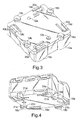
- the base plate of the block has semicircular portions of which two are illustrated as 22a, 22c in Figure 4 , and these accommodate the channelled lugs 18a to 18d with an air gap.
- each stop lug 19a to 19d is elongate along the edge of the block, and its outward surface is inclined so that it is thicker the closer it gets to its corresponding channelled lug on the same edge of the block.
- this shape of wedge is convenient for facilitating separation of the block from a DIN rail, as described below, its shape is not critical, and the wedge shape is not essential.
- the block 10 may be fixed to a DIN rail 30 at any of four orientations separated rotationally by a right angle.
- the blocks 10 on the top of Figure 6 are at right angles to the positions of the blocks in the lower part of the figure. This is possible because there are four sets of channelled lugs 18a to 18d with their corresponding stop lugs 19a to 19d. As will be explained below, only two pairs of lugs are necessary for the fixture, the other two being redundant for a given orientation of the block relative to the rail. This redundancy assists in rapid assembly of the blocks onto the rails in use. It also gives flexibility as to the angular orientation to suit wiring requirements for example.
- the sequence of positions of the block is shown as positions 10a, 10b and 10c in Figure 5 , with rotational clockwise movement being applied to the block to fix it to the rail with a snap fit.
- the block 10a is arranged over the rail 30 with two of the channelled lugs arranged between opposite flanges 32, 33 of the lug 30.
- the other channelled lugs 18a, 18c are arranged outside respective coplanar, oppositely extending flanges 33.
- the wedge shaped stop lugs 19a, 19c are arranged on the flat upper surfaces of the flanges 33 which are parallel to the main, base portion of the rail 30.
- the block 10b is then twisted clockwise and depressed against the surfaces 33 of the flanges, so as to cause the stop lugs 19a, 19c to rise, at the same time allowing the channels 21a, 21c to accommodate the edges of the flanges 33.
- the stop lugs 19a, 19c spring outwardly to their normal positions, thus locking the block against the outwardly facing edges of the flanges 33.
- Each flange 33 thus abuts against the side surface of a corresponding channel 21a, 21c, and the side surface of a corresponding stop lug 19a, 19c.
- the re-entrant surfaces of the channels 2 1 a, 21 c which abut against the undersurfaces of the flanges 33 prevent normal separation of the block from the rail.
- the snap fit may be such as to allow the block to slide along the rail, or else to provide substantial frictional resistance to sliding motion.
- Each block on a rail, or selectively just the end blocks, may be more permanently fixed by screws or other forms of fixture, which may use the apertures 12a, 12b.
- the block 10c may be removed from the rail 30 by reversing the process described above, during which the wedge shaped stop lugs 19a, 19c slide over the surfaces of the flanges 33.
- any number of blocks 10 may be fixed to any number of DIN rails 30.
- DIN rails 30 are arranged parallel to one another, with a cable tray 41 disposed parallel to the rails in between each pair of rails, for accommodating portions of interconnecting electrical wires 40.
- the lugs 18, 19 do not have to be in a square configuration, since the block could have the same form of fitment to a wide variety of fixed supports not all of which may have regular shapes. Also, the lugs need not be on the edges of the block. Examples of alternative embodiments of the invention are blocks which are rectangular section parallelepiped shapes; and circular section blocks. In some examples, there may only be two channelled lugs and two corresponding stop lugs.
- the block may rest stably on any form of flat surface. Accordingly, it may be used screwed to a flat surface or board, rather than snap fit onto a rail.
- an adaptor plate 50 against which the block 10 may be fixed with a snap fit is used to allow the block to be accommodated securely in an electrical housing 60, potentially with other electrical or electronic circuitry such as switching circuitry.
- the adaptor plate 50 is formed with a central web 51 which is planar with parallel edges, and which joins four corner flanges 53 which have formations allowing them to be secured to walls of a conventional electrical housing 60.
- the central web 51 is integrally formed with perpendicular side portions 54 which are integrally formed with the pairs of flanges 53. This allows the block 10 to be disposed below the plane of the flanges 53 and thus comfortably within the housing 60.
- the block 10 is fixed with a snap fit to the central web portion 51 in a manner similar to that described above with reference to Figure 5 .
- the straight edges of the web portion 51 have the same function as the flanges 33 of the rail 30.
- the web portion 51 is formed with special ledges 55 which are recessed from the plane of the web portion 51 to facilitate their engagement with the channels 21.
- a pair of apertures 52 are provided in the central web portion 51, with widths corresponding to the diameter of the channelled lugs 18b, 18d.
- the adaptor plate 50 is made of plastics material in a single moulding, although it could be metallic; and it is made resiliently deformable to facilitate the snap fit function of the block onto the web portion 51, and to facilitate separation of the block from the plate by disengaging lugs 19a and 19c from the edges of the web portion and/or its apertures and twisting the block relative to the plate.
Landscapes
- Connections Arranged To Contact A Plurality Of Conductors (AREA)
- Mounting Components In General For Electric Apparatus (AREA)
- Coupling Device And Connection With Printed Circuit (AREA)
- Connection Or Junction Boxes (AREA)
- Flanged Joints, Insulating Joints, And Other Joints (AREA)
- Processing Of Terminals (AREA)
Abstract
Description
- This invention relates to an electrical terminal block and to a method of fixing an electrical terminal block to a fixed support. The purpose of the present invention is to simplify the way in which an electrical terminal block may be attached to a fixture such as a DIN rail.
-
DE1183567B discloses an electrical device whose base has four or more lugs projecting downwardly from a generally flat undersurface for locking the block against a fixed support having edges which are co-planar in a plane parallel to the block's undersurface, at least two of the lugs being formed with opposed channels, each open at one side for receiving and laterally abutting against one of two corresponding oppositely-extending edges of the fixed support so as to lock the block against the support, at least two others of the lugs being stops for laterally abutting corresponding edges of the fixed support, whereby the block may be fixed to the support by resting its undersurface against the block and twisting it in the plane of the undersurface until all the lugs are in abutment against the corresponding edges. - The present invention provides an electrical terminal block whose base has eight or more lugs projecting downwardly from a generally flat undersurface for locking the block against a fixed support having edges which are co-planar in a plane parallel to the block's undersurface; at least four of the lugs being formed with opposed channels, each open at one side for receiving and laterally abutting against one of two corresponding oppositely-extending edges of the fixed support so as to lock the block against the support, at least four others of the lugs being stops for laterally abutting corresponding edges of the fixed support; in which each stop lug is resiliently moveable upwardly, normal to the undersurface, when depressed, to reduce the extent of its projection from the undersurface; and in which each channelled lug is aligned with a stop lug along a different side of a quadrilateral; whereby the block may be fixed to the support by resting its undersurface against the block and twisting it in the plane of the undersurface until all the lugs are in abutment against the corresponding edges.
- Electrical terminal blocks embodying the invention may be manufactured relatively inexpensively. Further, the twist and snap fit action in the preferred embodiment facilitates the fixture of the block on to a DIN rail, for example. In the preferred embodiment, the block is removable from the fixture by reversing the twist process, and this allows it to be repositioned or replaced.
- In order that the invention may be better understood, preferred embodiments of the invention may now be described, by way of example only, with reference to the accompanying drawings in which:
-
Figure 1 is a perspective view of an electrical terminal block embodying the invention; -
Figure 2 is a perspective side view of the block ofFigure 1 ; -
Figure 3 is a perspective underneath view of the block ofFigure 1 ; -
Figure 4 is a perspective view from underneath and from one side of the block ofFigure 1 ; -
Figure 5 is a perspective view of a DIN rail showing the block ofFigure 1 in different orientations as it is twisted with a snap fit onto the rail; -
Figure 6 is a perspective view corresponding toFigure 5 but showing two adjacent DIN rails with blocks as shown inFigure 1 mounted upon the rails; -
Figure 7 is a plan view from underneath of an adaptor plate on which is fixed a block as shown inFigure 1 ; -
Figure 8 is a perspective view from above of the adaptor plate ofFigure 7 in which the block ofFigure 1 is held ready to be twisted with a snap fit to the positions shown inFigures 7 and9 , and arranged over an electrical housing for accommodating the block and adaptor plate; and -
Figure 9 is a perspective view from underneath of the adaptor plate and block ofFigure 7 . -
Figures 1 to 4 show from different perspectives an electrical terminal block embodying the invention. The block is an integral plastics moulding with inserted electrically conductive metallic components constituting terminals and interconnections between the terminals. Theblock 10 has a generally parallelepiped shape with a square section when viewed from above. Themain portion 11 of theterminal block 10 has twobores central portion 16 between twoside portions electrical terminals terminal Figure 6 described below) which is secured by one of sixrespective screws light pipes 17 which extend vertically within slots formed in the central portion of thehousing 11, between theapertures - Although not shown in this specification, electrical or electronic circuitry may be connected to different terminals, such as sprung terminals which mate with external terminals, as well as, or instead of, the terminals 14 shown. In some applications, electronic circuitry may be integrated in the
electrical terminal block 10. Examples of electronic circuitry to which the invention may be applied include relays and other forms of switch and communications circuitry. - The
terminal block 10 may be removably fixed to aDIN rail 30 as shown inFigure 5 , by means of an arrangement of lugs 18, 19 projecting downwardly from the otherwise flat undersurface of the block. On each of the four edges of the square undersurface, there is achannelled lug 18a to 18d in the form of a foot with a flat undersurface; and a corresponding elongate, wedge-shaped stop lug 19a to 19d. Each stop lug 19a to 19d projects from atongue 20a to 20d forming part of a base plate of theterminal block 10, and resiliently deformable upwardly to allow the outer facing surface of the stop lug to be coplanar with the undersurface of the block. In the normal position of each tongue, the wedge shapedstop lug 19a to 19d projects from the undersurface plane a distance which corresponds to the depth of achannel 21a to 21d formed in each of thechannelled lugs 18a to 18d. As shown best inFigure 4 , the channel of each channelled lug is defined by a re-entrant surface which faces the planar undersurface of the block. In this example, the base plate of the block has semicircular portions of which two are illustrated as 22a, 22c inFigure 4 , and these accommodate the channelledlugs 18a to 18d with an air gap. - In this example, each
stop lug 19a to 19d is elongate along the edge of the block, and its outward surface is inclined so that it is thicker the closer it gets to its corresponding channelled lug on the same edge of the block. However, whilst this shape of wedge is convenient for facilitating separation of the block from a DIN rail, as described below, its shape is not critical, and the wedge shape is not essential. - With reference to
Figures 5 and 6 , theblock 10 may be fixed to aDIN rail 30 at any of four orientations separated rotationally by a right angle. Theblocks 10 on the top ofFigure 6 are at right angles to the positions of the blocks in the lower part of the figure. This is possible because there are four sets of channelledlugs 18a to 18d with theircorresponding stop lugs 19a to 19d. As will be explained below, only two pairs of lugs are necessary for the fixture, the other two being redundant for a given orientation of the block relative to the rail. This redundancy assists in rapid assembly of the blocks onto the rails in use. It also gives flexibility as to the angular orientation to suit wiring requirements for example. - The method of fixing the
block 10 onto the DIN rail will now be described with reference toFigures 5 and 6 . The sequence of positions of the block is shown aspositions Figure 5 , with rotational clockwise movement being applied to the block to fix it to the rail with a snap fit. Initially, theblock 10a is arranged over therail 30 with two of the channelled lugs arranged betweenopposite flanges lug 30. The other channelledlugs flanges 33. The wedge shapedstop lugs flanges 33 which are parallel to the main, base portion of therail 30. Theblock 10b is then twisted clockwise and depressed against thesurfaces 33 of the flanges, so as to cause thestop lugs channels flanges 33. As theblock 10c is twisted to its final position aligned with therail 30, the stop lugs 19a, 19c spring outwardly to their normal positions, thus locking the block against the outwardly facing edges of theflanges 33. Eachflange 33 thus abuts against the side surface of acorresponding channel corresponding stop lug flanges 33 prevent normal separation of the block from the rail. Depending upon the precise shape of the block, and the tolerances involved, the snap fit may be such as to allow the block to slide along the rail, or else to provide substantial frictional resistance to sliding motion. Each block on a rail, or selectively just the end blocks, may be more permanently fixed by screws or other forms of fixture, which may use theapertures - The
block 10c may be removed from therail 30 by reversing the process described above, during which the wedge shapedstop lugs flanges 33. - With reference to
Figure 6 , any number ofblocks 10 may be fixed to any number ofDIN rails 30. In a convenient arrangement,DIN rails 30 are arranged parallel to one another, with acable tray 41 disposed parallel to the rails in between each pair of rails, for accommodating portions of interconnectingelectrical wires 40. - The lugs 18, 19 do not have to be in a square configuration, since the block could have the same form of fitment to a wide variety of fixed supports not all of which may have regular shapes. Also, the lugs need not be on the edges of the block. Examples of alternative embodiments of the invention are blocks which are rectangular section parallelepiped shapes; and circular section blocks. In some examples, there may only be two channelled lugs and two corresponding stop lugs.
- By making the
channelled lugs 18a to 18d in the shape of feet, i.e. with flat undersurfaces in a common plane, the block may rest stably on any form of flat surface. Accordingly, it may be used screwed to a flat surface or board, rather than snap fit onto a rail. - As shown in
Figures 7 to 9 , anadaptor plate 50 against which theblock 10 may be fixed with a snap fit is used to allow the block to be accommodated securely in anelectrical housing 60, potentially with other electrical or electronic circuitry such as switching circuitry. Theadaptor plate 50 is formed with acentral web 51 which is planar with parallel edges, and which joins fourcorner flanges 53 which have formations allowing them to be secured to walls of a conventionalelectrical housing 60. Thecentral web 51 is integrally formed withperpendicular side portions 54 which are integrally formed with the pairs offlanges 53. This allows theblock 10 to be disposed below the plane of theflanges 53 and thus comfortably within thehousing 60. - The
block 10 is fixed with a snap fit to thecentral web portion 51 in a manner similar to that described above with reference toFigure 5 . The straight edges of theweb portion 51 have the same function as theflanges 33 of therail 30. In this example, theweb portion 51 is formed withspecial ledges 55 which are recessed from the plane of theweb portion 51 to facilitate their engagement with the channels 21. Further, a pair ofapertures 52 are provided in thecentral web portion 51, with widths corresponding to the diameter of the channelledlugs apertures 52 elongate and arcuate, this accommodates a limited amount of twisting motion of theblock 10 relative to theadaptor plate 50, with the channelledlugs Figures 7 and9 , the edges of theapertures 52 prevent sliding motion of the block along the length of theweb portion 51. - In this example, the
adaptor plate 50 is made of plastics material in a single moulding, although it could be metallic; and it is made resiliently deformable to facilitate the snap fit function of the block onto theweb portion 51, and to facilitate separation of the block from the plate by disengaginglugs
Claims (7)
- An electrical terminal block (10) whose base has eight or more lugs (18a-18d, 19a-19d) projecting downwardly from a generally flat undersurface for locking the block against a fixed support (30) having edges which are co-planar in a plane parallel to the block's undersurface;
at least four of the lugs (18a-18d) being formed with opposed channels (21a-21d), each open at one side for receiving and laterally abutting against one of two corresponding oppositely-extending edges of the fixed support so as to lock the block against the support, at least four others of the lugs (19a-19d) being stops for laterally abutting corresponding edges of the fixed support;
in which each stop lug is resiliently moveable upwardly, normal to the undersurface, when depressed, to reduce the extent of its projection from the undersurface; and
in which each channelled lug is aligned with a stop lug along a different side of a quadrilateral;
whereby the block may be fixed to the support by resting its undersurface against the block and twisting it in the plane of the undersurface until all the lugs are in abutment against the corresponding edges. - An electrical terminal block according to Claim 1, in which each stop lug (19a-19d) is aligned with a corresponding channelled lug (18a-18d), and a line joining a first stop lug with a first channelled lug is parallel to a line joining a second stop lug with a second channelled lug, so that they are arranged to lock against a fixed support (30) having parallel opposed edges.
- An electrical terminal block according to Claim 1 or Claim 2, in which the channelled lugs (18a-18d) are feet with flat support surfaces parallel to the undersurface of the block.
- An electrical terminal block according to any preceding claim, in which each channel (21a-21d) is defined by the undersurface and by an opposed, parallel re-entrant surface.
- An electrical terminal block according to Claim 4, in which the re-entrant surface is generally co-planar with the outer surface of a corresponding stop lug.
- Apparatus comprising an electrical terminal block according to any preceding claim and a rigid rail (30) having co-planar, oppositely extending flanges (33) constituting the edges against which the lugs of the block are lockable.
- Apparatus comprising at least one rail, a plurality of electrical terminal blocks according to any of Claims 1 to 5 locked onto it in a row, and electrical wires (40) connected to the terminal blocks.
Priority Applications (2)
| Application Number | Priority Date | Filing Date | Title |
|---|---|---|---|
| DK10006034.2T DK2226901T3 (en) | 2007-03-08 | 2008-02-22 | Electrical clamping row and fastening method |
| EP10006034A EP2226901B1 (en) | 2007-03-08 | 2008-02-22 | Electrical terminal block and method of fixture |
Applications Claiming Priority (2)
| Application Number | Priority Date | Filing Date | Title |
|---|---|---|---|
| GB0704519A GB2447290A (en) | 2007-03-08 | 2007-03-08 | Method of mounting an electrical terminal block |
| PCT/GB2008/000612 WO2008107633A1 (en) | 2007-03-08 | 2008-02-22 | Electrical terminal block and method of fixture |
Related Child Applications (1)
| Application Number | Title | Priority Date | Filing Date |
|---|---|---|---|
| EP10006034.2 Division-Into | 2010-06-11 |
Publications (2)
| Publication Number | Publication Date |
|---|---|
| EP2118968A1 EP2118968A1 (en) | 2009-11-18 |
| EP2118968B1 true EP2118968B1 (en) | 2010-12-29 |
Family
ID=37988630
Family Applications (2)
| Application Number | Title | Priority Date | Filing Date |
|---|---|---|---|
| EP08709495A Not-in-force EP2118968B1 (en) | 2007-03-08 | 2008-02-22 | Electrical terminal block and method of fixture |
| EP10006034A Not-in-force EP2226901B1 (en) | 2007-03-08 | 2008-02-22 | Electrical terminal block and method of fixture |
Family Applications After (1)
| Application Number | Title | Priority Date | Filing Date |
|---|---|---|---|
| EP10006034A Not-in-force EP2226901B1 (en) | 2007-03-08 | 2008-02-22 | Electrical terminal block and method of fixture |
Country Status (12)
| Country | Link |
|---|---|
| US (1) | US7980902B2 (en) |
| EP (2) | EP2118968B1 (en) |
| CN (1) | CN101627507B (en) |
| AT (2) | ATE534168T1 (en) |
| AU (1) | AU2008223613B2 (en) |
| CA (1) | CA2701036A1 (en) |
| DE (1) | DE602008004215D1 (en) |
| DK (2) | DK2118968T3 (en) |
| ES (1) | ES2358380T3 (en) |
| GB (1) | GB2447290A (en) |
| TW (1) | TW200843223A (en) |
| WO (1) | WO2008107633A1 (en) |
Cited By (2)
| Publication number | Priority date | Publication date | Assignee | Title |
|---|---|---|---|---|
| DE102012100974A1 (en) * | 2012-02-07 | 2013-08-08 | Stego-Holding Gmbh | Fan and arrangement having such a fan |
| USD730510S1 (en) | 2013-05-14 | 2015-05-26 | Stego-Holding Gmbh | Air vent |
Families Citing this family (12)
| Publication number | Priority date | Publication date | Assignee | Title |
|---|---|---|---|---|
| EP2917983B1 (en) * | 2012-11-12 | 2023-06-07 | Fischer Lighting ApS | An electrical connector system comprising a housing and a selector outlet |
| US9263809B2 (en) | 2013-10-29 | 2016-02-16 | Corning Optical Communications Wireless Ltd | Terminal block |
| US9033746B1 (en) * | 2013-11-05 | 2015-05-19 | Dinkle Enterprise Co., Ltd. | Rail-based fastening structure for terminal block |
| US9166312B2 (en) * | 2014-03-14 | 2015-10-20 | Raycap, S.A. | Terminal block assemblies and printed circuit board assemblies including same |
| US9374924B2 (en) * | 2014-09-16 | 2016-06-21 | Schneider Electric Buildings, Llc | DIN rail mounted enclosure assembly and method of use |
| US9653861B2 (en) | 2014-09-17 | 2017-05-16 | Corning Optical Communications Wireless Ltd | Interconnection of hardware components |
| USD772175S1 (en) * | 2014-12-23 | 2016-11-22 | Eaton Corporation | Switch apparatus |
| US10446952B2 (en) * | 2016-03-11 | 2019-10-15 | Eaton Intelligent Power Limited | Mountable terminal blocks for contactors and operator elements |
| USD900029S1 (en) * | 2017-03-06 | 2020-10-27 | Wago Verwaltungsgesellschaft Mit Beschraenkter Haftung | Electrical connector |
| WO2021042350A1 (en) * | 2019-09-06 | 2021-03-11 | Honeywell International Inc. | Adaptor plate for securing din rail device to an electrical junction box |
| FR3105558B1 (en) * | 2019-12-20 | 2021-12-31 | Legrand France | Electrical box to be fixed projecting from a support |
| US20230102957A1 (en) * | 2021-09-27 | 2023-03-30 | James David FISHER | Din rail mounting adapter |
Family Cites Families (6)
| Publication number | Priority date | Publication date | Assignee | Title |
|---|---|---|---|---|
| DE1183567B (en) * | 1963-05-18 | 1964-12-17 | Siemens Ag | Arrangement for fastening electrical devices to mounting rails |
| JPH07162167A (en) * | 1993-12-06 | 1995-06-23 | Toyo Giken Kk | Electrical device |
| CN1080003C (en) * | 1994-10-21 | 2002-02-27 | 明尼苏达州采矿制造公司 | Modular telecommunications terminal block |
| US5624167A (en) * | 1995-04-04 | 1997-04-29 | General Electric Company | Appliance control mounting |
| CN2264984Y (en) * | 1996-05-24 | 1997-10-15 | 郑雪根 | Block combined wire holder |
| CN1426132A (en) * | 2003-01-23 | 2003-06-25 | 韩宝俊 | Direct plug-in type wiring module and mounting rail for direct plug-in type wiring module |
-
2007
- 2007-03-08 GB GB0704519A patent/GB2447290A/en not_active Withdrawn
-
2008
- 2008-02-22 DK DK08709495.9T patent/DK2118968T3/en active
- 2008-02-22 WO PCT/GB2008/000612 patent/WO2008107633A1/en not_active Ceased
- 2008-02-22 AU AU2008223613A patent/AU2008223613B2/en not_active Ceased
- 2008-02-22 AT AT10006034T patent/ATE534168T1/en active
- 2008-02-22 CN CN2008800073043A patent/CN101627507B/en not_active Expired - Fee Related
- 2008-02-22 ES ES08709495T patent/ES2358380T3/en active Active
- 2008-02-22 DK DK10006034.2T patent/DK2226901T3/en active
- 2008-02-22 DE DE602008004215T patent/DE602008004215D1/en active Active
- 2008-02-22 EP EP08709495A patent/EP2118968B1/en not_active Not-in-force
- 2008-02-22 AT AT08709495T patent/ATE493776T1/en active
- 2008-02-22 US US12/449,819 patent/US7980902B2/en not_active Expired - Fee Related
- 2008-02-22 EP EP10006034A patent/EP2226901B1/en not_active Not-in-force
- 2008-02-22 CA CA2701036A patent/CA2701036A1/en not_active Abandoned
- 2008-02-27 TW TW097106809A patent/TW200843223A/en unknown
Cited By (4)
| Publication number | Priority date | Publication date | Assignee | Title |
|---|---|---|---|---|
| DE102012100974A1 (en) * | 2012-02-07 | 2013-08-08 | Stego-Holding Gmbh | Fan and arrangement having such a fan |
| DE102012100974B4 (en) * | 2012-02-07 | 2013-10-10 | Stego-Holding Gmbh | Fan and arrangement having such a fan |
| US10202979B2 (en) | 2012-02-07 | 2019-02-12 | Stego-Holding Gmbh | Fan and arrangement having such a fan |
| USD730510S1 (en) | 2013-05-14 | 2015-05-26 | Stego-Holding Gmbh | Air vent |
Also Published As
| Publication number | Publication date |
|---|---|
| ATE493776T1 (en) | 2011-01-15 |
| GB0704519D0 (en) | 2007-04-18 |
| EP2118968A1 (en) | 2009-11-18 |
| CN101627507B (en) | 2011-11-09 |
| EP2226901A1 (en) | 2010-09-08 |
| DK2226901T3 (en) | 2012-02-20 |
| CN101627507A (en) | 2010-01-13 |
| TW200843223A (en) | 2008-11-01 |
| AU2008223613A1 (en) | 2008-09-12 |
| HK1148389A1 (en) | 2011-09-02 |
| EP2226901B1 (en) | 2011-11-16 |
| WO2008107633A1 (en) | 2008-09-12 |
| DK2118968T3 (en) | 2011-04-18 |
| DE602008004215D1 (en) | 2011-02-10 |
| US20100035464A1 (en) | 2010-02-11 |
| HK1136092A1 (en) | 2010-06-18 |
| AU2008223613B2 (en) | 2011-04-28 |
| CA2701036A1 (en) | 2008-09-12 |
| ATE534168T1 (en) | 2011-12-15 |
| US7980902B2 (en) | 2011-07-19 |
| ES2358380T3 (en) | 2011-05-10 |
| GB2447290A (en) | 2008-09-10 |
Similar Documents
| Publication | Publication Date | Title |
|---|---|---|
| EP2118968B1 (en) | Electrical terminal block and method of fixture | |
| EP3149809B1 (en) | Electrical connector for use with printed circuit boards | |
| US8992266B2 (en) | System connector with adapter module | |
| US9190759B2 (en) | System for connecting motor drives | |
| US9458995B1 (en) | Wiring rail platform based LED light fixtures | |
| CN103999293B (en) | Electrical connectors for use with printed circuit boards | |
| US12181132B1 (en) | LED backlight system and mounting system | |
| EP3281501B1 (en) | Modular pcb housing with grounding clip | |
| US11187389B2 (en) | LED track element for track lighting systems | |
| HK1136092B (en) | Electrical terminal block and method of fixture | |
| HK1148389B (en) | Electrical terminal block and method of fixture | |
| EP2678903A2 (en) | A modular electrical connection unit | |
| CN111434196B (en) | Building-block system for making electronic devices | |
| JP2020187934A (en) | Lighting control panel | |
| HK1082024A (en) | Modular lighting system including high-powered led lighting modules | |
| JP2000022214A (en) | Light emitting diode |
Legal Events
| Date | Code | Title | Description |
|---|---|---|---|
| PUAI | Public reference made under article 153(3) epc to a published international application that has entered the european phase |
Free format text: ORIGINAL CODE: 0009012 |
|
| 17P | Request for examination filed |
Effective date: 20090723 |
|
| AK | Designated contracting states |
Kind code of ref document: A1 Designated state(s): AT BE BG CH CY CZ DE DK EE ES FI FR GB GR HR HU IE IS IT LI LT LU LV MC MT NL NO PL PT RO SE SI SK TR |
|
| 17Q | First examination report despatched |
Effective date: 20100104 |
|
| DAX | Request for extension of the european patent (deleted) | ||
| REG | Reference to a national code |
Ref country code: HK Ref legal event code: DE Ref document number: 1136092 Country of ref document: HK |
|
| GRAP | Despatch of communication of intention to grant a patent |
Free format text: ORIGINAL CODE: EPIDOSNIGR1 |
|
| GRAS | Grant fee paid |
Free format text: ORIGINAL CODE: EPIDOSNIGR3 |
|
| GRAA | (expected) grant |
Free format text: ORIGINAL CODE: 0009210 |
|
| AK | Designated contracting states |
Kind code of ref document: B1 Designated state(s): AT BE BG CH CY CZ DE DK EE ES FI FR GB GR HR HU IE IS IT LI LT LU LV MC MT NL NO PL PT RO SE SI SK TR |
|
| REG | Reference to a national code |
Ref country code: GB Ref legal event code: FG4D |
|
| REG | Reference to a national code |
Ref country code: CH Ref legal event code: EP |
|
| REG | Reference to a national code |
Ref country code: IE Ref legal event code: FG4D |
|
| REF | Corresponds to: |
Ref document number: 602008004215 Country of ref document: DE Date of ref document: 20110210 Kind code of ref document: P |
|
| REG | Reference to a national code |
Ref country code: DE Ref legal event code: R096 Ref document number: 602008004215 Country of ref document: DE Effective date: 20110210 |
|
| REG | Reference to a national code |
Ref country code: HK Ref legal event code: GR Ref document number: 1136092 Country of ref document: HK |
|
| REG | Reference to a national code |
Ref country code: SE Ref legal event code: TRGR |
|
| REG | Reference to a national code |
Ref country code: NL Ref legal event code: T3 |
|
| REG | Reference to a national code |
Ref country code: CH Ref legal event code: NV Representative=s name: SERVOPATENT GMBH |
|
| REG | Reference to a national code |
Ref country code: DK Ref legal event code: T3 |
|
| PG25 | Lapsed in a contracting state [announced via postgrant information from national office to epo] |
Ref country code: LT Free format text: LAPSE BECAUSE OF FAILURE TO SUBMIT A TRANSLATION OF THE DESCRIPTION OR TO PAY THE FEE WITHIN THE PRESCRIBED TIME-LIMIT Effective date: 20101229 |
|
| REG | Reference to a national code |
Ref country code: ES Ref legal event code: FG2A Ref document number: 2358380 Country of ref document: ES Kind code of ref document: T3 Effective date: 20110427 |
|
| LTIE | Lt: invalidation of european patent or patent extension |
Effective date: 20101229 |
|
| REG | Reference to a national code |
Ref country code: NO Ref legal event code: T2 Effective date: 20101229 |
|
| PG25 | Lapsed in a contracting state [announced via postgrant information from national office to epo] |
Ref country code: BG Free format text: LAPSE BECAUSE OF FAILURE TO SUBMIT A TRANSLATION OF THE DESCRIPTION OR TO PAY THE FEE WITHIN THE PRESCRIBED TIME-LIMIT Effective date: 20110329 Ref country code: CY Free format text: LAPSE BECAUSE OF FAILURE TO SUBMIT A TRANSLATION OF THE DESCRIPTION OR TO PAY THE FEE WITHIN THE PRESCRIBED TIME-LIMIT Effective date: 20101229 Ref country code: HR Free format text: LAPSE BECAUSE OF FAILURE TO SUBMIT A TRANSLATION OF THE DESCRIPTION OR TO PAY THE FEE WITHIN THE PRESCRIBED TIME-LIMIT Effective date: 20101229 Ref country code: LV Free format text: LAPSE BECAUSE OF FAILURE TO SUBMIT A TRANSLATION OF THE DESCRIPTION OR TO PAY THE FEE WITHIN THE PRESCRIBED TIME-LIMIT Effective date: 20101229 Ref country code: SI Free format text: LAPSE BECAUSE OF FAILURE TO SUBMIT A TRANSLATION OF THE DESCRIPTION OR TO PAY THE FEE WITHIN THE PRESCRIBED TIME-LIMIT Effective date: 20101229 |
|
| PG25 | Lapsed in a contracting state [announced via postgrant information from national office to epo] |
Ref country code: PT Free format text: LAPSE BECAUSE OF FAILURE TO SUBMIT A TRANSLATION OF THE DESCRIPTION OR TO PAY THE FEE WITHIN THE PRESCRIBED TIME-LIMIT Effective date: 20110429 Ref country code: IS Free format text: LAPSE BECAUSE OF FAILURE TO SUBMIT A TRANSLATION OF THE DESCRIPTION OR TO PAY THE FEE WITHIN THE PRESCRIBED TIME-LIMIT Effective date: 20110429 Ref country code: GR Free format text: LAPSE BECAUSE OF FAILURE TO SUBMIT A TRANSLATION OF THE DESCRIPTION OR TO PAY THE FEE WITHIN THE PRESCRIBED TIME-LIMIT Effective date: 20110330 |
|
| PG25 | Lapsed in a contracting state [announced via postgrant information from national office to epo] |
Ref country code: PL Free format text: LAPSE BECAUSE OF FAILURE TO SUBMIT A TRANSLATION OF THE DESCRIPTION OR TO PAY THE FEE WITHIN THE PRESCRIBED TIME-LIMIT Effective date: 20101229 Ref country code: RO Free format text: LAPSE BECAUSE OF FAILURE TO SUBMIT A TRANSLATION OF THE DESCRIPTION OR TO PAY THE FEE WITHIN THE PRESCRIBED TIME-LIMIT Effective date: 20101229 Ref country code: SK Free format text: LAPSE BECAUSE OF FAILURE TO SUBMIT A TRANSLATION OF THE DESCRIPTION OR TO PAY THE FEE WITHIN THE PRESCRIBED TIME-LIMIT Effective date: 20101229 |
|
| PLBE | No opposition filed within time limit |
Free format text: ORIGINAL CODE: 0009261 |
|
| STAA | Information on the status of an ep patent application or granted ep patent |
Free format text: STATUS: NO OPPOSITION FILED WITHIN TIME LIMIT |
|
| 26N | No opposition filed |
Effective date: 20110930 |
|
| REG | Reference to a national code |
Ref country code: DE Ref legal event code: R097 Ref document number: 602008004215 Country of ref document: DE Effective date: 20110930 |
|
| PGFP | Annual fee paid to national office [announced via postgrant information from national office to epo] |
Ref country code: IT Payment date: 20120213 Year of fee payment: 5 |
|
| PGFP | Annual fee paid to national office [announced via postgrant information from national office to epo] |
Ref country code: MC Payment date: 20121231 Year of fee payment: 6 |
|
| PGFP | Annual fee paid to national office [announced via postgrant information from national office to epo] |
Ref country code: CH Payment date: 20130212 Year of fee payment: 6 Ref country code: DE Payment date: 20130220 Year of fee payment: 6 Ref country code: GB Payment date: 20130220 Year of fee payment: 6 Ref country code: SE Payment date: 20130212 Year of fee payment: 6 Ref country code: ES Payment date: 20130218 Year of fee payment: 6 Ref country code: FI Payment date: 20130212 Year of fee payment: 6 Ref country code: IE Payment date: 20130212 Year of fee payment: 6 Ref country code: FR Payment date: 20130301 Year of fee payment: 6 Ref country code: NO Payment date: 20130211 Year of fee payment: 6 Ref country code: LU Payment date: 20130301 Year of fee payment: 6 Ref country code: CZ Payment date: 20130206 Year of fee payment: 6 Ref country code: EE Payment date: 20130116 Year of fee payment: 6 Ref country code: DK Payment date: 20130212 Year of fee payment: 6 |
|
| PGFP | Annual fee paid to national office [announced via postgrant information from national office to epo] |
Ref country code: BE Payment date: 20130212 Year of fee payment: 6 Ref country code: NL Payment date: 20130209 Year of fee payment: 6 |
|
| PGFP | Annual fee paid to national office [announced via postgrant information from national office to epo] |
Ref country code: AT Payment date: 20130110 Year of fee payment: 6 |
|
| PG25 | Lapsed in a contracting state [announced via postgrant information from national office to epo] |
Ref country code: TR Free format text: LAPSE BECAUSE OF FAILURE TO SUBMIT A TRANSLATION OF THE DESCRIPTION OR TO PAY THE FEE WITHIN THE PRESCRIBED TIME-LIMIT Effective date: 20101229 |
|
| PG25 | Lapsed in a contracting state [announced via postgrant information from national office to epo] |
Ref country code: HU Free format text: LAPSE BECAUSE OF FAILURE TO SUBMIT A TRANSLATION OF THE DESCRIPTION OR TO PAY THE FEE WITHIN THE PRESCRIBED TIME-LIMIT Effective date: 20101229 |
|
| PGFP | Annual fee paid to national office [announced via postgrant information from national office to epo] |
Ref country code: MT Payment date: 20130218 Year of fee payment: 6 |
|
| BERE | Be: lapsed |
Owner name: APOLLO FIRE DETECTORS LTD Effective date: 20140228 |
|
| REG | Reference to a national code |
Ref country code: DE Ref legal event code: R119 Ref document number: 602008004215 Country of ref document: DE |
|
| REG | Reference to a national code |
Ref country code: NL Ref legal event code: V1 Effective date: 20140901 |
|
| REG | Reference to a national code |
Ref country code: DK Ref legal event code: EBP Effective date: 20140228 |
|
| PG25 | Lapsed in a contracting state [announced via postgrant information from national office to epo] |
Ref country code: LU Free format text: LAPSE BECAUSE OF NON-PAYMENT OF DUE FEES Effective date: 20140222 Ref country code: MC Free format text: LAPSE BECAUSE OF NON-PAYMENT OF DUE FEES Effective date: 20140228 |
|
| REG | Reference to a national code |
Ref country code: SE Ref legal event code: EUG Ref country code: CH Ref legal event code: PL |
|
| REG | Reference to a national code |
Ref country code: EE Ref legal event code: MM4A Ref document number: E005380 Country of ref document: EE Effective date: 20140228 Ref country code: AT Ref legal event code: MM01 Ref document number: 493776 Country of ref document: AT Kind code of ref document: T Effective date: 20140222 |
|
| GBPC | Gb: european patent ceased through non-payment of renewal fee |
Effective date: 20140222 |
|
| PG25 | Lapsed in a contracting state [announced via postgrant information from national office to epo] |
Ref country code: CH Free format text: LAPSE BECAUSE OF NON-PAYMENT OF DUE FEES Effective date: 20140228 Ref country code: NL Free format text: LAPSE BECAUSE OF NON-PAYMENT OF DUE FEES Effective date: 20140901 Ref country code: NO Free format text: LAPSE BECAUSE OF NON-PAYMENT OF DUE FEES Effective date: 20140228 Ref country code: CZ Free format text: LAPSE BECAUSE OF NON-PAYMENT OF DUE FEES Effective date: 20140222 Ref country code: FI Free format text: LAPSE BECAUSE OF NON-PAYMENT OF DUE FEES Effective date: 20140222 Ref country code: LI Free format text: LAPSE BECAUSE OF NON-PAYMENT OF DUE FEES Effective date: 20140228 Ref country code: EE Free format text: LAPSE BECAUSE OF NON-PAYMENT OF DUE FEES Effective date: 20140228 |
|
| REG | Reference to a national code |
Ref country code: FR Ref legal event code: ST Effective date: 20141031 |
|
| PG25 | Lapsed in a contracting state [announced via postgrant information from national office to epo] |
Ref country code: SE Free format text: LAPSE BECAUSE OF NON-PAYMENT OF DUE FEES Effective date: 20140223 Ref country code: AT Free format text: LAPSE BECAUSE OF NON-PAYMENT OF DUE FEES Effective date: 20140222 |
|
| REG | Reference to a national code |
Ref country code: IE Ref legal event code: MM4A |
|
| REG | Reference to a national code |
Ref country code: DE Ref legal event code: R119 Ref document number: 602008004215 Country of ref document: DE Effective date: 20140902 |
|
| PG25 | Lapsed in a contracting state [announced via postgrant information from national office to epo] |
Ref country code: IE Free format text: LAPSE BECAUSE OF NON-PAYMENT OF DUE FEES Effective date: 20140222 Ref country code: FR Free format text: LAPSE BECAUSE OF NON-PAYMENT OF DUE FEES Effective date: 20140228 Ref country code: GB Free format text: LAPSE BECAUSE OF NON-PAYMENT OF DUE FEES Effective date: 20140222 Ref country code: DK Free format text: LAPSE BECAUSE OF NON-PAYMENT OF DUE FEES Effective date: 20140228 Ref country code: DE Free format text: LAPSE BECAUSE OF NON-PAYMENT OF DUE FEES Effective date: 20140902 Ref country code: BE Free format text: LAPSE BECAUSE OF NON-PAYMENT OF DUE FEES Effective date: 20140228 |
|
| REG | Reference to a national code |
Ref country code: ES Ref legal event code: FD2A Effective date: 20150703 |
|
| PG25 | Lapsed in a contracting state [announced via postgrant information from national office to epo] |
Ref country code: ES Free format text: LAPSE BECAUSE OF NON-PAYMENT OF DUE FEES Effective date: 20140223 |
|
| PG25 | Lapsed in a contracting state [announced via postgrant information from national office to epo] |
Ref country code: MT Free format text: LAPSE BECAUSE OF NON-PAYMENT OF DUE FEES Effective date: 20140228 |
|
| PG25 | Lapsed in a contracting state [announced via postgrant information from national office to epo] |
Ref country code: IT Free format text: LAPSE BECAUSE OF NON-PAYMENT OF DUE FEES Effective date: 20140222 |
|
| PG25 | Lapsed in a contracting state [announced via postgrant information from national office to epo] |
Ref country code: MT Free format text: LAPSE BECAUSE OF NON-PAYMENT OF DUE FEES Effective date: 20140222 |