EP2118552B1 - Rohrleitungsverschluss und verfahren zum einbringen desselben - Google Patents
Rohrleitungsverschluss und verfahren zum einbringen desselben Download PDFInfo
- Publication number
- EP2118552B1 EP2118552B1 EP08762034.0A EP08762034A EP2118552B1 EP 2118552 B1 EP2118552 B1 EP 2118552B1 EP 08762034 A EP08762034 A EP 08762034A EP 2118552 B1 EP2118552 B1 EP 2118552B1
- Authority
- EP
- European Patent Office
- Prior art keywords
- arrangement
- mandrel
- centring
- radial expansion
- configuration
- Prior art date
- Legal status (The legal status is an assumption and is not a legal conclusion. Google has not performed a legal analysis and makes no representation as to the accuracy of the status listed.)
- Not-in-force
Links
Images


Classifications
-
- F—MECHANICAL ENGINEERING; LIGHTING; HEATING; WEAPONS; BLASTING
- F16—ENGINEERING ELEMENTS AND UNITS; GENERAL MEASURES FOR PRODUCING AND MAINTAINING EFFECTIVE FUNCTIONING OF MACHINES OR INSTALLATIONS; THERMAL INSULATION IN GENERAL
- F16L—PIPES; JOINTS OR FITTINGS FOR PIPES; SUPPORTS FOR PIPES, CABLES OR PROTECTIVE TUBING; MEANS FOR THERMAL INSULATION IN GENERAL
- F16L55/00—Devices or appurtenances for use in, or in connection with, pipes or pipe systems
- F16L55/10—Means for stopping flow in pipes or hoses
- F16L55/12—Means for stopping flow in pipes or hoses by introducing into the pipe a member expandable in situ
- F16L55/128—Means for stopping flow in pipes or hoses by introducing into the pipe a member expandable in situ introduced axially into the pipe or hose
- F16L55/136—Means for stopping flow in pipes or hoses by introducing into the pipe a member expandable in situ introduced axially into the pipe or hose the closure device being a plug fixed by radially expanding or deforming a split ring, hooks or the like
-
- E—FIXED CONSTRUCTIONS
- E21—EARTH OR ROCK DRILLING; MINING
- E21B—EARTH OR ROCK DRILLING; OBTAINING OIL, GAS, WATER, SOLUBLE OR MELTABLE MATERIALS OR A SLURRY OF MINERALS FROM WELLS
- E21B33/00—Sealing or packing boreholes or wells
- E21B33/10—Sealing or packing boreholes or wells in the borehole
- E21B33/12—Packers; Plugs
- E21B33/129—Packers; Plugs with mechanical slips for hooking into the casing
Definitions
- a mandrel of the above-mentioned type marketed by BA-KER HUGUES under the name NPR TM, is known.
- This mandrel comprises an annular sealing element and an anchoring element consisting of deployable anchoring dogs.
- the annular sealing element comprises three deformable annular gaskets offset axially.
- a first liner is deployable radially at the same time or after the anchor dogs to center the mandrel.
- the second and third annular gaskets are then radially expandable to seal around the mandrel between the mandrel body and the conduit.
- Another mandrel of the aforementioned type is described in the document US 6,695,051 .
- An object of the invention is therefore to obtain a mandrel which can be sealed in a well in a safe, reliable, simple and precise manner, even when a pressurized fluid circulates around the mandrel in the well.
- the subject of the invention is a mandrel of the aforementioned type, characterized in that the centering assembly has an at least partially expanded configuration in which it defines at least one axial passage extending through the annular element. sealing, the shutter assembly radially closing the or each axial passage during its deployment from its contracted configuration to its expanded configuration, the anchoring element remaining substantially in its deployed state during the radial deployment of the assembly shutter.
- the first example of mandrel 10 according to the invention is intended to be introduced into a production line 12 of oil wells disposed in the basement, also referred to as "production casing ".
- the mandrel 10 is intended to be sealed in the conduit 12.
- the mandrel 10 carries a lower assembly 11 which may be a bottom tool, a valve, a strainer, a fluid passage tube, or a plug, advantageously equipped with a pressure equalization system.
- the conduit 12 has an inner wall 14 substantially smooth facing the mandrel 10.
- the conduit 12 is thus devoid of annular anchor groove designated by the term "landing nipple".
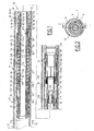
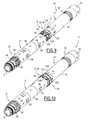
- the mandrel 10 comprises, from top to bottom, an upper sleeve 16 of longitudinal axis X-X ', an annular sealing element 18 radially deployable to provide a sealing barrier around the mandrel 10 on the inner wall 14, and an anchoring assembly 20 of the mandrel 10 radially deployable.
- the mandrel 10 is intended primarily for use in a well whose pressure under the mandrel 10 is greater than the pressure above the mandrel 10. It may be optionally used in a well whose pressure under the mandrel 10 is slightly less than the pressure above the mandrel 10.
- the mandrel 10 further comprises an operating tube 22 of the annular element 18 and the anchor assembly 20, means 24 for sequencing the radial expansion of the element 18 and the assembly 20, and means 26 for locking the operating tube 22 relative to the upper mandrel 16.
- the upper sleeve 16 and the tube 22 form a substantially tubular body of axis X-X '.
- the tubular sleeve 16 comprises, from top to bottom on the Figure 1 , a connection cap 28 to a cable working line via a laying tool and to a removal tool (not shown), a hollow intermediate tubular portion 30 and a convergent radial expansion portion 32 towards the bottom of the well, for supporting the annular sealing element 18.
- the cap 28 is adapted to receive a hollow tube deployment line ("coiled tubing") or a string of descent rods.
- the cap forms an interface with a liner or "straddle packer” or with another mandrel 10 placed in the same direction or in the opposite direction.
- the sleeve 16 defines, over its entire length, an internal passage 34 of axis X-X 'opening at the upper and lower ends of the sleeve 16.
- the connecting cap 28 includes a receiving groove of a connecting head to a cable working line (not shown), for deployment of the mandrel 10 into the well and its withdrawal from the well.
- the cable work line is for example described in the French application FR-A-2,848,363 of the Applicant.
- the intermediate tubular portion 30 is screwed under the cap 28. It defines in the vicinity of the cap 28, an annular groove 33 for receiving the releasable locking means 26. This annular groove 33 opens into the internal passage 34.
- the tubular portion 30 defines in the passage 34, in the vicinity of the radial expansion portion 32, a stop 36 of the lower actuating tube 22 as will be described in detail below.
- the radial expansion portion 32 externally has an upper conical surface 38 for supporting the annular sealing element 18 and centering steps 40 located under this conical surface 38.
- the conical surface 38 converges towards the bottom of the well. It extends on a periphery around the axis X-X '.
- Each centering step 40 has a peripheral surface of constant diameter about the axis XX 'extending downwardly in line with the conical surface 38.
- the step 40 has substantially the same thickness as the conical surface 38 at its end. lower.
- the steps 40 are spaced apart around the axis X-X '. They define between them notches delimited internally by the tube 22.
- the radial expansion portion 32 thus defines a first axial cam path extending from bottom to top along each step 40 and following the conical surface 38.
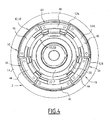
- the annular sealing element 18 comprises, moving along an outer peripheral surface 42 and an inner peripheral surface 43 around the longitudinal axis X-X ', an alternation of upper sealing blocks 44, forming a sealing assembly of the mandrel 10, and a plurality of lower centering blocks 46, forming a centering assembly of the mandrel 10.
- the centering assembly and the sealing assembly each comprise means 47A, 47B of radial return of each block 44, 46 against the operating tube 22, towards the axis X-X '.
- the upper blocks 44 and the lower blocks 46 are arranged head to tail along the longitudinal axis XX 'as described in the French application no. 05 12435 of the Applicant.
- the annular element 18 comprises three upper blocks 44 and three lower blocks 46.
- Each block 44, 46 delimits an outer face 48 of support on the conduit 12, an inner face 50 bearing on the sleeve 16 and two lateral surfaces 52A, 52B of expansion connecting the faces 48 and 50.
- Each block 44, 46 further has a lower surface 54A and an upper surface 54B substantially perpendicular to the axis XX 'on the Figure 10 .
- Each outer face 48 is of substantially cylindrical shape about the axis XX 'and forms a portion of the outer peripheral surface 42.
- Each inner face 50 has a conical shape converging upwardly along the axis XX' and forms a part of the inner peripheral surface 43.
- the inner faces 50 are shaped substantially conjugate to the conical surface 38 of the sleeve.
- the lateral surfaces 52A, 52B are of substantially helical shapes of axis X-X '.
- the lower blocks 46 and upper 44 have a generally trapezoidal shape in side view, with the height of each trapezium parallel to the longitudinal axis X-X '.
- the lateral surfaces 52A, 52B of each upper block 44 move away from each other by moving along the axis XX 'upwards while the lateral surfaces 52A, 52B of each lower block 46 converge. to one another following the same movement.
- Each block 44, 46 comprises a metal central armature 56, an outer seal 58 sealing on the conduit 12, and an inner seal 60 on the sleeve 16, mounted on either side of the armature 56.
- the armature 56 has a substantially I-shaped cross section. It thus has an upper edge and a lower edge interconnected by a central core of lower thickness than those of the upper edge and the lower edge.
- the upper and lower edges delimit with the central core an outer annular housing and an inner annular housing which respectively receive the liners 58 and 60.
- These housings open laterally into the lateral surfaces 52A, 52B of the block 44, 46 and are closed longitudinally by the lower edges and the upper edges.
- the creep of the linings 58, 60 is contained longitudinally in the inner and outer housings.
- the upper edge comprises, on either side of the central core, deformable lips axially and / or radially upwards when in contact with the inner wall of the duct 12 and with the conical surface 38 of the sleeve 16 under the effect of the deformation of the linings 54, 56.
- the armature 56 is for example made of metal.
- the fittings 58, 60 are for example made of elastomer or plastic.
- the inner liner 58 is placed in abutment on the conical surface 38, while the outer liner 60 is intended to be applied to the inner wall 14 of the duct 12.
- the lining 58, 60 are for example made by overmoulding on the frame 56 .
- the frame 56 may be made of plastic.
- the fittings 58 may be made of a softer metal than that of the frame 56, for example lead.
- the lower centering blocks 46 are displaceable longitudinally and radially with respect to the body on the first cam path, between a configuration contracted against the tube 22, a partially expanded centering configuration, and a totally expanded configuration resting on the conical surface 38.
- the upper sealing blocks 44 are movable radially and longitudinally in a coordinated manner with the lower blocks 46 relative to the body on the second cam path, between a radially contracted configuration offset longitudinally over the lower blocks 46 and a fully expanded configuration. nested in the lower blocks 46, as will be detailed below.
- the lower blocks 46 are arranged in abutment on the operating tube 22, under the step 40.
- the lower blocks 46 and have a minimum radial size.
- the upper blocks 44 also occupy their contracted position in partial support on the conical surface 38 and on the tube 22.
- the upper blocks 44 are offset longitudinally upwards relative to the lower blocks 46. Thus, the distance between the upper surface of an upper block 44, the upper surface of an adjacent lower block 46 is maximum, the blocks 44 , 46 then occupying a distant position.
- the annular element 18 is thus partially dislocated and has a minimal radial size.
- the mandrel 10 can be conveyed safely and easily in the conduit 12, limiting its risk of blockage in the conduit 12 and facilitating its counterflow of the flow of fluid passing through the conduit 12, while protecting the annular assembly 18.
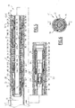
- the lower blocks 46 In their partially expanded configuration shown on the Figure 2 , the lower blocks 46 have been displaced longitudinally upwards relative to the upper blocks 44 to bear on a centering step 40 between two upper blocks 44. The lower blocks 46 then have a partially expanded configuration radially in which they form skates resting on the inner wall 14 of the duct 12. The upper blocks 44 are maintained in their substantially contracted configuration, in the space released by the radial expansion of the lower blocks 46.
- the lower blocks 46 and the upper blocks 44 delimit between them, through the annular element 18, axial passages 64 for the circulation of a fluid in the form of axial notches.
- the passages 64 are partially cleared for the passage of a fluid.
- Each axial passage 64 extends laterally between the lateral edges 52A, 52B of two adjacent lower blocks 46. It is delimited towards the X-X 'axis by the outer face 48 of an upper block 46, located radially close to the X-X' axis relative to the outer faces 48 of the adjacent lower blocks 44.
- passages 64 thus extend through the annular assembly 18 and open upwards and downwards through the annular assembly 18, between two lower blocks 44.
- the passages 64 extend radially inside the volume cylindrical defined by the outer faces 48 of the lower blocks 44.
- the interlocking of the lower blocks 46 between the upper blocks 44 by sliding the lateral surfaces 52A, 52B of the blocks 44, 46 on the lateral surfaces 52B, 52A of the adjacent blocks 46, 44 causes the expansion radial of the annular element 18 by both radial and circumferential wedge effect.
- the axial passages 64 delimited between the lower blocks 46 are then closed completely by the upper blocks 44 to seal through the annular element 18, around the upper sleeve 16.
- the annular element 18 thus has a maximum radial space with an outer peripheral surface 42 substantially cylindrical continuous over at least one periphery about the axis X-X ', and an inner peripheral surface 43 continues on at least one periphery around the 'X-X axis'.
- each block 44, 46 respectively open into the outer and inner housings of adjacent blocks 44, 46, so that the inner and outer liners 58, 60 extend continuously over at least a periphery around the X-X 'axis.
- the outer fittings 56 thus define the peripheral surface 42 external bearing support on the wall 14 of the conduit 12.
- the inner liners 60 define the inner peripheral surface 43 bearing on the surface 38 of the sleeve 16, continuous over at least one periphery about the axis X-X '.
- each lateral end of an upper edge of a block 44, 46 is applied at least partially to the lateral end of an upper edge of an adjacent block 44, 46.
- the lateral end of each lower edge of a block 44, 46 is applied to the lateral end of a lower edge of each adjacent block 44, 46.
- the ratio of the radial size of the annular element 18 in the expanded configuration to the radial size of the annular element 18 in the contracted configuration is thus between 1.05 and 1.50 and is preferably greater than 1 15.
- the annular element 18 in the contracted configuration is thus contained in the radial space of this element in the expanded configuration, and advantageously in the radial space of the sleeve 16.
- the radial return means 47A of the upper blocks 44 comprise, for each block 44, an upper longitudinal leg 70 of return, and a lower annular base 72 connecting the branches 70.
- Each branch 70 extends between an upper end 74 fixed on an upper block 44 and a lower end 76 integral with the annular ring 72.
- Each upper branch 70 is configured to press the upper blocks 44 radially towards the axis XX 'against the conical surface 38 and the operating tube 22.
- the ring 72 and the lower ends 76 are mounted to slide longitudinally on the operating tube 22. below the centering steps 40 without possibility of rotation about the axis X-X '.
- the annular base 72 is slidably mounted longitudinally with respect to the tube 22. It delimits longitudinal passages 86 for sliding the return means 47B of the lower blocks 46. No frangible connection member is interposed between the tube 22 and the base 72.
- the return means 47B of the lower blocks 46 comprise, for each block 46, a longitudinal return branch 78, and a peripheral sleeve 80, in which the longitudinal branches 78 are mounted.
- the return legs 78 extend between an upper end 82 fixed to the lower blocks 46, and a lower end 84 connected by a slide connection of axis X-X 'to the sleeve 80, through a passage 86.
- the jacket 80 is mounted longitudinally movable around the operating tube 22. It extends between the anchoring element 20 and the sealing element 18 to substantially completely cover the tube 22. No frangible connecting member is interposed between the tube 22 and the jacket 80.
- the jacket 80 extends opposite the return branches 78 and delimits longitudinal passages 86 of length slightly greater than the lower end 84 of the lower branches 78. A slight sliding axial axis XX 'of each end 84 in a passage 86 is possible, to allow a slight upward movement of the lower blocks 46 under the effect of the pressure after sealing around the mandrel 10.
- each lower block 46 is placed in abutment on the upper edge of the sleeve 80, during laying.
- the anchoring element 20 is offset longitudinally with respect to the annular sealing element 18.
- the element 18 is situated in the vicinity of the upper end of the mandrel 10
- the element anchoring 20 is located in the vicinity of the lower end of the mandrel 10 in a lower part of the operating tube 22.
- the distance between the anchor member 20 and the sealing member 18 is greater than at least twice the outer diameter of the sealing member in the expanded configuration of the blocks 44, 46.
- the anchoring element 20 comprises a plurality of anchoring dogs 90 angularly distributed around the axis X-X ', and for each dog 90, a branch 92 for radially biasing the dog 90 towards the axis X-X .
- the anchor dogs 90 have a toothed outer peripheral surface for indentation hooking on the inner wall 14 of the duct 12.
- the dogs 90 are deployable radially along a conical surface 94 of the tube 22, between a state retracted against the tube of maneuver 22 and a radially expanded state obtained before closing the axial passages 64 delimited between the lower blocks 46 and the upper blocks 44.
- the lower conical surface 94 converges upwardly and toward the upper conical surface 38.
- the dogs 90 delimit between them longitudinal ducts 96 allowing the passage of fluid.
- the return legs 92 extend longitudinally upwards between a lower end 98 fixed to a dog 90 and an upper end 100 connected by a slide connection of axis X-X 'to the return sleeve 80 above its lower edge.
- the branches 92 radially bias towards the X-X 'axis the dogs 90 against the lower conical surface 94 and against the tube 22.
- the operating tube 22 is slidably mounted in the tubular sleeve 16. It comprises an upper portion 110 disposed in the passage 34, a lower portion 112 which protrudes longitudinally downwardly outwardly of the sleeve 16. The lower assembly 11 is screwed to a lower end of the lower portion 112.
- the tube 22 defines a hollow central lumen 115 of axis X-X 'which opens at its upper end.
- the upper portion 110 externally has a smooth upper region and a lower region provided with a notch P-notching toothing 116 intended to cooperate with the locking means 26, as will be seen below.
- the upper portion 110 is delimited below by an annular rib 118 adapted to cooperate with the lower stop 36 to prevent the downward movement of the tube 22 beyond a lower position.
- the rib 118 forms a bearing piston for reducing the force exerted by the differential pressure applied to the mandrel 10 on the locking means 26.
- the tube 22 further comprises a traction support 120 disposed in the slot 115 for fastening the laying tool.
- the traction support 120 is placed in the vicinity of the rib 118. It is connected to the wall of the operating tube 22 by a calibrated shattered washer 121.
- the wall of the tube 22 defines an outer annular housing 122A.
- the housing 122A receives a shear matrix 122B and an outer portion 122C of the frangible washer 121 placed under the die 122B.
- the wall of the support 120 defines an inner annular housing 123A, placed opposite the outer housing 122A.
- the housing 122B receives an annular clamping punch 123B and an inner portion 123C of the washer 121.
- the punch 123B and the die 122B are advantageously made of ceramic.
- the washer 121 is cut between its outer portion 122C and its inner portion 123C, by punching along the periphery of the support 120, to release the tube 22 relative to the support 120.
- Punching cutting makes it possible to easily adjust the breaking force necessary to cut the washer 121 by choosing the thickness and the material constituting the washer 121. This cut is clean and avoids the presence of debris in the tube 22 after cutting and allows to maintain the inner surface of the smooth tube 22 avoiding singularities in the flow, sources of erosion.
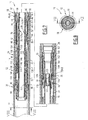
- the operating tube 22 is movable longitudinally with respect to the sleeve 16 between a lower rest position ( Figure 1 ) in which the upper blocks 44 and the lower blocks 46 occupy their contracted configuration, a first intermediate centering position ( Figure 3 ) in which the lower blocks 46 occupy their partially expanded configuration in abutment on the centering steps 40, a second intermediate anchoring position ( Figure 5 ) in which the anchor dogs 90 occupy their expanded state, and the axial passages 64 remain unobstructed, and a top sealing position ( Figure 7 ), in which the upper blocks 44 and the lower blocks 46 are nested within each other and form a sealed annular assembly around the sleeve 16 to close the axial passages 64.
- the sequencing means 24 further comprise a lower spring 136 for biasing the anchor dogs 90 towards their retracted state and an upper spring 138 for biasing the lower blocks 46 and the upper blocks 44 towards their configuration. contracted.
- the lower stop 130 extends around the operating tube 22, above the lower assembly 11.
- the lower stop 130 has an upper radial surface 140 for supporting the lower spring 136.
- the intermediate stop 132 is integral with the sleeve 80. It projects radially towards the tube 22 from the sleeve 80. It has an inner peripheral surface 142 which bears on the tube 22, and on both sides of the tube. the surface 142, a lower radial surface 144 for supporting the lower spring 136 and an upper radial surface 146 for supporting the upper spring 138.
- the upper abutment 134 secured to the sleeve 16 extends under the conical surface 38 and under the step 40 around the operating tube 22.
- the abutment 134 internally delimits passages 148 for sliding the lower ends 76 of the longitudinal legs 70 for returning the blocks. 44, in which the lower ends 76 are slidably received longitudinally.
- the upper stop 134 has a bottom surface 150 for supporting the upper spring 138.
- the springs 136, 138 are connected in series. They are maintained prestressed initially, respectively between the stops 130 and 132 and between the stops 132 and 134, in the lower rest position of the tube 22.
- the lower spring 136 is a helical spring or corrugated coil. It is located radially between the operating tube 22 and the outer sleeve 80. It is supported longitudinally on the one hand, on the upper surface 140 of the lower stop 130, and on the other hand, on the lower bearing surface. 144 of the movable intermediate stop 132.
- the upper spring 138 is also a helical spring or corrugated coil. It is housed radially between the operating tube 22 and the jacket 80. It is supported longitudinally on the one hand, on the upper surface 146 of the intermediate stop 132 and on the other hand, on the lower surface 150 of the upper stop 134.
- the respective stiffnesses of the springs 136, 138 and / or the respective initial prestressing applied on the springs 136, 138 are chosen significantly different, in order to obtain a sequential and smooth deployment of the lower blocks 46, anchoring dogs 90 and upper blocks 44.
- the stiffness of the lower spring 136 is chosen to be greater than 1.3 times the stiffness of the upper spring 138, and the prestressing of the lower spring 136 of the upper spring 138 are substantially equal.
- the sequencing means 24 are devoid of any frangible link member.
- the lower blocks 46, the upper blocks 44 and the anchoring element 20 are slidably mounted around the tube 22 and the sleeve 16, without the interposition of a frangible connecting member, the sequencing of the deployment being obtained solely by the choice of the stiffness ratio of the springs 136, 138 and / or the ratio of their initial prestressing.
- the locking means 26 comprise, from top to bottom on the Figures 1 , 3 , 5 , 7 and 11 , a ring 162 for releasing the tube 22 and a clamp 164 for locking the tube 22.
- the release ring 162 is formed by a substantially cylindrical sleeve.
- the ring 162 is movable between an upper holding position of the clamp 164, and a lower position of release of the clamp 164 by elastic return. It delimits externally an annular housing 167.
- the clamp 164 is also tubular. It comprises an upper bead 168 locking in longitudinal position, and an inner toothed surface 170 for snapping the tube 22 slotted axially.
- An axially slotted upper ring 172A and an axially slotted lower ring 172B are externally engaged in the internal toothed surface 170, between this surface 170 and the tube 22.
- Each intermediate ring 172A, 172B has an inner ratcheting surface of the tube 22 and a outer toothed surface 174A, 174B.
- the toothed surfaces 174A, 174B are likewise not “P" equal to the pitch of the toothing 116. However, the surfaces 174A, 174B are screwed into the toothed surface 170 with their teeth having a longitudinal offset of half a step "P". / 2 "to allow successive and cyclic engagement of the toothing 116 with each of the toothed surfaces 174A, 174B.
- a peg 176A, 176B introduced into each slot on either side of the toothed surface 170 maintains the angular position of each ring 172A, 172B with respect to the toothed surface 170.
- the locking clip 164 is axially movable between an upper locking position of the tube 22, in which the bead 168 is received in the annular groove 33 of the sleeve 16, and a lower position in which the bead 168 is received in the housing 167 of the release ring.
- the mandrel 10 is placed in a descent configuration in the duct 12.
- the tube 22 is placed in its lower rest position in which the distance between the upper conical surface 38 on the sleeve 16 and the lower conical surface 94 on the tube 22 is maximum.
- the lower blocks 46 and the upper blocks 44 occupy their contracted configuration against the tube 22.
- the lower blocks 46 are held in abutment on the tube 22 under the step 40 by the lower branches 78.
- the upper blocks 44 are offset longitudinally to the top compared to the lower blocks 46.
- the upper blocks 44 also rest on the tube 22 under the effect of the radial return generated by the upper branches 70.
- the annular assembly 18 then occupies a minimum radial size, less than or equal to the maximum radial size of the body 16 , 22 and shirt 80.
- the return legs 92 hold the anchoring dogs 90 against the tube 22 above the conical surface 94.
- the dogs 90 then occupy their retracted state, which allows easy descent into the duct 12, without risk of damage to the annular element 18 and dogs 90.
- the minimum gap between the mandrel 10 and the inner wall 14 of the duct 12 is maximized and wide enough to limit the problems due to the displacement of the countercurrent mandrel 10 of the fluid flow present in the duct 12, or to prevent the mandrel 10 be driven by a current.
- the release ring 162 is arranged so that the annular housing 167 extends above the upper bead 168 of the locking clip 164, which is locked in position in the annular groove 33.
- a laying tool is also inserted in the central lumen 115 before the descent into the well to cooperate with the traction support 120 and the connecting cap 28.
- This tool then has a fixed part (not shown) supported and / or hooked on the cap 28 and a movable part (not shown) embedded in the traction support 120.
- the mandrel 10 is then lowered into the duct 12 by hooking the laying tool to a working line.
- the setting tool moves the traction support 120 upwardly by holding the sleeve 16 longitudinally fixed with respect to the conduit 12.
- the tube 22 then passes from its rest position to its first intermediate centering position, represented on the Figure 3 .
- the upper blocks 44 fit into the space created by the radial expansion of the lower blocks 46.
- the lower spring 136 When moving the operating tube 22 upwards, the lower spring 136 is preferably compressed between the stops 130, 132 relative to the upper spring 138 given their stiffness and / or initial prestressing. Thus, the approaching stroke of the lower stop 130 towards the intermediate stop 132 is greater than the approaching stroke of the intermediate stop 132 towards the upper stop 134.
- the lower blocks 46 and the dogs 90 being deployed radially, they constitute radial centering pads of the mandrel 10. This makes it possible to center the axis XX 'of the mandrel with respect to the axis of the conduit 12. However, this centering is carried out leaving partially clear the axial passages 64 defined between the lower blocks 46 partially expanded and the upper blocks 44 contracted, and the passageways 96 between the dogs 90 free. A flow of fluid around the mandrel 10 is thus possible through the passages 64 and the ducts 96. This fluid flow limits the piston effect that could be obtained if the duct 12 was completely closed by the mandrel 10, the latter 10 being not anchored yet.
- the upper part 110 of the tube rises in the locking clip 164.
- the external toothing 116 of the upper part 110 remains under the internal toothed surface 170A , which allows the return of the tube 22 to its rest position, if the position of the mandrel must be changed, or in case of failure of the laying tool.
- the tube 22 is again displaced upwards relative to the sleeve 16 to reach its second intermediate anchoring position represented on the Figure 5 .
- the anchor dogs 90 then penetrate into the wall 14 to ensure the efficient attachment of the mandrel 10 in position in the duct 12, by indentation and slight radial deformation of the tube 14.
- the relative displacement of the tube 22 relative to the sleeve 16 is continued by moving the sleeve 16 downwards, the tube 22 remaining fixed relative to the conduit 12, abutting the dogs.
- the upper return spring 138 is compressed between the upper stop 134 and the intermediate stop 132, which causes the longitudinal displacement of the upper blocks 44 towards the lower blocks 46 then the radial expansion of the upper blocks 44 along the conical surface 38 to reach their expanded configuration bearing on the inner wall 14 of the duct 12.
- the conical surface 38 reaches the lower blocks 46, which produces a relative longitudinal displacement of the blocks 46 relative to the upper blocks 44.
- the blocks 46 then enter between the upper blocks 44 to close the axial passages 64 and seal around the annular element 18.
- the outer peripheral surface 42 of the annular element 18, formed by the peripheral faces 50 of support on the conduit 14 is continuous over at least one periphery about the axis X-X '.
- This outer peripheral surface 42 is applied against the inner wall 14 to seal around the mandrel 10.
- the continuity of the outer peripheral surface 42 is provided by the triaxial compression of the outer liners 58 in the outer annular housings.
- the inner peripheral faces 50 of the blocks 44, 46 are applied by deformation against the conical surface 38.
- the inner peripheral surface 43 of the annular sealing element 18, formed by the inner peripheral faces 50, is continuous over at minus one periphery around the X-X 'axis. This inner peripheral surface 43 is applied against the bearing surface 38 of the sleeve 16 to seal between the annular element 18 and the sleeve 16.
- the tube 22 then occupies its upper sealing position represented on the Figure 7 . In this position, the distance between the upper conical surface 38 of the lower conical surface 94 is minimal.
- the tube 22 then occupies its upper sealing position represented on the Figure 7 . In this position, the distance between the upper conical surface 38 of the lower conical surface 94 is minimal.
- a tool (not shown) is inserted into the passageway 115 to cause the ring 162 to move downwardly relative to the cap 28.
- the beads 168 penetrate into the housings 167, and are extracted from the annular grooves 33.
- the assembly formed by the release ring 162, the locking clip 164, the split rings 172A, 172B and the tube 22, is then free to slide downwardly in the passage 34. Under the effect of the springs 136, 138 the tube 22 also moves downwards from its upper position to its second intermediate position and then to its initial position until the annular rib 118 abuts against the abutment 36.
- the release of the springs 136, 138 causes the downward movement of the tube 22, and the upward movement of the sleeve 16 relative to the sleeve 80.
- the upper spring 138 pushes the sleeve 16 upwards, then the annular base 72 to move longitudinally the lower blocks 46 relative to the upper blocks 44 and thereby cause the disengagement of the annular element 18 and the release of the axial passages 64.
- the lower blocks 46 and the upper blocks 44 then occupy their contracted configuration, and the anchor dogs 90 occupy their retracted state.
- the mandrel 10 is then raised easily and simply towards the surface in the duct 12.
- the mandrel 10 is also configurable for use mainly in a well for which the pressure above the mandrel is greater than that below the mandrel 10. It may optionally be used in a well whose pressure above the mandrel 10 is slightly less than the pressure under mandrel 10.
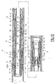
- the first radial expansion surface 32, the second radial expansion surface 94, the annular sealing assembly 18, the anchor assembly 20 and the sequencing means 24 are reversibly dismountable relative to the mandrel 16 and to the tube 22, between the upper functional configuration described on the Figures 1 to 10 , and the lower functional configuration described on the Figure 12 .
- the first radial expansion surface 32 and the annular sealing assembly 18 have been returned relative to a plane transverse to the axis XX 'and have been mounted at the lower end of the tube 22 .
- the first radial expansion surface 32 has a conical portion 38 converging upwardly.
- the centering blocks 46 are located above the sealing blocks 44.
- the anchor dogs 90 have been raised above the annular sealing assembly to be placed in abutment on the second radial expansion surface 94.
- the jacket 80 was turned over and the spring 136 of high stiffness was placed under the spring 138 of low stiffness.
- the second mandrel 210 comprises an annular sealing element 18 constituted by a radially expandable annular centering seal 212 and two radially deployable annular closure elements 214 placed longitudinally on either side of the annular centering seal 212.
- Each liner 212, 214 is deployable between a configuration contracted against the sleeve 16 and an expanded configuration in which they occupy a maximum diameter.
- the centering lining 212 delimits three axial passages 64 distributed around the axis X-X '.
- the axial passages 64 extend through the liner 212 between an upper surface and a lower surface of the centering liner 212 where they open. They form longitudinal notches opening radially outwards.
- the gaskets 214 are disposed on either side of the axial passages 64. In the contracted configuration of the gaskets 214, the axial passages 64 are disengaged, whereas in their expanded configuration, the gaskets 214 close the axial passages 64 to the gaskets 214. up and down.
- the second mandrel 210 has an operation similar to that of the first mandrel.
- the centering lining 212 and the anchoring dogs 90 are deployed radially at least partially to ensure a centering of the axis XX 'of the mandrel 10 with respect to the axis of the duct 12, by contact between the inner wall 14 and the lining 214 and the dogs 90.
- annular seal gaskets 214 are held in their substantially retracted configuration to maintain the axial passages 64 clear.
- the anchor dogs 90 are deployed substantially completely to ensure the attachment of the mandrel in the wall 14 of the conduit 12 leaving the axial passages 64 cleared. This avoids the piston effect during this fixation.
- the seals 214 located on either side of the centering lining 212 are deployed radially to bear against the wall 14 of the duct, and against the upper surface and the lower surface of the centering lining. 212. This causes, on the one hand, the seal between the sleeve 16 and the duct 12, and on the other hand the closure of the axial passages 64 of the centering lining 212.
- the centering assembly of the closure assembly of the annular sealing element is adjacent longitudinally, that is to say that the distance that separates longitudinally the centering assembly from the shutter assembly is zero or reduced, for example less than the maximum diameter of the annular sealing member deployed.
Landscapes
- Engineering & Computer Science (AREA)
- Mining & Mineral Resources (AREA)
- Geology (AREA)
- General Engineering & Computer Science (AREA)
- Life Sciences & Earth Sciences (AREA)
- Environmental & Geological Engineering (AREA)
- Fluid Mechanics (AREA)
- Mechanical Engineering (AREA)
- General Life Sciences & Earth Sciences (AREA)
- Geochemistry & Mineralogy (AREA)
- Physics & Mathematics (AREA)
- Piles And Underground Anchors (AREA)
- Quick-Acting Or Multi-Walled Pipe Joints (AREA)
- Pipe Accessories (AREA)
- Media Introduction/Drainage Providing Device (AREA)
- Prostheses (AREA)
Claims (14)
- Dorn (10; 210), der vorgesehen ist, in eine Leitung (12) für die Zirkulation eines Fluids eingeführt zu werden, umfassend:- einen Körper (16, 22), der eine Längsachse (X-X') aufweist;- ein ringförmiges radial expansibles Dichtungselement (18), das eine Zentrieranordnung (46; 212) und eine Verschließanordnung (44; 214) der Zentrieranordnung (46; 212) umfasst, wobei jede Anordnung (46, 44; 214, 212) in Bezug auf den Körper (16, 22) radial von einer zusammengezogenen Konfiguration in eine ausgedehnten Konfiguration ausfahrbar ist, wobei das ringförmige Dichtungselement (18) eine durchgehende Umfangsfläche (42) zum Anlegen an die Leitung (12) und eine durchgehende Umfangsfläche (43) zum Anlegen an den Körper (16, 22) definiert, wenn die Zentrieranordnung (46; 212) und die Verschließanordnung (44; 214) ihre ausgedehnten Konfigurationen einnehmen;- ein radial expansibles Ankerelement (20), das in Längsrichtung zu der ringförmigen Dichtungsanordnung (18) beabstandet ist, wobei das Ankerelement (20) zwischen einem zurückgezogenen Zustand und einem ausgefahrenen Zustand, in dem es mindestens einen axialen Kanal (96) begrenzt, bewegbar ist;- Abfolgemittel (24), die geeignet sind, radial die Zentrieranordnung (46; 212) und das Ankerelement (20) vor der Verschließanordnung (44; 214) auszufahren;dadurch gekennzeichnet, dass die Zentrieranordnung (46; 212) eine mindestens teilweise ausgedehnte Konfiguration aufweist,
in der sie mindestens einen axialen Durchgang (64) definiert, der sich durch das ringförmige Dichtungselement (18) erstreckt, wobei die Verschließanordnung (44; 214) radial den oder jeden axialen Durchgang (64) bei ihrem Ausfahren von ihrer zusammengezogenen Konfiguration in ihre ausgedehnte Konfiguration verschließt, wobei das Ankerelement (20) im Wesentlichen in seinem ausgefahrenen Zustand bei dem radialen Ausfahren der Verschließanordnung (44; 214) verbleibt. - Dorn (10; 210) nach Anspruch 1, dadurch gekennzeichnet, dass der Körper (16; 22) eine erste Fläche (32) zur radialen Expansion der Zentrieranordnung (46; 212) und der Verschließanordnung (44; 214) und eine zweite Fläche (94) zur radialen Expansion der Ankeranordnung (20) begrenzt, die in Längsrichtung in Bezug auf die erste Fläche (32) zur radialen Expansion beweglich ist, zwischen:- einer entfernten Position, in der die Zentrieranordnung (46; 212) und die Verschließanordnung (44; 214) ihre zusammengezogene Position einnehmen, wobei das Ankerelement (20) seinen zurückgezogenen Zustand einnimmt;- einer Zwischenposition der Zentrierung, in der die Zentrieranordnung (46; 212) ihren zumindest teilweise ausgedehnten Zustand einnimmt, wobei der oder jeder axiale Durchgang (64) und der oder jeder axiale Kanal (96) zumindest teilweise freigesetzt ist, und- einer herangerückten Verschließposition, bei der die Verschließanordnung (46; 214) ihre ausgedehnte Konfiguration einnimmt, um den oder jeden axialen Durchgang (64), der von der Zentrieranordnung (46; 212) definiert wird, zu verschließen.
- Dorn (10; 210) nach Anspruch 2, dadurch gekennzeichnet, dass der Körper (16; 22) umfasst:- eine Hülse (16), die eine von der ersten Fläche (32) der radialen Expansion und der zweiten Fläche (94) der radialen Expansion trägt;- ein Rohr (22), das gleitend in der Hülse (16) angeordnet ist und die andere von der ersten Fläche (32) der radialen Expansion und der zweiten Fläche (94) der radialen Expansion trägt;wobei die Zentrieranordnung (46), die Dichtungsanordnung (44) und das Ankerelement (20) gleitend um den Körper (16; 22) ohne die Zwischenanordnung eines brechbaren Verbindungsorgans zwischen jedem dieser Teile angeordnet sind.
- Dorn (10; 210) nach einem beliebigen der Ansprüche 2 bis 3, dadurch gekennzeichnet, dass die erste radiale Fläche (32) einen ersten Nockenpfad (38, 40) für die radiale Expansion der Zentrieranordnung (46; 212) und einem zweiten Nockenpfad (38) für die radiale Expansion der Verschließanordnung (44; 214) mit einem zu dem ersten Nockenpfad (38; 40) unterschiedlichen Profil definiert, wobei der erste Nockenpfad (38, 40) eine Stufe (40) der radialen Expansion, um die Zentrieranordnung (46; 212) von ihrer zusammengezogenen Konfiguration in die zumindest teilweise ausgedehnte Konfiguration zu bringen, und eine konische Fläche (38) umfasst, um die radiale Expansion der Zentrieranordnung (42; 212) in ihre ausgedehnte Konfiguration hervorzurufen.
- Dorn (10; 210) nach einem beliebigen der Ansprüche 2 bis 4, dadurch gekennzeichnet, dass die erste Fläche der radialen Expansion (32), die zweite Fläche der radialen Expansion (94), die ringförmige Dichtungsanordnung (18), die Ankeranordnung (20) und die Abfolgemittel (24) in reversibler Weise in Bezug auf den Körper (16; 22) demontierbar sind, zwischen:- einer oben liegenden Funktionskonfiguration, in der die erste Fläche (32) der radialen Expansion und die ringförmige Dichtungsanordnung (18) in Längsrichtung über der zweiten Fläche (94) der radialen Expansion und der Ankeranordnung (20) angeordnet sind; und- einer unten liegenden Funktionskonfiguration, in der die erste Fläche (32) der radialen Expansion und die ringförmige Dichtungsanordnung (18) in Längsrichtung unter der zweiten Fläche (94) der radialen Expansion und der Ankeranordnung (20) liegen.
- Dorn (10; 210) nach einem beliebigen der Ansprüche 2 bis 5, dadurch gekennzeichnet, dass die Abfolgemittel ein erstes Organ (136) der elastischen Belastung des Ankerelements (20) in seinen zurückgezogenen Zustand und ein zweites Organ (138) der elastischen Belastung der Zentrieranordnung (46; 212) und der Verschließanordnung (44; 214) in ihre zusammengezogene Konfiguration umfassen,
und dass das erste Organ (136) der Belastung und das zweite Organ (138) der Belastung anfänglich vorgespannt sind und in Reihe zwischen der ersten Fläche (32) der radialen Expansion und der zweiten Fläche (94) der radialen Expansion angeordnet sind, wobei das erste Organ (136) der Belastung eine Steifigkeit und/oder eine anfängliche Vorspannung unterschiedlich zu der des ersten Organs (138) der Belastung aufweist, um ein aufeinanderfolgendes kontinuierliches Ausfahren der Zentrieranordnung (46; 212), des Ankerelements (20), dann der Verschließanordnung (44; 214) zu erhalten. - Dorn (10; 210) nach einem beliebigen der Ansprüche 2 bis 6, dadurch gekennzeichnet, dass er Mittel (26) zum Blockieren der Verschiebung der ersten Fläche (32) der radialen Expansion fern von der zweiten Fläche (94) der radialen Expansion umfasst, wobei diese Mittel zum Blockieren (26) nur jenseits der Zwischenposition der Zentrierung aktivierbar sind.
- Dorn (10; 210) nach Anspruch 7, dadurch gekennzeichnet, dass die Mittel zum Blockieren (26) umfassen:- eine erste gezahnte Fläche (170), die mit einem ersten, die erste Fläche (32) der radialen Expansion tragenden Organ (16), verbunden ist;- eine zweite gezahnte Fläche (116) mit Teilung P, die mit einem die zweite Fläche (94) der radialen Expansion tragenden Organ (22) verbunden ist;- mindestens N gezahnte Ringe (172A, 172B), N größer als 1, die zwischen der ersten gezahnten Fläche (170) und der zweiten gezahnten Fläche (116) angeordnet sind, wobei die Ringe (172A, 172B) Verzahnungen mit in Längsrichtung um P/N versetzter Teilung aufweisen, um die erste gezahnte Fläche (170) mit der zweiten gezahnten Fläche (160) in aufeinanderfolgender Weise und zyklisch mittels jedem der N Ringe (172A, 172B) bei der Verschiebung der ersten Fläche (32) der radialen Expansion zu der zweiten Fläche (94) der radialen Expansion in Eingriff zu bringen.
- Dorn (10; 210) nach einem beliebigen der Ansprüche 2 bis 8, dadurch gekennzeichnet, dass er einen Zugträger (120) umfasst, der an dem Handhabungsrohr (22) mittels eines brechbaren Umfangsorgans (121) befestigt ist, wobei der Zugträger (120) von dem Handhabungsrohr (22) durch Lochungen des brechbaren Umfangsorgans (121) längs eines Umfangs des Zugträgers (120) trennbar ist, und dass das brechbare Umfangsorgan (121) eine austarierte Scheibe mit konstanter Dicke ist, um unter der Wirkung einer vorbestimmten Längstrennkraft zwischen dem Zugträger (120) und dem Handhabungsrohr (22) zerbrochen zu werden.
- Dorn (10; 210) nach einem beliebigen der vorhergehenden Ansprüche, dadurch gekennzeichnet, dass die Zentrieranordnung (46) eine Vielzahl von Zentrierblöcken umfasst, die lateral zueinander um die Längsachse (X-X') in der ausgedehnten Konfiguration der Zentrieranordnung (46) beabstandet sind, wobei die Verschließanordnung (44) eine Vielzahl von Verschließblöcken umfasst, die in dichter Weise zwischen die Zentrierblöcke (46) in ihrer ausgedehnten Konfiguration geschachtelt sind, und dass das Ankerelement (20) eine Vielzahl von Ankerspannelementen (90) umfasst, die winkelmäßig um die Längsachse (X-X') verteilt sind.
- Dorn (10; 210) nach Anspruch 10, dadurch gekennzeichnet, dass die Zentrieranordnung (46) und die Verschließanordnung (44) jeweils Arme (70, 78) zur radialen Belastung jedes Zentrierblocks (46) und jedes Verschließblocks (44) in Richtung der Längsachse (X-X') umfassen, wobei das Ankerelement (20) Arme (92) zum Rückführen der Spannelemente (90) in Richtung der Längsachse (X-X') umfasst.
- Dorn (10; 210) nach Anspruch 11, dadurch gekennzeichnet, dass die Arme (78) zur radialen Belastung der Zentrierblöcke (46) und/oder die Arme (92) zum Rückführen mit einem Längsspiel in einem Käfig (80) verbunden sind, der in Längsrichtung gleitend um den Körper (16; 22) herum angeordnet ist.
- Dorn (10; 210) nach einem beliebigen der vorhergehenden Ansprüche, dadurch gekennzeichnet, dass in der zusammengezogenen Konfiguration die ringförmige Anordnung (18) einen radialen Platzbedarf kleiner oder gleich dem maximalen radialen Platzbedarf des Körpers (16, 22) einnimmt.
- Verfahren zur Instellungbringung eines Dorns (10; 210) nach einem beliebigen der vorhergehenden Ansprüche in eine Leitung (12) zur Zirkulation eines Fluids, dadurch gekennzeichnet, dass es die folgenden Schritte umfasst:- Einführen und Weiterbewegen des Dorns (10; 210) in die bzw. der Leitung (12), wobei die Zentrieranordnung (46; 212) und die Verschließanordnung (44; 214) ihre zusammengezogenen Konfigurationen einnehmen, wobei das Ankerelement (20) seinen zurückgezogenen Zustand einnimmt; dann, wenn der Dorn eine gewünschte Position in der Leitung erreicht:- radiales Ausfahren der Zentrieranordnung (46; 212) in ihre zumindest teilweise ausgedehnte Konfiguration und der Ankeranordnung (20) in ihren ausgefahrenen Zustand, um das Ankerelement (20) und die Zentrieranordnung (46; 212) zumindest teilweise gegen die Innenwand (14) der Leitung (12) zu drücken und den Körper (16; 22) fern von der Innenwand (14) zu halten, wobei der oder jeder axiale Durchgang (64) und der oder jeder axiale Kanal (96) zumindest teilweise freigelassen wird, um den Durchgang eines Fluids durch den oder jeden axialen Durchgang (64) und durch den oder jeden axialen Kanal (96) zu ermöglichen; dann- Bewegen der Verschließanordnung (44; 214) in ihre ausgedehnte Konfiguration, um den oder jeden axialen Durchgang (64) zu verschließen und eine Umfangsfläche (42) des Andrückens der ringförmigen Dichtungsanordnung (18) an die Leitung (12) und eine Umfangsfläche (43) des Andrückens der ringförmigen Dichtungsanordnung (18) an den Körper (16; 22) zu definieren, die über mindestens einen Umfang um die Längsachse (X-X') durchgehend sind, wobei das Ankerelement (20) im Wesentlichen in seinem ausgefahrenen Zustand bei dem radialen Ausfahren der Verschließanordnung (44; 214) verbleibt.
Applications Claiming Priority (2)
| Application Number | Priority Date | Filing Date | Title |
|---|---|---|---|
| FR0753057A FR2912202B1 (fr) | 2007-02-05 | 2007-02-05 | Mandrin destine a etre introduit dans un conduit de circulation d'un fluide, et procede de mise en place associe |
| PCT/FR2008/050175 WO2008104675A1 (fr) | 2007-02-05 | 2008-02-04 | Mandrin et procede de mise en place associe |
Publications (2)
| Publication Number | Publication Date |
|---|---|
| EP2118552A1 EP2118552A1 (de) | 2009-11-18 |
| EP2118552B1 true EP2118552B1 (de) | 2013-04-24 |
Family
ID=38514170
Family Applications (1)
| Application Number | Title | Priority Date | Filing Date |
|---|---|---|---|
| EP08762034.0A Not-in-force EP2118552B1 (de) | 2007-02-05 | 2008-02-04 | Rohrleitungsverschluss und verfahren zum einbringen desselben |
Country Status (8)
| Country | Link |
|---|---|
| US (1) | US8418772B2 (de) |
| EP (1) | EP2118552B1 (de) |
| JP (1) | JP5356254B2 (de) |
| AU (1) | AU2008220699B2 (de) |
| BR (1) | BRPI0806383A2 (de) |
| CA (1) | CA2677252C (de) |
| FR (1) | FR2912202B1 (de) |
| WO (1) | WO2008104675A1 (de) |
Cited By (1)
| Publication number | Priority date | Publication date | Assignee | Title |
|---|---|---|---|---|
| US10760372B2 (en) | 2018-12-19 | 2020-09-01 | Weatherford Technology Holdings, Llc | High expansion well tool and associated methods |
Families Citing this family (11)
| Publication number | Priority date | Publication date | Assignee | Title |
|---|---|---|---|---|
| US10364629B2 (en) | 2011-09-13 | 2019-07-30 | Schlumberger Technology Corporation | Downhole component having dissolvable components |
| US9752407B2 (en) | 2011-09-13 | 2017-09-05 | Schlumberger Technology Corporation | Expandable downhole seat assembly |
| US9528336B2 (en) | 2013-02-01 | 2016-12-27 | Schlumberger Technology Corporation | Deploying an expandable downhole seat assembly |
| US10487625B2 (en) | 2013-09-18 | 2019-11-26 | Schlumberger Technology Corporation | Segmented ring assembly |
| US9644452B2 (en) | 2013-10-10 | 2017-05-09 | Schlumberger Technology Corporation | Segmented seat assembly |
| NO20150683A1 (en) * | 2015-05-28 | 2016-11-29 | Interwell Technology As | Casing plug assembly and anchor module for such an assembly |
| US10538988B2 (en) | 2016-05-31 | 2020-01-21 | Schlumberger Technology Corporation | Expandable downhole seat assembly |
| US10648263B2 (en) * | 2016-12-19 | 2020-05-12 | Schlumberger Technology Corporation | Downhole plug assembly |
| CN115405279B (zh) * | 2022-08-26 | 2023-09-15 | 武汉华工融军科技有限公司 | 一种液电脉冲激波石油增产装置 |
| US12305458B2 (en) * | 2022-12-02 | 2025-05-20 | Halliburton Energy Services, Inc. | Internal slip design with minimum backlash for packers seal enhancement |
| US12385339B2 (en) | 2022-12-02 | 2025-08-12 | Halliburton Energy Services, Inc. | Internal slip including one or more symmetrical teeth |
Family Cites Families (39)
| Publication number | Priority date | Publication date | Assignee | Title |
|---|---|---|---|---|
| US1536370A (en) * | 1923-03-07 | 1925-05-05 | Regan Forge & Eng Co | Oil-well packer |
| US1604771A (en) * | 1925-08-10 | 1926-10-26 | Harrison M Gill | Liner adapter for well casings |
| US2178161A (en) * | 1936-12-24 | 1939-10-31 | Grant John | Strainer cleaner |
| US2230721A (en) | 1937-02-09 | 1941-02-04 | Gen Electric | Electric switch |
| US2262117A (en) * | 1939-01-19 | 1941-11-11 | Roe Mfg Company | Well plugging device |
| US2230712A (en) * | 1940-04-11 | 1941-02-04 | Bendeler William | Well bridging plug |
| US2376605A (en) * | 1942-01-28 | 1945-05-22 | Richard R Lawrence | Wire line safety control packer |
| US2715441A (en) * | 1951-05-24 | 1955-08-16 | Dresser Ind | Bridging plug |
| US2845126A (en) * | 1952-10-03 | 1958-07-29 | Cicero C Brown | Well packers |
| US3000443A (en) * | 1957-08-19 | 1961-09-19 | Dresser Ind | Bridging plug |
| US3467186A (en) * | 1967-08-15 | 1969-09-16 | Schlumberger Technology Corp | Well tool with expansible anchor and friction drag |
| US3572433A (en) * | 1969-05-08 | 1971-03-23 | Baker Oil Tools Inc | Through tubing cementing plug apparatus |
| USRE31978E (en) * | 1980-02-19 | 1985-09-03 | Baker Oil Tools, Inc. | Well tool having knitted wire mesh seal means and method of use thereof |
| US4494793A (en) * | 1982-09-17 | 1985-01-22 | Parma Corporation | Trigger release mechanism for reclining chair |
| US4590995A (en) * | 1985-03-26 | 1986-05-27 | Halliburton Company | Retrievable straddle packer |
| US4765404A (en) * | 1987-04-13 | 1988-08-23 | Drilex Systems, Inc. | Whipstock packer assembly |
| US4862961A (en) * | 1988-06-09 | 1989-09-05 | N.A.R.K. Properties | Retrievable tension-set packer |
| US4949793A (en) * | 1989-04-28 | 1990-08-21 | Baker Hughes Incorporated | Method and apparatus for completion of a well |
| DE3935093A1 (de) * | 1989-10-21 | 1991-04-25 | Daimler Benz Ag | Abgasrueckfuehreinrichtung fuer einen verbrennungsmotor |
| GB2246585B (en) * | 1990-07-31 | 1995-03-22 | Masx Energy Services Group Inc | Hydraulically set anchor for well tools |
| US5564503A (en) * | 1994-08-26 | 1996-10-15 | Halliburton Company | Methods and systems for subterranean multilateral well drilling and completion |
| US6234249B1 (en) * | 1997-02-06 | 2001-05-22 | Bronnteknologiutvikling As | Device for use with a retrievable bridge plug |
| US5988276A (en) * | 1997-11-25 | 1999-11-23 | Halliburton Energy Services, Inc. | Compact retrievable well packer |
| US6167963B1 (en) * | 1998-05-08 | 2001-01-02 | Baker Hughes Incorporated | Removable non-metallic bridge plug or packer |
| US6131663A (en) * | 1998-06-10 | 2000-10-17 | Baker Hughes Incorporated | Method and apparatus for positioning and repositioning a plurality of service tools downhole without rotation |
| AU2003210914B2 (en) * | 2002-02-11 | 2007-08-23 | Baker Hughes Incorporated | Repair of collapsed or damaged tubulars downhole |
| US6769491B2 (en) * | 2002-06-07 | 2004-08-03 | Weatherford/Lamb, Inc. | Anchoring and sealing system for a downhole tool |
| US6695051B2 (en) * | 2002-06-10 | 2004-02-24 | Halliburton Energy Services, Inc. | Expandable retaining shoe |
| US6892820B2 (en) * | 2002-08-09 | 2005-05-17 | Schlumberger Technology Corporation | Modular retrievable packer |
| US7077212B2 (en) * | 2002-09-20 | 2006-07-18 | Weatherford/Lamb, Inc. | Method of hydraulically actuating and mechanically activating a downhole mechanical apparatus |
| GB2413139B (en) * | 2002-12-26 | 2006-01-18 | Baker Hughes Inc | Alternative packer setting method |
| US7004248B2 (en) * | 2003-01-09 | 2006-02-28 | Weatherford/Lamb, Inc. | High expansion non-elastomeric straddle tool |
| NO318363B1 (no) * | 2003-04-02 | 2005-03-07 | Bronnteknologiutvikling As | Anordning ved trekkbar broplugg |
| GB0409964D0 (en) | 2004-05-05 | 2004-06-09 | Specialised Petroleum Serv Ltd | Improved packer |
| NO321083B3 (no) * | 2004-07-09 | 2010-02-15 | Bronnteknologiutvikling As | Bronnplugg |
| GB2417043B (en) * | 2004-08-10 | 2009-04-08 | Smith International | Well casing straddle assembly |
| US7422071B2 (en) * | 2005-01-31 | 2008-09-09 | Hills, Inc. | Swelling packer with overlapping petals |
| FR2894317B1 (fr) * | 2005-12-07 | 2008-02-29 | Geoservices | Mandrin destine a etre dans un conduit de circulation d'un fluide et puits d'exploitation de fluide associe. |
| US7806192B2 (en) * | 2008-03-25 | 2010-10-05 | Foster Anthony P | Method and system for anchoring and isolating a wellbore |
-
2007
- 2007-02-05 FR FR0753057A patent/FR2912202B1/fr not_active Expired - Fee Related
-
2008
- 2008-02-04 CA CA2677252A patent/CA2677252C/fr not_active Expired - Fee Related
- 2008-02-04 AU AU2008220699A patent/AU2008220699B2/en not_active Ceased
- 2008-02-04 JP JP2009547743A patent/JP5356254B2/ja not_active Expired - Fee Related
- 2008-02-04 BR BRPI0806383-4A patent/BRPI0806383A2/pt not_active IP Right Cessation
- 2008-02-04 US US12/449,299 patent/US8418772B2/en not_active Expired - Fee Related
- 2008-02-04 EP EP08762034.0A patent/EP2118552B1/de not_active Not-in-force
- 2008-02-04 WO PCT/FR2008/050175 patent/WO2008104675A1/fr not_active Ceased
Cited By (1)
| Publication number | Priority date | Publication date | Assignee | Title |
|---|---|---|---|---|
| US10760372B2 (en) | 2018-12-19 | 2020-09-01 | Weatherford Technology Holdings, Llc | High expansion well tool and associated methods |
Also Published As
| Publication number | Publication date |
|---|---|
| CA2677252A1 (fr) | 2008-09-04 |
| FR2912202A1 (fr) | 2008-08-08 |
| AU2008220699A1 (en) | 2008-09-04 |
| US20100101806A1 (en) | 2010-04-29 |
| FR2912202B1 (fr) | 2011-04-08 |
| BRPI0806383A2 (pt) | 2011-09-06 |
| CA2677252C (fr) | 2014-12-30 |
| JP5356254B2 (ja) | 2013-12-04 |
| US8418772B2 (en) | 2013-04-16 |
| JP2010518279A (ja) | 2010-05-27 |
| EP2118552A1 (de) | 2009-11-18 |
| AU2008220699B2 (en) | 2013-03-28 |
| WO2008104675A1 (fr) | 2008-09-04 |
Similar Documents
| Publication | Publication Date | Title |
|---|---|---|
| EP2118552B1 (de) | Rohrleitungsverschluss und verfahren zum einbringen desselben | |
| CA2632379C (fr) | Mandrin destine a etre introduit dans un conduit de circulation d'un fluide et puits d'exploitation de fluide associe | |
| CA2778217C (fr) | Dispositif de pose d'une chemise expansible avec controle du diametre de pose a l'avancement | |
| FR2473152A1 (fr) | Dispositif de couplage deconnectable pour un tuyau | |
| FR2490717A1 (fr) | Appareil pour realiser entre deux conduites un joint annulaire pouvant etre utilise comme packer dans un trou de forage | |
| EP0023853A1 (de) | Kupplungen für Schläuche und dgl. | |
| FR2613766A1 (fr) | Ensemble de garnissage pour cuvelage de puits | |
| FR2958966A1 (fr) | Procede et dispositif d'obturation d'un puits au moyen d'un bouchon expansible, bouchon pour la mise en oeuvre du procede, et outil extracteur adapte pour le retirer | |
| FR2619195A1 (fr) | Accord pour tubes ondules et procede de fabrication d'un tel raccord | |
| FR2615897A1 (fr) | Dispositif de verrouillage pour outil dans un puits d'hydrocarbures | |
| FR2639997A1 (fr) | Appareil et procede de perforation simultanee de zones multiples espacees d'un puits de forage | |
| FR2625254A1 (fr) | Outil gonflable d'obturation pour conduite de puits souterrain | |
| FR2717532A1 (fr) | Elément de suspension de tube incorporant un joint. | |
| FR2942496A1 (fr) | Dispositif de support d'un equipement a l'interieur d'un puits, un procede pour sa fixation et un procede de mise en place d'un tel equipement | |
| FR2716925A1 (fr) | Raccord à portée interne, destiné à être positionné dans un tube de production flexible. | |
| CA2311275C (fr) | Dispositif de securite universel et procede de protection d'une canalisation | |
| FR2519111A1 (fr) | Garniture destinee a un bloc obturateur annulaire, et ce bloc obturateur | |
| FR2532713A2 (fr) | Appareil dans lequel une bague annulaire est contenue dans une gorge autour d'un organe pour s'appliquer de maniere coulissante contre la surface cylindrique d'un autre organe | |
| WO2015104381A1 (fr) | Dispositif d'isolation pour puits | |
| FR2521634A1 (fr) | Siege et appareil pour supporter plusieurs dispositifs de suspension de colonne dans une tete de puits, ensemble a joint, appareil pour actionner un joint en elastomere et a contact metal sur metal, outil pour actionner un ensemble d'obturation et de retenue, outil pour descendre un dispositif de suspension dans une tete de puits sous-marin, ensemble d'obturation et de retenue, dispositif de suspension d'une colonne, appareil pour l'obturation et le verrouillage d'un dispositif de suspension dans u | |
| WO2016096994A1 (fr) | Procédé de mise en place d'une installation sous-marine comportant au moins un tronçon de conduite, et installation associée | |
| FR2663678A1 (fr) | Bouchons de cimentation de puits, notamment petroliers et analogues, ensemble de bouchons pour l'execution d'une operation de cimentation et equipement en faisant application. | |
| FR2554161A1 (fr) | Packer pour colonnes de tubage multiples | |
| EP3615300A1 (de) | Vorrichtung zur herstellung von mit zierhüllen versehenen behältern | |
| FR2692335A1 (fr) | Dispositif destiné au branchement d'une canalisation secondaire de dérivation sur une canalisation principale véhiculant des fluides sous pression. |
Legal Events
| Date | Code | Title | Description |
|---|---|---|---|
| PUAI | Public reference made under article 153(3) epc to a published international application that has entered the european phase |
Free format text: ORIGINAL CODE: 0009012 |
|
| 17P | Request for examination filed |
Effective date: 20090730 |
|
| AK | Designated contracting states |
Kind code of ref document: A1 Designated state(s): AT BE BG CH CY CZ DE DK EE ES FI FR GB GR HR HU IE IS IT LI LT LU LV MC MT NL NO PL PT RO SE SI SK TR |
|
| DAX | Request for extension of the european patent (deleted) | ||
| GRAP | Despatch of communication of intention to grant a patent |
Free format text: ORIGINAL CODE: EPIDOSNIGR1 |
|
| RIC1 | Information provided on ipc code assigned before grant |
Ipc: E21B 33/12 20060101ALI20120831BHEP Ipc: F16L 55/136 20060101AFI20120831BHEP Ipc: E21B 33/129 20060101ALI20120831BHEP |
|
| GRAS | Grant fee paid |
Free format text: ORIGINAL CODE: EPIDOSNIGR3 |
|
| GRAA | (expected) grant |
Free format text: ORIGINAL CODE: 0009210 |
|
| AK | Designated contracting states |
Kind code of ref document: B1 Designated state(s): AT BE BG CH CY CZ DE DK EE ES FI FR GB GR HR HU IE IS IT LI LT LU LV MC MT NL NO PL PT RO SE SI SK TR |
|
| REG | Reference to a national code |
Ref country code: GB Ref legal event code: FG4D Free format text: NOT ENGLISH |
|
| REG | Reference to a national code |
Ref country code: CH Ref legal event code: EP |
|
| REG | Reference to a national code |
Ref country code: AT Ref legal event code: REF Ref document number: 608830 Country of ref document: AT Kind code of ref document: T Effective date: 20130515 |
|
| REG | Reference to a national code |
Ref country code: IE Ref legal event code: FG4D Free format text: LANGUAGE OF EP DOCUMENT: FRENCH |
|
| REG | Reference to a national code |
Ref country code: DE Ref legal event code: R096 Ref document number: 602008024100 Country of ref document: DE Effective date: 20130627 |
|
| REG | Reference to a national code |
Ref country code: AT Ref legal event code: MK05 Ref document number: 608830 Country of ref document: AT Kind code of ref document: T Effective date: 20130424 |
|
| REG | Reference to a national code |
Ref country code: LT Ref legal event code: MG4D |
|
| REG | Reference to a national code |
Ref country code: NL Ref legal event code: VDEP Effective date: 20130424 |
|
| PG25 | Lapsed in a contracting state [announced via postgrant information from national office to epo] |
Ref country code: PT Free format text: LAPSE BECAUSE OF FAILURE TO SUBMIT A TRANSLATION OF THE DESCRIPTION OR TO PAY THE FEE WITHIN THE PRESCRIBED TIME-LIMIT Effective date: 20130826 Ref country code: SI Free format text: LAPSE BECAUSE OF FAILURE TO SUBMIT A TRANSLATION OF THE DESCRIPTION OR TO PAY THE FEE WITHIN THE PRESCRIBED TIME-LIMIT Effective date: 20130424 Ref country code: SE Free format text: LAPSE BECAUSE OF FAILURE TO SUBMIT A TRANSLATION OF THE DESCRIPTION OR TO PAY THE FEE WITHIN THE PRESCRIBED TIME-LIMIT Effective date: 20130424 Ref country code: ES Free format text: LAPSE BECAUSE OF FAILURE TO SUBMIT A TRANSLATION OF THE DESCRIPTION OR TO PAY THE FEE WITHIN THE PRESCRIBED TIME-LIMIT Effective date: 20130804 Ref country code: GR Free format text: LAPSE BECAUSE OF FAILURE TO SUBMIT A TRANSLATION OF THE DESCRIPTION OR TO PAY THE FEE WITHIN THE PRESCRIBED TIME-LIMIT Effective date: 20130725 Ref country code: LT Free format text: LAPSE BECAUSE OF FAILURE TO SUBMIT A TRANSLATION OF THE DESCRIPTION OR TO PAY THE FEE WITHIN THE PRESCRIBED TIME-LIMIT Effective date: 20130424 Ref country code: FI Free format text: LAPSE BECAUSE OF FAILURE TO SUBMIT A TRANSLATION OF THE DESCRIPTION OR TO PAY THE FEE WITHIN THE PRESCRIBED TIME-LIMIT Effective date: 20130424 Ref country code: IS Free format text: LAPSE BECAUSE OF FAILURE TO SUBMIT A TRANSLATION OF THE DESCRIPTION OR TO PAY THE FEE WITHIN THE PRESCRIBED TIME-LIMIT Effective date: 20130824 Ref country code: NO Free format text: LAPSE BECAUSE OF FAILURE TO SUBMIT A TRANSLATION OF THE DESCRIPTION OR TO PAY THE FEE WITHIN THE PRESCRIBED TIME-LIMIT Effective date: 20130724 Ref country code: AT Free format text: LAPSE BECAUSE OF FAILURE TO SUBMIT A TRANSLATION OF THE DESCRIPTION OR TO PAY THE FEE WITHIN THE PRESCRIBED TIME-LIMIT Effective date: 20130424 |
|
| PG25 | Lapsed in a contracting state [announced via postgrant information from national office to epo] |
Ref country code: BG Free format text: LAPSE BECAUSE OF FAILURE TO SUBMIT A TRANSLATION OF THE DESCRIPTION OR TO PAY THE FEE WITHIN THE PRESCRIBED TIME-LIMIT Effective date: 20130724 Ref country code: CY Free format text: LAPSE BECAUSE OF FAILURE TO SUBMIT A TRANSLATION OF THE DESCRIPTION OR TO PAY THE FEE WITHIN THE PRESCRIBED TIME-LIMIT Effective date: 20130424 Ref country code: LV Free format text: LAPSE BECAUSE OF FAILURE TO SUBMIT A TRANSLATION OF THE DESCRIPTION OR TO PAY THE FEE WITHIN THE PRESCRIBED TIME-LIMIT Effective date: 20130424 Ref country code: PL Free format text: LAPSE BECAUSE OF FAILURE TO SUBMIT A TRANSLATION OF THE DESCRIPTION OR TO PAY THE FEE WITHIN THE PRESCRIBED TIME-LIMIT Effective date: 20130424 Ref country code: HR Free format text: LAPSE BECAUSE OF FAILURE TO SUBMIT A TRANSLATION OF THE DESCRIPTION OR TO PAY THE FEE WITHIN THE PRESCRIBED TIME-LIMIT Effective date: 20130424 |
|
| PG25 | Lapsed in a contracting state [announced via postgrant information from national office to epo] |
Ref country code: CZ Free format text: LAPSE BECAUSE OF FAILURE TO SUBMIT A TRANSLATION OF THE DESCRIPTION OR TO PAY THE FEE WITHIN THE PRESCRIBED TIME-LIMIT Effective date: 20130424 Ref country code: EE Free format text: LAPSE BECAUSE OF FAILURE TO SUBMIT A TRANSLATION OF THE DESCRIPTION OR TO PAY THE FEE WITHIN THE PRESCRIBED TIME-LIMIT Effective date: 20130424 Ref country code: SK Free format text: LAPSE BECAUSE OF FAILURE TO SUBMIT A TRANSLATION OF THE DESCRIPTION OR TO PAY THE FEE WITHIN THE PRESCRIBED TIME-LIMIT Effective date: 20130424 Ref country code: DK Free format text: LAPSE BECAUSE OF FAILURE TO SUBMIT A TRANSLATION OF THE DESCRIPTION OR TO PAY THE FEE WITHIN THE PRESCRIBED TIME-LIMIT Effective date: 20130424 |
|
| PG25 | Lapsed in a contracting state [announced via postgrant information from national office to epo] |
Ref country code: RO Free format text: LAPSE BECAUSE OF FAILURE TO SUBMIT A TRANSLATION OF THE DESCRIPTION OR TO PAY THE FEE WITHIN THE PRESCRIBED TIME-LIMIT Effective date: 20130424 Ref country code: NL Free format text: LAPSE BECAUSE OF FAILURE TO SUBMIT A TRANSLATION OF THE DESCRIPTION OR TO PAY THE FEE WITHIN THE PRESCRIBED TIME-LIMIT Effective date: 20130424 |
|
| PLBE | No opposition filed within time limit |
Free format text: ORIGINAL CODE: 0009261 |
|
| STAA | Information on the status of an ep patent application or granted ep patent |
Free format text: STATUS: NO OPPOSITION FILED WITHIN TIME LIMIT |
|
| 26N | No opposition filed |
Effective date: 20140127 |
|
| REG | Reference to a national code |
Ref country code: DE Ref legal event code: R097 Ref document number: 602008024100 Country of ref document: DE Effective date: 20140127 |
|
| BERE | Be: lapsed |
Owner name: GEOSERVICES EQUIPEMENTS Effective date: 20140228 |
|
| PG25 | Lapsed in a contracting state [announced via postgrant information from national office to epo] |
Ref country code: LU Free format text: LAPSE BECAUSE OF FAILURE TO SUBMIT A TRANSLATION OF THE DESCRIPTION OR TO PAY THE FEE WITHIN THE PRESCRIBED TIME-LIMIT Effective date: 20140204 Ref country code: MC Free format text: LAPSE BECAUSE OF FAILURE TO SUBMIT A TRANSLATION OF THE DESCRIPTION OR TO PAY THE FEE WITHIN THE PRESCRIBED TIME-LIMIT Effective date: 20130424 |
|
| REG | Reference to a national code |
Ref country code: CH Ref legal event code: PL |
|
| PG25 | Lapsed in a contracting state [announced via postgrant information from national office to epo] |
Ref country code: CH Free format text: LAPSE BECAUSE OF NON-PAYMENT OF DUE FEES Effective date: 20140228 Ref country code: LI Free format text: LAPSE BECAUSE OF NON-PAYMENT OF DUE FEES Effective date: 20140228 |
|
| REG | Reference to a national code |
Ref country code: IE Ref legal event code: MM4A |
|
| PG25 | Lapsed in a contracting state [announced via postgrant information from national office to epo] |
Ref country code: BE Free format text: LAPSE BECAUSE OF NON-PAYMENT OF DUE FEES Effective date: 20140228 Ref country code: IE Free format text: LAPSE BECAUSE OF NON-PAYMENT OF DUE FEES Effective date: 20140204 |
|
| REG | Reference to a national code |
Ref country code: FR Ref legal event code: PLFP Year of fee payment: 8 |
|
| PGFP | Annual fee paid to national office [announced via postgrant information from national office to epo] |
Ref country code: DE Payment date: 20150127 Year of fee payment: 8 Ref country code: IT Payment date: 20150213 Year of fee payment: 8 |
|
| PGFP | Annual fee paid to national office [announced via postgrant information from national office to epo] |
Ref country code: FR Payment date: 20150210 Year of fee payment: 8 |
|
| PG25 | Lapsed in a contracting state [announced via postgrant information from national office to epo] |
Ref country code: MT Free format text: LAPSE BECAUSE OF FAILURE TO SUBMIT A TRANSLATION OF THE DESCRIPTION OR TO PAY THE FEE WITHIN THE PRESCRIBED TIME-LIMIT Effective date: 20130424 |
|
| PGFP | Annual fee paid to national office [announced via postgrant information from national office to epo] |
Ref country code: GB Payment date: 20160203 Year of fee payment: 9 |
|
| PG25 | Lapsed in a contracting state [announced via postgrant information from national office to epo] |
Ref country code: HU Free format text: LAPSE BECAUSE OF FAILURE TO SUBMIT A TRANSLATION OF THE DESCRIPTION OR TO PAY THE FEE WITHIN THE PRESCRIBED TIME-LIMIT; INVALID AB INITIO Effective date: 20080204 Ref country code: TR Free format text: LAPSE BECAUSE OF FAILURE TO SUBMIT A TRANSLATION OF THE DESCRIPTION OR TO PAY THE FEE WITHIN THE PRESCRIBED TIME-LIMIT Effective date: 20130424 |
|
| REG | Reference to a national code |
Ref country code: DE Ref legal event code: R119 Ref document number: 602008024100 Country of ref document: DE |
|
| REG | Reference to a national code |
Ref country code: FR Ref legal event code: ST Effective date: 20161028 |
|
| PG25 | Lapsed in a contracting state [announced via postgrant information from national office to epo] |
Ref country code: IT Free format text: LAPSE BECAUSE OF NON-PAYMENT OF DUE FEES Effective date: 20160204 |
|
| PG25 | Lapsed in a contracting state [announced via postgrant information from national office to epo] |
Ref country code: DE Free format text: LAPSE BECAUSE OF NON-PAYMENT OF DUE FEES Effective date: 20160901 Ref country code: FR Free format text: LAPSE BECAUSE OF NON-PAYMENT OF DUE FEES Effective date: 20160229 |
|
| GBPC | Gb: european patent ceased through non-payment of renewal fee |
Effective date: 20170204 |
|
| PG25 | Lapsed in a contracting state [announced via postgrant information from national office to epo] |
Ref country code: GB Free format text: LAPSE BECAUSE OF NON-PAYMENT OF DUE FEES Effective date: 20170204 |