EP2118439B1 - Kommunikationswerkzeug für ein sicherheitsventil unterhalb der oberfläche - Google Patents
Kommunikationswerkzeug für ein sicherheitsventil unterhalb der oberfläche Download PDFInfo
- Publication number
- EP2118439B1 EP2118439B1 EP08729774A EP08729774A EP2118439B1 EP 2118439 B1 EP2118439 B1 EP 2118439B1 EP 08729774 A EP08729774 A EP 08729774A EP 08729774 A EP08729774 A EP 08729774A EP 2118439 B1 EP2118439 B1 EP 2118439B1
- Authority
- EP
- European Patent Office
- Prior art keywords
- cutter
- tool
- communications
- downhole device
- housing
- Prior art date
- Legal status (The legal status is an assumption and is not a legal conclusion. Google has not performed a legal analysis and makes no representation as to the accuracy of the status listed.)
- Active
Links
- 238000004891 communication Methods 0.000 title claims abstract description 148
- 239000012530 fluid Substances 0.000 claims abstract description 37
- 238000000034 method Methods 0.000 claims abstract description 24
- 230000014759 maintenance of location Effects 0.000 claims description 7
- 241000282472 Canis lupus familiaris Species 0.000 description 15
- 238000006243 chemical reaction Methods 0.000 description 7
- 238000004519 manufacturing process Methods 0.000 description 7
- 230000008901 benefit Effects 0.000 description 4
- 238000011084 recovery Methods 0.000 description 4
- 238000012986 modification Methods 0.000 description 3
- 230000004048 modification Effects 0.000 description 3
- 238000013461 design Methods 0.000 description 2
- 238000011161 development Methods 0.000 description 2
- 230000007257 malfunction Effects 0.000 description 2
- 239000000463 material Substances 0.000 description 2
- 230000013011 mating Effects 0.000 description 2
- 238000007789 sealing Methods 0.000 description 2
- 229910001220 stainless steel Inorganic materials 0.000 description 2
- 239000010935 stainless steel Substances 0.000 description 2
- 230000000712 assembly Effects 0.000 description 1
- 238000000429 assembly Methods 0.000 description 1
- 238000006073 displacement reaction Methods 0.000 description 1
- 238000005553 drilling Methods 0.000 description 1
- 229910001026 inconel Inorganic materials 0.000 description 1
- 238000003780 insertion Methods 0.000 description 1
- 230000037431 insertion Effects 0.000 description 1
- 239000002184 metal Substances 0.000 description 1
- 239000012188 paraffin wax Substances 0.000 description 1
Images


Classifications
-
- E—FIXED CONSTRUCTIONS
- E21—EARTH DRILLING; MINING
- E21B—EARTH DRILLING, e.g. DEEP DRILLING; OBTAINING OIL, GAS, WATER, SOLUBLE OR MELTABLE MATERIALS OR A SLURRY OF MINERALS FROM WELLS
- E21B23/00—Apparatus for displacing, setting, locking, releasing, or removing tools, packers or the like in the boreholes or wells
- E21B23/004—Indexing systems for guiding relative movement between telescoping parts of downhole tools
- E21B23/006—"J-slot" systems, i.e. lug and slot indexing mechanisms
-
- E—FIXED CONSTRUCTIONS
- E21—EARTH DRILLING; MINING
- E21B—EARTH DRILLING, e.g. DEEP DRILLING; OBTAINING OIL, GAS, WATER, SOLUBLE OR MELTABLE MATERIALS OR A SLURRY OF MINERALS FROM WELLS
- E21B34/00—Valve arrangements for boreholes or wells
- E21B34/06—Valve arrangements for boreholes or wells in wells
- E21B34/10—Valve arrangements for boreholes or wells in wells operated by control fluid supplied from outside the borehole
Definitions
- the present invention relates to the drilling and completion of well bores in the field of oil and gas recovery. More particularly, this invention relates to an apparatus to provide selective communication of control fluid through a downhole tool, such as a safety valve. A method of using the communication tool apparatus is also described.
- a production tubing string is typically run thousands of feet into a well bore.
- a safety valve typically has a fail safe design whereby the valve will automatically close to prevent production from flowing through the tubing, should, for example, the surface production equipment be damaged or malfunction.
- US2002153139 is considered the closes prior art publication disclosing a communication tool for communicating hydraulic fluid through a tubing retrievable safety valve.
- the tool has a first section and a second section that are initially coupled together.
- a set of axial locating keys is operably attached to the first section and is engageably positionable within a profile.
- a radial cutting device is radially extendable through a window of the second section.
- a circumferential locating key is operably attached to the second section and is engagably positionable within a pocket of the safety valve when the first and second sections are decoupled, thereby circumferentially aligning the radial cutting device with the non annular hydraulic chamber.
- the tubing retrievable subsurface safety valve may be a flapper-type safety valve, a ball-seat type of valve, or other types of valves known in the art.
- the TRSSSV is attachable to production tubing string and generally comprises a flapper pivotally mountable on the lower end of the safety valve assembly by a flapper pin, for example.
- a torsion spring is typically provided to bias the flapper in the closed position to prevent fluid flow through the tubing string. When fully closed the flapper seals off the inner diameter of the safety valve assembly preventing fluid flow therethrough.
- a flow tube is typically provided above the flapper to open and close the flapper.
- the flow tube is adapted to be movable axially within the safety valve assembly. When the flapper is closed, the flow tube is in its uppermost position; when the flow tube is in its lowermost position, the lower end of the flow tube operates to extend through and pivotally open the flapper. When the flow tube is in its lowermost position and the flapper is open, fluid communication through the safety valve assembly is allowed.
- a rod piston contacts the flow tube to move the flow tube.
- the rod piston is typically located in a hydraulic piston chamber within the TRSSSV.
- the upper end of the chamber is in fluid communication, via a control line, with a hydraulic fluid source and pump at the surface. Seals are provided such that when sufficient control fluid (e.g. hydraulic fluid) pressure is supplied from surface, the rod piston moves downwardly in the chamber, thus forcing the flow tube downwardly through the flapper to open the valve.
- control fluid pressure is removed, the rod piston and flow tube move upwardly allowing the biasing spring to move the flapper, and thus the valve, to the closed position.
- the safety valve assembly may become inoperable or malfunction due to the buildup of materials such as paraffin, fines, and the like on the components downhole, e.g., such that the flapper may not fully close or may not fully open.
- it is known to replace the TRSSSV by retrieving the safety valve assembly to surface by pulling the entire tubing string from the well and replacing the safety valve assembly with a new assembly, and then rerunning the safety valve and the tubing string back into the well.
- WRSSSV wireline retrievable sub-surface safety valves
- the communication tool disclosed herein may be utilized to provide fluid communication between the inner diameter of the safety valve and the hydraulic chamber, so that the hydraulic control line from surface can be utilized to operate the replacement wireline safety valve.
- the WRSSSV may be run downhole.
- the WRSSSV may resemble a miniature version of the TRSSSV assembly described above.
- the WRSSSV is adapted to be run downhole and placed within the inner diameter of the TRSSSV assembly described above.
- the WRSSSV typically includes an upper and lower set of seals that will straddle the communication flow passageway established by the communication tool so that the control line to the TRSSSV may be used to actuate the valve mechanism of the WRSSSV.
- the seal assemblies allow control fluid from the control line to communicate with the hydraulic chamber and piston of the WRSSSV in order to actuate the valve of the WRSSSV between the open and closed positions.
- the invention relates to an assembly for establishing communication between a control fluid line from surface to the inner diameter of a downhole tool such as a safety valve.
- a communication device is provided to establish fluid communication between the control line and the inner diameter of a safety valve.
- an embodiment of a communication tool may be run into the safety valve.
- a cutter extends from the tool and will ultimately penetrate through a communication component in the TRSSSV.
- the communication component is installed in, and extends from, the non-annular hydraulic piston chamber of the TRSSSV.
- a wireline replacement valve may then be run downhole, and operated utilizing the control line to surface.
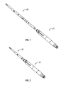
- Figure 1 shows a communication tool being run into the TRSSSV according to an exemplary embodiment of the present invention
- Figure 2 shows the communication tool of Figure 1 set and locked into the TRSSSV
- Figure 3 shows the communication tool of Figure 1 in the running mode
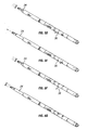
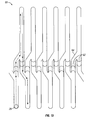
- Figures 6A-6C illustrate the indexing springs and indexing profiles of a communication tool according to an exemplary embodiment of the present invention
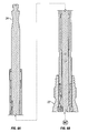
- Figure 7A shows a section view taken along the line A-A in Figure 7 ;
- Figure 7B is a section view taken along the line B-B in Figure 7 ;
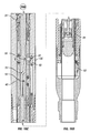
- Figures 8A-8D show a sectional view of an exemplary embodiment of the communication tool in the running position after it has landed in a TRSSSV;
- Figures 10A-10D show the communication tool of Figures 8A-8D in the full down jarring position
- Figure 13 illustrates the indexing profile according to an exemplary embodiment of the present invention.
- the central prong 24 is driven down into the communication tool 20 forcing the cutter 38 and reaction dog 40 to extend radially. If the cutter 38 makes contact with the exposed communication component 68 in the safety valve, hydraulic communication will be established. If the communication component 68 is not contacted, the central prong 24 and wireline weight bar (not shown) will be lifted until a fixed weight is registered. Upon pickup, the cutter housing 36 will rotate a fixed amount (e.g., 60°) positioning the cutter 38 for another radial cut on jarring.
- the terms indexing and rotating are used interchangeably to denote rotating the cutter 38 a fixed amount around the axis of the communication tool 20.
- the indexing of the cutter 38 is continued until the communication component 68 is penetrated and/or severed.
- the communication tool 20 is recovered by jarring up to sever the pulling shear pin 30 located within the lock piston assembly.
- the lock dogs 34, cutter 38 and reaction dogs 40 will all retract for pulling out of the well.
- Figure 7 illustrates the indexing springs 28 and the cutter system for an embodiment of the communication tool 20.
- Figure 7A shows a section view taken along the line A-A to illustrate the indexing springs 28.
- the indexing profile 60 ( Figure 13 ) on the outer diameter of the central prong 24 allow each of the indexing pins 29 on the plurality of index springs 28 to track in a mating groove, the shapes of which force the central prong 24 to rotate.
- Figure 7B is a section view taken along the line B-B in Figure 7 through the cutter system.
- the central prong 24 forces the extension pin 50 on the cutter 34 in and out radially during operation as will be discussed later.
- the reaction dog 34 is extended and retracted in the same manner.
- Figure 13 illustrates one exemplary embodiment of the indexing profiles 60 and an indexing pin 29 in movement therein.
- Ramps 62 and ledges 64 formed in the indexing profile 60 cause the central prong 24 to turn as the indexing pin 29 tracks through the indexing profile 60.
- those ordinarily skilled in the art having the benefit of this disclosure realize there are any number of ways to accomplish the indexing function of the present invention.
- FIGs 8A-8D illustrate an exemplary embodiment of communication tool 20 in the running position as it lands inside of the TRSSSV 22 in which communication is to be established.
- Central prong 24 extends longitudinally through the outer assembly of communication tool 20, the outer assembly including index housing 26, index springs 28, running shear pin 30 (shown intact) and lock body 32.
- the communication tool 20 is run inside of the production tubing and into the top of TRSSSV 22 until the lock dogs 30 are positioned adjacent to a mating profile in the safety valve hydraulic chamber housing.
- the cutter 38 is in the retracted position as illustrated in Figure 8C .
- the cutter 38 is adjacent a hydraulic chamber housing internal recess 67 which provides access to the upper end of the communication component 68.
- the communication component 68 is in communication with the piston bore 72 of the safety valve 22 via a communication retention ball 74.
- the retention ball 74 is press fitted inside of communication component 68, thereby retaining the component in the safety valve.
- the retention ball 74 includes an internal passageway 76 ( Figures 12B-C ) which provides communication between the communication component 68 and the piston bore 72.
- a hydraulic piston 78 is mounted inside a non-annular piston bore and connects to a flow tube 80.
- the flow tube 80 may be shifted via hydraulic pressure acting on the piston 78 to extend through a flapper 82 to open the safety valve. If hydraulic pressure is lost, a power spring 84 will force the flow tube 80 upwardly above the flapper 82 , thereby allowing the flapper 82 to pivot to the closed position and to prevent flow of well bore fluids up through the safety valve 22.
- the flow tube 80 is locked in the open position prior to the insertion of the communication tool 20.
- Various methods of locking open the TRSSSV 22 are known.
- the communication tool 20 is shown in the indexing position in Figures 9A-9D .
- the indexing position is a tool state when the central prong 24 is located under the lock dogs 34 effectively latching the tool 20 in the TRSSSV 22.
- the snap ring 47 on the lock piston 66 having expanded fully within the lower housing limiting any further upward motion from the central prong 24 (i.e., cannot come out from underneath the extended lock dogs).
- the operator must jar on the communication tool 20 to shear the pulling shear pin 46. Stroking up and down between this position and the full down position will cause the cutter housing and cutter 38 to rotate. When this action is continued, the cutter 38 will eventually extend into an exposed portion of the communication component 68.
- the full down jarring position for the communication tool 20 is illustrated in Figures 10A-10D .
- the full down position is a tool state that represents the full stroke limit of the communication tool 20.
- the slots 70 on the central prong 24 extend both the cutter 38 and the reaction dog 40 as extension pins 50 track slots 70. If the communication component 68 of the TRSSSV 22 is in front of a cutter 38, the jarring will sever the component 68 thus establishing hydraulic communication.
- the reaction dog 40 backs up the cutter 38 and takes radial play out of the tool 22.
- Figures 10C , 10E and 11E illustrate the communication component 68 being severed by the cutter 38.
- the recovery position of the communication tool 20 is illustrated in Figures 11A-D .
- the recovery position is when the central prong 24 has been jarred up such that the pulling shear pin 46 within the lock piston 66 is severed.
- the cutter 38, reaction dog 40 and locked dogs 30 all retract as extension pin 50 tracks down slots 70.
- the locked piston 66 will fall to the bottom of the lower housing. The tool will need to be redressed prior to any re-deployment.
- FIGS 12A-12C show one exemplary embodiment of the communication component 68 of the TRSSSV 22.
- Communication component 68 comprises a body 69 and a communication retention ball 74.
- the communication component body 69 is first installed into the hydraulic conduit within the TRSSSV hydraulic chamber housing. Sealing grooves 75 are provided on the lower end of the body 69.
- the retention ball 74 is pressed into the communication plug body 69, a high contact pressure, metal-to-metal seal between the sealing groves 75 of the body and the hydraulic conduit wall is established, effectively isolating the hydraulics from the inside of the TRSSSV 22.
- the communication component 68 is made of a frangible material that may be cut, pierced, sheared, punctured, or the like. During normal operations of the TRSSSV 22, the communication component is protected in the sidewall of the hydraulic chamber housing.
- body 69 is made of 718 Inconel or 625 stainless steel and ball 74 is made of 316 or 625 stainless steel. Please note, however, that one ordinarily skilled in the art having the benefit of this disclosure would realize any variety of communications components, chambers, etc. could be utilized within the scope of this invention.
- the communication tool 20 could be used to establish communication with other types of downhole devices (i.e., devices other than a TRSSSV). Such tools may, or may not, include a communication component through which fluid communication is established with the communication tool.
- the present invention is not limited to establishing communication with a TRSSSV but may be used to establish communication with other types of downhole devices. Accordingly, the invention is not to be restricted except in light of the attached claims and their equivalents.
Claims (18)
- Verbindungswerkzeug (20) zum Herstellen einer Fluidverbindung zwischen einer Steuerleitung und einer Bohrlocheinrichtung, das umfasst:ein Gehäuse (23, 36) mit einer hindurch verlaufenden Bohrung;einen mittigen Dorn (24), der sich in der Bohrung erstreckt, wobei der Dorn dazu ausgelegt ist, relativ zum Gehäuse nach oben oder nach unten betätigt zu werden; undeine Schneideinrichtung (38), die längs des Gehäuses angeordnet ist; dadurch gekennzeichnet, dassein Indexierungssystem (26, 28, 29, 60) in dem Gehäuse dazu ausgelegt ist, die Schneideinrichtung um die Achse des Verbindungswerkzeugs zu indexieren, um dadurch zu ermöglichen, dass die Schneideinrichtung an verschiedenen Punkten auf einer 360°-Ebene schneiden kann, wobei das Indexierungssystem auf die Betätigung des mittigen Dorns anspricht.
- Werkzeug nach Anspruch 1, wobei das Indexierungssystem umfasst:ein Indexierungsprofil (60) längs einer äußeren Oberfläche des mittigen Dorns; undmehrere Indexierungsstifte (29), die dem Indexierungsprofil folgen, wodurch bewirkt wird, dass der mittige Dorn die Schneideinrichtung um die Achse des Verbindungswerkzeugs indexiert.
- Werkzeug nach Anspruch 1 oder 2, wobei der mittige Dorn ein inneres Profil (70) aufweist, das verwendet wird, um zu veranlassen, dass die Schneideinrichtung in das Gehäuse zurückgezogen wird oder aus dem Gehäuse ausgefahren wird.
- Verfahren zum Herstellen einer Fluidverbindung mit einer Bohrlocheinrichtung, wobei das Verfahren die folgenden Schritte umfasst:(a) Einsetzen eines Verbindungswerkzeugs (20) in die Bohrlocheinrichtung, wobei das Verbindungswerkzeug eine Schneideinrichtung (38) längs eines Gehäuses (36) des Verbindungswerkzeugs aufweist, wobei die Schneideinrichtung dazu ausgelegt ist, an verschiedenen Punkten längs einer 360°-Ebene zu schneiden;(b) Ausfahren der Schneideinrichtung aus dem Gehäuse des Verbindungswerkzeugs; und(c) Abtrennen einer Verbindungskomponente der Bohrlocheinrichtung unter Verwendung der ausgefahrenen Schneideinrichtung, wobei die Verbindungskomponente in ein Gehäuse der Bohrlocheinrichtung angrenzend an eine Bohrung der Bohrlocheinrichtung eingesetzt wird.
- Verfahren nach Anspruch 4, wobei der Schritt (a) ferner den Schritt zum Verriegeln des Verbindungswerkzeugs in einer ausgewählten Position in der Bohrlocheinrichtung umfasst.
- Verfahren nach einem der Ansprüche 4 oder 5, wobei der Schritt (b) durch Betätigen eines Dorns (24) an dem Verbindungswerkzeug nach unten ausgeführt wird.
- Verfahren nach einem der Ansprüche 4 bis 6, wobei der Schritt (b) ferner den Schritt zum Indexieren der ausgefahrenen Schneideinrichtung um eine Achse des Verbindungswerkzeugs umfasst.
- Verfahren nach Anspruch 7, wobei das Indexieren durch Betätigen eines Dorns (24) der Verbindungseinrichtung nach oben ausgeführt wird.
- Verfahren nach Anspruch 8, ferner umfassend den Schritt zum wiederholten Betätigen des Dorns der Verbindungseinrichtung nach oben, wobei jede Betätigung nach oben die ausgefahrene Schneideinrichtung um 45° indexiert.
- Verfahren nach einem der Ansprüche 4 bis 9, ferner umfassend die Schritte zum Einziehen der ausgefahrenen Schneideinrichtung in das Gehäuse des Verbindungswerkzeugs und zum Entfernen des Verbindungswerkzeugs aus der Bohrlocheimrichtung.
- Verfahren nach einem der Ansprüche 4 bis 10, wobei die Schneideinrichtung radial aus dem Gehäuse des Verbindungswerkzeugs ausgefahren wird.
- Verfahren nach einem der Ansprüche 4 bis 11, wobei das Verfahren ferner die folgenden Schritte umfasst: Einsetzen eines WRSSSV (eines drahtgebundenen wiedergewinnbaren Untertage-Sicherheitsventils) in die Bohrlocheinrichtung; und Verbinden mit dem WRSSSV über die abgetrennte Verbindungskomponente der Bohrlocheinrichtung.
- Verfahren nach Anspruch 12, wobei der Schritt zum Verbinden mit dem WRSSSV die folgenden Schritte umfasst:Leiten von Fluid durch eine Kontrollleitung und in einen Hydraulikkanal, der mit der abgetrennten Verbindungskomponente in Verbindung steht;Leiten des Fluids von dem Hydraulikkanal durch die abgetrennte Verbindungskomponente; undLeiten des Fluids in das WRSSSV.
- Verfahren zum Herstellen einer Fluidverbindung mit einer ersten Bohrlocheinrichtung, wobei das Verfahren die folgenden aufeinander folgenden Schritte umfasst:(a) Einsetzen eines Verbindungswerkzeugs (20) in die erste Bohrlocheinrichtung (22), wobei das Verbindungswerkzeug eine Schneideinrichtung (38) längs eines Gehäuses (36) des Verbindungswerkzeugs aufweist;(b) Ausfahren der Schneideinrichtung aus dem Gehäuse des Verbindungswerkzeugs;(c) Zurückziehen der Schneideinrichtung;(d) Indexieren der zurückgezogenen Schneideinrichtung um eine Achse des Verbindungswerkzeugs;(e) Ausfahren der Schneideinrichtung aus dem Gehäuse des Verbindungswerkzeugs; und(f) Abtrennen einer Verbindungskomponente der ersten Bohrlocheinrichtung
- Verfahren nach Anspruch 14, wobei die Schritte (b) bis (e) durch Betätigen eines Dorns (24) des Verbindungswerkzeugs ausgeführt werden.
- Verfahren nach Anspruch 14 oder 15, das ferner die folgenden Schritte umfasst:Entfernen des Verbindungswerkzeugs aus der ersten Bohrlocheinrichtung;Einsetzen einer zweiten Bohrlocheinrichtung in die erste Bohrlocheinrichtung; undVerbinden mit der zweiten Bohrlocheinrichtung über die abgetrennte Verbindungskomponente der ersten Bohrlocheinrichtung.
- Verfahren nach Anspruch 16, wobei der Schritt zum Verbinden mit der zweiten Verbindungskomponente die folgenden Schritte umfasst:Leiten von Fluid in eine Steuerleitung, die mit der abgetrennten Verbindungskomponente in Verbindung steht, wobei die abgetrennte Verbindungskomponente in ein Gehäuse der ersten Bohrlocheinrichtung angrenzend an eine Bohrung der ersten Bohrlocheinrichtung eingesetzt wird;Leiten des Fluids von der Steuerleitung und durch die abgetrennte Verbindungskomponente, wobei das Fluid durch eine Rückhaltekugel, die in der abgetrennten Verbindungskomponente angeordnet ist, strömt; undLeiten des Fluids in die zweite Bohrlocheinrichtung.
- Verfahren nach einem der Ansprüche 14 bis 17, wobei sich die Schneideinrichtung radial von dem Gehäuse des Verbindungswerkzeugs erstreckt.
Applications Claiming Priority (2)
| Application Number | Priority Date | Filing Date | Title |
|---|---|---|---|
| US90122507P | 2007-02-13 | 2007-02-13 | |
| PCT/US2008/053863 WO2008101020A1 (en) | 2007-02-13 | 2008-02-13 | Communication tool for subsurface safety valve |
Publications (2)
| Publication Number | Publication Date |
|---|---|
| EP2118439A1 EP2118439A1 (de) | 2009-11-18 |
| EP2118439B1 true EP2118439B1 (de) | 2012-01-11 |
Family
ID=39525382
Family Applications (1)
| Application Number | Title | Priority Date | Filing Date |
|---|---|---|---|
| EP08729774A Active EP2118439B1 (de) | 2007-02-13 | 2008-02-13 | Kommunikationswerkzeug für ein sicherheitsventil unterhalb der oberfläche |
Country Status (7)
| Country | Link |
|---|---|
| US (1) | US7918280B2 (de) |
| EP (1) | EP2118439B1 (de) |
| AT (1) | ATE541109T1 (de) |
| AU (1) | AU2008216268B2 (de) |
| BR (1) | BRPI0807531B1 (de) |
| MY (1) | MY147882A (de) |
| WO (1) | WO2008101020A1 (de) |
Families Citing this family (13)
| Publication number | Priority date | Publication date | Assignee | Title |
|---|---|---|---|---|
| WO2013133784A1 (en) * | 2012-02-06 | 2013-09-12 | Halliburton Energy Services, Inc. | Exercising a well tool |
| US9523260B2 (en) | 2012-04-27 | 2016-12-20 | Tejas Research & Engineering, Llc | Dual barrier injection valve |
| US10704361B2 (en) | 2012-04-27 | 2020-07-07 | Tejas Research & Engineering, Llc | Method and apparatus for injecting fluid into spaced injection zones in an oil/gas well |
| US9334709B2 (en) | 2012-04-27 | 2016-05-10 | Tejas Research & Engineering, Llc | Tubing retrievable injection valve assembly |
| US8978775B2 (en) | 2012-11-28 | 2015-03-17 | Halliburton Energy Services, Inc. | Downhole valve assembly and methods of using the same |
| CN105518248B (zh) * | 2013-07-05 | 2019-09-24 | 布鲁斯·A.·通盖特 | 用于培养井下表面的设备和方法 |
| BR112018013854B1 (pt) | 2016-03-11 | 2022-12-13 | Halliburton Energy Services, Inc | Sub de diverter de desvio, sistema de poço, e, método |
| US10508512B2 (en) * | 2017-09-28 | 2019-12-17 | Baker Hughes, A Ge Company, Llc | Insert safety valve system |
| US10808478B2 (en) | 2018-02-14 | 2020-10-20 | Weatherford Technology Holdings, Llc | Assembly and method for performing aligned operation with tool oriented in downhole tubular |
| US10920529B2 (en) | 2018-12-13 | 2021-02-16 | Tejas Research & Engineering, Llc | Surface controlled wireline retrievable safety valve |
| WO2020056488A1 (en) * | 2018-09-19 | 2020-03-26 | Intelligent Wellhead Systems Inc. | Apparatus, system and process for regulating a control mechanism of a well |
| CN109339738A (zh) * | 2018-11-23 | 2019-02-15 | 东营市昌瑞石油机械配件有限责任公司 | 液压换层用轨道开关 |
| US11661826B2 (en) * | 2021-04-28 | 2023-05-30 | Halliburton Energy Services, Inc. | Well flow control using delayed secondary safety valve |
Family Cites Families (28)
| Publication number | Priority date | Publication date | Assignee | Title |
|---|---|---|---|---|
| US1801424A (en) * | 1928-09-11 | 1931-04-21 | Gray Tool Co | Inside casing cutter |
| US2457277A (en) * | 1941-08-01 | 1948-12-28 | Schlumberger Marcel | Well conditioning apparatus |
| US2322695A (en) * | 1942-05-11 | 1943-06-22 | Robert B Kinzbach | Pipe milling device |
| US3799258A (en) | 1971-11-19 | 1974-03-26 | Camco Inc | Subsurface well safety valve |
| US5197540A (en) * | 1987-04-14 | 1993-03-30 | Ashimori Kogyo Kabushiki Kaisha | Boring device for lining material in branched portions of lined conduit |
| US4981177A (en) | 1989-10-17 | 1991-01-01 | Baker Hughes Incorporated | Method and apparatus for establishing communication with a downhole portion of a control fluid pipe |
| US4944351A (en) | 1989-10-26 | 1990-07-31 | Baker Hughes Incorporated | Downhole safety valve for subterranean well and method |
| US5127476A (en) | 1991-05-10 | 1992-07-07 | Jerry L. Wilson | Lockout housing and sleeve for safety valve |
| US5201817A (en) | 1991-12-27 | 1993-04-13 | Hailey Charles D | Downhole cutting tool |
| US5249630A (en) | 1992-01-21 | 1993-10-05 | Otis Engineering Corporation | Perforating type lockout tool |
| US5226483A (en) | 1992-03-04 | 1993-07-13 | Otis Engineering Corporation | Safety valve landing nipple and method |
| US5496044A (en) | 1993-03-24 | 1996-03-05 | Baker Hughes Incorporated | Annular chamber seal |
| US5564675A (en) | 1994-10-19 | 1996-10-15 | Camco International Inc. | Subsurface safety valve of minimized length |
| US5598864A (en) | 1994-10-19 | 1997-02-04 | Camco International Inc. | Subsurface safety valve |
| US5690170A (en) * | 1996-02-22 | 1997-11-25 | Hailey; Charles D. | Hydraulic cutting overshot |
| US6155150A (en) * | 1998-07-29 | 2000-12-05 | Baker Hughes Incorporated | Hydraulic tubing punch and method of use |
| US6289999B1 (en) * | 1998-10-30 | 2001-09-18 | Smith International, Inc. | Fluid flow control devices and methods for selective actuation of valves and hydraulic drilling tools |
| US6352118B1 (en) | 2000-03-30 | 2002-03-05 | Halliburton Energy Services, Inc. | System and method for communication hydraulic control to a wireline retrievable downhole device |
| GB2373266B (en) | 2001-03-13 | 2004-08-18 | Sondex Ltd | Apparatus for anchoring a tool within a tubular |
| US6523614B2 (en) | 2001-04-19 | 2003-02-25 | Halliburton Energy Services, Inc. | Subsurface safety valve lock out and communication tool and method for use of the same |
| GB2390106B (en) | 2002-06-24 | 2005-11-30 | Schlumberger Holdings | Apparatus and methods for establishing secondary hydraulics in a downhole tool |
| US7188674B2 (en) * | 2002-09-05 | 2007-03-13 | Weatherford/Lamb, Inc. | Downhole milling machine and method of use |
| US7137452B2 (en) * | 2002-09-25 | 2006-11-21 | Baker Hughes Incorporated | Method of disabling and locking open a safety valve with releasable flow tube for flapper lockout |
| US6902006B2 (en) * | 2002-10-03 | 2005-06-07 | Baker Hughes Incorporated | Lock open and control system access apparatus and method for a downhole safety valve |
| US8016035B2 (en) | 2003-10-27 | 2011-09-13 | Baker Hughes Incorporated | Chemical injection check valve incorporated into a tubing retrievable safety valve |
| CA2636887C (en) | 2003-10-27 | 2012-03-13 | Baker Hughes Incorporated | Tubing retrievable safety valve and method |
| US20090126936A1 (en) * | 2003-11-05 | 2009-05-21 | Drilling Solutions Pty Ltd | Actuating mechanism |
| US20050153139A1 (en) * | 2004-01-12 | 2005-07-14 | Levitt Mark D. | Aqueous polyurethane coating system containing zinc crosslinked acrylic dispersion |
-
2008
- 2008-02-13 AU AU2008216268A patent/AU2008216268B2/en active Active
- 2008-02-13 AT AT08729774T patent/ATE541109T1/de active
- 2008-02-13 MY MYPI20093358A patent/MY147882A/en unknown
- 2008-02-13 BR BRPI0807531-0A patent/BRPI0807531B1/pt active IP Right Grant
- 2008-02-13 WO PCT/US2008/053863 patent/WO2008101020A1/en active Search and Examination
- 2008-02-13 US US12/030,725 patent/US7918280B2/en active Active
- 2008-02-13 EP EP08729774A patent/EP2118439B1/de active Active
Also Published As
| Publication number | Publication date |
|---|---|
| ATE541109T1 (de) | 2012-01-15 |
| EP2118439A1 (de) | 2009-11-18 |
| MY147882A (en) | 2013-01-31 |
| WO2008101020A1 (en) | 2008-08-21 |
| BRPI0807531A2 (pt) | 2014-06-10 |
| US20080190623A1 (en) | 2008-08-14 |
| AU2008216268A1 (en) | 2008-08-21 |
| US7918280B2 (en) | 2011-04-05 |
| BRPI0807531B1 (pt) | 2018-06-12 |
| AU2008216268B2 (en) | 2011-09-22 |
Similar Documents
| Publication | Publication Date | Title |
|---|---|---|
| EP2118439B1 (de) | Kommunikationswerkzeug für ein sicherheitsventil unterhalb der oberfläche | |
| EP1640558B1 (de) | Durch ein drahtseil herausziehbares sicherheitsventil mit radialem schneidwerkzeug | |
| EP2122119B1 (de) | Werkzeug und verfahren zur herstellung einer hydraulischen kommunikation mit einem unterirdischen sicherheitsventil | |
| US4903775A (en) | Well surging method and apparatus with mechanical actuating backup | |
| EP3652409B1 (de) | Bohrlochwerkzeug zum öffnen und schliessen einer fluidbohrung in einem bohrloch | |
| EP2103776B1 (de) | System und Verfahren zum wahlweisen Betrieb eines hydraulischen Nippel | |
| WO2011137112A2 (en) | Downhole barrier device | |
| CA2443140C (en) | Internal pressure indicator and locking mechanism for a downhole tool | |
| GB2339226A (en) | Wellbore formation isolation valve assembly | |
| RU2805204C2 (ru) | Объединенное фрезерное и добычное устройство и способ фрезерования и добычи текучей среды из ствола скважины |
Legal Events
| Date | Code | Title | Description |
|---|---|---|---|
| PUAI | Public reference made under article 153(3) epc to a published international application that has entered the european phase |
Free format text: ORIGINAL CODE: 0009012 |
|
| 17P | Request for examination filed |
Effective date: 20090807 |
|
| AK | Designated contracting states |
Kind code of ref document: A1 Designated state(s): AT BE BG CH CY CZ DE DK EE ES FI FR GB GR HR HU IE IS IT LI LT LU LV MC MT NL NO PL PT RO SE SI SK TR |
|
| RIN1 | Information on inventor provided before grant (corrected) |
Inventor name: BAHR, GLENN, A. Inventor name: MAILAND, JASON, C. |
|
| DAX | Request for extension of the european patent (deleted) | ||
| 17Q | First examination report despatched |
Effective date: 20100706 |
|
| GRAP | Despatch of communication of intention to grant a patent |
Free format text: ORIGINAL CODE: EPIDOSNIGR1 |
|
| GRAS | Grant fee paid |
Free format text: ORIGINAL CODE: EPIDOSNIGR3 |
|
| GRAA | (expected) grant |
Free format text: ORIGINAL CODE: 0009210 |
|
| AK | Designated contracting states |
Kind code of ref document: B1 Designated state(s): AT BE BG CH CY CZ DE DK EE ES FI FR GB GR HR HU IE IS IT LI LT LU LV MC MT NL NO PL PT RO SE SI SK TR |
|
| REG | Reference to a national code |
Ref country code: GB Ref legal event code: FG4D |
|
| REG | Reference to a national code |
Ref country code: CH Ref legal event code: EP |
|
| REG | Reference to a national code |
Ref country code: AT Ref legal event code: REF Ref document number: 541109 Country of ref document: AT Kind code of ref document: T Effective date: 20120115 |
|
| REG | Reference to a national code |
Ref country code: IE Ref legal event code: FG4D |
|
| REG | Reference to a national code |
Ref country code: DE Ref legal event code: R096 Ref document number: 602008012663 Country of ref document: DE Effective date: 20120308 |
|
| REG | Reference to a national code |
Ref country code: NL Ref legal event code: VDEP Effective date: 20120111 |
|
| RAP2 | Party data changed (patent owner data changed or rights of a patent transferred) |
Owner name: BAKER HUGHES INCORPORATED |
|
| PG25 | Lapsed in a contracting state [announced via postgrant information from national office to epo] |
Ref country code: SI Free format text: LAPSE BECAUSE OF FAILURE TO SUBMIT A TRANSLATION OF THE DESCRIPTION OR TO PAY THE FEE WITHIN THE PRESCRIBED TIME-LIMIT Effective date: 20120111 |
|
| LTIE | Lt: invalidation of european patent or patent extension |
Effective date: 20120111 |
|
| REG | Reference to a national code |
Ref country code: GB Ref legal event code: 732E Free format text: REGISTERED BETWEEN 20120607 AND 20120613 |
|
| PG25 | Lapsed in a contracting state [announced via postgrant information from national office to epo] |
Ref country code: NO Free format text: LAPSE BECAUSE OF FAILURE TO SUBMIT A TRANSLATION OF THE DESCRIPTION OR TO PAY THE FEE WITHIN THE PRESCRIBED TIME-LIMIT Effective date: 20120411 Ref country code: BE Free format text: LAPSE BECAUSE OF FAILURE TO SUBMIT A TRANSLATION OF THE DESCRIPTION OR TO PAY THE FEE WITHIN THE PRESCRIBED TIME-LIMIT Effective date: 20120111 Ref country code: BG Free format text: LAPSE BECAUSE OF FAILURE TO SUBMIT A TRANSLATION OF THE DESCRIPTION OR TO PAY THE FEE WITHIN THE PRESCRIBED TIME-LIMIT Effective date: 20120411 Ref country code: LT Free format text: LAPSE BECAUSE OF FAILURE TO SUBMIT A TRANSLATION OF THE DESCRIPTION OR TO PAY THE FEE WITHIN THE PRESCRIBED TIME-LIMIT Effective date: 20120111 Ref country code: IS Free format text: LAPSE BECAUSE OF FAILURE TO SUBMIT A TRANSLATION OF THE DESCRIPTION OR TO PAY THE FEE WITHIN THE PRESCRIBED TIME-LIMIT Effective date: 20120511 Ref country code: NL Free format text: LAPSE BECAUSE OF FAILURE TO SUBMIT A TRANSLATION OF THE DESCRIPTION OR TO PAY THE FEE WITHIN THE PRESCRIBED TIME-LIMIT Effective date: 20120111 Ref country code: HR Free format text: LAPSE BECAUSE OF FAILURE TO SUBMIT A TRANSLATION OF THE DESCRIPTION OR TO PAY THE FEE WITHIN THE PRESCRIBED TIME-LIMIT Effective date: 20120111 |
|
| PG25 | Lapsed in a contracting state [announced via postgrant information from national office to epo] |
Ref country code: LV Free format text: LAPSE BECAUSE OF FAILURE TO SUBMIT A TRANSLATION OF THE DESCRIPTION OR TO PAY THE FEE WITHIN THE PRESCRIBED TIME-LIMIT Effective date: 20120111 Ref country code: GR Free format text: LAPSE BECAUSE OF FAILURE TO SUBMIT A TRANSLATION OF THE DESCRIPTION OR TO PAY THE FEE WITHIN THE PRESCRIBED TIME-LIMIT Effective date: 20120412 Ref country code: PL Free format text: LAPSE BECAUSE OF FAILURE TO SUBMIT A TRANSLATION OF THE DESCRIPTION OR TO PAY THE FEE WITHIN THE PRESCRIBED TIME-LIMIT Effective date: 20120111 Ref country code: PT Free format text: LAPSE BECAUSE OF FAILURE TO SUBMIT A TRANSLATION OF THE DESCRIPTION OR TO PAY THE FEE WITHIN THE PRESCRIBED TIME-LIMIT Effective date: 20120511 Ref country code: FI Free format text: LAPSE BECAUSE OF FAILURE TO SUBMIT A TRANSLATION OF THE DESCRIPTION OR TO PAY THE FEE WITHIN THE PRESCRIBED TIME-LIMIT Effective date: 20120111 |
|
| REG | Reference to a national code |
Ref country code: AT Ref legal event code: MK05 Ref document number: 541109 Country of ref document: AT Kind code of ref document: T Effective date: 20120111 |
|
| PG25 | Lapsed in a contracting state [announced via postgrant information from national office to epo] |
Ref country code: CY Free format text: LAPSE BECAUSE OF FAILURE TO SUBMIT A TRANSLATION OF THE DESCRIPTION OR TO PAY THE FEE WITHIN THE PRESCRIBED TIME-LIMIT Effective date: 20120111 Ref country code: MC Free format text: LAPSE BECAUSE OF NON-PAYMENT OF DUE FEES Effective date: 20120229 |
|
| REG | Reference to a national code |
Ref country code: CH Ref legal event code: PL |
|
| PG25 | Lapsed in a contracting state [announced via postgrant information from national office to epo] |
Ref country code: SE Free format text: LAPSE BECAUSE OF FAILURE TO SUBMIT A TRANSLATION OF THE DESCRIPTION OR TO PAY THE FEE WITHIN THE PRESCRIBED TIME-LIMIT Effective date: 20120111 Ref country code: CH Free format text: LAPSE BECAUSE OF NON-PAYMENT OF DUE FEES Effective date: 20120229 Ref country code: CZ Free format text: LAPSE BECAUSE OF FAILURE TO SUBMIT A TRANSLATION OF THE DESCRIPTION OR TO PAY THE FEE WITHIN THE PRESCRIBED TIME-LIMIT Effective date: 20120111 Ref country code: EE Free format text: LAPSE BECAUSE OF FAILURE TO SUBMIT A TRANSLATION OF THE DESCRIPTION OR TO PAY THE FEE WITHIN THE PRESCRIBED TIME-LIMIT Effective date: 20120111 Ref country code: RO Free format text: LAPSE BECAUSE OF FAILURE TO SUBMIT A TRANSLATION OF THE DESCRIPTION OR TO PAY THE FEE WITHIN THE PRESCRIBED TIME-LIMIT Effective date: 20120111 Ref country code: LI Free format text: LAPSE BECAUSE OF NON-PAYMENT OF DUE FEES Effective date: 20120229 Ref country code: DK Free format text: LAPSE BECAUSE OF FAILURE TO SUBMIT A TRANSLATION OF THE DESCRIPTION OR TO PAY THE FEE WITHIN THE PRESCRIBED TIME-LIMIT Effective date: 20120111 |
|
| PLBE | No opposition filed within time limit |
Free format text: ORIGINAL CODE: 0009261 |
|
| STAA | Information on the status of an ep patent application or granted ep patent |
Free format text: STATUS: NO OPPOSITION FILED WITHIN TIME LIMIT |
|
| REG | Reference to a national code |
Ref country code: IE Ref legal event code: MM4A |
|
| PG25 | Lapsed in a contracting state [announced via postgrant information from national office to epo] |
Ref country code: SK Free format text: LAPSE BECAUSE OF FAILURE TO SUBMIT A TRANSLATION OF THE DESCRIPTION OR TO PAY THE FEE WITHIN THE PRESCRIBED TIME-LIMIT Effective date: 20120111 Ref country code: IT Free format text: LAPSE BECAUSE OF FAILURE TO SUBMIT A TRANSLATION OF THE DESCRIPTION OR TO PAY THE FEE WITHIN THE PRESCRIBED TIME-LIMIT Effective date: 20120111 |
|
| REG | Reference to a national code |
Ref country code: DE Ref legal event code: R119 Ref document number: 602008012663 Country of ref document: DE Effective date: 20120901 |
|
| 26N | No opposition filed |
Effective date: 20121012 |
|
| PG25 | Lapsed in a contracting state [announced via postgrant information from national office to epo] |
Ref country code: IE Free format text: LAPSE BECAUSE OF NON-PAYMENT OF DUE FEES Effective date: 20120213 Ref country code: AT Free format text: LAPSE BECAUSE OF FAILURE TO SUBMIT A TRANSLATION OF THE DESCRIPTION OR TO PAY THE FEE WITHIN THE PRESCRIBED TIME-LIMIT Effective date: 20120111 |
|
| PG25 | Lapsed in a contracting state [announced via postgrant information from national office to epo] |
Ref country code: ES Free format text: LAPSE BECAUSE OF FAILURE TO SUBMIT A TRANSLATION OF THE DESCRIPTION OR TO PAY THE FEE WITHIN THE PRESCRIBED TIME-LIMIT Effective date: 20120422 |
|
| PG25 | Lapsed in a contracting state [announced via postgrant information from national office to epo] |
Ref country code: DE Free format text: LAPSE BECAUSE OF NON-PAYMENT OF DUE FEES Effective date: 20120901 |
|
| PG25 | Lapsed in a contracting state [announced via postgrant information from national office to epo] |
Ref country code: MT Free format text: LAPSE BECAUSE OF FAILURE TO SUBMIT A TRANSLATION OF THE DESCRIPTION OR TO PAY THE FEE WITHIN THE PRESCRIBED TIME-LIMIT Effective date: 20120111 |
|
| PG25 | Lapsed in a contracting state [announced via postgrant information from national office to epo] |
Ref country code: TR Free format text: LAPSE BECAUSE OF FAILURE TO SUBMIT A TRANSLATION OF THE DESCRIPTION OR TO PAY THE FEE WITHIN THE PRESCRIBED TIME-LIMIT Effective date: 20120111 |
|
| PG25 | Lapsed in a contracting state [announced via postgrant information from national office to epo] |
Ref country code: LU Free format text: LAPSE BECAUSE OF NON-PAYMENT OF DUE FEES Effective date: 20120213 |
|
| PG25 | Lapsed in a contracting state [announced via postgrant information from national office to epo] |
Ref country code: HU Free format text: LAPSE BECAUSE OF FAILURE TO SUBMIT A TRANSLATION OF THE DESCRIPTION OR TO PAY THE FEE WITHIN THE PRESCRIBED TIME-LIMIT Effective date: 20080213 |
|
| REG | Reference to a national code |
Ref country code: FR Ref legal event code: PLFP Year of fee payment: 8 |
|
| REG | Reference to a national code |
Ref country code: FR Ref legal event code: PLFP Year of fee payment: 9 |
|
| REG | Reference to a national code |
Ref country code: FR Ref legal event code: PLFP Year of fee payment: 10 |
|
| REG | Reference to a national code |
Ref country code: FR Ref legal event code: PLFP Year of fee payment: 11 |
|
| PGFP | Annual fee paid to national office [announced via postgrant information from national office to epo] |
Ref country code: FR Payment date: 20230119 Year of fee payment: 16 |
|
| P01 | Opt-out of the competence of the unified patent court (upc) registered |
Effective date: 20230526 |
|
| PGFP | Annual fee paid to national office [announced via postgrant information from national office to epo] |
Ref country code: GB Payment date: 20240123 Year of fee payment: 17 |