EP2118434B1 - Apparatus for rock drilling - Google Patents
Apparatus for rock drilling Download PDFInfo
- Publication number
- EP2118434B1 EP2118434B1 EP08705223.9A EP08705223A EP2118434B1 EP 2118434 B1 EP2118434 B1 EP 2118434B1 EP 08705223 A EP08705223 A EP 08705223A EP 2118434 B1 EP2118434 B1 EP 2118434B1
- Authority
- EP
- European Patent Office
- Prior art keywords
- space
- rinsing device
- mantle surface
- neck adaptor
- rinse head
- Prior art date
- Legal status (The legal status is an assumption and is not a legal conclusion. Google has not performed a legal analysis and makes no representation as to the accuracy of the status listed.)
- Active
Links
Images


Classifications
-
- E—FIXED CONSTRUCTIONS
- E21—EARTH OR ROCK DRILLING; MINING
- E21B—EARTH OR ROCK DRILLING; OBTAINING OIL, GAS, WATER, SOLUBLE OR MELTABLE MATERIALS OR A SLURRY OF MINERALS FROM WELLS
- E21B6/00—Drives for drilling with combined rotary and percussive action
-
- E—FIXED CONSTRUCTIONS
- E21—EARTH OR ROCK DRILLING; MINING
- E21B—EARTH OR ROCK DRILLING; OBTAINING OIL, GAS, WATER, SOLUBLE OR MELTABLE MATERIALS OR A SLURRY OF MINERALS FROM WELLS
- E21B17/00—Drilling rods or pipes; Flexible drill strings; Kellies; Drill collars; Sucker rods; Cables; Casings; Tubings
- E21B17/02—Couplings; joints
- E21B17/03—Couplings; joints between drilling rod or pipe and drill motor or surface drive, e.g. between drilling rod and hammer
-
- E—FIXED CONSTRUCTIONS
- E21—EARTH OR ROCK DRILLING; MINING
- E21B—EARTH OR ROCK DRILLING; OBTAINING OIL, GAS, WATER, SOLUBLE OR MELTABLE MATERIALS OR A SLURRY OF MINERALS FROM WELLS
- E21B21/00—Methods or apparatus for flushing boreholes, e.g. by use of exhaust air from motor
- E21B21/02—Swivel joints in hose-lines
Definitions
- the present invention concerns a rinsing device for a drill for rock drilling, as well as a drilling device comprising a rinsing device.
- the invention concerns lubrication of sealing elements in the rinsing device.
- a typical example of a rock drill comprises a number of drilling rods which are joined together and form a drill string.
- One end of the drill string culminates in a drill head which drills into the stone as it cuts and rotates.
- the other end of the drill rod is coupled to a drive apparatus via a neck adaptor. In use, the drill string cuts and rotates by means of the drive apparatus.
- a rinsing medium e.g. water or air
- Drill cuttings mixed with the rinsing medium are then forced out of the drill hole between the drilling rod and the walls of the drill hole.
- the neck adaptor is sealed against the rinse head by means of rinse seals.
- the neck adaptor has a rotating to-and-fro movement, while the rinse head is stationary relative to the drill.
- rinse seals are often doubled both forward and backward and have one or more so-called "spyhole” so that the operator is given the chance to notice a leak and replace the primary seal before the secondary seal also fails. In this way, the rinsing medium is prevented from entering the drill, which prevents damage to the drill.
- the current lifetime of rinse seals can be seen as a problem. Damaged rinse seals are a common reason why drills need to be serviced.
- the front bearing of the neck adaptor is stationary relative to the drill.
- an air-oil mixture is used, which has been the tradition since pneumatic drills.
- oil was added to the pressurized gas which drove the striking apparatus and rinsed away drill cuttings.
- Lubricating gas in hydraulic drills comprises an entire system which branches to many places in the drill. This is partly due to the requirement for lubrication in many places, but also - by means of overpressure - to prevent drill cuttings from entering the drill.
- One aim of the present invention is therefore to provide a rinsing device for a drilling device which improves the lifetime of the rinse seals in the rinsing device.
- a rinsing device for a drilling device for rock drilling.
- the rinsing device comprises a cylindrical neck adaptor which comprises a mantle surface, two end surfaces, a central axial passage which opens at one end surface, and a radial connection between the central axial passage and an opening in the mantle surface.
- the rinsing device also comprises a rinse head with a axially-extending hole.
- the neck adaptor is slidably arranged in said hole.
- the said rinse head surrounds a part of the mantle surface of the neck adaptor and provides a first space which extends around the mantle surface of the neck adaptor in the region of the opening in the mantle surface of the neck adaptor.
- the first space is connected to the outside of the rinse head via a feed channel.
- the rinsing device comprises at least one primary sealing element arranged in the axial direction on each side of the first space in the rinse head to provide a seal between the neck adaptor and the first space.
- the rinsing device also comprises at least one second space which extends about the mantle surface of the neck adaptor. Each of the second spaces borders that side of each primary sealing element which faces away from the first space.
- the rinsing device comprises means for supplying lubricant to the second space.
- the means for supplying lubricant to the second space comprises one or more outlets which extend from the second space to the outside of the rinse head.
- the rinsing device comprises means for supplying lubricant to the second space
- lubricant will be able to lubricate the contact between the neck adaptor and the sealing element. In this way, friction is lower and wear of the seal is reduced, which means that the lifetime of the sealing element is improved.
- One advantage of the present invention is that corrosion of the mantle surface of the neck adaptor is reduced, as it is not subjected to the moist air which can reach the mantle surface through the spyhole, which also contributes to an improved lifetime.
- Another advantage of the present invention is that water and dirt penetration into the drill via the lubricating gas system - and the damage resulting therefrom - is avoided.
- FIG. 1 shows a device for rock drilling 10.
- the rock drilling device 10 comprises a drill 20, a number of drilling rods 30 (only one is shown), which are joined together and form a drill string 40.
- One end of the drill string culminates in a drill head 50 which drills into the stone 52 as it cuts and rotates, thereby forming a drill hole 55.
- the other end of the drill rod is coupled to drill 20 via a neck adaptor 60.
- the drill string 40 cuts and with to-and-fro movements, and rotates in use, driven by the drill 20.
- the drill comprises a rinsing device 70.
- a rinsing medium e.g.
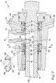
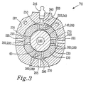
- FIG. 2 shows a side-view of a first example of the rinsing device 70 and Figure 3 shows a cross-section along the line III-III in Figure 2 of the first example of the rinsing device 70.
- the rinsing device 70 comprises a neck adaptor 60, said neck adaptor 60 being cylindrical and comprising a mantle surface 90, two end surfaces, a central axial passage 100 which opens at one end surface.
- the neck adaptor 60 also comprises a radial connection 110 between the central axial passage 100 and an opening 120 in the mantle surface 90.
- the rinsing medium is intended to be flushed into the neck adaptor 60 through opening 120, further through the radial connection 110 and into the central axial passage 100 for futher passage through the drill string 40 and drill head 50, and out through the drill head to the drill hole (as shown in Figure 1 ).
- the rinsing device 70 comprises a rinse head 130.
- An aim of the rinse head 130 is that it provides a replaceable holder for the sealing element (said sealing element is described in more detail below).
- the rinse head 130 comprises an axially extending hole 140, in which hole the neck adaptor 60 is slidably arranged, so that - during drilling - the neck adaptor can rotate and move forwards and backwards in the rinse head which is stationary relative to the drill 20.
- the rinse head 130 surrounds a part of the mantle surface 90 of the neck adaptor and provides a first space 150.
- the first space 150 extends around the mantle surface 90 of the neck adaptor in the region of the opening 120 in the mantle surface 90 of the neck adaptor.
- the first space 150 is connected to the outside of the rinse head 130 via a feed channel 160. This can for example be via a rinse adaptor 170.
- the first space 150 is preferably arranged so that the opening 120 of the neck adaptor is always located within the first space 150 upon rotating to-and-fro movement, which means that the rinsing medium always has free access to opening 120 in the mantle surface 90 of the neck adaptor.
- the rinsing device 70 comprises at least one primary sealing element 180.
- the primary sealing element 180 is arranged in the axial direction on each side of the first space 150 in the rinse head 130 to provide a seal between the neck adaptor 60 and the first space 150, to prevent rinse medium leaking from the first space 150 along the gap between the mantle surface 90 of the neck adaptor 60 and the rinse head 130. Should such a leakage for instance reach the drill, damage can occur.
- Certain embodiments, such as the example in Figure 2 comprise two primary sealing elements 180, wherein one is arranged on one side of the opening 120 in the neck adaptor, and the other is arranged on the other side of the neck adaptor's opening 120.
- the rinsing device 170 comprises at least one secondary sealing element 190 arranged in the axial direction on each side of the first space 150 in the rinse head 130 and on that side of each primary sealing element 180 which faces away from the first space 150, for a further seal between the neck adaptor 60 and the first space 150.
- Certain embodiments such as the example in Figure 2 , comprise two secondary sealing elements 190, whereby one is arranged on that side of one primary sealing element 180 which faces away from the first space 150, and the other is arranged on that side of the other primary sealing element 180 which faces away from the first space 150.
- the primary sealing elements 180 and the secondary sealing elements 190 can e.g. be unidirectional, such as e.g. so-called U-sleeves, i.e. in this case these should seal in the direction from the first space 150.
- the rinsing device 70 also comprises at least one second space 200 which extends about the mantle surface 90 of the neck adaptor, which second space 200 borders that face of each primary sealing element 180 which faces away from the first space.
- the rinsing device comprises two second spaces 200, each of said two second spaces 200 being arranged on each side of the first space 150.
- the rinsing device 70 comprises means for supplying lubricant to the second space 200. This is to lubricate the contact surfaces between the neck adaptor 60 (and in certain cases also the guide which is described in more detail below) and the primary sealing elements 180 and in certain cases, the secondary sealing elements 190, so that contact friction between the neck adaptor 60 and the primary and secondary sealing elements 180, 190 is reduced. This reduces wear on the primary and secondary sealing elements 180, 190.
- grease or another lubricant with high viscosity can be used as lubricant.
- the lubricant should not comprise lubricating gas.
- Grease can be defined as a solid, semi-liquid or hard product, which is obtained by introducing a thickening agent to a liquid lubricant.
- a special method is used according to EN-ISO 2137.
- the values measured are the depth in mm to which a special cone penetrates homogenized grease under 5 seconds at 25°C.
- the consistency is specified as penetration in 1/10mm.
- NGLI National Lubrication Grease Institute
- the means for supplying lubricant to the second space 200 comprises one or more inlets 210, said inlets 210 extending from the outside of the rinsing device 70 to the second space 200.
- the inlets 210 allow lubricant to be transferred from the outside of the rinsing device, e.g. via a grease nipple 215 to the second space 200.
- the inlet 210 extends radially to the mantle surface 90 of the neck adaptor in the second space 200.
- the inlet 210 can e.g.
- the inlet 210 can e.g. be formed as two or more channels 240, such as e.g. shown in Figure 3 , in which the inlet 210 is formed as two channels 240.
- the opening 220 of the inlet in the rinse head 130 is comprised in a recess 250 in the mantle surface 230 of the rinse head. This has the advantage that lubricant can more easily be distributed in the inlet 210 or channels 240 where these pass through the rinse head 130.
- the recess prevents lubricant from taking short-cuts along the outer mantle surface of the rinse head from the inlet 210 to the outlet 260 (as described below), without passing the neck adapter 60 and the second space 200.
- the means for supplying lubricant to the second space 200 comprises one or more outlets 260.
- the outlets extend from the second space 200 to the outside of the rinse head, and allow excess lubricant to pass out of the rinsing device 70, e.g. through so-called spyhole 265 in an outer cover 267 of the rinsing device 70.
- This also allows rinse medium to flow out if it has leaked past the primary and in certain cases secondary sealing elements 180, 190, which means that a user can see from the outside of the rinsing device 70 whether such a leak has occurred, so that the primary, and in certain cases, the secondary sealing elements 180, 190 can be replaced if they have worn out.
- the supply of lubricant increases the lifetime of the primary and in certain cases, secondary, sealing elements 180, 190.
- the lubricant does not prevent the passage of rinse medium through the spyhole 265, as the rinse medium has a certain pressure, and pushes out the lubricant.
- any lubricant present in the spyhole does prevent water and dirt entering from outside and penetrating the neck adaptor 60 and the primary and secondary sealing elements 180 and 190, where they would cause wear and corrosion.
- the outlet 260 extends radially from the mantle surface 90 of the neck adaptor in the second space 200.
- the outlet 260 can e.g. extend from the second space 200, through the rinse head 130 and to a vent 270 on the mantle surface 230 of the rinse head, such as e.g. shown in Figures 3 , 5 and 6 .
- each outlet 260 through the rinse head 130 comprises two or more channels 280 through the rinse head 130.
- the vent 270 of the outlet in the rinse head is comprised in a recess 290 in the mantle surface 90 of the rinse head.
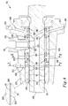
- Figure 4 shows a side-view of an embodiment of the rinsing device 70.
- Figure 5 shows a cross-section along the line V-V of the embodiment of Figure 4 , e.g. the cross-sections runs through a cylindrical guide 300.
- Figure 6 shows a cross-section along the line VI-VI of the embodiment of Figure 4 .
- the rinsing device comprises a guide 300, said guide 300 comprising an axially extending hole 310, the neck adaptor 60 being slidably arranged in said hole.
- the guide can e.g. be a so-called nose bush.
- the guide 300 surrounds a portion of the mantle surface 90 of the neck adaptor.
- the guide 300 borders the rinse head 130 and the second space 200.
- the inlet 210 extends through the guide 300 from an opening 320 on a mantle surface 330 of the guide 300 to the second space 200.
- the inlets 210 of certain embodiments can comprise two or more channels (not shown), to obtain an even better flow of lubricant to the second space 200.
- the inlet 210 runs through the guide 300 and the outlet 260 through the rinse head 130, this is shown in Figures 4 , 5 and 6 .
- the lubricant is squirted in via channels 240 through, e.g. the outer cover 267 of the rinsing device 70.
- the lubricant is carried further in through the inlet 210 to the second space 200, where it is allowed to spread.
- the second space 200 can e.g. be contained between the primary sealing elements 180 and the secondary sealing elements 190, as shown in Figure 2 . In this way, the lubricant can be supplied between the primary sealing element 180 and the secondary sealing element 190 to the second space 200.
- the second space 200 can also be contained on that face of each primary sealing element 180 which faces away from the first space 150, as shown in Figure 4 .
- Lubricant can therefore be supplied to the second space 200, on that face of each second sealing element which faces away from the first space 150. This requires that, when the lubricant reaches the secondary sealing element 190, and the secondary sealing element 190 is unidirectional, such as e.g. so-called U-sleeves, the secondary sealing element 190 releases and allows lubricant to enter into the space between the primary 180 and secondary 190 sealing elements.
- lubrication of the guide 300 is also made possible; in this case, the second space extends along the mantle surface of the neck adaptor 60 both in the region where it is surrounded by the rinse head 130 and where the neck adaptor 660 is surrounded by the guide 300. (This requires that the lubricant spreads both to the left and right in Figure 4 , when it is squirted in through the left grease nipple 215).
- This embodiment is very advantageous, as water and drill cuttings are prevented from entering via the lubricating gas pipes in the guide 300, as no lubricating gas pipes are required.
- lubricant is squirted in on that face of each primary sealing element 180 which faces away from the first space 150.
- the lubricant can e.g. be squirted in via inlet 210 in the rinse head 130 or via inlet 210 in the guide 300.
- the lubricant is then carried further out through the oulet 260.
- lubricant is seen e.g. in some of the spyholes 265 coupled to the outlet 206, filling with lubricant is complete.
- the variously described embodiments of the rinse head 130 and guide 300 are formed so that grease is forced all the way to the neck adaptor 60 before it can spread further out via the outlet 260 and the spyholes.
- the lubricant lubricates the contact between the neck adaptor 60 and the sealing elements 180, 190 and in certain embodiments, also between the neck adaptor 60 and the guide 300. In this way, friction is lowered and wear and heat production is lowered.
- the lubricant also reduces corrosion by preventing air from making contact with the neck adaptor 60. External water which enters via the rear entrance through the spyholes 265 is also prevented from reaching the neck adaptor 60 and in certain cases, the guide 300.
- the lubricant can e.g. be squirted in continuously or at close intervals, e.g. by manual injection through the grease nipple, by a central lubrication system from e.g. a drill rig in which the drill 20 is arranged, by a lubricant container on a sled on which the drill 20 is arranged, said lubricant container in turn may be pressurised by lubricating gas via a branched tube from a lubricating gas intake on the drill 20, or by an automated grease cartridge which is exchanged at regular intervals.
- a central lubrication system from e.g. a drill rig in which the drill 20 is arranged
- a lubricant container on a sled on which the drill 20 is arranged said lubricant container in turn may be pressurised by lubricating gas via a branched tube from a lubricating gas intake on the drill 20, or by an automated grease cartridge which is exchanged at regular intervals.
Landscapes
- Engineering & Computer Science (AREA)
- Life Sciences & Earth Sciences (AREA)
- Geology (AREA)
- Mining & Mineral Resources (AREA)
- Physics & Mathematics (AREA)
- Environmental & Geological Engineering (AREA)
- Fluid Mechanics (AREA)
- General Life Sciences & Earth Sciences (AREA)
- Geochemistry & Mineralogy (AREA)
- Mechanical Engineering (AREA)
- Earth Drilling (AREA)
Description
- The present invention concerns a rinsing device for a drill for rock drilling, as well as a drilling device comprising a rinsing device. In particular, the invention concerns lubrication of sealing elements in the rinsing device.
- A typical example of a rock drill comprises a number of drilling rods which are joined together and form a drill string. One end of the drill string culminates in a drill head which drills into the stone as it cuts and rotates. The other end of the drill rod is coupled to a drive apparatus via a neck adaptor. In use, the drill string cuts and rotates by means of the drive apparatus.
- In order that drilling can be carried out effectively when drilling stone, it is necessary that the bottom of the drill hole is kept clean and that drill cuttings are carried away from the drill hole. This is done by a rinsing medium, e.g. water or air, being flushed from a rinse adaptor via a rinse head in through, through a central hole in the neck adaptor, and further through a central hole in the drill string and out through the drill head to the bottom of the drill hole. Drill cuttings mixed with the rinsing medium are then forced out of the drill hole between the drilling rod and the walls of the drill hole.
- To prevent the rinsing medium from entering the drill, the neck adaptor is sealed against the rinse head by means of rinse seals. The neck adaptor has a rotating to-and-fro movement, while the rinse head is stationary relative to the drill.
- These rinse seals are often doubled both forward and backward and have one or more so-called "spyhole" so that the operator is given the chance to notice a leak and replace the primary seal before the secondary seal also fails. In this way, the rinsing medium is prevented from entering the drill, which prevents damage to the drill.
The current lifetime of rinse seals can be seen as a problem. Damaged rinse seals are a common reason why drills need to be serviced. - Mine environments with damp air, and occasionally saline rinse water are a particular problem. The surface of the neck adaptor quickly becomes corroded and the surface upon which the rinse seals must glide becomes highly wearing.
Additional problems are that the rinse seals become warm through contact friction, especially in high-frequency machines. The primary seals are effectively cooled by the rinse water, but the secondary seals are not always cooled, as the separate lubricating gas in the drill does not always reach the secondary seals. - The front bearing of the neck adaptor is stationary relative to the drill. Currently, to lubricate this contact surface, an air-oil mixture is used, which has been the tradition since pneumatic drills. In such drills, oil was added to the pressurized gas which drove the striking apparatus and rinsed away drill cuttings. When production and use of hydraulic drills began, it was desirable to maintain lubrication, which is why a separate lubricating gas flow was introduced.
Lubricating gas in hydraulic drills comprises an entire system which branches to many places in the drill. This is partly due to the requirement for lubrication in many places, but also - by means of overpressure - to prevent drill cuttings from entering the drill.
As the lubricating gas system branches off to the entire machine, water and dirt, as well as drill cuttings and particles ground from drilling parts and the like, are effectively spread to the entire machine, should the lubricating gas system be polluted.
The risk of such pollution, especially water penetration, is large at the front of the drill. Here, water can penetrate both from the outside by, e.g. a worn nose bush, or from the inside, by rinse water passing through a worn rinse seal. - One aim of the present invention is therefore to provide a rinsing device for a drilling device which improves the lifetime of the rinse seals in the rinsing device.
- In accordance with the present invention, this aim is achieved by a rinsing device for a drilling device for rock drilling. The rinsing device comprises a cylindrical neck adaptor which comprises a mantle surface, two end surfaces, a central axial passage which opens at one end surface, and a radial connection between the central axial passage and an opening in the mantle surface. The rinsing device also comprises a rinse head with a axially-extending hole. The neck adaptor is slidably arranged in said hole. The said rinse head surrounds a part of the mantle surface of the neck adaptor and provides a first space which extends around the mantle surface of the neck adaptor in the region of the opening in the mantle surface of the neck adaptor. The first space is connected to the outside of the rinse head via a feed channel. The rinsing device comprises at least one primary sealing element arranged in the axial direction on each side of the first space in the rinse head to provide a seal between the neck adaptor and the first space. The rinsing device also comprises at least one second space which extends about the mantle surface of the neck adaptor. Each of the second spaces borders that side of each primary sealing element which faces away from the first space. The rinsing device comprises means for supplying lubricant to the second space.
- The means for supplying lubricant to the second space comprises one or more outlets which extend from the second space to the outside of the rinse head.
- As the rinsing device comprises means for supplying lubricant to the second space, lubricant will be able to lubricate the contact between the neck adaptor and the sealing element. In this way, friction is lower and wear of the seal is reduced, which means that the lifetime of the sealing element is improved.
One advantage of the present invention is that corrosion of the mantle surface of the neck adaptor is reduced, as it is not subjected to the moist air which can reach the mantle surface through the spyhole, which also contributes to an improved lifetime.
Another advantage of the present invention is that water and dirt penetration into the drill via the lubricating gas system - and the damage resulting therefrom - is avoided. This also means that the drill is more available, as it does not have to be taken out of service for repair so often.
Another advantage with the present invention is that concurrent lubrication of the guide is possible.
Another advantage of the present invention is that - if simultaneous lubrication of the guide is carried out - power use is reduced in that a smaller amount of air is used in the lubrication system. -
-
Figure 1 is a schematic side view of a drilling device for rock drilling. -
Figure 2 is a schematic view which shows a longitudinal cross-section of a first embodiment of a rinsing device. -
Figure 3 is a schematic view which shows a radial cross-section of the rinsing device along the line III-III inFigure 2 . -
Figure 4 is a schematic view which shows a longitudinal cross-section of a second embodiment of a rinsing device. -
Figure 5 is a schematic view which shows a radial cross-section of the rinsing device along the line V-V inFigure 4 . -
Figure 6 is a schematic view which shows a radial cross-section of the rinsing device along the line VI-VI inFigure 4 . - A number of embodiments of the present invention will now be described with reference to the figures. The present invention is not limited to these embodiments. Different variations, equivalents and modifications can be used. These embodiments should not therefore be takes as limiting the scope of the invention, the scope of which is defined by appended claims.
-
Figure 1 shows a device forrock drilling 10. Therock drilling device 10 comprises adrill 20, a number of drilling rods 30 (only one is shown), which are joined together and form a drill string 40. One end of the drill string culminates in a drill head 50 which drills into thestone 52 as it cuts and rotates, thereby forming adrill hole 55. The other end of the drill rod is coupled to drill 20 via aneck adaptor 60. In use, the drill string 40 cuts and with to-and-fro movements, and rotates in use, driven by thedrill 20.
To transport drill cuttings from the bottom of thedrill hole 55, the drill comprises arinsing device 70. A rinsing medium, e.g. water or air, is flushed by adevice 80 for supply of rinsing medium in via rinsingdevice 70 in a central hole in theneck adaptor 60, and further through a central hole in the drill string 40 and out through the drill head 50 to the bottom of thedrill hole 55. Drill cuttings mixed with the rinsing medium are then forced out of thedrill hole 55 between the drill string 40 and the walls of the drill hole. -
Figure 2 shows a side-view of a first example of therinsing device 70 andFigure 3 shows a cross-section along the line III-III inFigure 2 of the first example of therinsing device 70. The rinsingdevice 70 comprises aneck adaptor 60, saidneck adaptor 60 being cylindrical and comprising amantle surface 90, two end surfaces, a centralaxial passage 100 which opens at one end surface. Theneck adaptor 60 also comprises aradial connection 110 between the centralaxial passage 100 and anopening 120 in themantle surface 90. - The rinsing medium is intended to be flushed into the
neck adaptor 60 throughopening 120, further through theradial connection 110 and into the centralaxial passage 100 for futher passage through the drill string 40 and drill head 50, and out through the drill head to the drill hole (as shown inFigure 1 ). - The rinsing
device 70 comprises a rinsehead 130. An aim of the rinsehead 130 is that it provides a replaceable holder for the sealing element (said sealing element is described in more detail below). The rinsehead 130 comprises anaxially extending hole 140, in which hole theneck adaptor 60 is slidably arranged, so that - during drilling - the neck adaptor can rotate and move forwards and backwards in the rinse head which is stationary relative to thedrill 20.
The rinsehead 130 surrounds a part of themantle surface 90 of the neck adaptor and provides afirst space 150. Thefirst space 150 extends around themantle surface 90 of the neck adaptor in the region of theopening 120 in themantle surface 90 of the neck adaptor. Thefirst space 150 is connected to the outside of the rinsehead 130 via afeed channel 160. This can for example be via a rinseadaptor 170. Thefirst space 150 is preferably arranged so that theopening 120 of the neck adaptor is always located within thefirst space 150 upon rotating to-and-fro movement, which means that the rinsing medium always has free access to opening 120 in themantle surface 90 of the neck adaptor. - The rinsing
device 70 comprises at least oneprimary sealing element 180. Theprimary sealing element 180 is arranged in the axial direction on each side of thefirst space 150 in the rinsehead 130 to provide a seal between theneck adaptor 60 and thefirst space 150, to prevent rinse medium leaking from thefirst space 150 along the gap between themantle surface 90 of theneck adaptor 60 and the rinsehead 130. Should such a leakage for instance reach the drill, damage can occur. Certain embodiments, such as the example inFigure 2 , comprise twoprimary sealing elements 180, wherein one is arranged on one side of theopening 120 in the neck adaptor, and the other is arranged on the other side of the neck adaptor'sopening 120. - In certain embodiments, the
rinsing device 170 comprises at least onesecondary sealing element 190 arranged in the axial direction on each side of thefirst space 150 in the rinsehead 130 and on that side of eachprimary sealing element 180 which faces away from thefirst space 150, for a further seal between theneck adaptor 60 and thefirst space 150. - This means that, should any rinse medium leak past any of the
primary sealing elements 180, the rinse medium is prevented from leaking further along the gap between themantle surface 90 of theneck adaptor 60 and the rinsehead 130. Certain embodiments, such as the example inFigure 2 , comprise twosecondary sealing elements 190, whereby one is arranged on that side of oneprimary sealing element 180 which faces away from thefirst space 150, and the other is arranged on that side of the otherprimary sealing element 180 which faces away from thefirst space 150.
Theprimary sealing elements 180 and thesecondary sealing elements 190 can e.g. be unidirectional, such as e.g. so-called U-sleeves, i.e. in this case these should seal in the direction from thefirst space 150. - The rinsing
device 70 also comprises at least onesecond space 200 which extends about themantle surface 90 of the neck adaptor, whichsecond space 200 borders that face of eachprimary sealing element 180 which faces away from the first space. In certain embodiments, such as e.g. that shown inFigure 2 (and also inFigure 4 ), the rinsing device comprises twosecond spaces 200, each of said twosecond spaces 200 being arranged on each side of thefirst space 150. - The rinsing
device 70 comprises means for supplying lubricant to thesecond space 200. This is to lubricate the contact surfaces between the neck adaptor 60 (and in certain cases also the guide which is described in more detail below) and theprimary sealing elements 180 and in certain cases, thesecondary sealing elements 190, so that contact friction between theneck adaptor 60 and the primary andsecondary sealing elements secondary sealing elements - The means for supplying lubricant to the
second space 200 comprises one ormore inlets 210, saidinlets 210 extending from the outside of therinsing device 70 to thesecond space 200. Theinlets 210 allow lubricant to be transferred from the outside of the rinsing device, e.g. via agrease nipple 215 to thesecond space 200. In certain embodiments, such as e.g. that shown inFigure 3 , (and also inFigure 5 ), theinlet 210 extends radially to themantle surface 90 of the neck adaptor in thesecond space 200. Theinlet 210 can e.g. extend through the rinsehead 130 from an opening 220 on amantle surface 230 of the rinsehead 130 to thesecond space 200, such as e.g. that shown inFigure 3 . Theinlet 210 can e.g. be formed as two or more channels 240, such as e.g. shown inFigure 3 , in which theinlet 210 is formed as two channels 240. In certain embodiments, such as e.g. that shown inFigure 3 , the opening 220 of the inlet in the rinsehead 130 is comprised in arecess 250 in themantle surface 230 of the rinse head. This has the advantage that lubricant can more easily be distributed in theinlet 210 or channels 240 where these pass through the rinsehead 130. The recess prevents lubricant from taking short-cuts along the outer mantle surface of the rinse head from theinlet 210 to the outlet 260 (as described below), without passing theneck adapter 60 and thesecond space 200. - The means for supplying lubricant to the
second space 200 comprises one ormore outlets 260. The outlets extend from thesecond space 200 to the outside of the rinse head, and allow excess lubricant to pass out of therinsing device 70, e.g. through so-calledspyhole 265 in anouter cover 267 of therinsing device 70. This also allows rinse medium to flow out if it has leaked past the primary and in certain casessecondary sealing elements rinsing device 70 whether such a leak has occurred, so that the primary, and in certain cases, thesecondary sealing elements elements spyhole 265, as the rinse medium has a certain pressure, and pushes out the lubricant. However, any lubricant present in the spyhole does prevent water and dirt entering from outside and penetrating theneck adaptor 60 and the primary andsecondary sealing elements - In certain embodiments, such as e.g. that shown in
Figure 3 (and also inFigures 5 and 6 described below), theoutlet 260 extends radially from themantle surface 90 of the neck adaptor in thesecond space 200. Theoutlet 260 can e.g. extend from thesecond space 200, through the rinsehead 130 and to avent 270 on themantle surface 230 of the rinse head, such as e.g. shown inFigures 3 ,5 and 6 . In certain embodiments, such as e.g. that shown inFigure 3 , eachoutlet 260 through the rinsehead 130 comprises two or more channels 280 through the rinsehead 130. In certain embodiments, such as e.g. that shown inFigure 3 , thevent 270 of the outlet in the rinse head is comprised in arecess 290 in themantle surface 90 of the rinse head. -
Figure 4 shows a side-view of an embodiment of therinsing device 70.Figure 5 shows a cross-section along the line V-V of the embodiment ofFigure 4 , e.g. the cross-sections runs through acylindrical guide 300.Figure 6 shows a cross-section along the line VI-VI of the embodiment ofFigure 4 . - In certain embodiments, such as e.g. that shown in
Figures 4 and5 , the rinsing device comprises aguide 300, saidguide 300 comprising anaxially extending hole 310, theneck adaptor 60 being slidably arranged in said hole. The guide can e.g. be a so-called nose bush. Theguide 300 surrounds a portion of themantle surface 90 of the neck adaptor. Theguide 300 borders the rinsehead 130 and thesecond space 200. In certain embodiments, such as e.g. that shown inFigures 4 and5 , theinlet 210 extends through theguide 300 from anopening 320 on a mantle surface 330 of theguide 300 to thesecond space 200. Theinlets 210 of certain embodiments can comprise two or more channels (not shown), to obtain an even better flow of lubricant to thesecond space 200. In one embodiment, theinlet 210 runs through theguide 300 and theoutlet 260 through the rinsehead 130, this is shown inFigures 4 ,5 and 6 . - The lubricant is squirted in via channels 240 through, e.g. the
outer cover 267 of therinsing device 70. The lubricant is carried further in through theinlet 210 to thesecond space 200, where it is allowed to spread.
Thesecond space 200 can e.g. be contained between theprimary sealing elements 180 and thesecondary sealing elements 190, as shown inFigure 2 . In this way, the lubricant can be supplied between theprimary sealing element 180 and thesecondary sealing element 190 to thesecond space 200. - The
second space 200 can also be contained on that face of eachprimary sealing element 180 which faces away from thefirst space 150, as shown inFigure 4 . Lubricant can therefore be supplied to thesecond space 200, on that face of each second sealing element which faces away from thefirst space 150. This requires that, when the lubricant reaches thesecondary sealing element 190, and thesecondary sealing element 190 is unidirectional, such as e.g. so-called U-sleeves, thesecondary sealing element 190 releases and allows lubricant to enter into the space between the primary 180 and secondary 190 sealing elements. In this embodiment, lubrication of theguide 300 is also made possible; in this case, the second space extends along the mantle surface of theneck adaptor 60 both in the region where it is surrounded by the rinsehead 130 and where the neck adaptor 660 is surrounded by theguide 300. (This requires that the lubricant spreads both to the left and right inFigure 4 , when it is squirted in through the left grease nipple 215). This embodiment is very advantageous, as water and drill cuttings are prevented from entering via the lubricating gas pipes in theguide 300, as no lubricating gas pipes are required.
Alternatively, if only theprimary sealing elements 180 are present (and no secondary sealing elements), lubricant is squirted in on that face of eachprimary sealing element 180 which faces away from thefirst space 150. The lubricant can e.g. be squirted in viainlet 210 in the rinsehead 130 or viainlet 210 in theguide 300.
The lubricant is then carried further out through theoulet 260. When lubricant is seen e.g. in some of thespyholes 265 coupled to the outlet 206, filling with lubricant is complete. The variously described embodiments of the rinsehead 130 and guide 300 are formed so that grease is forced all the way to theneck adaptor 60 before it can spread further out via theoutlet 260 and the spyholes. - The lubricant lubricates the contact between the
neck adaptor 60 and the sealingelements neck adaptor 60 and theguide 300. In this way, friction is lowered and wear and heat production is lowered. The lubricant also reduces corrosion by preventing air from making contact with theneck adaptor 60. External water which enters via the rear entrance through thespyholes 265 is also prevented from reaching theneck adaptor 60 and in certain cases, theguide 300. - The lubricant can e.g. be squirted in continuously or at close intervals, e.g. by manual injection through the grease nipple, by a central lubrication system from e.g. a drill rig in which the
drill 20 is arranged, by a lubricant container on a sled on which thedrill 20 is arranged, said lubricant container in turn may be pressurised by lubricating gas via a branched tube from a lubricating gas intake on thedrill 20, or by an automated grease cartridge which is exchanged at regular intervals.
Claims (13)
- A rinsing device (70) for a drill device for rock drilling, said rinsing device (70) comprising: a cylindrical neck adaptor (60) which comprises a mantle surface (90), two end surfaces, a central axial passage (100) which opens at one end surface, and a radial connection (110) between the central axial passage (100) and an opening (120) in the mantle surface (90), a rinse head (130) with a axially-extending hole (140), said neck adaptor (60) being slidably arranged in said hole and said rinse head (130) surrounding a part of the mantle surface (90) of the neck adaptor and providing a first space (150) which extends around the mantle surface (90) of the neck adaptor in the region of the opening (120) in the mantle surface (90) of the neck adaptor, said first space (150) being connected to the outside of the rinse head (130) via a feed channel (160), at least one primary sealing element (180) arranged in the axial direction on each side of the first space (150) in the rinse head (130) to provide a seal between the neck adaptor (60) and the first space (150), at least one second space (200) which extends about the mantle surface (90) of the neck adaptor, each of which second spaces (200) borders that side of each primary sealing element (180) which faces away from the first space (150), the rinsing device (70) comprises means for supplying lubricant to the second space, wherein the means for supplying lubricant to the second space (200) comprises one or more inlets (210), said inlet (210) extending from the outside of the rinsing device (70) to the second space (200) characterized in that the means for supplying lubricant to the second space (200) comprises one or more outlets (260) which extend from the second space (200) to the outside of the rinse head (70).
- The rinsing device (70) according to claim 1 , comprising at least one secondary sealing element (190) arranged in the axial direction on each side of the first space (150) in the rinse head (130) and on that side of each primary sealing element (180) which faces away from the first space (150).
- The rinsing device (70) according to claim 2, means for supplying lubricant is arranged to supply lubricant between the primary sealing element (180) and the secondary sealing element (190).
- The rinsing device (70) according to claim 2, wherein the means for supplying lubricant is arranged to supply lubricant on that side of each primary sealing element (180) which faces away from the first space (150).
- The rinsing device (70) according to claim 1, wherein the inlet (210) extends radially to the mantle surface (90) of the neck adaptor in the second space (200).
- The rinsing device (70) according to any of claims 1-5, wherein the inlet (210) extends through the rinse head from an opening (220) on a mantle surface (230) of the rinse head (130) to the second space (200).
- The rinsing device (70) according to claim 6, wherein the inlet (210) through the rinse head (130) comprises one or more channels (240).
- The rinsing device (70) according to claim 1, wherein the outlet (260) extends radially from the mantle surface (90) of the neck adaptor in the second space (200).
- The rinsing device (70) according to any of claims 1-8, wherein the outlet (260) extends through the rinse head from the second space (200) to a vent (270) on the mantle surface (230) of the rinse head.
- The rinsing device (70) according to any of claims 1-5, comprising a cylindrical guide (300) with an axially extending hole (310), the neck adaptor (60) being slidably arranged said hole, and said guide (300) surrounding a portion of the mantle surface (90) of the neck adaptor, said guide (300) bordering the rinse head and the second space (200), wherein the inlet (210) extends through the guide (300) from an opening (320) on a mantle surface (330) of the guide (300) to the second space (200).
- The rinsing device (70) according to any of claims 1-10, wherein at least one second space (200) is comprised of two second spaces, each one of said two second spaces (200) being arranged on each side of the first space (150).
- The rinsing device (70) according to any of claims 1-11, wherein the lubricant comprises a "hard" to "semi-liquid" grease with a penetration of 205-400, preferably a "normal" grease classed in class 2 with a penetration from 265 to 295 or a "relatively hard" grease classed in class 3 with a penetration from 220 to 250.
- A drilling device (10) for rock drilling, said drilling device (10) characterised in that it comprises a rinsing device (70) according to any of claims 1-12.
Applications Claiming Priority (2)
| Application Number | Priority Date | Filing Date | Title |
|---|---|---|---|
| SE0700365A SE530873C2 (en) | 2007-02-14 | 2007-02-14 | Device for rock drilling |
| PCT/SE2008/000050 WO2008100193A1 (en) | 2007-02-14 | 2008-01-21 | Apparatus for rock drilling |
Publications (3)
| Publication Number | Publication Date |
|---|---|
| EP2118434A1 EP2118434A1 (en) | 2009-11-18 |
| EP2118434A4 EP2118434A4 (en) | 2014-07-09 |
| EP2118434B1 true EP2118434B1 (en) | 2016-08-10 |
Family
ID=39690327
Family Applications (1)
| Application Number | Title | Priority Date | Filing Date |
|---|---|---|---|
| EP08705223.9A Active EP2118434B1 (en) | 2007-02-14 | 2008-01-21 | Apparatus for rock drilling |
Country Status (6)
| Country | Link |
|---|---|
| EP (1) | EP2118434B1 (en) |
| AU (1) | AU2008216928B2 (en) |
| CA (1) | CA2674629C (en) |
| ES (1) | ES2601586T3 (en) |
| SE (1) | SE530873C2 (en) |
| WO (1) | WO2008100193A1 (en) |
Families Citing this family (10)
| Publication number | Priority date | Publication date | Assignee | Title |
|---|---|---|---|---|
| SE535183C2 (en) * | 2010-09-09 | 2012-05-15 | Atlas Copco Secoroc Ab | Corrosion-protected neck adapter for a rock drill, method and rock drill comprising corrosion-protected neck drills |
| CN102359359A (en) * | 2011-10-27 | 2012-02-22 | 无锡市安迈工程机械有限公司 | Medium guide mechanism of drilling machine |
| SE537720C2 (en) | 2012-11-21 | 2015-10-06 | Atlas Copco Rock Drills Ab | Device at a bobbin head for a rock drill and rock drill |
| US20140262395A1 (en) * | 2013-03-12 | 2014-09-18 | Caterpillar Global Mining Equipment LLC. | Drilling apparatus |
| CN107191600B (en) * | 2017-06-19 | 2019-05-03 | 珠海市英格尔特种钻探设备有限公司 | A kind of power head sealing structure for water of portable drill |
| EP3628815A1 (en) * | 2018-09-26 | 2020-04-01 | Sandvik Mining and Construction Oy | Rock drilling machine, rig and method for reinforcing rock surfaces |
| CN112196489B (en) * | 2020-09-17 | 2023-05-30 | 中油国家油气钻井装备工程技术研究中心有限公司 | Pressure compensation rotary sealing structure |
| FI4047174T3 (en) * | 2021-02-19 | 2024-08-13 | Sandvik Mining & Construction Oy | Flushing element, rock drilling machine and method |
| FR3122207B1 (en) * | 2021-04-21 | 2023-04-28 | Montabert Roger | Hydraulic roto-percussive drill |
| CN115680475B (en) * | 2022-09-16 | 2025-12-16 | 中铁工程装备集团有限公司 | Rock drill flushing system and rock drill |
Family Cites Families (4)
| Publication number | Priority date | Publication date | Assignee | Title |
|---|---|---|---|---|
| GB618817A (en) * | 1946-11-11 | 1949-02-28 | Hardypick Ltd | Improvements in or relating to drilling or boring machines for operating in rock, coal, earth and the like |
| US4585256A (en) * | 1984-11-01 | 1986-04-29 | Central Mine Equipment | Side feed water swivel |
| EP1540131B8 (en) * | 2002-09-09 | 2007-12-12 | Tomahawk Wellhead & Services, Inc. | "top drive swivel apparatus and method" |
| FI123802B (en) * | 2004-09-03 | 2013-10-31 | Sandvik Mining & Constr Oy | Penetrator and method for lubricating a penis tool |
-
2007
- 2007-02-14 SE SE0700365A patent/SE530873C2/en unknown
-
2008
- 2008-01-21 AU AU2008216928A patent/AU2008216928B2/en active Active
- 2008-01-21 WO PCT/SE2008/000050 patent/WO2008100193A1/en not_active Ceased
- 2008-01-21 ES ES08705223.9T patent/ES2601586T3/en active Active
- 2008-01-21 EP EP08705223.9A patent/EP2118434B1/en active Active
- 2008-01-21 CA CA2674629A patent/CA2674629C/en active Active
Also Published As
| Publication number | Publication date |
|---|---|
| WO2008100193A1 (en) | 2008-08-21 |
| ES2601586T3 (en) | 2017-02-15 |
| SE530873C2 (en) | 2008-09-30 |
| EP2118434A1 (en) | 2009-11-18 |
| AU2008216928A1 (en) | 2008-08-21 |
| AU2008216928B2 (en) | 2013-06-13 |
| CA2674629A1 (en) | 2008-08-21 |
| CA2674629C (en) | 2015-09-29 |
| SE0700365L (en) | 2008-08-15 |
| EP2118434A4 (en) | 2014-07-09 |
Similar Documents
| Publication | Publication Date | Title |
|---|---|---|
| AU2008216928B2 (en) | Apparatus for rock drilling | |
| AU2014202976B2 (en) | Rock drilling machine, rotating sleeve and method for lubrication | |
| KR102049779B1 (en) | Apparatus for drilling and lining a borehole | |
| US3921731A (en) | Hydraulic impact device | |
| US4516640A (en) | Rotary drill bit | |
| US7207400B2 (en) | Coupler and roof drill bit assembly using such coupler | |
| JP6868321B2 (en) | Freezing method | |
| CN115680475B (en) | Rock drill flushing system and rock drill | |
| CA2956582C (en) | Semi-sealed rotary drill tool | |
| US4508183A (en) | Method and apparatus for lubricating a drill bit | |
| JP7441143B2 (en) | Freezing pipes and freezing methods | |
| RU2345882C2 (en) | Pneumatic perforator | |
| JP2021030384A (en) | Modular boring system | |
| US4770068A (en) | Apparatus for assembling rock bits | |
| CN208267788U (en) | A kind of reaming stirring drill tool combination | |
| CN222991444U (en) | Hydraulic rock drill head structure | |
| CN106050250A (en) | Central rotary joint for shield tunneling machine | |
| CA2956583C (en) | By-pass fluid passageway for drill tool | |
| FI121026B (en) | Rock drill and flush housing | |
| CN119711978B (en) | A milling device | |
| JP7707464B1 (en) | Drill head cooling oil recovery mechanism | |
| KR20250172031A (en) | Core bit Of Core Drill For Drilling Rock | |
| WO2009151949A1 (en) | Cutting tool with nozzle for spraying water on a cutter bit | |
| CN107429545A (en) | Cutter for boring head | |
| WO1982001909A1 (en) | Rotary drill bit |
Legal Events
| Date | Code | Title | Description |
|---|---|---|---|
| PUAI | Public reference made under article 153(3) epc to a published international application that has entered the european phase |
Free format text: ORIGINAL CODE: 0009012 |
|
| 17P | Request for examination filed |
Effective date: 20090728 |
|
| AK | Designated contracting states |
Kind code of ref document: A1 Designated state(s): AT BE BG CH CY CZ DE DK EE ES FI FR GB GR HR HU IE IS IT LI LT LU LV MC MT NL NO PL PT RO SE SI SK TR |
|
| DAX | Request for extension of the european patent (deleted) | ||
| A4 | Supplementary search report drawn up and despatched |
Effective date: 20140605 |
|
| RIC1 | Information provided on ipc code assigned before grant |
Ipc: E21B 21/02 20060101AFI20140530BHEP Ipc: E21B 21/00 20060101ALI20140530BHEP |
|
| 17Q | First examination report despatched |
Effective date: 20150428 |
|
| GRAP | Despatch of communication of intention to grant a patent |
Free format text: ORIGINAL CODE: EPIDOSNIGR1 |
|
| INTG | Intention to grant announced |
Effective date: 20160316 |
|
| REG | Reference to a national code |
Ref country code: DE Ref legal event code: R079 Ref document number: 602008045533 Country of ref document: DE Free format text: PREVIOUS MAIN CLASS: E21B0021020000 Ipc: E21B0006000000 |
|
| GRAR | Information related to intention to grant a patent recorded |
Free format text: ORIGINAL CODE: EPIDOSNIGR71 |
|
| GRAS | Grant fee paid |
Free format text: ORIGINAL CODE: EPIDOSNIGR3 |
|
| GRAA | (expected) grant |
Free format text: ORIGINAL CODE: 0009210 |
|
| RIC1 | Information provided on ipc code assigned before grant |
Ipc: E21B 17/03 20060101ALI20160617BHEP Ipc: E21B 21/02 20060101ALI20160617BHEP Ipc: E21B 6/00 20060101AFI20160617BHEP |
|
| AK | Designated contracting states |
Kind code of ref document: B1 Designated state(s): AT BE BG CH CY CZ DE DK EE ES FI FR GB GR HR HU IE IS IT LI LT LU LV MC MT NL NO PL PT RO SE SI SK TR |
|
| INTG | Intention to grant announced |
Effective date: 20160701 |
|
| REG | Reference to a national code |
Ref country code: GB Ref legal event code: FG4D |
|
| REG | Reference to a national code |
Ref country code: CH Ref legal event code: EP Ref country code: AT Ref legal event code: REF Ref document number: 819240 Country of ref document: AT Kind code of ref document: T Effective date: 20160815 |
|
| REG | Reference to a national code |
Ref country code: IE Ref legal event code: FG4D |
|
| REG | Reference to a national code |
Ref country code: DE Ref legal event code: R096 Ref document number: 602008045533 Country of ref document: DE |
|
| REG | Reference to a national code |
Ref country code: LT Ref legal event code: MG4D Ref country code: NO Ref legal event code: T2 Effective date: 20160810 |
|
| REG | Reference to a national code |
Ref country code: NL Ref legal event code: MP Effective date: 20160810 |
|
| REG | Reference to a national code |
Ref country code: AT Ref legal event code: MK05 Ref document number: 819240 Country of ref document: AT Kind code of ref document: T Effective date: 20160810 |
|
| REG | Reference to a national code |
Ref country code: FR Ref legal event code: PLFP Year of fee payment: 10 |
|
| PG25 | Lapsed in a contracting state [announced via postgrant information from national office to epo] |
Ref country code: NL Free format text: LAPSE BECAUSE OF FAILURE TO SUBMIT A TRANSLATION OF THE DESCRIPTION OR TO PAY THE FEE WITHIN THE PRESCRIBED TIME-LIMIT Effective date: 20160810 Ref country code: HR Free format text: LAPSE BECAUSE OF FAILURE TO SUBMIT A TRANSLATION OF THE DESCRIPTION OR TO PAY THE FEE WITHIN THE PRESCRIBED TIME-LIMIT Effective date: 20160810 Ref country code: IS Free format text: LAPSE BECAUSE OF FAILURE TO SUBMIT A TRANSLATION OF THE DESCRIPTION OR TO PAY THE FEE WITHIN THE PRESCRIBED TIME-LIMIT Effective date: 20161210 Ref country code: LT Free format text: LAPSE BECAUSE OF FAILURE TO SUBMIT A TRANSLATION OF THE DESCRIPTION OR TO PAY THE FEE WITHIN THE PRESCRIBED TIME-LIMIT Effective date: 20160810 Ref country code: IT Free format text: LAPSE BECAUSE OF FAILURE TO SUBMIT A TRANSLATION OF THE DESCRIPTION OR TO PAY THE FEE WITHIN THE PRESCRIBED TIME-LIMIT Effective date: 20160810 |
|
| REG | Reference to a national code |
Ref country code: ES Ref legal event code: FG2A Ref document number: 2601586 Country of ref document: ES Kind code of ref document: T3 Effective date: 20170215 |
|
| PG25 | Lapsed in a contracting state [announced via postgrant information from national office to epo] |
Ref country code: LV Free format text: LAPSE BECAUSE OF FAILURE TO SUBMIT A TRANSLATION OF THE DESCRIPTION OR TO PAY THE FEE WITHIN THE PRESCRIBED TIME-LIMIT Effective date: 20160810 Ref country code: AT Free format text: LAPSE BECAUSE OF FAILURE TO SUBMIT A TRANSLATION OF THE DESCRIPTION OR TO PAY THE FEE WITHIN THE PRESCRIBED TIME-LIMIT Effective date: 20160810 Ref country code: PT Free format text: LAPSE BECAUSE OF FAILURE TO SUBMIT A TRANSLATION OF THE DESCRIPTION OR TO PAY THE FEE WITHIN THE PRESCRIBED TIME-LIMIT Effective date: 20161212 Ref country code: GR Free format text: LAPSE BECAUSE OF FAILURE TO SUBMIT A TRANSLATION OF THE DESCRIPTION OR TO PAY THE FEE WITHIN THE PRESCRIBED TIME-LIMIT Effective date: 20161111 Ref country code: SE Free format text: LAPSE BECAUSE OF FAILURE TO SUBMIT A TRANSLATION OF THE DESCRIPTION OR TO PAY THE FEE WITHIN THE PRESCRIBED TIME-LIMIT Effective date: 20160810 Ref country code: PL Free format text: LAPSE BECAUSE OF FAILURE TO SUBMIT A TRANSLATION OF THE DESCRIPTION OR TO PAY THE FEE WITHIN THE PRESCRIBED TIME-LIMIT Effective date: 20160810 |
|
| PG25 | Lapsed in a contracting state [announced via postgrant information from national office to epo] |
Ref country code: EE Free format text: LAPSE BECAUSE OF FAILURE TO SUBMIT A TRANSLATION OF THE DESCRIPTION OR TO PAY THE FEE WITHIN THE PRESCRIBED TIME-LIMIT Effective date: 20160810 Ref country code: RO Free format text: LAPSE BECAUSE OF FAILURE TO SUBMIT A TRANSLATION OF THE DESCRIPTION OR TO PAY THE FEE WITHIN THE PRESCRIBED TIME-LIMIT Effective date: 20160810 |
|
| REG | Reference to a national code |
Ref country code: DE Ref legal event code: R097 Ref document number: 602008045533 Country of ref document: DE |
|
| PG25 | Lapsed in a contracting state [announced via postgrant information from national office to epo] |
Ref country code: SK Free format text: LAPSE BECAUSE OF FAILURE TO SUBMIT A TRANSLATION OF THE DESCRIPTION OR TO PAY THE FEE WITHIN THE PRESCRIBED TIME-LIMIT Effective date: 20160810 Ref country code: BE Free format text: LAPSE BECAUSE OF FAILURE TO SUBMIT A TRANSLATION OF THE DESCRIPTION OR TO PAY THE FEE WITHIN THE PRESCRIBED TIME-LIMIT Effective date: 20160810 Ref country code: BG Free format text: LAPSE BECAUSE OF FAILURE TO SUBMIT A TRANSLATION OF THE DESCRIPTION OR TO PAY THE FEE WITHIN THE PRESCRIBED TIME-LIMIT Effective date: 20161110 Ref country code: DK Free format text: LAPSE BECAUSE OF FAILURE TO SUBMIT A TRANSLATION OF THE DESCRIPTION OR TO PAY THE FEE WITHIN THE PRESCRIBED TIME-LIMIT Effective date: 20160810 Ref country code: CZ Free format text: LAPSE BECAUSE OF FAILURE TO SUBMIT A TRANSLATION OF THE DESCRIPTION OR TO PAY THE FEE WITHIN THE PRESCRIBED TIME-LIMIT Effective date: 20160810 |
|
| PLBE | No opposition filed within time limit |
Free format text: ORIGINAL CODE: 0009261 |
|
| STAA | Information on the status of an ep patent application or granted ep patent |
Free format text: STATUS: NO OPPOSITION FILED WITHIN TIME LIMIT |
|
| 26N | No opposition filed |
Effective date: 20170511 |
|
| PG25 | Lapsed in a contracting state [announced via postgrant information from national office to epo] |
Ref country code: SI Free format text: LAPSE BECAUSE OF FAILURE TO SUBMIT A TRANSLATION OF THE DESCRIPTION OR TO PAY THE FEE WITHIN THE PRESCRIBED TIME-LIMIT Effective date: 20160810 |
|
| REG | Reference to a national code |
Ref country code: CH Ref legal event code: PL |
|
| GBPC | Gb: european patent ceased through non-payment of renewal fee |
Effective date: 20170121 |
|
| PG25 | Lapsed in a contracting state [announced via postgrant information from national office to epo] |
Ref country code: MC Free format text: LAPSE BECAUSE OF FAILURE TO SUBMIT A TRANSLATION OF THE DESCRIPTION OR TO PAY THE FEE WITHIN THE PRESCRIBED TIME-LIMIT Effective date: 20160810 |
|
| PG25 | Lapsed in a contracting state [announced via postgrant information from national office to epo] |
Ref country code: CH Free format text: LAPSE BECAUSE OF NON-PAYMENT OF DUE FEES Effective date: 20170131 Ref country code: LI Free format text: LAPSE BECAUSE OF NON-PAYMENT OF DUE FEES Effective date: 20170131 |
|
| REG | Reference to a national code |
Ref country code: IE Ref legal event code: MM4A |
|
| PG25 | Lapsed in a contracting state [announced via postgrant information from national office to epo] |
Ref country code: LU Free format text: LAPSE BECAUSE OF NON-PAYMENT OF DUE FEES Effective date: 20170121 Ref country code: GB Free format text: LAPSE BECAUSE OF NON-PAYMENT OF DUE FEES Effective date: 20170121 |
|
| REG | Reference to a national code |
Ref country code: FR Ref legal event code: PLFP Year of fee payment: 11 |
|
| PG25 | Lapsed in a contracting state [announced via postgrant information from national office to epo] |
Ref country code: IE Free format text: LAPSE BECAUSE OF NON-PAYMENT OF DUE FEES Effective date: 20170121 |
|
| REG | Reference to a national code |
Ref country code: NO Ref legal event code: CHAD Owner name: EPIROC ROCK DRILLS AKTIEBOLAG, SE Ref country code: ES Ref legal event code: PC2A Owner name: EPIROC ROCK DRILLS AKTIEBOLAG Effective date: 20180319 |
|
| PG25 | Lapsed in a contracting state [announced via postgrant information from national office to epo] |
Ref country code: MT Free format text: LAPSE BECAUSE OF NON-PAYMENT OF DUE FEES Effective date: 20170121 |
|
| REG | Reference to a national code |
Ref country code: DE Ref legal event code: R081 Ref document number: 602008045533 Country of ref document: DE Owner name: EPIROC ROCK DRILLS AKTIEBOLAG, SE Free format text: FORMER OWNER: ATLAS COPCO ROCK DRILLS AB, OEREBRO, SE |
|
| REG | Reference to a national code |
Ref country code: FR Ref legal event code: CD Owner name: EPIROC ROCK DRILLS AKTIEBOLAG, SE Effective date: 20181107 |
|
| PGFP | Annual fee paid to national office [announced via postgrant information from national office to epo] |
Ref country code: NL Payment date: 20190121 Year of fee payment: 12 |
|
| PG25 | Lapsed in a contracting state [announced via postgrant information from national office to epo] |
Ref country code: HU Free format text: LAPSE BECAUSE OF FAILURE TO SUBMIT A TRANSLATION OF THE DESCRIPTION OR TO PAY THE FEE WITHIN THE PRESCRIBED TIME-LIMIT; INVALID AB INITIO Effective date: 20080121 |
|
| PG25 | Lapsed in a contracting state [announced via postgrant information from national office to epo] |
Ref country code: CY Free format text: LAPSE BECAUSE OF NON-PAYMENT OF DUE FEES Effective date: 20160810 |
|
| PG25 | Lapsed in a contracting state [announced via postgrant information from national office to epo] |
Ref country code: TR Free format text: LAPSE BECAUSE OF FAILURE TO SUBMIT A TRANSLATION OF THE DESCRIPTION OR TO PAY THE FEE WITHIN THE PRESCRIBED TIME-LIMIT Effective date: 20160810 |
|
| REG | Reference to a national code |
Ref country code: DE Ref legal event code: R119 Ref document number: 602008045533 Country of ref document: DE |
|
| PG25 | Lapsed in a contracting state [announced via postgrant information from national office to epo] |
Ref country code: DE Free format text: LAPSE BECAUSE OF NON-PAYMENT OF DUE FEES Effective date: 20200801 |
|
| REG | Reference to a national code |
Ref country code: ES Ref legal event code: FD2A Effective date: 20210604 |
|
| PG25 | Lapsed in a contracting state [announced via postgrant information from national office to epo] |
Ref country code: ES Free format text: LAPSE BECAUSE OF NON-PAYMENT OF DUE FEES Effective date: 20200122 |
|
| PGFP | Annual fee paid to national office [announced via postgrant information from national office to epo] |
Ref country code: NO Payment date: 20251218 Year of fee payment: 19 |
|
| PGFP | Annual fee paid to national office [announced via postgrant information from national office to epo] |
Ref country code: FI Payment date: 20251217 Year of fee payment: 19 |
|
| PGFP | Annual fee paid to national office [announced via postgrant information from national office to epo] |
Ref country code: FR Payment date: 20251217 Year of fee payment: 19 |